EP1426269A2 - Method and apparatus for vehicle stability enhancement system - Google Patents
Method and apparatus for vehicle stability enhancement system Download PDFInfo
- Publication number
- EP1426269A2 EP1426269A2 EP03025437A EP03025437A EP1426269A2 EP 1426269 A2 EP1426269 A2 EP 1426269A2 EP 03025437 A EP03025437 A EP 03025437A EP 03025437 A EP03025437 A EP 03025437A EP 1426269 A2 EP1426269 A2 EP 1426269A2
- Authority
- EP
- European Patent Office
- Prior art keywords
- vehicle
- yaw rate
- determining
- rear wheel
- block
- Prior art date
- Legal status (The legal status is an assumption and is not a legal conclusion. Google has not performed a legal analysis and makes no representation as to the accuracy of the status listed.)
- Granted
Links
Images


Classifications
-
- B—PERFORMING OPERATIONS; TRANSPORTING
- B62—LAND VEHICLES FOR TRAVELLING OTHERWISE THAN ON RAILS
- B62D—MOTOR VEHICLES; TRAILERS
- B62D7/00—Steering linkage; Stub axles or their mountings
- B62D7/06—Steering linkage; Stub axles or their mountings for individually-pivoted wheels, e.g. on king-pins
- B62D7/14—Steering linkage; Stub axles or their mountings for individually-pivoted wheels, e.g. on king-pins the pivotal axes being situated in more than one plane transverse to the longitudinal centre line of the vehicle, e.g. all-wheel steering
- B62D7/15—Steering linkage; Stub axles or their mountings for individually-pivoted wheels, e.g. on king-pins the pivotal axes being situated in more than one plane transverse to the longitudinal centre line of the vehicle, e.g. all-wheel steering characterised by means varying the ratio between the steering angles of the steered wheels
- B62D7/159—Steering linkage; Stub axles or their mountings for individually-pivoted wheels, e.g. on king-pins the pivotal axes being situated in more than one plane transverse to the longitudinal centre line of the vehicle, e.g. all-wheel steering characterised by means varying the ratio between the steering angles of the steered wheels characterised by computing methods or stabilisation processes or systems, e.g. responding to yaw rate, lateral wind, load, road condition
-
- B—PERFORMING OPERATIONS; TRANSPORTING
- B62—LAND VEHICLES FOR TRAVELLING OTHERWISE THAN ON RAILS
- B62D—MOTOR VEHICLES; TRAILERS
- B62D6/00—Arrangements for automatically controlling steering depending on driving conditions sensed and responded to, e.g. control circuits
- B62D6/04—Arrangements for automatically controlling steering depending on driving conditions sensed and responded to, e.g. control circuits responsive only to forces disturbing the intended course of the vehicle, e.g. forces acting transversely to the direction of vehicle travel
-
- B—PERFORMING OPERATIONS; TRANSPORTING
- B60—VEHICLES IN GENERAL
- B60W—CONJOINT CONTROL OF VEHICLE SUB-UNITS OF DIFFERENT TYPE OR DIFFERENT FUNCTION; CONTROL SYSTEMS SPECIALLY ADAPTED FOR HYBRID VEHICLES; ROAD VEHICLE DRIVE CONTROL SYSTEMS FOR PURPOSES NOT RELATED TO THE CONTROL OF A PARTICULAR SUB-UNIT
- B60W50/00—Details of control systems for road vehicle drive control not related to the control of a particular sub-unit, e.g. process diagnostic or vehicle driver interfaces
- B60W2050/0001—Details of the control system
- B60W2050/0019—Control system elements or transfer functions
- B60W2050/0022—Gains, weighting coefficients or weighting functions
- B60W2050/0024—Variable gains
-
- B—PERFORMING OPERATIONS; TRANSPORTING
- B60—VEHICLES IN GENERAL
- B60W—CONJOINT CONTROL OF VEHICLE SUB-UNITS OF DIFFERENT TYPE OR DIFFERENT FUNCTION; CONTROL SYSTEMS SPECIALLY ADAPTED FOR HYBRID VEHICLES; ROAD VEHICLE DRIVE CONTROL SYSTEMS FOR PURPOSES NOT RELATED TO THE CONTROL OF A PARTICULAR SUB-UNIT
- B60W2520/00—Input parameters relating to overall vehicle dynamics
- B60W2520/12—Lateral speed
- B60W2520/125—Lateral acceleration
-
- B—PERFORMING OPERATIONS; TRANSPORTING
- B60—VEHICLES IN GENERAL
- B60W—CONJOINT CONTROL OF VEHICLE SUB-UNITS OF DIFFERENT TYPE OR DIFFERENT FUNCTION; CONTROL SYSTEMS SPECIALLY ADAPTED FOR HYBRID VEHICLES; ROAD VEHICLE DRIVE CONTROL SYSTEMS FOR PURPOSES NOT RELATED TO THE CONTROL OF A PARTICULAR SUB-UNIT
- B60W2520/00—Input parameters relating to overall vehicle dynamics
- B60W2520/14—Yaw
Definitions
- This invention relates generally to a vehicle, and more particularly to a method and apparatus for stabilizing the vehicle using a vehicle stability enhancement (VSE) system.
- VSE vehicle stability enhancement
- a vehicle stability enhancement system for a vehicle having at least one vehicle subsystem includes at least one sensor for sensing at least one vehicle parameter, at least one vehicle control system for adjusting the at least one vehicle subsystem wherein the at least one vehicle control system includes a rear wheel steering control system, at least one memory including at least one set of gain factors, and a controller responsive to the at least one sensor and the at least one set of gain factors for controlling the at least one vehicle control system.
- a method for controlling a vehicle stability enhancement system in a vehicle having at least one vehicle subsystem includes sensing at least one vehicle parameter, determining at least one control gain factor in response to the at least one vehicle parameter, determining the state of at least one control flag in response to the at least one vehicle parameter, calculating at least one control command in response to the at least one control gain factor and the at least one control flag, and actuating at least one vehicle control system in response to the at least one control command for adjusting the at least one vehicle subsystem.
- Fig. 1 depicts a generalized schematic of a vehicle operative for implementing the present invention
- FIG. 2 depicts a generalized flowchart of a process for implementing the present invention
- Fig. 3 depicts a block diagram of a control system for implementing the present invention
- Fig. 4 depicts a graphical representation of gain factors for implementing the present invention
- Fig. 5 depicts a block diagram of a yaw rate command interpreter (YRCI) process for use in the control system of Fig. 3;
- YRCI yaw rate command interpreter
- Fig. 6 depicts a block diagram of a yaw rate feedback (YRFB) process for use in the control system of Fig. 3;
- YRFB yaw rate feedback
- Fig. 7 depicts a flowchart of a proportional control calculation process for use in the process of Fig. 6;
- Fig. 8 depicts a flowchart of a yaw rate feedback entrance/exit criteria process for use in the process of Fig. 6;
- Fig. 9 depicts a block diagram of a side-slip rate feedback (SRFB) process for use in the control system of Fig. 3;
- SRFB side-slip rate feedback
- Fig. 10 depicts a flowchart of a proportional control calculation process for use in the process of Fig. 9;
- Fig. 11 depicts a flowchart of a side-slip rate feedback entrance/exit criteria process for use in the process of Fig. 9;
- Fig. 12 depicts a graphical representation of a vehicle performance responsive to a feedforward rear wheel steering control
- Fig. 13 depicts a graphical representation of a vehicle performance responsive to rear wheel steering control in accordance with the present invention.
- Figure 1 depicts a generalized schematic of a vehicle 10 having a chassis 20, a body 30 arranged on chassis 20, a set of wheels 40 rotationally coupled to chassis 20, a front wheel steering mechanism 50 arranged for steering front wheels 42, a steering wheel 60 for transferring a driver c ommanded steering torque to the steering mechanism 50, a rear wheel steering mechanism 90 arranged for steering rear wheels 44, and a control system 100.
- the front of vehicle 10 is depicted by arrow 80.
- Rear wheel steering mechanism 90 may be of the kind found in the rear wheel steer system of General Motors (GM) Sierra Denali pickup truck, Model-Year 2002. Steering mechanisms 50, 90 are alternatively referred to as a vehicle subsystems.
- GM General Motors
- Steering mechanisms 50, 90 are alternatively referred to as a vehicle subsystems.
- the control system 100 includes the following sensors: a y aw rate sensor (YR) 110 for sensing the actual vehicle yaw rate; velocity sensor (VS) 120 for sensing the velocity of vehicle 10; a lateral acceleration sensor (Ay) 130, such as for example an accelerometer, for sensing the value of the vehicle's lateral acceleration; and a front wheel steering angle sensor (FWSS) 140 for sensing the angle of steer of front steering mechanism 50.
- the sensed parameters are alternatively referred to as vehicle parameters.
- the control system 100 also includes a rear wheel steering mechanism control system 150, alternatively referred to as a vehicle control system, which may include, for example, electronically controlled a ctuators and dampers, for adjusting the rear wheel steering mechanism 90.
- the control system 100 further includes: a two-wheel drive/four-wheel drive (2WD/4WD) mode selection switch 160 for selecting a two-wheel drive, where the vehicle is driven by wheels on one axle only regardless of the existence of a physical linkage between the driving wheels, or four-wheel drive driving mode where the vehicle is driven by wheels on more than one axle, a trailer mode selection switch 170 for selecting a driving mode that accounts for the presence or absence of a towed trailer; and a central controller 200 arranged in operable communication with sensors 110, 120, 130, 140, and vehicle control system 150.
- Control lines 112, 122, 132, 142, 152, 162, 172 are depicted, for simplicity, as single lines, but represent both signal communication lines and operational links for communicating with controller 200 and/or actuating the vehicle control system 150.
- 2WD/4WD mode selection switch 160 and trailer mode selection switch 170 may be a pushbutton type switch or a toggle type switch, or any other type of switch suitable for producing an appropriate mode selection signal. Switches 160, 170 may also include a display (not shown) for providing feedback to the driver regarding the driving mode selection.
- Controller 200 includes a memory 210 for storing sensor information, register information, flag settings, look-up tables of gain factors, and any other relevant information, as discussed below.
- the vehicle electrical system 70 provides electrical power to all of the vehicle's electrically operated systems, including the controller 200 and the vehicle control system 150.
- Quotations (" ") surrounding a variable name represents a register in memory 210 containing the value of the respective variable, "
- a variable name presented in an equation represents a value associated with the respective variable, and a variable name presented in a process represents a command having a command signal associated with a related value stored in a register in memory 210. Accordingly, a process output results in a command having a command signal.
- Controller 2 00 is a m icroprocessor b ased c ontrol sy stem a dapted for controlling vehicle subsytems, and more particularly, for controlling the rear wheel steering mechanism 90 in accordance with control logic described herein.
- Controller 200 typically includes a microprocessor, a memory 210, such as, for example, ROM and RAM, and appropriate input and output circuits of a known type for receiving the various input signals and for outputting the various control commands to the various actuators and control systems.
- the control logic implemented by controller 200 is cycled at a control sampling rate of T, and is best seen by referring to Figures 2-11.
- Figures 2-11 depict a series of flowcharts and block diagrams that represent the logic that is implemented by controller 200.
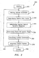
- Figure 2 depicts a generalized flowchart of the process 300 for implementing the present invention
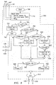
- Figure 3 depicts the block diagram 400 of a control system for implementing the present invention.
- the block diagram of Figure 3 is broken up into sub-processes that are depicted by Figures 5, 6, and 9.
- Figure 5 depicts a block diagram of a yaw rate command interpreter (YRCI) process
- Figure 6 depicts a block diagram of a yaw rate feedback (YRFB) process
- Figure 9 depicts a block diagram of a side-slip rate feedback (SRFB) process.
- YRCI yaw rate command interpreter
- YRFB yaw rate feedback
- SRFB side-slip rate feedback
- Control logic passes to each of the sub-processes as appropriate and then returns to the main process of Figure 3.
- the sub-processes depicted by Figures 6 and 9 have sub-sub-processes as depicted by Figures 7, 8 and 10, 11, respectively.
- Figure 7 depicts a flowchart of a proportional control calculation process used in the process of Figure 6
- Figure 8 depicts a flowchart of a yaw rate feedback entrance/exit criteria process used in the process of Figure 6
- Figure 10 depicts a flowchart of a proportional control calculation process used in the process of Figure 9
- Figure 11 depicts a flowchart of a side-slip rate feedback entrance/exit criteria process used in the process of Figure 9.
- the graphical representation of gain factors depicted in Figure 4 is used in the open-loop control process of Figure 3.
- a generalized flowchart 300 for implementing the present invention begins at start 310, which includes an initialization procedure that resets all of the system flags, registers and timers.
- Control logic then enters control loop 320, which includes the steps of; sensing 330 vehicle parameters from the various sensors discussed above, and more specifically for sensing the vehicle speed, the front wheel steering angle, the vehicle yaw rate, and the vehicle lateral acceleration, determining 340 control gain factors from, for example, look-up tables, determining 345 a desired vehicle dynamic response in response to a vehicle parameter, such as vehicle velocity, for example, determining 350 the state of control flags, for example, the yaw rate and side-slip rate control flags, calculating 360 a control command for rear wheel steering mechanism control system 150, and actuating 370 rear wheel control mechanism 90 in response thereto.
- One pass through control loop 320 is completed for each sampling interval T.
- Process 300 ends 370 when controller 200 interrupts the process or electrical system 70 powers down.
- Process 400 includes an open-loop control process, block 410, a yaw rate command interpreter process, block 420, a yaw rate feedback process, block 430, and a side-slip rate feedback process, block 440.
- Process 400 also depicts vehicle 10 with sensor outputs for yaw rate sensor 110, velocity sensor 120, lateral acceleration sensor 130, and front wheel steering angle sensor 140.
- a rear wheel steering command (RWSC) 450 provides process input to vehicle 10, whereby rear wheel steering mechanism control system 150 actuates rear wheel steering mechanism 90 in response thereto.
- the open-loop control process of block 410 shown in Figure 3 receives inputs from velocity sensor 120 and front wheel steering angle sensor 140, and provides the output open-loop rear wheel steering angle command (ORWSC) 460 as determined by ⁇ r from Equation 1.
- ORWSC open-loop rear wheel steering angle command
- the value for ⁇ f in Equation 1 is provided by front wheel steering angle sensor 140.
- the value for R/F in Equation 1 is obtained from the information contained in the graph depicted in Figure 4, which may be provided by a curve fit equation or a look-up table (not shown).
- a graph 412 depicting R/F 414 as a function of vehicle speed 416 is shown for two conditions; non-trailering 417 and trailering 418.
- Trailer mode selection switch 170 suitably located for access by a driver, provides controller 200 with information regarding the trailering condition.
- controller 200 determines an appropriate R/F from Figure 4, and applies Equation 1 to determine a value ⁇ r for the open-loop rear wheel steering command 460 output.
- t he value of R/F for b oth trailering a nd n on-trailering modes is negative for vehicle speeds less than approximately 3 5-kph and positive for vehicle speeds greater than approximately 65-kph.
- the open-loop rear wheel steering is said to be in-phase with, or steered in the same direction as, the front wheels.
- the open-loop r ear w heel s teering is said to be out-of-phase w ith, or steered in the opposite direction to, the front wheels.
- the vehicle stability can be enhanced at both low and high speeds.
- additional vehicle stability enhancement can be achieved by combining the open-loop rear wheel steering control with yaw rate feedback and side-slip rate feedback controls, as discussed below.
- the yaw rate command interpreter (YRCI) process of block 420 includes a desired yaw rate (YRdes) process, block 470, and a surface identification (SID) process, block 480.
- YRdes desired yaw rate
- SID surface identification
- the YRdes process of block 470 receives inputs from velocity sensor 120, front wheel steering angle sensor 140, open-loop rear wheel steering command 460, and provides the output, desired yaw rate (YRdes) 472, in accordance with Equation 2 and Figure 5.
- r*(s) aCf I z s + V x ⁇ n 2 L+K u V x 2 s 2 +2 ⁇ n s+ ⁇ n 2 ⁇ f (s)- bC r I z s + V x ⁇ n 2 L+K u V x 2 s 2 +2 ⁇ n s+ ⁇ n 2 ⁇ f (s) G R/F .
- Equation 2 calculates a value for r*(s), which is YRdes expressed in the frequency domain.
- Equation 2 is alternatively referred to as a frequency domain form of a high-coefficient y aw-rate reference model, which represents the desired yaw rate under dry road surface conditions, alternatively referred to as high coefficient (high friction coefficient) surface conditions.
- C ontroller 2 00 a pplies t he r espective se nsor inputs and k nown vehicle parameters to Equation 2 and provides process output, YRdes 472.
- SID surface identification
- the SID process of block 480 in Figure 3 receives inputs from lateral acceleration sensor 130, YRdes 472, and yaw rate control flag (CLQS4_YR) 439, which will be discussed below in reference to Figure 8, and provides process output, yaw rate command (YRcmd) 484, in accordance with Equations 3 and 4, and Figure 8.
- yaw rate control flag When yaw rate control flag is (0), then YRcmd is equal to YRdes, per Equation 4. When yaw rate control flag is (1), then YRcmd is equal to YRdes multiplied by a surface identification estimate, ⁇ e, per Equation 3. When used as in Equation 3, surface identification estimation, ⁇ e, acts as a control gain factor. Surface identification estimate, ⁇ e, is determined in accordance with the process described in commonly assigned U.S. Patent No.
- Controller 200 applies the sensor input 130, intermediate control calculation 472 and control flag condition 439, to Equations 3 and 4, and provides process output, YRcmd 484.
- the yaw rate feedback process of block 430 receives inputs from velocity sensor 120, 2WD/4WD mode selection switch 160, and yaw rate integrator 486, and provides the process outputs of rear wheel yaw rate feedback (RW YRFB ) 438 and yaw rate control flag (CLQS4_YR) 439, in accordance with Equations 9 and 10, and Figures 6-8, as discussed below.
- RW YRFB rear wheel yaw rate feedback
- CLQS4_YR yaw rate control flag
- Yaw integrator 486, as shown in Figures 3 and 6, receives inputs from yaw rate sensor 110 and from the process of block 420, which is YRcmd 484, and provides the output of yaw rate error (YRE) 487, in accordance with Equation 5.
- YRE YR-Yrcmd.
- FIG. 6 depicts an expanded version of the yaw rate feedback process of block 430 in Figure 3.
- integrator input signals YRcmd 484 and YR 110 are first filtered by filtering processes 500, 510 sufficient to remove excessive noise.
- the filtered YRE 487 is then used to form a derivative control component for rear wheel steering (RW YRd ) 520 and a proportional control component for rear wheel steering (RW YRp ) 530.
- the filtered yaw rate error YRE 487 is first processed for its time derivative 512, which is followed by a process 514 to calculate the derivative control component by multiplying the filtered time derivative of YRE by a constant gain factor G d , for example 0.01, in accordance with Equation 6, to provide the derivative control component RW YRd 520.
- RW YRd YRE'*Gd.
- the filtered yaw rate error YRE 487 is first additionally filtered 516 to remove any remaining undesirable noise, thereby providing a filtered yaw rate error ⁇ r 518.
- the proportional control component 530 is then calculated according to the process of block 600 and the flowchart of Figure 7.
- Block 600 starts at 610 and then receives inputs 620 from the filtered yaw rate error 518, the 2WD/4WD mode selection switch 160, and vehicle speed sensor 120. Controller 200 then enters, or accesses, look-up T able-1, s hown b elow, to determine 6 30 a p roportional yaw r ate control gain G pYR based on vehicle speed V x . f YR (V x ) Vehicle Speed(kph) V x 0 24 29 34 40 60 80 100 120 Gain G pYR 0 0.326 0.618 0.101 0.07 0.055 0.055 0.03 0
- Controller 200 performs interpolation or extrapolation calculations on the values of Table-1 as necessary to obtain intermediate or out-of-bound values. It will be appreciated in later references to look-up tables, that the interpolation/extrapolation operation performed by controller 200 on Table-1 is also applicable to the analysis involving other look-up table values. Control logic then continues to block 640 where a determination is made regarding the position of the 2WD/4WD mode selection switch 160. If switch 160 is in the 2WD position, then the yaw rate gain mulitiplier G mYR is set 650 to the 2WD multiplier in accordance with the value for G 2WDYR .
- the yaw rate gain multiplier G mYR is set 660 to the 4WD multiplier in accordance with value for G 4WDYR .
- control logic continues to block 670, where the proportional control component RW YRp is calculated in accordance with Equation 7.
- RW YRp ⁇ r * G pYR * G mYR .
- the process of block 600 then exits at block 680 and control logic is sent back to the process of block 430 in Figure 6 from whence it came.
- the outputs of derivative control calculation, block 514, and proportional control calculation, block 600 are RW YRd 520 and RW YRp 530, respectively, which are added together by integrator 535 to provide RW YR 540 in accordance with Equation 8.
- RW YR RW YRd + RW Yrp .
- RW YR 540 is combined with YRE 487 and vehicle velocity V x , from velocity sensor 120, to provide the inputs to the Yaw Rate Feedback Entrance/Exit Criteria 550.
- the process of block 550 follows the logical process depicted in the flowchart in block 550 of Figure 8 and produces the outputs, RW YRFB (rear wheel yaw rate feedback) 438 and CLQS4_YR (yaw rate control flag) 439.
- the process depicted in block 550 of Figure 8 is an expanded version of the process depicted by block 550 of Figure 6.
- the process of block 550 starts at 700 followed by the receiving of input data 710, which includes vehicle speed V x from velocity sensor 120, rear wheel yaw rate feedback RW YR 540, and filtered yaw rate error YRE 487.
- the control logic determines whether the vehicle speed V x is less than a predefined threshold value V th . If the conditions of block 720 are satisfied, control logic passes to block 730, which sets the yaw rate control flag CLQS4_YR to (0) and sets the logic counter Cntr to (0). After block 730, control logic exits the process of block 550 at block 740, and returns to the process of block diagram 430 in Figure 6 from whence it came.
- control logic passes to block 750 where it is determined whether CLQS4_YR is set to (0) or not. If the conditions of block 750 are satisfied, control logic passes to block 760 where it is determined whether the absolute value of yaw rate error
- the first yaw rate deadband threshold DB1 YR is obtained by controller 200 entering look-up Table-2, shown below with the vehicle velocity V x and returning with the gain value DB1 YR .
- control logic passes to block 770, which sets the yaw rate control flag CLQS4_YR to (1) and sets the logic counter Cntr to the predefined value C 0 .
- control logic exits the process of block 550 at block 810, and returns to the process of block diagram 430 in Figure 6 from whence it came. If the conditions at block 760 are not satisfied, control logic passes to block 780 and proceeds as discussed above. If the conditions of block 750 are not satisfied, control logic passes to block 820 where it is determined whether the absolute value of yaw rate error
- control logic passes to block 830 where logic counter Cntr is decremented, and then to block 840 where it is determined whether logic counter Cntr is less than (0). If the conditions of block 840 are satisfied, then block 850 sets the yaw rate control flag CLQS4_YR to (0) and sets the logic counter Cntr to (0). After block 850, control logic passes to block 780 and proceeds as discussed above. When exiting the process of block 550 at block 810, both the yaw rate control flag CLQS4_YR 439 and the rear wheel yaw rate feedback RW YRFB 438 are set.
- the outputs of block 550 in Figures 6 and 8, and block 430 in Figure 6, are rear wheel yaw rate feedback RW YRFB 438 and yaw rate control flag CLQS4_YR 439.
- the logic flow at this point is best seen by now referring back to block 430 of Figure 3, which shows outputs 438, 439.
- Output 439 (yaw rate control flag CLQS4_YR) is one of the inputs to block 440, side-slip rate feedback SRFB.
- Other inputs to block 440 include vehicle yaw rate from sensor 110, vehicle velocity from sensor 120, vehicle lateral acceleration from sensor 130, and 2WD/4WD mode from switch 160.
- the side-slip rate feedback (SRFB) process of block 440 is best seen by now referring to Figure 9.
- Block 440 in Figure 9 shows inputs from sensors 110, 120 and 130, mode switch 160, and control flag 439.
- the side-slip rate V y _ dot 910 is computed at block 900 according to Equation 11, and is used as an input to the proportional control algorithm of block 920.
- V y_dot A y -YR*V x .
- FIG. 10 Other inputs to block 920 include V x from sensor 120 and 2WD/4WD mode selection from switch 160.
- the proportional control algorithm of block 920 is best seen by now referring to Figure 10, where controller 200 starts at block 925, receives inputs at block 930 from 120, 160 and 910, and continues to block 935 where proportional side-slip rate control gain G pSR is determined by controller 200 entering look-up Table-4, shown below, with information relating to vehicle speed V x .
- Controller 200 performs interpolation or extrapolation calculations on the values of Table-4 as necessary.
- the process of block 920 continues to block 940 where it is determined whether 2WD/4WD mode selection switch 160 is set in 2WD mode or not. If the conditions of block 940 are satisfied, control logic passes to block 945 where a side-slip rate gain multiplier G mSR is set equal to the side-slip rate gain multiplier G 2WDSR for 2WD driving mode status. If the conditions of block 940 are not satisfied, control logic passes to block 950 where a side-slip rate gain multiplier G mSR is set equal to the side-slip rate gain multiplier G 4WDSR for 4WD driving mode status. After blocks 945 and 950, control logic passes to block 955 where rear wheel side-slip rate component RW SR is calculated in accordance with Equation 12.
- RW SR V y_dot * G pSR * G mSR .
- control logic exits, block 960, the process of block 920 and returns to the process of block 440 in Figure 9 from whence it came.
- the output of block 920 is rear wheel side-slip rate component RW SR 965, as shown in Figures 9 and 10.
- side-slip rate feedback entrance/exit criteria process depicted by block 970, has the inputs rear wheel side-slip rate component RW SR 965, vehicle speed from sensor 120, side-slip rate V y_dot 910, and yaw rate control flag CLQS4_YR 439.
- controller 200 starts the process at block 980, receives the noted inputs at block 985, and then proceeds to block 990 where the control logic determines whether the vehicle velocity V x is less than a predefined velocity threshold V th .
- control logic passes to block 995 where the side-slip rate control flag CLQS4_SR is set to (0) and the logic counter C ntr is set to (0).
- control logic exits the process of block 970 at block 1000 and returns to the process of block 440 in Figure 9 from whence it came.
- the value of rear wheel side-slip rate feedback RW SRFB 1700 remains unchanged. If the conditions of block 990 are not satisfied, control logic passes to block 1050 where it is determined whether side-slip rate control flag CLQS4_SR is set to (0) or not.
- control logic passes to block 1100 where it is determined whether the absolute value of V y_dot is greater than a first side-slip rate deadband threshold DB1 SR .
- the first side-slip rate deadband threshold DB1 SR is obtained by controller 200 entering look-up Table-5, shown below, with the vehicle velocity V x and returning with the gain value DB1 SR .
- control logic passes to block 1350 where CLQS4_SR is set to (0) and control counter Cntr is set to (0).
- control logic passes to block 1400 and proceeds as discussed above. After blocks 1300 and 1400, control logic exits the process of block 970 at block 1450. If the conditions of block 1050 are not satisfied, control logic passes to block 1500 where it is determined whether the absolute value of V y_dot is less than a second side-slip rate deadband threshold DB2 SR .
- the second side-slip rate deadband threshold DB2 SR is obtained by controller 200 entering look-up Table-6, shown below, with the vehicle velocity V x and returning with the gain value DB2 SR .
- control logic passes to block 1550 where control counter Cntr is decremented, and then to block 1600 where it is determined whether control counter Cntr is less that (0). If the conditions of block 1600 are satisfied, control logic passes to block 1650 where CLQS4_SR is set to (0) and control counter Cntr is set to (0). After block 1650, control logic passes to block 1200 and proceeds as discussed above. If the conditions of block 1600 are not satisfied, control logic passes to block 1200 and proceeds as discussed above.
- integrator 1750 receives the inputs rear wheel yaw rate feedback (RW YRFB ) 438, open-loop rear wheel steering angle command (ORWSC) 460, and rear wheel side-slip rate feedback (RW SRFB ) 1700, and provides the output rear wheel steering command (RWSC) 450 in accordance with Equation 15.
- RWSC ORWSC + RW YRFB + RW SRFB (see Fig. 3).
- the rear wheel steering command (RWSC) 450 is used by controller 200 for controlling rear wheel steering mechanism control system 150 as it adjusts rear wheel steering mechanism 90 in accordance with the control logic herein described.
- Figure 12 depicts the response of a first vehicle undergoing the aforementioned maneuver where the first vehicle has rear wheel steering controlled only by an open-loop rear wheel steering angle command.
- the peak SWD 1800 is approximately 420-degrees
- the peak SSA 1850 is approximately 20-degrees.
- Figure 13 depicts the response of a second vehicle undergoing the same maneuver where the second vehicle has rear wheel steering controlled in accordance with the present invention, as depicted in Figures 2-11.
- the peak SWD 2000 is approximately 315-degrees
- the peak SSA 2050 is approximately 13-degrees, a reduction of 25% and 35%, respectively, as compared to the response of the first vehicle.
- vehicle directional stability during maneuvering can be achieved without differential braking, thereby enabling a vehicle stability enhancement (VSE) system to provide a corrective yaw moment to a vehicle without a reduction in vehicle speed, which would result from a controlled differential braking condition.
- VSE vehicle stability enhancement
Abstract
Description
- This invention relates generally to a vehicle, and more particularly to a method and apparatus for stabilizing the vehicle using a vehicle stability enhancement (VSE) system.
- Traditional vehicle chassis subsystems, such as steering, braking and suspension subsystems, are passive, meaning that their responsiveness under operating conditions is determined prior to the vehicle leaving the point of manufacture. Advances in braking system technology have led to differential braking using vehicle yaw-rate feedback. Such advances have been incorporated into vehicle stability enhancement systems, whereby an onboard controller monitors the vehicle yaw rate, determines an appropriate control command to improve vehicle directional stability, and effectuates actuation of appropriate braking mechanisms to create a corrective yaw moment. Such vehicle stability enhancement systems typically result in a reduction of vehicle speed due to the action of the braking mechanisms.
- In one embodiment, a vehicle stability enhancement system for a vehicle having at least one vehicle subsystem includes at least one sensor for sensing at least one vehicle parameter, at least one vehicle control system for adjusting the at least one vehicle subsystem wherein the at least one vehicle control system includes a rear wheel steering control system, at least one memory including at least one set of gain factors, and a controller responsive to the at least one sensor and the at least one set of gain factors for controlling the at least one vehicle control system.
- In another embodiment, a method for controlling a vehicle stability enhancement system in a vehicle having at least one vehicle subsystem includes sensing at least one vehicle parameter, determining at least one control gain factor in response to the at least one vehicle parameter, determining the state of at least one control flag in response to the at least one vehicle parameter, calculating at least one control command in response to the at least one control gain factor and the at least one control flag, and actuating at least one vehicle control system in response to the at least one control command for adjusting the at least one vehicle subsystem.
- Referring now to the figures, which are exemplary embodiments, and wherein like elements are numbered alike:
- Fig. 1 depicts a generalized schematic of a vehicle operative for implementing the present invention;
- Fig. 2 depicts a generalized flowchart of a process for implementing the present invention;
- Fig. 3 depicts a block diagram of a control system for implementing the present invention;
- Fig. 4 depicts a graphical representation of gain factors for implementing the present invention;
- Fig. 5 depicts a block diagram of a yaw rate command interpreter (YRCI) process for use in the control system of Fig. 3;
- Fig. 6 depicts a block diagram of a yaw rate feedback (YRFB) process for use in the control system of Fig. 3;
- Fig. 7 depicts a flowchart of a proportional control calculation process for use in the process of Fig. 6;
- Fig. 8 depicts a flowchart of a yaw rate feedback entrance/exit criteria process for use in the process of Fig. 6;
- Fig. 9 depicts a block diagram of a side-slip rate feedback (SRFB) process for use in the control system of Fig. 3;
- Fig. 10 depicts a flowchart of a proportional control calculation process for use in the process of Fig. 9;
- Fig. 11 depicts a flowchart of a side-slip rate feedback entrance/exit criteria process for use in the process of Fig. 9;
- Fig. 12 depicts a graphical representation of a vehicle performance responsive to a feedforward rear wheel steering control; and
- Fig. 13 depicts a graphical representation of a vehicle performance responsive to rear wheel steering control in accordance with the present invention.
- A detailed description of an embodiment of the present invention is presented herein by way of exemplification and not limitation with reference to Figures 1-13.
- Figure 1 depicts a generalized schematic of a
vehicle 10 having achassis 20, abody 30 arranged onchassis 20, a set ofwheels 40 rotationally coupled tochassis 20, a frontwheel steering mechanism 50 arranged for steeringfront wheels 42, asteering wheel 60 for transferring a driver c ommanded steering torque to thesteering mechanism 50, a rearwheel steering mechanism 90 arranged for steeringrear wheels 44, and acontrol system 100. The front ofvehicle 10 is depicted byarrow 80. Rearwheel steering mechanism 90 may be of the kind found in the rear wheel steer system of General Motors (GM) Sierra Denali pickup truck, Model-Year 2002.Steering mechanisms control system 100 includes the following sensors: a y aw rate sensor (YR) 110 for sensing the actual vehicle yaw rate; velocity sensor (VS) 120 for sensing the velocity ofvehicle 10; a lateral acceleration sensor (Ay) 130, such as for example an accelerometer, for sensing the value of the vehicle's lateral acceleration; and a front wheel steering angle sensor (FWSS) 140 for sensing the angle of steer offront steering mechanism 50. The sensed parameters are alternatively referred to as vehicle parameters. Thecontrol system 100 also includes a rear wheel steeringmechanism control system 150, alternatively referred to as a vehicle control system, which may include, for example, electronically controlled a ctuators and dampers, for adjusting the rearwheel steering mechanism 90. Thecontrol system 100 further includes: a two-wheel drive/four-wheel drive (2WD/4WD)mode selection switch 160 for selecting a two-wheel drive, where the vehicle is driven by wheels on one axle only regardless of the existence of a physical linkage between the driving wheels, or four-wheel drive driving mode where the vehicle is driven by wheels on more than one axle, a trailermode selection switch 170 for selecting a driving mode that accounts for the presence or absence of a towed trailer; and acentral controller 200 arranged in operable communication withsensors vehicle control system 150.Control lines controller 200 and/or actuating thevehicle control system 150. - 2WD/4WD
mode selection switch 160 and trailermode selection switch 170 may be a pushbutton type switch or a toggle type switch, or any other type of switch suitable for producing an appropriate mode selection signal.Switches Controller 200 includes amemory 210 for storing sensor information, register information, flag settings, look-up tables of gain factors, and any other relevant information, as discussed below. The vehicleelectrical system 70 provides electrical power to all of the vehicle's electrically operated systems, including thecontroller 200 and thevehicle control system 150. - It will be appreciated that while the disclosed embodiment refers to a vehicle, such as an automobile, having four wheels, the invention described herein is applicable to any vehicle with any number of wheels that may be arranged to employ rear wheel steering.
- The nomenclature used herein for implementing the present invention includes the following variables:
-
- Cf = front cornering stiffness;
- Cr = rear cornering stiffness;
- a = distance from front axle to center of gravity;
- b = distance from rear axle to center of gravity;
- L = vehicle wheel base;
- Iz = vehicle yaw inertia;
- Ku = vehicle understeer coefficient (typically 6 deg/g lateral acceleration);
- Vx = vehicle speed (kilometers-per-hour, kph);
- Vth = vehicle speed threshold (kilometers-per-hour, kph), for example, 10-kph;
- ωn = desired vehicle natural frequency;
- ζ = desired vehicle damping ratio (typically about 0.7);
- δf = front wheel steering angle;
- δr = open-loop rear wheel steering angle;
- ORWSC = open-loop rear wheel steering angle command;
- R/F = ratio of rear steering angle to front steering angle;
- GR/F = gain from ratio of rear steering angle to front steering angle;
- YR = vehicle actual yaw rate, (degrees-per-second, deg/sec));
- Ay = vehicle lateral acceleration (g-force);
- Gd = yaw rate error gain (a constant, for example 0.01, or a function of vehicle speed);
- GpYR = proportional yaw rate control gain;
- G2WDYR = yaw rate gain multiplier for 2WD status, for example, 0.55;
- G4WDYR = yaw rate gain multiplier for 4WD status, for example, 1.00;
- GmYR = yaw rate gain multiplier depending on 2WD/4WD status;
- GpSR = proportional side-slip rate control gain;
- G2WDSR = side-slip rate gain multiplier for 2WD status, for example, 0.78;
- G4WDSR = side-slip rate gain multiplier for 4WD status, for example, 1.00;
- GmSR = side-slip rate gain multiplier depending on 2WD/4WD status;
- T = control sampling time interval, for example, 10-milliseconds (msec);
- Cntr = logic counter (a count of one equates to a time period of T);
- C0 = predefined value for logic counter, for example, 500 (500*T=5 seconds);
- DB1YR = first deadband threshold for yaw rate;
- DB2YR = second deadband threshold yaw rate;
- DB1SR = first deadband threshold for side-slip rate;
- DB2SR = second deadband threshold side-slip rate.
-
-
- YRFB = yaw rate feedback;
- SRFB = side-slip rate feedback;
- µe = surface identification estimate;
- CLQS4_YR = yaw rate control flag;
- YRdes = yaw rate desired;
- YRcmd = yaw rate command;
- SID = surface identification;
- YRE = yaw rate error;
- r*(s) = YRdes expressed in the frequency domain;
- RWYRd = rear wheel yaw rate derivative component;
- RWYRp = rear wheel yaw rate proportional component;
- RWYR = rear wheel yaw rate feedback control;
- Δr = filtered yaw rate error;
- RWYRFB = rear wheel yaw rate feedback;
- Vy_dot = vehicle side-slip rate;
- RWSR = rear wheel side-slip rate component;
- RWSRFB = rear wheel side-slip rate feedback;
- CLQS4_SR = side-slip rate control flag (indicates state of vehicle lateral acceleration relative to a threshold value);
- RWSC = rear wheel steering command.
-
- Quotations (" ") surrounding a variable name represents a register in
memory 210 containing the value of the respective variable, "| |" designates an "absolute value" operator, and a single quotation (') following a variable name designates a "derivative" operator. A variable name presented in an equation represents a value associated with the respective variable, and a variable name presented in a process represents a command having a command signal associated with a related value stored in a register inmemory 210. Accordingly, a process output results in a command having a command signal. - Controller 2 00 is a m icroprocessor b ased c ontrol sy stem a dapted for controlling vehicle subsytems, and more particularly, for controlling the rear
wheel steering mechanism 90 in accordance with control logic described herein.Controller 200 typically includes a microprocessor, amemory 210, such as, for example, ROM and RAM, and appropriate input and output circuits of a known type for receiving the various input signals and for outputting the various control commands to the various actuators and control systems. The control logic implemented bycontroller 200 is cycled at a control sampling rate of T, and is best seen by referring to Figures 2-11. - In general, Figures 2-11 depict a series of flowcharts and block diagrams that represent the logic that is implemented by
controller 200. Figure 2 depicts a generalized flowchart of theprocess 300 for implementing the present invention, while Figure 3 depicts the block diagram 400 of a control system for implementing the present invention. The block diagram of Figure 3 is broken up into sub-processes that are depicted by Figures 5, 6, and 9. Figure 5 depicts a block diagram of a yaw rate command interpreter (YRCI) process, Figure 6 depicts a block diagram of a yaw rate feedback (YRFB) process, and Figure 9 depicts a block diagram of a side-slip rate feedback (SRFB) process. Control logic passes to each of the sub-processes as appropriate and then returns to the main process of Figure 3. The sub-processes depicted by Figures 6 and 9 have sub-sub-processes as depicted by Figures 7, 8 and 10, 11, respectively. Figure 7 depicts a flowchart of a proportional control calculation process used in the process of Figure 6, Figure 8 depicts a flowchart of a yaw rate feedback entrance/exit criteria process used in the process of Figure 6, Figure 10 depicts a flowchart of a proportional control calculation process used in the process of Figure 9, and Figure 11 depicts a flowchart of a side-slip rate feedback entrance/exit criteria process used in the process of Figure 9. The graphical representation of gain factors depicted in Figure 4 is used in the open-loop control process of Figure 3. - Referring to Figure 2, a
generalized flowchart 300 for implementing the present invention begins atstart 310, which includes an initialization procedure that resets all of the system flags, registers and timers. Control logic then enterscontrol loop 320, which includes the steps of; sensing 330 vehicle parameters from the various sensors discussed above, and more specifically for sensing the vehicle speed, the front wheel steering angle, the vehicle yaw rate, and the vehicle lateral acceleration, determining 340 control gain factors from, for example, look-up tables, determining 345 a desired vehicle dynamic response in response to a vehicle parameter, such as vehicle velocity, for example, determining 350 the state of control flags, for example, the yaw rate and side-slip rate control flags, calculating 360 a control command for rear wheel steeringmechanism control system 150, and actuating 370 rearwheel control mechanism 90 in response thereto. One pass throughcontrol loop 320 is completed for each samplinginterval T. Process 300 ends 370 whencontroller 200 interrupts the process orelectrical system 70 powers down. - Referring now to Figure 3, a
process 400, in block diagram representation, is presented, which represents thecontrol loop 320 process of Figure 2.Process 400 includes an open-loop control process, block 410, a yaw rate command interpreter process, block 420, a yaw rate feedback process, block 430, and a side-slip rate feedback process, block 440.Process 400 also depictsvehicle 10 with sensor outputs foryaw rate sensor 110,velocity sensor 120,lateral acceleration sensor 130, and front wheelsteering angle sensor 140. A rear wheel steering command (RWSC) 450 provides process input tovehicle 10, whereby rear wheel steeringmechanism control system 150 actuates rearwheel steering mechanism 90 in response thereto. - The open-loop control process of
block 410 shown in Figure 3 receives inputs fromvelocity sensor 120 and front wheelsteering angle sensor 140, and provides the output open-loop rear wheel steering angle command (ORWSC) 460 as determined by δr fromEquation 1. - The value for δf in
Equation 1 is provided by front wheelsteering angle sensor 140. The value for R/F inEquation 1 is obtained from the information contained in the graph depicted in Figure 4, which may be provided by a curve fit equation or a look-up table (not shown). Referring now to Figure 4, agraph 412 depicting R/F 414 as a function ofvehicle speed 416 is shown for two conditions; non-trailering 417 and trailering 418. Trailermode selection switch 170, suitably located for access by a driver, providescontroller 200 with information regarding the trailering condition. Provided with a traileringmode 417, 418 fromswitch 170, thevehicle speed 416 fromsensor 120, and the front wheel steering angle δf fromsensor 140,controller 200 determines an appropriate R/F from Figure 4, and appliesEquation 1 to determine a value δr for the open-loop rearwheel steering command 460 output. - As s hown in Figure 4, t he value of R/F for b oth trailering a nd n on-trailering modes is negative for vehicle speeds less than approximately 3 5-kph and positive for vehicle speeds greater than approximately 65-kph. Where the R/F ratio is positive, the open-loop rear wheel steering is said to be in-phase with, or steered in the same direction as, the front wheels. Where the R/F ratio is negative, the open-loop r ear w heel s teering is said to be out-of-phase w ith, or steered in the opposite direction to, the front wheels. With such open-loop rear wheel steering, the vehicle stability can be enhanced at both low and high speeds. However, additional vehicle stability enhancement can be achieved by combining the open-loop rear wheel steering control with yaw rate feedback and side-slip rate feedback controls, as discussed below.
- The yaw rate command interpreter (YRCI) process of
block 420, shown in Figures 3 and 5, includes a desired yaw rate (YRdes) process, block 470, and a surface identification (SID) process, block 480. - Referring now to Figure 5, the YRdes process of
block 470 receives inputs fromvelocity sensor 120, front wheelsteering angle sensor 140, open-loop rearwheel steering command 460, and provides the output, desired yaw rate (YRdes) 472, in accordance with Equation 2 and Figure 5. - As discussed above and depicted in Figure 5, Equation 2 calculates a value for r*(s), which is YRdes expressed in the frequency domain. Equation 2 is alternatively referred to as a frequency domain form of a high-coefficient y aw-rate reference model, which represents the desired yaw rate under dry road surface conditions, alternatively referred to as high coefficient (high friction coefficient) surface conditions. C ontroller 2 00 a pplies t he r espective se nsor inputs and k nown vehicle parameters to Equation 2 and provides process output,
YRdes 472. To account for low coefficient road surface conditions, such as when the road is wet or icy, the desired yaw rate needs to be modified using a surface identification (SID) process. - The SID process of
block 480 in Figure 3 receives inputs fromlateral acceleration sensor 130,YRdes 472, and yaw rate control flag (CLQS4_YR) 439, which will be discussed below in reference to Figure 8, and provides process output, yaw rate command (YRcmd) 484, in accordance withEquations 3 and 4, and Figure 8. - When yaw rate control flag is (0), then YRcmd is equal to YRdes, per
Equation 4. When yaw rate control flag is (1), then YRcmd is equal to YRdes multiplied by a surface identification estimate, µe, per Equation 3. When used as in Equation 3, surface identification estimation, µe, acts as a control gain factor. Surface identification estimate, µe, is determined in accordance with the process described in commonly assigned U.S. Patent No. 6,125,319 entitled "Brake System Control Method Responsive to Measured Vehicle Acceleration", filed August 17, 1998 (the '319 patent), and more particularly depicted in Figure 4 and described at column 8 throughcolumn 10 of the '319 patent, which is herein incorporated by reference in its entirety, and is generally described as a process for estimating the road surface adhesion characteristic.Controller 200 applies thesensor input 130,intermediate control calculation 472 and controlflag condition 439, toEquations 3 and 4, and provides process output,YRcmd 484. - The yaw rate feedback process of
block 430, shown in Figures 3 and 6, receives inputs fromvelocity sensor 120, 2WD/4WDmode selection switch 160, andyaw rate integrator 486, and provides the process outputs of rear wheel yaw rate feedback (RWYRFB) 438 and yaw rate control flag (CLQS4_YR) 439, in accordance withEquations 9 and 10, and Figures 6-8, as discussed below. -
Yaw integrator 486, as shown in Figures 3 and 6, receives inputs fromyaw rate sensor 110 and from the process ofblock 420, which isYRcmd 484, and provides the output of yaw rate error (YRE) 487, in accordance with Equation 5. - Figure 6 depicts an expanded version of the yaw rate feedback process of
block 430 in Figure 3. Referring now to Figure 6, integrator input signalsYRcmd 484 andYR 110 are first filtered byfiltering processes YRE 487 is then used to form a derivative control component for rear wheel steering (RWYRd) 520 and a proportional control component for rear wheel steering (RWYRp) 530. Regarding the derivative control component, the filtered yawrate error YRE 487 is first processed for itstime derivative 512, which is followed by aprocess 514 to calculate the derivative control component by multiplying the filtered time derivative of YRE by a constant gain factor Gd, for example 0.01, in accordance with Equation 6, to provide the derivativecontrol component RW YRd 520. - Regarding the proportional control component, the filtered yaw
rate error YRE 487 is first additionally filtered 516 to remove any remaining undesirable noise, thereby providing a filtered yawrate error Δr 518. Theproportional control component 530 is then calculated according to the process ofblock 600 and the flowchart of Figure 7. - Referring now to Figure 7, the process of
block 600 starts at 610 and then receivesinputs 620 from the filteredyaw rate error 518, the 2WD/4WDmode selection switch 160, andvehicle speed sensor 120.Controller 200 then enters, or accesses, look-up T able-1, s hown b elow, to determine 6 30 a p roportional yaw r ate control gain GpYR based on vehicle speed Vx.fYR(Vx) Vehicle Speed(kph) V x0 24 29 34 40 60 80 100 120 Gain G pYR0 0.326 0.618 0.101 0.07 0.055 0.055 0.03 0 -
Controller 200 performs interpolation or extrapolation calculations on the values of Table-1 as necessary to obtain intermediate or out-of-bound values. It will be appreciated in later references to look-up tables, that the interpolation/extrapolation operation performed bycontroller 200 on Table-1 is also applicable to the analysis involving other look-up table values. Control logic then continues to block 640 where a determination is made regarding the position of the 2WD/4WDmode selection switch 160. Ifswitch 160 is in the 2WD position, then the yaw rate gain mulitiplier GmYR is set 650 to the 2WD multiplier in accordance with the value for G2WDYR. Ifswitch 160 is in the 4WD position, then the yaw rate gain multiplier GmYR is set 660 to the 4WD multiplier in accordance with value for G4WDYR. After selecting either the 2WD or 4WD gain, control logic continues to block 670, where the proportional control component RWYRp is calculated in accordance with Equation 7.block 600 then exits atblock 680 and control logic is sent back to the process ofblock 430 in Figure 6 from whence it came. - Referring now to Figure 6, the outputs of derivative control calculation, block 514, and proportional control calculation, block 600, are
RW YRd 520 andRW YRp 530, respectively, which are added together byintegrator 535 to provideRW YR 540 in accordance with Equation 8. -
RW YR 540 is combined withYRE 487 and vehicle velocity Vx, fromvelocity sensor 120, to provide the inputs to the Yaw Rate Feedback Entrance/Exit Criteria 550. The process ofblock 550 follows the logical process depicted in the flowchart inblock 550 of Figure 8 and produces the outputs, RWYRFB (rear wheel yaw rate feedback) 438 and CLQS4_YR (yaw rate control flag) 439. The process depicted inblock 550 of Figure 8 is an expanded version of the process depicted byblock 550 of Figure 6. - Referring now to Figure 8, the process of
block 550 starts at 700 followed by the receiving ofinput data 710, which includes vehicle speed Vx fromvelocity sensor 120, rear wheel yawrate feedback RW YR 540, and filtered yawrate error YRE 487. Atblock 720, the control logic determines whether the vehicle speed Vx is less than a predefined threshold value Vth. If the conditions ofblock 720 are satisfied, control logic passes to block 730, which sets the yaw rate control flag CLQS4_YR to (0) and sets the logic counter Cntr to (0). Afterblock 730, control logic exits the process ofblock 550 atblock 740, and returns to the process of block diagram 430 in Figure 6 from whence it came. When exiting the process ofblock 550 atblock 740, the yaw ratecontrol flag CLQS4_YR 439 is set and the rear wheel yawrate feedback RW YRFB 438 is left unchanged. If atblock 720, the conditions are not satisfied, control logic passes to block 750 where it is determined whether CLQS4_YR is set to (0) or not. If the conditions ofblock 750 are satisfied, control logic passes to block 760 where it is determined whether the absolute value of yaw rate error |YRE| is greater than a first yaw rate deadband threshold DB1YR. The first yaw rate deadband threshold DB1YR is obtained bycontroller 200 entering look-up Table-2, shown below with the vehicle velocity Vx and returning with the gain value DB1YR.DB1YR Vehicle Speed (kph) V x0 10 25 30 60 80 100 Gain DB1YR 15 12 9 8 7 8 9 - If the conditions of
block 760 are satisfied, control logic passes to block 770, which sets the yaw rate control flag CLQS4_YR to (1) and sets the logic counter Cntr to the predefined value C0. Afterblock 770, control logic passes to block 780 where it is determined whether CLQS4_YR is set to (1) or not. If the conditions ofblock 780 are satisfied, control logic passes to block 790 where RWYRFB is set equal to RWYR in accordance with Equation 9.block 780 are not satisfied, control logic passes to block 800 where RWYRFB is set equal to (0) in accordance withEquation 10. - After
blocks block 550 atblock 810, and returns to the process of block diagram 430 in Figure 6 from whence it came. If the conditions atblock 760 are not satisfied, control logic passes to block 780 and proceeds as discussed above. If the conditions ofblock 750 are not satisfied, control logic passes to block 820 where it is determined whether the absolute value of yaw rate error |YRE| is less than a second yaw rate deadband threshold D B2YR. T he second yaw rate d eadband threshold D B2YR i obtained b ycontroller 200 entering look-up Table-3, shown below, with the vehicle velocity Vx and returning with the gain value DB2YR.DB2YR Vehicle Speed (kph) V x0 30 60 80 100 Gain DB2YR 11 5 3 4 5 - If the conditions of
block 820 are satisfied, control logic passes to block 830 where logic counter Cntr is decremented, and then to block 840 where it is determined whether logic counter Cntr is less than (0). If the conditions ofblock 840 are satisfied, then block 850 sets the yaw rate control flag CLQS4_YR to (0) and sets the logic counter Cntr to (0). Afterblock 850, control logic passes to block 780 and proceeds as discussed above. When exiting the process ofblock 550 atblock 810, both the yaw ratecontrol flag CLQS4_YR 439 and the rear wheel yawrate feedback RW YRFB 438 are set. The outputs ofblock 550 in Figures 6 and 8, and block 430 in Figure 6, are rear wheel yawrate feedback RW YRFB 438 and yaw ratecontrol flag CLQS4_YR 439. The logic flow at this point is best seen by now referring back to block 430 of Figure 3, which showsoutputs sensor 110, vehicle velocity fromsensor 120, vehicle lateral acceleration fromsensor 130, and 2WD/4WD mode fromswitch 160. The side-slip rate feedback (SRFB) process ofblock 440 is best seen by now referring to Figure 9. -
Block 440 in Figure 9 shows inputs fromsensors mode switch 160, and controlflag 439. The side-slip rate Vy_dot 910 is computed atblock 900 according to Equation 11, and is used as an input to the proportional control algorithm ofblock 920. - Other inputs to block 920 include Vx from
sensor 120 and 2WD/4WD mode selection fromswitch 160. The proportional control algorithm ofblock 920 is best seen by now referring to Figure 10, wherecontroller 200 starts atblock 925, receives inputs atblock 930 from 120, 160 and 910, and continues to block 935 where proportional side-slip rate control gain GpSR is determined bycontroller 200 entering look-up Table-4, shown below, with information relating to vehicle speed Vx.fSR(Vx) Vehicle Speed (kph) V x0 19 43 62 82 96 120 Gain G pSR0 0.28 0.46 0.87 1.05 1.07 1.1 -
Controller 200 performs interpolation or extrapolation calculations on the values of Table-4 as necessary. The process ofblock 920 continues to block 940 where it is determined whether 2WD/4WDmode selection switch 160 is set in 2WD mode or not. If the conditions ofblock 940 are satisfied, control logic passes to block 945 where a side-slip rate gain multiplier GmSR is set equal to the side-slip rate gain multiplier G2WDSR for 2WD driving mode status. If the conditions ofblock 940 are not satisfied, control logic passes to block 950 where a side-slip rate gain multiplier GmSR is set equal to the side-slip rate gain multiplier G4WDSR for 4WD driving mode status. Afterblocks - After
block 955, control logic exits, block 960, the process ofblock 920 and returns to the process ofblock 440 in Figure 9 from whence it came. The output ofblock 920 is rear wheel side-sliprate component RW SR 965, as shown in Figures 9 and 10. - Referring to Figures 9 and 11, side-slip rate feedback entrance/exit criteria process, depicted by
block 970, has the inputs rear wheel side-sliprate component RW SR 965, vehicle speed fromsensor 120, side-slip rate V y_dot 910, and yaw ratecontrol flag CLQS4_YR 439. Referring now to Figure 11,controller 200 starts the process atblock 980, receives the noted inputs atblock 985, and then proceeds to block 990 where the control logic determines whether the vehicle velocity Vx is less than a predefined velocity threshold Vth. If the conditions ofblock 990 are satisfied, control logic passes to block 995 where the side-slip rate control flag CLQS4_SR is set to (0) and the logic counter C ntr is set to (0). Afterblock 995, control logic exits the process ofblock 970 atblock 1000 and returns to the process ofblock 440 in Figure 9 from whence it came. When exiting the process ofblock 970 atblock 1000, the value of rear wheel side-sliprate feedback RW SRFB 1700 remains unchanged. If the conditions ofblock 990 are not satisfied, control logic passes to block 1050 where it is determined whether side-slip rate control flag CLQS4_SR is set to (0) or not. If the conditions ofblock 1050 are satisfied, control logic passes to block 1100 where it is determined whether the absolute value of Vy_dot is greater than a first side-slip rate deadband threshold DB1SR. The first side-slip rate deadband threshold DB1SR is obtained bycontroller 200 entering look-up Table-5, shown below, with the vehicle velocity Vx and returning with the gain value DB1SR.DB1SR Vehicle Speed (kph) V x0 10 25 30 48 56 80 100 Gain DB1 SR0 1 2 3 5 4 2.9 4 - If the conditions of
block 1100 are satisfied, control logic passes to block 1150 where CLQS4_SR is set to (1) and control counter Cntr is set to the predefined value C0. Afterblock 1150, control logic passes to block 1200. If the conditions ofblock 1100 are not satisfied, control logic passes to block 1200. Atblock 1200,controller 200 determines whether CLQS4_SR is set to (1) or not. If the conditions ofblock 1200 are satisfied, control logic passes to block 1250 where it is determined whether CLQS4_YR is set to (1) or not. If the conditions ofblock 1250 are satisfied, control logic passes to block 1300 where RWSRFB is set equal to RWSR in accordance with Equation 13. - If the conditions of
block 1250 are not satisfied, control logic passes to block 1350 where CLQS4_SR is set to (0) and control counter Cntr is set to (0). Afterblock 1350, control logic passes to block 1400 where RWSRFB is set equal to (0) in accordance with Equation 14. - If the conditions of
block 1200 are not satisfied, control logic passes to block 1400 and proceeds as discussed above. Afterblocks block 970 atblock 1450. If the conditions ofblock 1050 are not satisfied, control logic passes to block 1500 where it is determined whether the absolute value of Vy_dot is less than a second side-slip rate deadband threshold DB2SR. The second side-slip rate deadband threshold DB2SR is obtained bycontroller 200 entering look-up Table-6, shown below, with the vehicle velocity Vx and returning with the gain value DB2SR.DB2SR Vehicle Speed (kph) V x0 10 25 30 48 60 80 100 Gain DB2sR 0 0.7 1.2 1.7 3 2.2 1.5 2.2 - If the conditions of
block 1500 are satisfied, control logic passes to block 1550 where control counter Cntr is decremented, and then to block 1600 where it is determined whether control counter Cntr is less that (0). If the conditions ofblock 1600 are satisfied, control logic passes to block 1650 where CLQS4_SR is set to (0) and control counter Cntr is set to (0). Afterblock 1650, control logic passes to block 1200 and proceeds as discussed above. If the conditions ofblock 1600 are not satisfied, control logic passes to block 1200 and proceeds as discussed above. When the process ofblock 970 exits atblock 1450, the value of rear wheel side-sliprate feedback RW SRFB 1700 is set to either (0) or RWSR and the control logic passes back to the process ofblock 440 in Figure 9 from whence it came. Referring now to Figure 9, the process ofblock 440 concludes with theoutput RW SRFB 1700, as shown in Figures 9 and 3. - Referring now back to Figure 3,
integrator 1750 receives the inputs rear wheel yaw rate feedback (RWYRFB) 438, open-loop rear wheel steering angle command (ORWSC) 460, and rear wheel side-slip rate feedback (RWSRFB) 1700, and provides the output rear wheel steering command (RWSC) 450 in accordance with Equation 15. - The rear wheel steering command (RWSC) 450 is used by
controller 200 for controlling rear wheel steeringmechanism control system 150 as it adjusts rearwheel steering mechanism 90 in accordance with the control logic herein described. - Employing the open-loop rear wheel steering angle command (ORWSC) in combination with the rear wheel yaw rate feedback (RWYRFB) and rear wheel side-slip rate feedback (RWSRFB) in accordance with this invention, a reduction in steering wheel displacement (SWD) and a reduction in vehicle side-slip angle (SSA) during vehicle maneuvering, such as in a double-lane change maneuver on snow at 40 miles per hour, can be achieved, as illustrated by Figures 12 and 13, which depict graphs of steering wheel displacement (SWD), expressed in degrees, and side-slip angle (SSA), expressed in degrees, as a function of time.
- Figure 12 depicts the response of a first vehicle undergoing the aforementioned maneuver where the first vehicle has rear wheel steering controlled only by an open-loop rear wheel steering angle command. As can be seen in Figure 12, the
peak SWD 1800 is approximately 420-degrees, and thepeak SSA 1850 is approximately 20-degrees. - In comparison, Figure 13 depicts the response of a second vehicle undergoing the same maneuver where the second vehicle has rear wheel steering controlled in accordance with the present invention, as depicted in Figures 2-11. As can be seen in Figure 13, the
peak SWD 2000 is approximately 315-degrees, and thepeak SSA 2050 is approximately 13-degrees, a reduction of 25% and 35%, respectively, as compared to the response of the first vehicle. - In accordance with the present invention, vehicle directional stability during maneuvering can be achieved without differential braking, thereby enabling a vehicle stability enhancement (VSE) system to provide a corrective yaw moment to a vehicle without a reduction in vehicle speed, which would result from a controlled differential braking condition.
- While the invention has been described with reference to an exemplary embodiment, it will be understood by those skilled in the art that various changes may be made and equivalents may be substituted for elements thereof without departing from the scope of the invention. I n addition, many modifications may b e made to adapt a particular situation or material to the teachings of the invention without departing from the essential scope thereof. Therefore, it is intended that the invention not be limited to the particular embodiment disclosed as the best mode contemplated for carrying out this invention, but that the invention will include all embodiments falling within the scope of the appended claims.
Claims (27)
- A vehicle s tability enhancement sy stem for a vehicle h aving a 11 east one vehicle subsystem, comprising:at least one sensor for sensing at least one vehicle parameter;at least one vehicle control system for adjusting the at least one vehicle subsystem, said at least one vehicle control system comprising a rear wheel steering control system;at least one memory comprising at least one set of gain factors; anda controller responsive to said at least one sensor and said at least one set of gain factors for controlling said at least one vehicle control system.
- The vehicle stability enhancement system of Claim 1, wherein said rear wheel steering control system is responsive to a rear wheel steering angle command from said controller.
- The vehicle stability enhancement system of Claim 2, wherein said rear wheel steering angle command is responsive to at least two of an open-loop rear wheel steering angle control command, a yaw rate feedback command and a side-slip rate feedback command.
- The vehicle stability enhancement system of Claim 1, wherein said at least one sensor comprises:whereina yaw sensor for sensing the vehicle yaw rate;at least one velocity sensor for sensing the velocity of the vehicle;a steering angle sensor for sensing the vehicle steering angle; anda lateral acceleration sensor for sensing the vehicle lateral acceleration;
the signals from said'sensors are received at said controller. - The vehicle stability enhancement system of Claim 1, wherein said at least one memory further comprises:a yaw rate control flag for indicating the state of the vehicle yaw rate relative to a threshold value; anda side-slip rate control flag for indicating the state of the vehicle side-slip rate relative to a threshold value.
- The vehicle stability enhancement system of Claim 4, wherein said at least one set of gain factors comprises:a proportional gain factor and a derivative gain factor responsive to the velocity of the vehicle.
- The vehicle stability enhancement system of Claim 3, wherein said at least one memory further comprises:a look up table comprising the ratio of rear wheel steering angle command to front wheel steering angle as a function of vehicle velocity.
- The vehicle stability enhancement system of Claim 6, wherein said at least one memory further comprises;a look-up table comprising said proportional gain factor.
- The vehicle stability enhancement system of Claim 8, wherein said proportional gain factor comprises a proportional yaw rate control gain factor.
- The vehicle stability enhancement system of Claim 8, wherein said proportional gain factor comprises a proportional side-slip rate control gain factor.
- The vehicle stability enhancement system of Claim 5, wherein the state of said yaw rate control flag is set to a value of one in response to an absolute value of the vehicle yaw rate error being greater than a first yaw rate threshold value.
- The vehicle stability enhancement system of Claim 5, wherein the state of said side-slip rate control flag is set to a value of one in response to an absolute value of the vehicle side-slip r ate b eing greater than a first s ide-slip rate threshold value.
- The vehicle stability enhancement system of Claim 5, wherein said side-slip rate control flag is responsive to said yaw rate control flag.
- A method for controlling a vehicle stability enhancement system in a vehicle having at least one vehicle subsystem, comprising:sensing at least one vehicle parameter;determining at least one control gain factor in response to the at least one vehicle parameter;determining at least one desired vehicle dynamic response in response to the at least one vehicle parameter;determining the state of at least one control flag in response to the at least one vehicle parameter;calculating at least one control command in response to the at least one control gain factor and the at least one control flag; andactuating a t east o ne vehicle c ontrol sy stem i n response t o the a t least one control command for adjusting the at least one vehicle subsystem.
- The method of controlling set forth in Claim 14, wherein said actuating at least one vehicle control system further comprises:actuating a rear wheel steering control system.
- The method of controlling set forth in Claim 14, wherein said sensing at least one vehicle parameter further comprises:sensing the vehicle yaw rate;sensing the vehicle velocity;sensing the vehicle steering angle; andsensing the vehicle lateral acceleration.
- The method of controlling set forth in Claim 14, wherein said determining at least one control gain factor further comprises:determining a proportional gain factor and a derivative gain factor responsive to the at least one vehicle parameter.
- The method of controlling set forth in Claim 14, wherein said determining the state of at least one control flag further comprises:determining a yaw rate control flag for indicating the state of the vehicle yaw rate relative to a threshold value; anddetermining a side-slip rate control flag for indicating the state of the vehicle lateral acceleration relative to a threshold value.
- The method of controlling set forth in Claim 15, wherein said calculating at least one control command further comprises:calculating a rear wheel steering angle command.
- The method of controlling set forth in Claim 17, wherein said determining a proportional gain factor further comprises:accessing a look-up table for determining the proportional gain factor that is responsive to the vehicle velocity.
- The method of controlling set forth in Claim 19, wherein said calculating a rear wheel steering angle command further comprises:calculating a rear wheel steering angle command responsive to at least two of an open-loop rear wheel steering angle command, a yaw rate feedback command and a side-slip rate feedback command.
- The method of controlling set forth in Claim 19; wherein said actuating a rear wheel steering control system further comprises:calculating a rear wheel steering angle command responsive to at least one of a 2WD/4WD mode selection and a trailer mode selection.
- The method of controlling set forth in Claim 18, wherein said determining a yaw rate control flag further comprises:determining a yaw rate control flag to have a value of one in response to an absolute value of the vehicle yaw rate error being greater than a first yaw rate threshold value.
- The method of controlling set forth in Claim 18, wherein said determining a side-slip rate control flag further comprises:determining a side-slip rate control flag to have a value of one in response to an absolute value of the vehicle side-slip rate being greater than a first side-slip rate threshold value.
- The method of controlling set forth in Claim 18, wherein said determining a side-slip rate control flag further comprises:determining a side-slip rate control flag responsive to the yaw rate control flag.
- The method of controlling set forth in Claim 14, wherein said determining at least one control gain factor further comprises:determining a surface identification estimation.
- The method of controlling set forth in Claim 26, wherein said determining at least one desired vehicle dynamic response further comprises:determining at least one desired vehicle dynamic response in response to the surface identification estimation.
Applications Claiming Priority (2)
| Application Number | Priority Date | Filing Date | Title |
|---|---|---|---|
| US305378 | 2002-11-26 | ||
| US10/305,378 US6865468B2 (en) | 2002-11-26 | 2002-11-26 | Method and apparatus for vehicle stability enhancement system |
Publications (3)
| Publication Number | Publication Date |
|---|---|
| EP1426269A2 true EP1426269A2 (en) | 2004-06-09 |
| EP1426269A3 EP1426269A3 (en) | 2006-05-31 |
| EP1426269B1 EP1426269B1 (en) | 2008-01-16 |
Family
ID=32312182
Family Applications (1)
| Application Number | Title | Priority Date | Filing Date |
|---|---|---|---|
| EP03025437A Expired - Fee Related EP1426269B1 (en) | 2002-11-26 | 2003-11-05 | Method and apparatus for vehicle stability enhancement system |
Country Status (4)
| Country | Link |
|---|---|
| US (1) | US6865468B2 (en) |
| EP (1) | EP1426269B1 (en) |
| JP (1) | JP4166676B2 (en) |
| DE (1) | DE60318674T2 (en) |
Cited By (3)
| Publication number | Priority date | Publication date | Assignee | Title |
|---|---|---|---|---|
| FR2908727A1 (en) * | 2006-11-21 | 2008-05-23 | Renault Sas | SYSTEM AND METHOD FOR CONTROLLING REAR WHEEL TILING OF A MOTOR VEHICLE EQUIPPED WITH FOUR GUIDE WHEELS |
| DE102007009112A1 (en) * | 2007-02-24 | 2008-08-28 | Bayerische Motoren Werke Aktiengesellschaft | Method for controlling a plurality of steering actuators of a biaxial two-lane non-lane-bound vehicle |
| WO2020259878A1 (en) * | 2019-06-27 | 2020-12-30 | Zf Friedrichshafen Ag | Method and device for stabilising a tractor vehicle-trailer combination, and control unit |
Families Citing this family (23)
| Publication number | Priority date | Publication date | Assignee | Title |
|---|---|---|---|---|
| DE10232295A1 (en) * | 2002-07-16 | 2004-02-05 | Daimlerchrysler Ag | Method for assisting the driver in driving maneuvers |
| DE10236734A1 (en) * | 2002-08-09 | 2004-02-12 | Bayerische Motoren Werke Ag | Guiding multi-track vehicle on bend, involves applying longitudinal force to at least one vehicle wheel as well as/instead of setting steering turn angle on at least one wheel to drive desired path |
| US7316288B1 (en) * | 2003-01-27 | 2008-01-08 | Polaris Industries Inc. | All terrain vehicle with multiple steering modes |
| US7698034B2 (en) * | 2004-01-06 | 2010-04-13 | Gm Global Technology Operations, Inc. | Integrating active front steering and vehicle stability brake control |
| US7502675B2 (en) * | 2004-04-01 | 2009-03-10 | Delphi Technologies, Inc. | Feedforward control of motor vehicle roll angle |
| US7099760B2 (en) * | 2004-04-20 | 2006-08-29 | General Motors Corporation | Active wheel steering control |
| US7374012B2 (en) * | 2004-05-24 | 2008-05-20 | Yamaha Hatsudoki Kabushiki Kaisha | Operation control system for small-sized vehicle |
| US7191047B2 (en) * | 2004-09-27 | 2007-03-13 | Delphi Technologies, Inc. | Motor vehicle control using a dynamic feedforward approach |
| JP4797426B2 (en) * | 2005-04-14 | 2011-10-19 | トヨタ自動車株式会社 | Four-wheel drive vehicle |
| FR2885555B1 (en) * | 2005-05-10 | 2011-04-15 | Renault Sas | METHOD FOR CONTROLLING AT LEAST ONE ANTI-ROLLER BAR ACTUATOR ON BOARD A VEHICLE |
| US7774103B2 (en) * | 2005-07-28 | 2010-08-10 | Gm Global Technology Operations, Inc. | Online estimation of vehicle side-slip under linear operating region |
| US7610127B2 (en) * | 2006-03-08 | 2009-10-27 | Delphi Technologies, Inc. | Vehicle stability monitoring system and method and article of manufacture for determining vehicle stability |
| US7571039B2 (en) * | 2006-08-08 | 2009-08-04 | Gm Global Technology Operations, Inc. | Vehicle yaw/roll stability control with semi-active suspension |
| US7676310B2 (en) * | 2006-11-30 | 2010-03-09 | Gm Global Technology Operations, Inc. | Systems and methods for controlling a vehicle steering system |
| US20090032324A1 (en) * | 2007-08-01 | 2009-02-05 | Yamaha Hatsudoki Kabushiki Kaisha | Vehicle with dual steering mechanisms |
| DE102008036261B4 (en) * | 2008-08-04 | 2020-08-27 | Zf Automotive Germany Gmbh | Method for controlling a power unit of a vehicle steering system and vehicle steering system |
| DE102010050167B4 (en) * | 2010-10-30 | 2012-10-25 | Audi Ag | Method and device for determining a plausible lane for guiding a vehicle and motor vehicles |
| US11396287B2 (en) | 2020-02-14 | 2022-07-26 | GM Global Technology Operations LLC | Architecture and methodology for real-time target wheel slip identification to optimally manage wheel stability and vehicle lateral grip |
| US11498564B2 (en) * | 2020-08-19 | 2022-11-15 | Toyota Research Institute, Inc. | Controlling a vehicle that is skidding |
| US11338796B1 (en) | 2020-12-17 | 2022-05-24 | GM Global Technology Operations LLC | Apparatus and methodology for wheel stability monitoring system |
| US11318924B1 (en) | 2021-01-11 | 2022-05-03 | GM Global Technology Operations LLC | Torque distribution system for redistributing torque between axles of a vehicle |
| US11702133B2 (en) | 2021-04-21 | 2023-07-18 | GM Global Technology Operations LLC | Yaw stability control system for a motor vehicle |
| KR20230109926A (en) * | 2022-01-14 | 2023-07-21 | 현대모비스 주식회사 | Apparatus for 4wheel independent steering and control method thereof |
Citations (8)
| Publication number | Priority date | Publication date | Assignee | Title |
|---|---|---|---|---|
| US4715466A (en) * | 1985-11-20 | 1987-12-29 | Nissan Motor Co., Ltd. | Four wheel steer control system for four wheel drive vehicle, responsive to driving torque distribution |
| US4842089A (en) * | 1988-06-27 | 1989-06-27 | General Motors Corporation | Four wheel steering system with closed-loop feedback and open-loop feedforward |
| EP0551891A2 (en) * | 1992-01-17 | 1993-07-21 | Matsushita Electric Industrial Co., Ltd. | Apparatus for controlling steering angle of rear wheel of four-wheel steering vehicle and method therefor |
| US5606502A (en) * | 1993-12-27 | 1997-02-25 | Nissan Motor Co., Ltd. | Steering angle control system for vehicle |
| US5615117A (en) * | 1993-12-01 | 1997-03-25 | Honda Giken Kogyo Kabushiki Kaisha | Method for controlling a front and rear wheel steering system |
| US5964819A (en) * | 1995-06-22 | 1999-10-12 | Nissan Motor Co., Ltd. | Vehicle yawing behavior control apparatus |
| US6292094B1 (en) * | 2001-01-16 | 2001-09-18 | General Motors Corporation | Vehicle-trailer backing-up control system with vehicle rear wheel steering |
| US20020042671A1 (en) * | 1999-12-15 | 2002-04-11 | Chen Hsien Heng | Motor vehicle with supplemental rear steering having open and closed loop modes |
Family Cites Families (19)
| Publication number | Priority date | Publication date | Assignee | Title |
|---|---|---|---|---|
| US5208751A (en) * | 1988-04-19 | 1993-05-04 | Dr. Ing. H.C.F. Porsche Ag | Active four-wheel steering system for motor vehicles |
| JP2641743B2 (en) * | 1988-09-22 | 1997-08-20 | 本田技研工業株式会社 | Rear wheel control method for four-wheel steering vehicles |
| EP0499027A3 (en) * | 1991-01-10 | 1993-03-17 | Nsk Ltd | Four-wheel steering apparatus |
| US5386365A (en) * | 1991-03-22 | 1995-01-31 | Mazda Motor Corporation | Rear wheel steering system for vehicle |
| JPH04303072A (en) * | 1991-03-31 | 1992-10-27 | Mazda Motor Corp | Rear-wheel steering system in vehicle |
| US5524079A (en) | 1992-09-01 | 1996-06-04 | Matsushita Electric Industrial Co., Ltd. | Rear wheel steering angle controlling apparatus of four-wheel steering vehicle |
| JPH07257416A (en) * | 1994-03-18 | 1995-10-09 | Honda Motor Co Ltd | Control method of front and rear wheel steering vehicle |
| US5720533A (en) | 1996-10-15 | 1998-02-24 | General Motors Corporation | Brake control system |
| US5746486A (en) | 1996-10-16 | 1998-05-05 | General Motors Corporation | Brake control system |
| DE19749005A1 (en) * | 1997-06-30 | 1999-01-07 | Bosch Gmbh Robert | Method and device for regulating movement variables representing vehicle movement |
| JP3108389B2 (en) | 1997-07-08 | 2000-11-13 | アイシン精機株式会社 | Rear wheel steering device |
| US6205391B1 (en) | 1998-05-18 | 2001-03-20 | General Motors Corporation | Vehicle yaw control based on yaw rate estimate |
| US6112147A (en) | 1998-08-17 | 2000-08-29 | General Motors Corporation | Vehicle yaw rate control with bank angle compensation |
| US6125319A (en) | 1998-08-17 | 2000-09-26 | General Motors Corporation | Brake system control method responsive to measured vehicle acceleration |
| US6169951B1 (en) | 1998-08-21 | 2001-01-02 | General Motors Corporation | Active brake control having yaw rate estimation |
| US6175790B1 (en) | 1998-08-24 | 2001-01-16 | General Motors Corporation | Vehicle yaw rate control with yaw rate command limiting |
| US6161905A (en) | 1998-11-19 | 2000-12-19 | General Motors Corporation | Active brake control including estimation of yaw rate and slip angle |
| US6195606B1 (en) | 1998-12-07 | 2001-02-27 | General Motors Corporation | Vehicle active brake control with bank angle compensation |
| US6553293B1 (en) * | 2002-01-03 | 2003-04-22 | Delphi Technologies, Inc. | Rear steering control for vehicles with front and rear steering |
-
2002
- 2002-11-26 US US10/305,378 patent/US6865468B2/en not_active Expired - Lifetime
-
2003
- 2003-11-05 DE DE60318674T patent/DE60318674T2/en not_active Expired - Lifetime
- 2003-11-05 EP EP03025437A patent/EP1426269B1/en not_active Expired - Fee Related
- 2003-11-26 JP JP2003395503A patent/JP4166676B2/en not_active Expired - Fee Related
Patent Citations (8)
| Publication number | Priority date | Publication date | Assignee | Title |
|---|---|---|---|---|
| US4715466A (en) * | 1985-11-20 | 1987-12-29 | Nissan Motor Co., Ltd. | Four wheel steer control system for four wheel drive vehicle, responsive to driving torque distribution |
| US4842089A (en) * | 1988-06-27 | 1989-06-27 | General Motors Corporation | Four wheel steering system with closed-loop feedback and open-loop feedforward |
| EP0551891A2 (en) * | 1992-01-17 | 1993-07-21 | Matsushita Electric Industrial Co., Ltd. | Apparatus for controlling steering angle of rear wheel of four-wheel steering vehicle and method therefor |
| US5615117A (en) * | 1993-12-01 | 1997-03-25 | Honda Giken Kogyo Kabushiki Kaisha | Method for controlling a front and rear wheel steering system |
| US5606502A (en) * | 1993-12-27 | 1997-02-25 | Nissan Motor Co., Ltd. | Steering angle control system for vehicle |
| US5964819A (en) * | 1995-06-22 | 1999-10-12 | Nissan Motor Co., Ltd. | Vehicle yawing behavior control apparatus |
| US20020042671A1 (en) * | 1999-12-15 | 2002-04-11 | Chen Hsien Heng | Motor vehicle with supplemental rear steering having open and closed loop modes |
| US6292094B1 (en) * | 2001-01-16 | 2001-09-18 | General Motors Corporation | Vehicle-trailer backing-up control system with vehicle rear wheel steering |
Cited By (5)
| Publication number | Priority date | Publication date | Assignee | Title |
|---|---|---|---|---|
| FR2908727A1 (en) * | 2006-11-21 | 2008-05-23 | Renault Sas | SYSTEM AND METHOD FOR CONTROLLING REAR WHEEL TILING OF A MOTOR VEHICLE EQUIPPED WITH FOUR GUIDE WHEELS |
| WO2008062122A1 (en) * | 2006-11-21 | 2008-05-29 | Renault S.A.S. | System and method for controlling the steering of the rear wheels of a vehicle comprising four steering wheels |
| DE102007009112A1 (en) * | 2007-02-24 | 2008-08-28 | Bayerische Motoren Werke Aktiengesellschaft | Method for controlling a plurality of steering actuators of a biaxial two-lane non-lane-bound vehicle |
| EP1961645A3 (en) * | 2007-02-24 | 2009-04-15 | Bayerische Motoren Werke Aktiengesellschaft | Method for controlling multiple steering actuators of a dual axle double tracked non track-bound vehicle |
| WO2020259878A1 (en) * | 2019-06-27 | 2020-12-30 | Zf Friedrichshafen Ag | Method and device for stabilising a tractor vehicle-trailer combination, and control unit |
Also Published As
| Publication number | Publication date |
|---|---|
| EP1426269B1 (en) | 2008-01-16 |
| US6865468B2 (en) | 2005-03-08 |
| EP1426269A3 (en) | 2006-05-31 |
| DE60318674T2 (en) | 2009-01-08 |
| DE60318674D1 (en) | 2008-03-06 |
| US20040102886A1 (en) | 2004-05-27 |
| JP2004175354A (en) | 2004-06-24 |
| JP4166676B2 (en) | 2008-10-15 |
Similar Documents
| Publication | Publication Date | Title |
|---|---|---|
| EP1426269A2 (en) | Method and apparatus for vehicle stability enhancement system | |
| US6819998B2 (en) | Method and apparatus for vehicle stability enhancement system | |
| US6895318B1 (en) | Oversteer steering assistance controller | |
| US6449542B1 (en) | Method for automatically controlling the lateral dynamics of a vehicle with front-axle steering | |
| US7562948B2 (en) | Deceleration control apparatus and method for automotive vehicle | |
| JP3546830B2 (en) | Vehicle roll behavior control device | |
| US7191047B2 (en) | Motor vehicle control using a dynamic feedforward approach | |
| JP2005271846A (en) | Behavior control device for vehicle | |
| JP2001080484A (en) | Behavior control device for vehicle | |
| JP2004505855A (en) | Method for controlling yaw and lateral dynamics in road vehicles | |
| EP1419951A2 (en) | Method and apparatus for vehicle stability enhancement system | |
| JP2002087310A (en) | Action to vehicle track based on measurement of lateral force | |
| US7099760B2 (en) | Active wheel steering control | |
| JPS61229616A (en) | Drive control device | |
| KR20210071133A (en) | Electronic stability control method for vehicle | |
| JP2003231429A (en) | Action to route of vehicle by measured value of lateral force in consideration of load movement on both sides of vehicle symmetrical with respect to center thereof | |
| WO2002074607A1 (en) | Oversteer steering assistance controller | |
| JP3413996B2 (en) | Anti-skid control device for vehicle with yaw momentum control device | |
| JP2002219958A (en) | Yaw rate control device for vehicle | |
| JP3039071B2 (en) | Vehicle turning limit judgment device | |
| JP4284210B2 (en) | Vehicle steering control device | |
| JP6670186B2 (en) | Vehicle behavior control device | |
| JPH1159366A (en) | Driving force and braking force control device | |
| JP3547956B2 (en) | Vehicle attitude control device | |
| JP2518444B2 (en) | Driving force distribution switchable four-wheel drive vehicle |
Legal Events
| Date | Code | Title | Description |
|---|---|---|---|
| PUAI | Public reference made under article 153(3) epc to a published international application that has entered the european phase |
Free format text: ORIGINAL CODE: 0009012 |
|
| AK | Designated contracting states |
Kind code of ref document: A2 Designated state(s): AT BE BG CH CY CZ DE DK EE ES FI FR GB GR HU IE IT LI LU MC NL PT RO SE SI SK TR |
|
| AX | Request for extension of the european patent |
Extension state: AL LT LV MK |
|
| PUAL | Search report despatched |
Free format text: ORIGINAL CODE: 0009013 |
|
| AK | Designated contracting states |
Kind code of ref document: A3 Designated state(s): AT BE BG CH CY CZ DE DK EE ES FI FR GB GR HU IE IT LI LU MC NL PT RO SE SI SK TR |
|
| AX | Request for extension of the european patent |
Extension state: AL LT LV MK |
|
| 17P | Request for examination filed |
Effective date: 20060710 |
|
| 17Q | First examination report despatched |
Effective date: 20061005 |
|
| AKX | Designation fees paid |
Designated state(s): DE FR GB |
|
| GRAP | Despatch of communication of intention to grant a patent |
Free format text: ORIGINAL CODE: EPIDOSNIGR1 |
|
| GRAS | Grant fee paid |
Free format text: ORIGINAL CODE: EPIDOSNIGR3 |
|
| GRAA | (expected) grant |
Free format text: ORIGINAL CODE: 0009210 |
|
| AK | Designated contracting states |
Kind code of ref document: B1 Designated state(s): DE FR GB |
|
| REG | Reference to a national code |
Ref country code: GB Ref legal event code: FG4D |
|
| REF | Corresponds to: |
Ref document number: 60318674 Country of ref document: DE Date of ref document: 20080306 Kind code of ref document: P |
|
| ET | Fr: translation filed | ||
| PLBE | No opposition filed within time limit |
Free format text: ORIGINAL CODE: 0009261 |
|
| STAA | Information on the status of an ep patent application or granted ep patent |
Free format text: STATUS: NO OPPOSITION FILED WITHIN TIME LIMIT |
|
| 26N | No opposition filed |
Effective date: 20081017 |
|
| REG | Reference to a national code |
Ref country code: GB Ref legal event code: 732E Free format text: REGISTERED BETWEEN 20090226 AND 20090304 |
|
| REG | Reference to a national code |
Ref country code: GB Ref legal event code: 732E Free format text: REGISTERED BETWEEN 20090305 AND 20090311 |
|
| REG | Reference to a national code |
Ref country code: GB Ref legal event code: 732E Free format text: REGISTERED BETWEEN 20091029 AND 20091104 |
|
| REG | Reference to a national code |
Ref country code: GB Ref legal event code: 732E Free format text: REGISTERED BETWEEN 20091105 AND 20091111 |
|
| PGFP | Annual fee paid to national office [announced via postgrant information from national office to epo] |
Ref country code: DE Payment date: 20101104 Year of fee payment: 8 |
|
| PGFP | Annual fee paid to national office [announced via postgrant information from national office to epo] |
Ref country code: GB Payment date: 20101103 Year of fee payment: 8 |
|
| PGFP | Annual fee paid to national office [announced via postgrant information from national office to epo] |
Ref country code: FR Payment date: 20111118 Year of fee payment: 9 |
|
| GBPC | Gb: european patent ceased through non-payment of renewal fee |
Effective date: 20121105 |
|
| REG | Reference to a national code |
Ref country code: FR Ref legal event code: ST Effective date: 20130731 |
|
| REG | Reference to a national code |
Ref country code: DE Ref legal event code: R119 Ref document number: 60318674 Country of ref document: DE Effective date: 20130601 |
|
| PG25 | Lapsed in a contracting state [announced via postgrant information from national office to epo] |
Ref country code: DE Free format text: LAPSE BECAUSE OF NON-PAYMENT OF DUE FEES Effective date: 20130601 |
|
| PG25 | Lapsed in a contracting state [announced via postgrant information from national office to epo] |
Ref country code: FR Free format text: LAPSE BECAUSE OF NON-PAYMENT OF DUE FEES Effective date: 20121130 Ref country code: GB Free format text: LAPSE BECAUSE OF NON-PAYMENT OF DUE FEES Effective date: 20121105 |