EP1426783A1 - Method and device to measure an modulated light signal - Google Patents
Method and device to measure an modulated light signal Download PDFInfo
- Publication number
- EP1426783A1 EP1426783A1 EP03027251A EP03027251A EP1426783A1 EP 1426783 A1 EP1426783 A1 EP 1426783A1 EP 03027251 A EP03027251 A EP 03027251A EP 03027251 A EP03027251 A EP 03027251A EP 1426783 A1 EP1426783 A1 EP 1426783A1
- Authority
- EP
- European Patent Office
- Prior art keywords
- light
- current
- signal
- light signal
- led
- Prior art date
- Legal status (The legal status is an assumption and is not a legal conclusion. Google has not performed a legal analysis and makes no representation as to the accuracy of the status listed.)
- Withdrawn
Links
Images
Classifications
-
- G—PHYSICS
- G01—MEASURING; TESTING
- G01S—RADIO DIRECTION-FINDING; RADIO NAVIGATION; DETERMINING DISTANCE OR VELOCITY BY USE OF RADIO WAVES; LOCATING OR PRESENCE-DETECTING BY USE OF THE REFLECTION OR RERADIATION OF RADIO WAVES; ANALOGOUS ARRANGEMENTS USING OTHER WAVES
- G01S17/00—Systems using the reflection or reradiation of electromagnetic waves other than radio waves, e.g. lidar systems
- G01S17/88—Lidar systems specially adapted for specific applications
-
- G—PHYSICS
- G01—MEASURING; TESTING
- G01S—RADIO DIRECTION-FINDING; RADIO NAVIGATION; DETERMINING DISTANCE OR VELOCITY BY USE OF RADIO WAVES; LOCATING OR PRESENCE-DETECTING BY USE OF THE REFLECTION OR RERADIATION OF RADIO WAVES; ANALOGOUS ARRANGEMENTS USING OTHER WAVES
- G01S7/00—Details of systems according to groups G01S13/00, G01S15/00, G01S17/00
- G01S7/48—Details of systems according to groups G01S13/00, G01S15/00, G01S17/00 of systems according to group G01S17/00
- G01S7/497—Means for monitoring or calibrating
Definitions
- the invention relates to a method and an arrangement for measuring a modulated Light signal, in particular with light emitting diodes emitting the light signal according to the preamble of claims 1 or 8.
- the term light emitting diode is used in the context of this application however used as a synonym for light sources that are aging and / or temperature dependent change their properties. Instead of light emitting diodes, in particular a laser diode or a laser can also be used.
- a measuring arrangement e.g. can detect a coating on a disc, such as e.g. on a windshield of a vehicle can occur.
- a coating on a disc such as e.g. on a windshield of a vehicle can occur.
- this example does not limit the Possible applications of the system, since the procedure and the arrangement also for everyone any use of an optical measuring system can be used.
- External light influences the sensitivity of a photodiode in such a way that high light intensities, e.g. direct sunlight into the photodiode, the received signal of a pulse Influence the transmit signal in amplitude.
- This extraneous light effect also occurs appropriate photocurrent compensation, or readjusted stabilization of the photodiode in appearance.
- the amplitude error of a pulsed signal between weak ambient lighting and full sunlight can be more than 15%.
- the influence of extraneous light is particularly noticeable when part of the emitted Signals at reflection points such as scratches, dirt or fingerprints one for The transmitter and receiver, if any, are present together with the optical window reflected.
- This received signal which is then already present, can be amplified by extraneous light to be influenced. This makes an approximation of a reflective object faked. This could cause a proximity switch to malfunction triggered.
- the effect of the aging of the optical components is another, much longer-term effect.
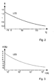
- the output power d of an LED generally decreases with increasing age. 3 shows a typical aging curve of a light-emitting diode operated, for example, at 50 mA.
- a decrease in the transmission power after, for example, 10 4 hours to, for example, 70% can be expected, despite the pre-aging already occurring during production.
- the compensation LED is only a small part of that of the transmit LED emitted light must compensate, it is in the circuit described above also operated with a lower power than the transmitter diode. This leads in the first place Line for different aging of the LEDs. A faster aging of the However, the transmission LED compared to the compensation LED leads to a change in the long term the compensation power and thus an error in the output signal.
- One method of equalizing this aging is to shade the compensation LED to the extent that they emit the same amount of radiation, i.e. the same current as that Send LED, is operated. Due to the shadowing only so much light is shining on the photodiode given, as for a complete suppression of the alternating component of the received signal is needed. However, this does not take into account that the reflection properties of the The object to be measured may change, and with it the compensation LED their performance must be adjusted. This leads to different again Stream and thus to a different aging.
- the present invention has the object Basically, a method and an arrangement for measuring a modulated light signal create that are stable to operate even with changing environmental conditions.
- This task is accomplished by a method and an arrangement for measuring a modulated Light signal with the features of claims 1 or 8 solved.
- This optical measurement system essentially does not address the problems mentioned above true, that is, the system is above all temperature-stable and aging-stable.
- the same current is supplied at least according to the time average.
- the time Average value of the current required to generate the further modulated light signal and / or the time average of the current that the at least one LED is supplied changed so that the temporal averages essentially correspond.
- a pulsed one can also be used Electricity can be supplied if a constant peak power is required, provided this current is preferably supplied during the measurement breaks.
- LEDs especially if they come from the same batch, show the same aging curves, if they are operated under the same environmental conditions.
- a stream through a light emitting diode can be a direct current and within certain limits the average value a pulsed current can be assumed. The latter applies to pulse frequencies, at which on average have no significant heat jumps in the LED chip between the pulse and Pause occur. This can usually be expected from a frequency of approx. 10 kHz.
- control dynamics can also be activated the actually decisive signal range can be adjusted by using a fixed Value is superimposed on the control signal required for the compensation. So “focused” the system does not rely on a possibly static value to compensate for a first, not changing reflection, but tunes to the actual regulation on the minor significant changes in reflection.
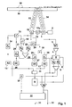
- Figure 1 shows a circuit diagram for eliminating aging and temperature-dependent Changes to optical measuring systems, in particular according to the reflection or transmission principle work to measure a modulated light signal. Arrangement and procedure are described below with regard to a measuring arrangement, e.g. a topping 36 can detect on a disc 35, as it e.g. on a windshield one Vehicle can occur. However, this example does not limit the possible uses of the system, because the same procedure and arrangement for everyone any other use of such a measuring system can be used.
- At least one - but possibly also several - emitting the modulated light signal Light-emitting diodes 10 and at least one receiver 1 are provided for receiving the light signal.
- the light signal from the light emitting diodes is combined with another modulated light signal compensated so that essentially a constant light signal is present at the receiver 1.
- the temporal mean value of the current which is for the generation the further modulated light signal is required, and / or the temporal mean of the current that is supplied to the at least one light-emitting diode 10 is changed that the time averages essentially correspond. To achieve this, becomes a second to the current that is supplied to the at least one light-emitting diode 12 Electricity added.
- the at least one light-emitting diode 12 is as Compensation LED designed to generate the compensating, modulated light signal.
- the compensation LED 12 thus sends out the further modulated light signal, whereby the average current of the light-emitting diode designed as a transmission LED 10 and the Average current of the compensation LED is always approximately the same size by means of a control are regulated.
- additional transmitter LEDs or receivers can be provided if necessary if there is a correspondingly even power supply to the transmitter LEDs is ensured.
- light-emitting diode is used in this application as a synonym for light sources used that change their properties depending on age and / or temperature. Instead of In this respect, light emitting diodes can in particular also be a laser diode or a laser be used.
- the modulated light signal is preferably compared to the further, continuously readjusted one and modulated light signal out of phase.
- the same modulation is used for a transmit LED 10 and a compensation LED the phase shift ideally 180 °.
- the modulated The light signal of the at least one light-emitting diode 10 is reflected by an object, backscattered or transmitted through a transmission area.
- the temporal changes are used to eliminate the age-related changes in state Average values of the transmit LED 10 and the compensation LED 12 here over one each Current mirror 19, 20 recorded separately and after respective low-pass filtering 21, 22 with one another compared. Without any further measures, the time average of the current of the compensation LED becomes 12 usually less than the current of the transmit LED 10. This difference is used to control an additional DC component in the compensation LED 12 evaluated.
- the control 24, 25 comes into action until both mean values of the Currents in LED 10 and LED 12 have the same value. With an additional direct current the emitted pulsed light portion is not by the compensation LED 12 affected.
- the regulated, additional constant light component leads to the same aging, or at the same housing temperature for a thermally identical behavior of LED 10 and LED 12.
- the emitted constant light component on the other hand has no influence on the Measurement, since it is equivalent to extraneous light, which is known to have no influence on the Measurement. This means that the influence of aging and temperature on the measuring section is almost complete locked out.
- the transmit LED 10 and the compensation LED 12 each have their own, relative to one another oppositely regulated DC component supplied. This is useful if the transmission power the transmit LED 10 regulated under the transmit power of the compensation LED 12 can be e.g. with a symmetrical arrangement of transmit LED and compensation LED towards a reflective element.
- a second, permanently set control value is used in parallel with the actual control LED power control used.
- This value takes into account the first, unchangeable Reflection and therefore need not be regulated.
- a regulation of this value makes however, sense if e.g. the control value of the second, smaller reflection reaches values at which he could fall outside of the control range.
- this second control value used to e.g. to reference the first rule value. This can e.g. necessary if a further reflection is to be expected for a given reflection and the full dynamic range of the control should be used. Then the first control value can be changed to a predetermined value by changing the second control value Value.
- Fig. 1 represents an embodiment a complete optical control loop with aging and temperature compensation Furthermore, a pre-setting of a first, fixed Compensation value enabled.
- Clock generator 9 generates e.g. rectangular signal voltage. At the output of the signal inversion stage 11 there is a non-inverted and an inverted signal. The non-inverted The signal is generated via driver stage 17 and control stage 16 and via addition stage 18 the transmission LED 10 fed. The LED current can be detected by means of current mirror 20. Control level 16 is not absolutely necessary, but can be used for large changes in reflection increase the dynamic range of the optical detection.
- the transmit LED 10 transmits a clocked light beam 33 as a light signal, which in the exemplary embodiment is at least one penetrates translucent disc 35 for the radiation emitted by the transmitting LED and is reflected on the surface by the particles of the covering 36.
- the inverted signal of the signal inverting stage 11 is via the driver stage 15, the control stage 14 and the addition stage 13 of the compensation LED 12, which thus the Light path 12a generated.
- the current of the compensation LED can be recorded.
- the photodiode 1 receives the reflected light beam 34.
- For photocurrent compensation can be a series resistor, a gyrator, an inductor or in the circuit arrangement 2 similar can be used.
- a correspondingly operated one can also be used LED are used.
- the high pass 3 separates the high-frequency signal voltages from the constant light signal voltage.
- the synchronous demodulator After appropriate amplification in the preamplifier 4, the synchronous demodulator generates 5 at its outputs two signal components, each of the light paths 12a and the light beam coming from the object or coming from a transmission area 34 are assigned. Those still present at the outputs of the synchronous demodulator 5 higher-frequency signal components are cut off in the low-pass filters 6 and 7, the individual signals of the light paths 12a and 33/34 thus cleaned become the comparator 8 fed.
- This can e.g. be an operational amplifier. Stand at its exits two control signals that are inverted to each other. With the first control signal Control stage 14 for controlling compensation LED 12 is controlled via addition stage 37.
- control stage 16 is used to control the transmit LED 10 controlled.
- the two light outputs are regulated 12a and 34 in the manner that both output signals of the synchronous demodulator 5 essentially are exactly the same, ie essentially have no difference from each other.
- the control is adjusted accordingly quickly, so that even the smallest deviations of the two light paths to each other are immediately corrected without delay. This means, that there is no isochronous alternating signal at the photodiode 1, the circuit is therefore insensitive to extraneous light.
- the output signal 32 for the covering 36 is by means of the comparator 29, which e.g. a subdued Operational amplifiers can be made from the two at the outputs of the synchronous demodulator 5 pending control signals are formed.
- the regulation of the transmission LED 10 is not absolutely necessary, it can also be based on one fixed value. In this case, only the compensation LED is regulated.
- the transmit LED 10 will typically transmit at a higher power than that Compensation LED 12. Since the light path 12a directly from the compensation LED 12 to Leads photodiode 1, the compensation LED requires less power than the transmit LED, which sends the light into a much longer measuring distance. That’s why the transmit LED to a much earlier aging than with the compensation LED. A however, earlier aging of the transmit LED 10 would result in a change in the output signal 32 lead.
- each of the transmit and compensation LEDs Current measuring circuit in the form of a current mirror 19, 20 determines the current transmission current.
- the output values of these current mirrors are in the low-pass filters 21, 22 from the high-frequency Shares of the transmit clock signal exempt. There is a value at each of their outputs, which corresponds to the time average of the current through the respective LED.
- the comparator 23 the two mean values are compared with each other.
- the comparator 23 gives two outputs inverted against each other each a control signal for the control stages 24, 25.
- These control stages add up from a current source 26, 27, preferably a direct current source via the addition stages 13 and 18 each a direct current in addition to the signal current to the LEDs. If only one LED is controlled, only one control stage is required. This control is designed to be the average over time of the current of the transmit LED 10 and the compensation LED 12 as exactly as possible. Thereby ensures that both LEDs age at the same rate. The same average current continues to the same temperature behavior.
- the control unit 30 With her controlled by the control unit 30 to at least one of the regulated light paths into which one of the modulated light signals is irradiated, another value regardless of the Control loop of the control is added to compensate for the extraneous light that the Output signal 32 influenced.
- the other value can be a fixed value for the compensation LED 12 can be specified in addition to the variable value from the comparator 8.
- the variable value can be referenced to this fixed predetermined value.
- the fixed value is e.g. set so if there is no topping 36 on the disc 35 the variable value 32 a predetermined value e.g. 1 V receives. at deposit on the disc 35, this value can then e.g. except e.g. 3 V rise.
- the further value can also be readjusted depending on further parameters become.
- the control unit 30 also receives the output signal 32 from the comparator 29 Exceeding or falling below the output signal 32 above or below a predetermined A corrected addition signal can be supplied to the addition stage 37.
Abstract
Description
Die Erfindung betrifft ein Verfahren und eine Anordnung zum Messen eines modulierten
Lichtsignals, insbesondere mit das Lichtsignal aussendenden Leuchtdioden nach dem Oberbegriff
der Ansprüche 1 oder 8. Der Begriff Leuchtdiode wird im Rahmen dieser Anmeldung
allerdings als Synonym für Lichtquellen verwendet, die alterungs- und/oder temperaturabhängig
ihre Eigenschaften verändern. Anstelle von Leuchtdioden kann insofern insbesondere
auch eine Laser-Diode oder ein Laser verwendet werden.The invention relates to a method and an arrangement for measuring a modulated
Light signal, in particular with light emitting diodes emitting the light signal according to the preamble
of
Anordnung und Verfahren werden im Folgenden im Hinblick auf eine Messanordnung beschrieben, die z.B. einen Belag auf einer Scheibe erfassen kann, wie er z.B. auf einer Windschutzscheibe eines Fahrzeugs auftreten kann. Dieses Beispiel beschränkt jedoch nicht die Anwendungsmöglichkeiten des Systems, da das Verfahren und die Anordnung auch für jeden beliebigen Einsatz eines optischen Messsystems eingesetzt werden kann.The arrangement and method are described below with regard to a measuring arrangement, e.g. can detect a coating on a disc, such as e.g. on a windshield of a vehicle can occur. However, this example does not limit the Possible applications of the system, since the procedure and the arrangement also for everyone any use of an optical measuring system can be used.
Optische Messsysteme wie z.B. Reflexionssensoren arbeiten nach dem Prinzip der gepulsten Lichtaussendung unter Reflexion und Empfang des reflektierten Signals. Ähnliches gilt für das Transmissionsprinzip. Bei gleichbleibender Reflexion bzw. Transmission treten drei Störgrößen besonders in Erscheinung:
- Umgebungslichteinflüsse auf das Empfangssignal
- Alterung der LED und der Photodiode
- Temperaturabhängigkeit der LED und der Photodiode
- Ambient light influences on the received signal
- Aging of the LED and the photodiode
- Temperature dependence of the LED and the photodiode
Fremdlicht beeinflusst die Sensitivität einer Photodiode dergestalt, dass hohe Lichtintensitäten, z.B. direkte Sonneneinstrahlung in die Photodiode, das Empfangssignal eines pulsförmigen Sendesignals in der Amplitude beeinflussen. Dieser Fremdlichteffekt tritt auch bei entsprechender Photostromkompensation, bzw. nachgeregelter Stabilisierung der Photodiode in Erscheinung. Der Amplitudenfehler eines gepulsten Signals zwischen schwacher Umgebungsbeleuchtung und vollem Sonnenlicht (> 100 kLux) kann mehr als 15 % betragen. Der Fremdlichteinfluss macht sich besonders dann bemerkbar, wenn ein Teil des ausgesendeten Signals an Reflektionsstellen wie Kratzern, Schmutz oder Fingerabdrücken eines für Sender und Empfänger ggf. gemeinsam vorhandenen optischen Fensters reflektiert wird. Dieses dann bereits vorhandene Empfangssignal kann durch Fremdlicht in der Amplitude beeinflusst werden. Dadurch wird eine Annäherung eines reflektierenden Gegenstandes vorgetäuscht. Bei einem Annäherungsschalter würde dadurch eventuell eine Fehlfunktion ausgelöst.External light influences the sensitivity of a photodiode in such a way that high light intensities, e.g. direct sunlight into the photodiode, the received signal of a pulse Influence the transmit signal in amplitude. This extraneous light effect also occurs appropriate photocurrent compensation, or readjusted stabilization of the photodiode in appearance. The amplitude error of a pulsed signal between weak ambient lighting and full sunlight (> 100 kLux) can be more than 15%. The influence of extraneous light is particularly noticeable when part of the emitted Signals at reflection points such as scratches, dirt or fingerprints one for The transmitter and receiver, if any, are present together with the optical window reflected. This received signal, which is then already present, can be amplified by extraneous light to be influenced. This makes an approximation of a reflective object faked. This could cause a proximity switch to malfunction triggered.
Im Gegensatz zu diesen Fremdlichteinflüssen, die auch plötzlich auftreten können, macht sich in der Regel ein Temperaturfehler von LED und/oder Photodiode nur in größeren Zeitabschnitten von z.B. mehreren Minuten, bemerkbar. Fig. 2 zeigt das typische Temperaturverhalten einer LED. Der Temperatureinfluß auf die LED wirkt sich so aus, dass bei Erwärmung der LED in der Regel die Sendeleistung S abnimmt. Dabei ist es gleichgültig, ob die LED durch äußere Einflüsse oder durch den Betriebsstrom erwärmt wird. Gleiches gilt analog für eine Photodiode. Bei zunehmender Temperatur nimmt die Empfangsleistung ab. Für einen Einsatz mit einem beispielhaften Temperaturumfang von - 20 °C bis + 120°C verändert sich die empfangene Reflexionsleistung im Verhältnis von z.B. > 4 : 1.In contrast to these influences of extraneous light, which can also occur suddenly As a rule, a temperature error of the LED and / or photodiode occurs only in larger periods from e.g. several minutes, noticeable. 2 shows the typical temperature behavior an LED. The temperature influence on the LED has the effect that when heated the LED usually decreases the transmission power S. It does not matter whether the LED is heated by external influences or by the operating current. The same applies analogously for a photodiode. The reception power decreases with increasing temperature. For changed an application with an exemplary temperature range from - 20 ° C to + 120 ° C the received reflection power is in the ratio of e.g. > 4: 1.
Bei einer dynamischen Messung, die nur kurzzeitige Reflexionsänderungen berücksichtigt, kann eine langsame Änderung des Ausgangssignals durch entsprechende elektronische Maßnahmen korrigiert oder ignoriert werden. Soll z.B. die Annäherung einer Hand an eine optische Reflexionslichtschranke detektiert werden, um z.B. eine Beleuchtung einzuschalten, kann ein Schwellwert zur Annäherungsdetektion durchaus langsam nachgeführt werden. Langsame Änderungen des Reflexionssignals werden dadurch nicht berücksichtigt, sondern nur die schnelle Änderung der sich nähernden Hand. Bei einer gewünschten absoluten Messung dagegen hat der Temperaturgang deutlichen Einfluss auf die Messung. Eine genaue Bestimmung des reflektierten Lichts, z.B. zur Bestimmung eines Belages auf einer Scheibe, kann im herkömmlichen Verfahren nur mit besonderen Maßnahmen zur Stabilisierung der Umgebungstemperatur durchgeführt werden. Hierbei wird allerdings die Alterung der optischen Komponenten nicht berücksichtigt.With a dynamic measurement that only takes short-term changes in reflection into account, can slow change of the output signal by appropriate electronic Measures are corrected or ignored. Should e.g. the approach of a hand to one optical reflection light barrier can be detected, e.g. to turn on lighting a threshold value for proximity detection can be adjusted very slowly. This does not take slow changes in the reflection signal into account, but rather just the quick change of the approaching hand. With a desired absolute measurement however, the temperature response has a significant influence on the measurement. An exact Determination of the reflected light, e.g. to determine a coating on a disc, can in the conventional process only with special measures to stabilize the Ambient temperature. Here, however, the aging of the optical Components not taken into account.
Der Effekt der Alterung der optischen Komponenten ist ein weiterer, wesentlich langfristigerer
Effekt. Mit zunehmenden Alter nimmt die Ausgangsleistung d einer LED in der Regel ab.
Fig. 3 zeigt eine typische Alterungskurve einer z.B. mit 50 mA betriebenen Leuchtdiode. Abhängig
vom verwendeten LED-Typ, der Umgebungstemperatur und dem LED-Strom kann
mit einer Abnahme der Sendeleistung nach z.B. 104 Stunden auf z.B. 70% trotz der bereits
bei der Produktion erfolgenden Voralterung gerechnet werden.The effect of the aging of the optical components is another, much longer-term effect. The output power d of an LED generally decreases with increasing age.
3 shows a typical aging curve of a light-emitting diode operated, for example, at 50 mA. Depending on the type of LED used, the ambient temperature and the LED current, a decrease in the transmission power after, for example, 10 4 hours to, for example, 70% can be expected, despite the pre-aging already occurring during production.
Zusammenfassend ist derzeit ein optisches System, das z.B. das Reflexionsprinzip verwendet, nur äußerst schlecht für genaue Absolutwertmessungen einzusetzen. Dies wird jedoch verlangt, wenn unter verschiedensten Umgebungsbedingungen z.B. ein Belag, der sich nur sehr langsam auf einer zu erfassenden Fläche bildet, optisch erfasst werden soll.In summary, there is currently an optical system that e.g. uses the principle of reflection, extremely difficult to use for accurate absolute value measurements. However, this will required if e.g. under various environmental conditions a surface that only forms very slowly on a surface to be recorded, is to be recorded optically.
Aus der dem Oberbegriff der unabhängigen Ansprüche zugrunde liegenden DE 100 01 955 A1 oder der älteren Patentanmeldung DE 101 33 823 ist eine Kompensation des empfangenen Lichtsignals einer Lichtreflexionsstrecke bekannt, bei der die Wechselanteile des empfangenen Lichtsignals ständig zu Null geregelt werden. Dabei wird während der Sendepausen des Sendesignals mit einer zweiten Leuchtdiode über eine zweite Lichtstrecke der Photodiode so viel Licht zugeführt, das an der Photodiode nur ein konstantes Gleichlichtsignal anliegt. Das Nutzsignal ist nicht mehr das Signal der Photodiode, sondern das Regelsignal der zweiten, kompensierenden Leuchtdiode. Der Vorteil dieser Schaltung liegt in der vollständigen Unempfindlichkeit gegenüber Fremdlicht. In dieser Schaltungsanordnung hat auch die Photodiode und der nachfolgende Verstärker keinen Einfluss auf die Messung. Somit lässt sich mit dieser Schaltungsanordnung das erste der drei genannten Probleme, nämlich die Fremdlichtproblematik lösen.From DE 100 01 955 on which the preamble of the independent claims is based A1 or the earlier patent application DE 101 33 823 is a compensation of the received Light signal of a light reflection path is known, in which the alternating components of the received Light signal to be constantly regulated to zero. Doing so during the breaks of the transmission signal with a second light-emitting diode over a second light path of the photodiode fed so much light that only a constant constant light signal at the photodiode is applied. The useful signal is no longer the signal of the photodiode, but the control signal the second, compensating LED. The advantage of this circuit is that it is complete Insensitivity to extraneous light. In this circuit arrangement too the photodiode and the subsequent amplifier have no influence on the measurement. Consequently With this circuit arrangement, the first of the three problems mentioned, namely solve the ambient light problem.
Da in der Regel die Kompensations-LED nur einen kleinen Teil des von der Sende-LED ausgesandten Lichts kompensieren muss, wird sie in der oben beschriebenen Schaltung auch nur mit einer geringeren Leistung betrieben als die Sendediode. Dies führt in erster Linie zu einer unterschiedlichen Alterung der Leuchtdioden. Eine schnellere Alterung der Sende-LED gegenüber der Kompensations-LED führt langfristig jedoch zu einer Veränderung der Kompensationsleistung und somit zu einem Fehler im Ausgangssignal.As a rule, the compensation LED is only a small part of that of the transmit LED emitted light must compensate, it is in the circuit described above also operated with a lower power than the transmitter diode. This leads in the first place Line for different aging of the LEDs. A faster aging of the However, the transmission LED compared to the compensation LED leads to a change in the long term the compensation power and thus an error in the output signal.
Alterungskurven unterschiedlicher Leuchtdioden sind aus der Literatur hinreichend bekannt. Die Alterung hängt vom Typ der LED, dem Strom und der Chiptemperatur ab. Eine LED altert schneller, je höher der Stromfluss , bzw. die Umgebungstemperatur ist.Aging curves of different LEDs are well known from the literature. The aging depends on the type of LED, the current and the chip temperature. An LED is aging faster, the higher the current flow or the ambient temperature.
Eine Methode, diese Alterung zu egalisieren, besteht in der Abschattung der Kompensations-LED in dem Maße, dass sie bei gleich starker Abstrahlung, also gleichen Strom wie die Sende-LED, betrieben wird. Durch die Abschattung wird nur so viel Licht auf die Photodiode gegeben, wie für ein vollständiges Unterdrücken des Wechselanteils des Empfangssignals benötigt wird. Hierbei wird jedoch nicht berücksichtigt, dass die Reflexionseigenschaften des zu messenden Objektes sich ja möglicherweise ändern und somit auch die Kompensations-LED in ihrer Leistung nachgeregelt werden muss. Dies führt wieder zu unterschiedlichen Strömen und somit zu einer unterschiedlichen Alterung. One method of equalizing this aging is to shade the compensation LED to the extent that they emit the same amount of radiation, i.e. the same current as that Send LED, is operated. Due to the shadowing only so much light is shining on the photodiode given, as for a complete suppression of the alternating component of the received signal is needed. However, this does not take into account that the reflection properties of the The object to be measured may change, and with it the compensation LED their performance must be adjusted. This leads to different again Stream and thus to a different aging.
Ausgehend von diesem Stand der Technik liegt der vorliegenden Erfindung die Aufgabe zu Grunde, ein Verfahren und eine Anordnung zum Messen eines modulierten Lichtsignals zu schaffen, die auch bei sich ändernden Umweltbedingungen stabil zu betreiben sind.Starting from this prior art, the present invention has the object Basically, a method and an arrangement for measuring a modulated light signal create that are stable to operate even with changing environmental conditions.
Diese Aufgabe wird durch ein Verfahren und eine Anordnung zum Messen eines modulierten
Lichtsignals mit den Merkmalen der Ansprüche 1 oder 8 gelöst.This task is accomplished by a method and an arrangement for measuring a modulated
Light signal with the features of
Dieses optische Messsystem nimmt die oben genannten Probleme im Wesentlichen nicht wahr, das heißt, das System ist vor allem temperaturstabil und alterungsstabil. Zu diesem Zweck werden die Leuchtdioden innerhalb des Systems, zumindest soweit sie im selben Aufgabenbereich eingesetzt werden, gleichmäßig gealtert, indem ihnen im Wesentlichen der gleiche Strom zumindest dem zeitlichen Mittelwert nach zugeführt wird. Hierzu wird der zeitliche Mittelwert des Stroms, der zur Erzeugung des weiteren modulierten Lichtsignals erforderlich ist, und/oder der zeitliche Mittelwert desjenigen Stroms, der der wenigstens einen Leuchtdiode zugeführt wird, so verändert, dass sich die zeitlichen Mittelwerte im Wesentlichen entsprechen. Bedarfsweise kann in einer weiteren Ausführungsform auch ein gepulster Strom zugeführt werden, falls es auf eine gleichmäßige Spitzenleistung ankommt, sofern dieser Strom vorzugsweise in den Messpausen zugeführt wird.This optical measurement system essentially does not address the problems mentioned above true, that is, the system is above all temperature-stable and aging-stable. To this The purpose of the LEDs within the system, at least as far as they are in the same Task area, aged uniformly by essentially giving them the same current is supplied at least according to the time average. For this, the time Average value of the current required to generate the further modulated light signal and / or the time average of the current that the at least one LED is supplied, changed so that the temporal averages essentially correspond. In a further embodiment, if necessary, a pulsed one can also be used Electricity can be supplied if a constant peak power is required, provided this current is preferably supplied during the measurement breaks.
LEDs, besonders wenn sie aus der gleichen Charge stammen, zeigen gleiche Alterungskurven, wenn sie unter gleichen Umgebungsbedingungen betrieben werden. Als Strom durch eine Leuchtdiode kann ein Gleichstrom sowie in bestimmten Grenzen der Durchschnittswert eines pulsförmigen Stromes angenommen werden. Letzteres gilt für Pulsfrequenzen, bei denen im Durchschnitt keine wesentlichen Wärmesprünge im LED-Chip zwischen Puls und Pause auftreten. Dies ist in der Regel ab einer Frequenz von ca. 10 kHz zu erwarten.LEDs, especially if they come from the same batch, show the same aging curves, if they are operated under the same environmental conditions. As a stream through a light emitting diode can be a direct current and within certain limits the average value a pulsed current can be assumed. The latter applies to pulse frequencies, at which on average have no significant heat jumps in the LED chip between the pulse and Pause occur. This can usually be expected from a frequency of approx. 10 kHz.
Bei einer Ausgestaltung nach den Ansprüchen 6 oder 12 kann zudem die Regeldynamik an
den tatsächlich maßgebenden Signalbereich dadurch angepasst werden, dass ein fester
Wert dem für die Kompensation erforderlichen Regelsignal überlagert wird. Damit "konzentriert
sich" das System nicht auf einen ggf. statischen Wert zur Kompensation einer ersten,
nicht veränderlichen Reflexion, sondern stimmt sich für die eigentliche Regelung auf die
kleineren maßgeblichen Reflexionsänderungen ein.In the case of a configuration according to
Weitere Vorteile ergeben sich aus den weiteren Ansprüchen und der folgenden Beschreibung. Further advantages result from the further claims and the following description.
Im Folgenden wird die Erfindung an Hand von in den Figuren dargestellten Ausführungsbeispielen näher erläutert. Es zeigen:
- Fig. 1
- einen erfindungsgemäßen Schaltplan mit optischer Regelschleife für Alterungs- und Temperaturkompensation,
- Fig. 2
- das typische Temperaturverhalten der Strahlungsintensität S einer Leuchtdiode,
- Fig. 3
- eine typische Alterungskurve einer Leuchtdiode mit der Abnahme d der Strahlungsleistung über der Zeit t.
- Fig. 1
- a circuit diagram according to the invention with an optical control loop for aging and temperature compensation,
- Fig. 2
- the typical temperature behavior of the radiation intensity S of a light-emitting diode,
- Fig. 3
- a typical aging curve of a light emitting diode with the decrease d of the radiation power over time t.
Figur 1 zeigt einen Schaltplan zur Eliminierung von alterungs- und temperaturabhängigen
Änderungen optischer Meßsysteme, die insbesondere nach dem Reflexions- oder Transmissionsprinzip
zum Messen eines modulierten Lichtsignals arbeiten. Anordnung und Verfahren
werden im Folgenden im Hinblick auf eine Messanordnung beschrieben, die z.B. einen Belag
36 auf einer Scheibe 35 erfassen kann, wie er z.B. auf einer Windschutzscheibe eines
Fahrzeugs auftreten kann. Dieses Beispiel beschränkt jedoch nicht die Anwendungsmöglichkeiten
des Systems, da das gleiche Verfahren und dieselbe Anordnung auch für jeden
beliebigen anderen Einsatz eines derartigen Messsystems eingesetzt werden kann.Figure 1 shows a circuit diagram for eliminating aging and temperature-dependent
Changes to optical measuring systems, in particular according to the reflection or transmission principle
work to measure a modulated light signal. Arrangement and procedure
are described below with regard to a measuring arrangement, e.g. a topping
36 can detect on a
Wenigstens eine - ggf. aber auch mehrere -, das modulierte Lichtsignal aussendende
Leuchtdioden 10 und wenigstens ein Empfänger 1 sind zum Empfang des Lichtsignals vorgesehen.
Das Lichtsignal der Leuchtdioden wird mit einem weiteren modulierten Lichtsignal
so kompensiert, dass am Empfänger 1 im Wesentlichen ein Gleichlichtsignal ansteht. Dabei
wird, wie im Folgenden noch erläutert wird, der zeitliche Mittelwert des Stroms, der zur Erzeugung
des weiteren modulierten Lichtsignals erforderlich ist, und/oder der zeitliche Mittelwert
desjenigen Stroms, der der wenigstens einen Leuchtdiode 10 zugeführt wird, so verändert,
dass sich die zeitlichen Mittelwerte im Wesentlichen entsprechen. Um dies zu erreichen,
wird zu dem Strom, der der wenigstens einen Leuchtdiode 12 zugeführt wird, ein zweiter
Strom hinzuaddiert. Im Ausführungsbeispiel ist die wenigstens eine Leuchtdiode 12 als
Kompensations-LED zur Erzeugung des kompensierenden, modulierten Lichtsignals ausgebildet.
Die Kompensations-LED 12 sendet damit das weitere modulierte Lichtsignal aus, wobei
der Durchschnittsstrom der als Sende-LED 10 ausgebildeten Leuchtdiode und der
Durchschnittsstrom der Kompensations-LED mittels einer Regelung stets etwa gleich groß
geregelt sind. Wie erläutert können weitere Sende-LEDs oder Empfänger bedarfsweise vorgesehen
sein, sofern eine entsprechend gleichmäßig gestaltete Stromzufuhr zu den Sende-LEDs
sichergestellt ist. At least one - but possibly also several - emitting the modulated light signal
Light-emitting
Der Begriff Leuchtdiode wird im Rahmen dieser Anmeldung als Synonym für Lichtquellen verwendet, die alterungs- und/oder temperaturabhängig ihre Eigenschaften verändern. Anstelle von Leuchtdioden kann insofern insbesondere auch eine Laser-Diode oder ein Laser verwendet werden.The term light-emitting diode is used in this application as a synonym for light sources used that change their properties depending on age and / or temperature. Instead of In this respect, light emitting diodes can in particular also be a laser diode or a laser be used.
Vorzugsweise ist das modulierte Lichtsignal gegenüber dem weiteren, ständig nachgeregelten
und modulierten Lichtsignal phasenversetzt. Bei gleicher Modulation ist bei einer Sende-LED
10 und einer Kompensations-LED der Phasenversatz idealerweise 180°. Das modulierte
Lichtsignal der wenigstens einen Leuchtdiode 10 wird von einem Objekt reflektiert, rückgestreut
oder durch einen Transmissionsbereich transmittiert.The modulated light signal is preferably compared to the further, continuously readjusted one
and modulated light signal out of phase. The same modulation is used for a transmit
Zur Eliminierung der alterungsbedingten Zustandsänderungen werden gemäß Fig. 1 die zeitlichen
Mittelwerte der Sende-LED 10 und der Kompensations-LED 12 hier über je einen
Stromspiegel 19, 20 getrennt erfasst und nach jeweiliger Tiefpassfilterung 21, 22 miteinander
verglichen. Ohne weitere Maßnahmen wird der zeitliche Mittelwert des Stroms der Kompensations-LED
12 in der Regel geringer sein als der Strom der Sende-LED 10. Dieser Unterschied
wird zur Regelung eines zusätzlichen Gleichstromanteiles in der Kompensations-LED
12 ausgewertet. Die Regelung 24, 25 tritt so lange in Aktion, bis beide Mittelwerte der
Ströme in LED 10 und LED 12 den gleichen Wert haben. Bei einem zusätzlichen Gleichstrom
durch die Kompensations-LED 12 wird der ausgesandte pulsförmige Lichtanteil nicht
beeinflusst. Der geregelte, zusätzliche Gleichlichtanteil führt jedoch zu gleicher Alterung,
bzw. bei gleicher Gehäusetemperatur zu einem thermisch gleichen Verhalten von LED 10
und LED 12. Der ausgesandte Gleichlichtanteil hat aber andererseits keinen Einfluss auf die
Messung, da er Fremdlicht gleichzusetzen ist, das ja bekanntlich keinen Einfluss auf die
Messung hat. Somit ist ein Einfluss von Alterung und Temperatur auf die Messstrecke nahezu
ausgeschlossen.According to FIG. 1, the temporal changes are used to eliminate the age-related changes in state
Average values of the transmit
In Fig. 1 wurde der Sende-LED 10 und der Kompensations-LED 12 je ein eigener, zueinander
entgegengesetzt geregelter Gleichstromanteil zugeführt. Dies ist sinnvoll, wenn die Sendeleistung
der Sende-LED 10 unter die Sendeleistung der Kompensations-LED 12 geregelt
werden kann, z.B. bei einer symmetrischen Anordnung von Sende-LED und Kompensations-LED
gegenüber einem reflektiven Element.In Fig. 1, the transmit
Bei einer periodisch unterbrochenen Messung kann an Stelle des geregelten Gleichstroms auch ein gepulster Strom treten. Dabei ist zu gewährleisten, das der zusätzliche gepulste Strom nicht in die Messperiode fällt, um Fehlmessungen zu vermeiden. Diese Anordnung kann gewählt werden, wenn eine Alterung nicht nur vom Durchschnittsstrom abhängt, sondern auch von einer Spitzenleistung. Wichtig ist jedoch, wie bereits beschrieben, dass beide LED-Ströme im Durchschnitt gleich sind, um den Effekt der Alterung und den Temperatureinfluss auszuschließen.In the case of a periodically interrupted measurement, instead of the regulated direct current also kick a pulsed current. It must be ensured that the additional pulsed Current does not fall in the measurement period to avoid incorrect measurements. This arrangement can be selected if aging does not only depend on the average current, but also also of a top performance. However, as already described, it is important that both LED currents, on average, are equal to the effect of aging and the influence of temperature excluded.
In einigen Fällen kann es vorkommen, das eine erste konstante, nicht veränderliche Reflexion an einer Oberfläche stattfindet. Zu detektieren ist aber eine zweite, wesentlich kleinere Reflexion, z.B. bei einem langsam auftretenden Belag.In some cases there may be a first constant, unchangeable reflection takes place on a surface. However, a second, much smaller one is to be detected Reflection, e.g. with a slowly occurring coating.
Einen Großteil der Regeldynamik der Lichtimpulsleistung der Kompensations-LED wird nun für das Erreichen des statischen Wertes zur Kompensation der ersten, nicht veränderlichen Reflexion verwendet. Die eigentliche Regelung für die zweite, kleinere Reflexionsänderung spielt sich bei auftretenden Belag in einem sehr kleinen Bereich der Regeldynamik ab. Wünschenswert ist aber eine gute Ausnutzung der Regeldynamik, um auch kleinste Änderungen der zweiten, kleineren Reflexionsänderung deutlich zu erfassen. Dies wiederum bedeutet, das der gesamte Regelumfang möglichst nur für die zweite, kleinere Reflexion zur Verfügung stehen soll.Much of the control dynamics of the light pulse power of the compensation LED is now for reaching the static value to compensate for the first, not changeable Reflection used. The actual regulation for the second, smaller change in reflection takes place in a very small area of the control dynamics when the topping occurs. Desirable but is a good use of the control dynamics to make even the smallest changes the second, smaller change in reflection. This in turn means that the entire scope of the rule is only available for the second, smaller reflection should stand.
Dazu wird parallel zur eigentlichen Regelung ein zweiter, fest eingestellter Regelwert zur LED-Leistungsregelung eingesetzt. Dieser Wert berücksichtigt die erste, unveränderliche Reflexion und braucht daher nicht geregelt zu werden. Eine Regelung dieses Wertes macht jedoch Sinn, wenn z.B. der Regelwert der zweiten, kleineren Reflexion Werte erreicht, bei denen er aus dem Regelbereich herausfallen könnte. Weiterhin kann dieser zweite Regelwert genutzt werden, um z.B. den ersten Regelwert zu referenzieren. Dies kann z.B. notwendig werden, wenn bei einer gegebenen Reflexion eine weitere Reflexion zu erwarten ist und hierbei der möglichst volle Dynamikbereich der Regelung genutzt werden soll. Dann kann durch Änderung des zweiten Regelwertes der erste Regelwert auf einen vorbestimmten Wert gesetzt werden.For this purpose, a second, permanently set control value is used in parallel with the actual control LED power control used. This value takes into account the first, unchangeable Reflection and therefore need not be regulated. A regulation of this value makes however, sense if e.g. the control value of the second, smaller reflection reaches values at which he could fall outside of the control range. Furthermore, this second control value used to e.g. to reference the first rule value. This can e.g. necessary if a further reflection is to be expected for a given reflection and the full dynamic range of the control should be used. Then the first control value can be changed to a predetermined value by changing the second control value Value.
Im Folgenden wird die in Fig. 1 dargestellte Schaltung beschrieben. Fig. 1 stellt als Ausführungsbeispiel eine komplette optische Regelschleife mit Alterungs- und Temperaturkompensation dar. Weiterhin wird in der Schaltung auch eine Voreinstellung eines ersten, festen Kompensationswertes ermöglicht.The circuit shown in FIG. 1 is described below. Fig. 1 represents an embodiment a complete optical control loop with aging and temperature compensation Furthermore, a pre-setting of a first, fixed Compensation value enabled.
Taktgenerator 9 erzeugt eine z.B. rechteckförmige Signalspannung. Am Ausgang der Signalinvertierungsstufe
11 steht ein nicht invertiertes und ein invertiertes Signal an. Das nicht invertierte
Signal wird über Treiberstufe 17 und Regelstufe 16 und über die Additionsstufe 18
der Sende-LED 10 zugeführt. Mittels Stromspiegel 20 kann der LED-Strom erfasst werden.
Die Regelstufe 16 ist nicht unbedingt notwendig, kann jedoch bei großen Reflexionsänderungen
den Dynamikbereich der optischen Erfassung vergrößern. Die Sende-LED 10 sendet
einen getakteten Lichtstrahl 33 als Lichtsignal aus, das im Ausführungsbeispiel eine zumindest
für die von der Sende-LED ausgesandte Strahlung translucente Scheibe 35 durchdringt
und an der Oberfläche an den Partikeln des Belags 36 reflektiert wird.
Das invertierte Signal der Signalinvertierungsstufe 11 wird über die Treiberstufe 15, der Regelstufe
14 und der Additionsstufe 13 der Kompensations-LED 12 zugeführt, die damit die
Lichtstrecke 12a erzeugt. Mittels eines zweiten Stromspiegels 19 kann der Strom der Kompensations-LED
erfasst werden.The inverted signal of the
Die Photodiode 1 empfängt den reflektierten Lichtstrahl 34. Zur Photostromkompensation
kann in der Schaltungsanordnung 2 ein Vorwiderstand, ein Gyrator, eine Induktivität oder
ähnliches verwendet werden. An Stelle der Photodiode kann auch eine entsprechend betriebene
Leuchtdiode verwendet werden.The
Der Hochpass 3 trennt die hochfrequenten Signalspannungen von der Gleichlichtsignalspannung.
Nach entsprechender Verstärkung im Vorverstärker 4 erzeugt der Synchrondemodulator
5 an seinen Ausgängen zwei Signalanteile, die jeweils den Lichtstrecken 12a und
dem hier vom Objekt kommenden oder aus einem Transmissionsbereich kommenden Lichtstrahl
34 zugeordnet sind. Die an den Ausgängen des Synchrondemodulators 5 noch vorhandenen
höherfrequenten Signalanteile werden in den Tiefpassfiltern 6 und 7 abgeschnitten,
die so bereinigten Einzelsignale der Lichtstrecken 12a und 33/34 werden dem Vergleicher
8 zugeführt. Dieser kann z.B. ein Operationsverstärker sein. An seinen Ausgängen stehen
zwei Regelsignale an, die zueinander invertiert sind. Mit dem ersten Regelsignal wird
über die Additionsstufe 37 die Regelstufe 14 zur Steuerung der Kompensations-LED 12 angesteuert.
Mit dem zweiten Regelsignal wird die Regelstufe 16 zur Steuerung der Sende-LED
10 angesteuert. Bei so geschlossener Regelschleife regeln sich die beiden Lichtleistungen
12a und 34 in der Art, das beide Ausgangssignale des Synchrondemodulators 5 im Wesentlichen
genau gleich sind, also zueinander im Wesentlichen keinen Unterschied aufweisen.The
Die Regelung wird entsprechend schnell nachgeführt, so dass schon kleinste Abweichungen
der beiden Lichtstrecken zueinander sofort verzögerungsfrei ausgeregelt werden. Dies bedeutet,
das an der Photodiode 1 kein taktsynchrones Wechselsignal anliegt, die Schaltung
somit für Fremdlicht unempfindlich ist.The control is adjusted accordingly quickly, so that even the smallest deviations
of the two light paths to each other are immediately corrected without delay. This means,
that there is no isochronous alternating signal at the
Das Ausgangssignal 32 für den Belag 36 wird mittels des Vergleichers 29, der z.B. ein bedämpfter
Operationsverstärker sein kann, aus den beiden an den Ausgängen des Synchrondemodulators
5 anstehenden Regelsignalen gebildet.The
Die Regelung der Sende-LED 10 ist nicht unbedingt notwendig, sie kann auch auf einen
festen Wert gesetzt werden. In diesem Fall wird nur die Kompensations-LED geregelt.The regulation of the
In dieser Anordnung kann eine Veränderung der Reflexion an einem Belag 36 sehr genau detektiert werden, ohne dass Fremdlicht einen Einfluss hat.In this arrangement, a change in the reflection on a covering 36 can be very precise be detected without extraneous light having an influence.
In der Praxis wird die Sende-LED 10 in der Regel mit einer höheren Leistung senden als die
Kompensations-LED 12. Da die Lichtstrecke 12a direkt von der Kompensations-LED 12 zur
Photodiode 1 führt, benötigt die Kompensations-LED eine geringere Leistung als die Sende-LED,
die das Licht in eine wesentlich längere Messstrecke schickt. Dadurch kommt es bei
der Sende-LED zu einer deutlich früheren Alterung als bei der Kompensations-LED. Eine
frühere Alterung der Sende-LED 10 würde jedoch zu einer Veränderung des Ausgangssignals
32 führen.In practice, the transmit
Um dies zu verhindern, wird an der Sende- sowie der Kompensations-LED über je eine
Strommessschaltung in Form eines Stromspiegels 19, 20 der aktuelle Sendestrom ermittelt.
Die Ausgangswerte dieser Stromspiegel werden in den Tiefpassfiltern 21, 22 von den hochfrequenten
Anteilen des Sendetaktsignales befreit. An ihren Ausgängen steht je ein Wert an,
der dem zeitlichen Mittelwert des Stromes durch die jeweilige LED entspricht. Im Vergleicher
23 werden beide Mittelwerte miteinander verglichen. Der Vergleicher 23 gibt an zwei
gegeneinander invertierten Ausgängen je ein Steuersignal für die Regelstufen 24, 25 aus.
Diese Regelstufen addieren aus einer Stromquelle 26,27, vorzugsweise einer Gleichstromquelle
über die Additionsstufe 13 und 18 je einen Gleichstrom zusätzlich zur Signalstrom
zu den LEDs. Wird nur eine LED geregelt, ist auch nur eine Regelstufe erforderlich.
Diese Regelung ist so ausgelegt, dass sie den zeitlichen Mittelwert des Stroms der Sende-LED
10 und der Kompensations-LED 12 möglichst auf exakt gleichem Wert hält. Dadurch
wird gewährleistet, das beide LEDs gleich schnell altern. Weiterhin führt der gleiche Durchschnittsstrom
zu gleichem Temperaturverhalten. To prevent this, there is one on each of the transmit and compensation LEDs
Current measuring circuit in the form of a
Im Ausführungsbeispiel ist in FIG. 1 eine weitere Additionsstufe 37 enthalten. Mit ihr wird
gesteuert von der Steuereinheit 30 zu wenigstens einer der geregelten Lichtstrecken, in die
eines der modulierten Lichtsignale eingestrahlt wird, ein weiterer Wert unabhängig von der
Regelschleife der Regelung zur Kompensation des Fremdlichts hinzuaddiert wird, der das
Ausgangssignal 32 beeinflusst. Der weitere Wert kann als fester Wert für die Kompensations-LED
12 zusätzlich zum variablen Wert aus dem Vergleicher 8 vorgegeben werden. Mit
diesem fest vorgegebenen Wert kann der variable Wert referenziert werden. Im Ausführungsbeispiel
wird der fest vorgegebene Wert z.B. so eingestellt, das bei fehlendem Belag
36 auf der Scheibe 35 der variable Wert 32 einen vorgegebenen Wert z.B. 1 V erhält. Bei
sich niederschlagendem Belag auf der Scheibe 35 kann dann dieser Wert z.B. bis auf z.B. 3
V ansteigen. Der weitere Wert kann jedoch auch in Abhängigkeit weiterer Parameter nachgeregelt
werden.In the embodiment shown in FIG. 1 contain a
Die Steuereinheit 30 erhält weiterhin vom Vergleicher 29 das Ausgangssignal 32. Bei einer
Über- oder Unterschreitung des Ausgangssignals 32 über oder unter einem vorgegebenen
Wert kann der Additionsstufe 37 ein korrigiertes Additionssignal zugeführt werden. The
- 11
- Photodiodephotodiode
- 22
- PhotostromkompensationPhotocurrent compensation
- 33
- Hochpasshighpass
- 44
- Vorverstärkerpreamplifier
- 55
- Synchrondemodulatorsynchronous
- 66
- TiefpassfilterLow Pass Filter
- 77
- TiefpassfilterLow Pass Filter
- 88th
- Vergleichercomparator
- 99
- Taktgeneratorclock generator
- 1010
- Sende-LEDTransmission LED
- 1111
- SignalinvertierstufeSignalinvertierstufe
- 1212
- Kompensations-LEDCompensation LED
- 1313
- Additionsstufeadder
- 1414
- Regelstufecontrol stage
- 1515
- invertierende Treiberstufe für Wechselsignaleinverting driver stage for AC signals
- 1616
- Regelstufecontrol stage
- 1717
- Treiberstufe für WechselsignaleDriver stage for alternating signals
- 1818
- Additionsstufeadder
- 1919
- Stromspiegelcurrent mirror
- 2020
- Stromspiegelcurrent mirror
- 2121
- TiefpassfilterLow Pass Filter
- 2222
- TiefpassfilterLow Pass Filter
- 2323
- Vergleichercomparator
- 2424
- Stromreglercurrent regulator
- 2525
- Stromreglercurrent regulator
- 2626
- Stromquelle für GleichstromPower source for direct current
- 2727
- Stromquelle für GleichstromPower source for direct current
- 2828
- (entfallen)(Deleted)
- 2929
- Vergleichercomparator
- 3030
- Steuereinheitcontrol unit
- 3131
- Dynamik-korrigiertes AusgangssignalDynamic corrected output signal
- 3232
- Ausgangssignaloutput
- 3333
- Getakteter LichtstrahlClocked light beam
- 3434
- reflektierter Lichtstrahlreflected light beam
- 3535
- (translucente) Scheibe(translucent) disc
- 3636
- Belagcovering
- 3737
- Additionsstufeadder
Claims (12)
dadurch gekennzeichnet, dass der zeitliche Mittelwert des Stroms, der zur Erzeugung des weiteren modulierten Lichtsignals erforderlich ist, und/oder der zeitliche Mittelwert desjenigen Stroms, der der wenigstens einen Leuchtdiode (10) zugeführt wird, so verändert wird, dass sich die zeitlichen Mittelwerte im Wesentlichen entsprechen.Method for measuring a modulated light signal, with an arrangement with at least one light emitting diode (10, 12) emitting the light signal and at least one receiver (1) for receiving the light signal, the light signal of the light emitting diodes being compensated with a further modulated light signal in such a way that on Receiver (1) essentially has a constant light signal,
characterized in that the temporal mean value of the current, which is required to generate the further modulated light signal, and / or the temporal mean value of that current, which is supplied to the at least one light-emitting diode (10), is changed such that the temporal mean values in the Essentially correspond.
dadurch gekennzeichnet, das der zeitliche Mittelwert des Stroms, der zur Erzeugung des weiteren modulierten Lichtsignals erforderlich ist, und/oder der zeitliche Mittelwert desjenigen Stroms, der der wenigstens einen Leuchtdiode (10) zugeführt wird, einander im Wesentlichen entsprechen.Arrangement for measuring a modulated light signal, with at least one light emitting diode (10, 12) emitting the light signal and at least one receiver (1) for receiving the light signal, as well as with a control with which the light signal of the light emitting diodes is compensated with a further modulated light signal that essentially (1) a constant light signal is present at the receiver,
characterized in that the temporal mean value of the current required to generate the further modulated light signal and / or the temporal mean value of the current supplied to the at least one light-emitting diode (10) essentially correspond to one another.
Applications Claiming Priority (2)
| Application Number | Priority Date | Filing Date | Title |
|---|---|---|---|
| DE10256429 | 2002-12-02 | ||
| DE2002156429 DE10256429A1 (en) | 2002-12-02 | 2002-12-02 | Method and arrangement for measuring a modulated light signal |
Publications (1)
| Publication Number | Publication Date |
|---|---|
| EP1426783A1 true EP1426783A1 (en) | 2004-06-09 |
Family
ID=32308954
Family Applications (1)
| Application Number | Title | Priority Date | Filing Date |
|---|---|---|---|
| EP03027251A Withdrawn EP1426783A1 (en) | 2002-12-02 | 2003-11-28 | Method and device to measure an modulated light signal |
Country Status (2)
| Country | Link |
|---|---|
| EP (1) | EP1426783A1 (en) |
| DE (1) | DE10256429A1 (en) |
Cited By (4)
| Publication number | Priority date | Publication date | Assignee | Title |
|---|---|---|---|---|
| WO2012155870A1 (en) * | 2011-05-13 | 2012-11-22 | Balluff Gmbh | Method for operating a distance sensor and device for carrying out the method |
| WO2015025014A1 (en) * | 2013-08-22 | 2015-02-26 | Elmos Semiconductor Ag | Interference-compensated device for measuring an optical signal transmission path |
| WO2015025009A1 (en) * | 2013-08-22 | 2015-02-26 | Elmos Semiconductor Ag | Method for calibrating an apparatus for measuring an optical signal transmission path |
| EP3124993A1 (en) | 2013-08-22 | 2017-02-01 | ELMOS Semiconductor Aktiengesellschaft | Disturbance-compensated device for measuring an optical signal transfer route |
Families Citing this family (8)
| Publication number | Priority date | Publication date | Assignee | Title |
|---|---|---|---|---|
| DE102004011780A1 (en) | 2004-03-09 | 2005-10-27 | Gerd Reime | Access control device |
| DE502008001809D1 (en) | 2007-09-12 | 2010-12-30 | Behr Hella Thermocontrol Gmbh | Sensor unit for installation in vehicles |
| EP2159600A1 (en) | 2008-08-28 | 2010-03-03 | ELMOS Semiconductor AG | Electro-optical detector for recognising the presence and/or proximity of an object |
| DE102010028967A1 (en) * | 2010-04-26 | 2011-10-27 | Balluff Gmbh | Optical sensor device |
| US9300397B2 (en) | 2013-02-27 | 2016-03-29 | Elmos Semiconductor Ag | Multifunctional optical micro sensor system |
| WO2014131385A1 (en) * | 2013-02-27 | 2014-09-04 | Elmos Semiconductor Ag | Multifunctional optical micro sensor system |
| DE102014017237A1 (en) | 2014-11-21 | 2016-05-25 | Mechaless Systems Gmbh | Measuring system for energy-saving optical distance measurement |
| DE102018222049A1 (en) * | 2018-12-18 | 2020-06-18 | Ibeo Automotive Systems GmbH | Device for operating a light source for optical transit time measurement |
Citations (2)
| Publication number | Priority date | Publication date | Assignee | Title |
|---|---|---|---|---|
| US5386111A (en) * | 1993-10-08 | 1995-01-31 | Zimmerman; H. Allen | Optical detection of water droplets using light refraction with a mask to prevent detection of unrefracted light |
| DE10001955A1 (en) * | 2000-01-18 | 2001-07-19 | Gerd Reime | Optoelectronic switch evaluates variation in received light signal for operating switch element when movement of switch operating object conforms to given movement pattern |
Family Cites Families (2)
| Publication number | Priority date | Publication date | Assignee | Title |
|---|---|---|---|---|
| US6118383A (en) * | 1993-05-07 | 2000-09-12 | Hegyi; Dennis J. | Multi-function light sensor for vehicle |
| DE10107110A1 (en) * | 2001-02-14 | 2002-08-29 | Alcatel Sa | Transmitter for generating optically coded signals, method for generating optically coded signals and transmission system |
-
2002
- 2002-12-02 DE DE2002156429 patent/DE10256429A1/en not_active Ceased
-
2003
- 2003-11-28 EP EP03027251A patent/EP1426783A1/en not_active Withdrawn
Patent Citations (2)
| Publication number | Priority date | Publication date | Assignee | Title |
|---|---|---|---|---|
| US5386111A (en) * | 1993-10-08 | 1995-01-31 | Zimmerman; H. Allen | Optical detection of water droplets using light refraction with a mask to prevent detection of unrefracted light |
| DE10001955A1 (en) * | 2000-01-18 | 2001-07-19 | Gerd Reime | Optoelectronic switch evaluates variation in received light signal for operating switch element when movement of switch operating object conforms to given movement pattern |
Cited By (7)
| Publication number | Priority date | Publication date | Assignee | Title |
|---|---|---|---|---|
| WO2012155870A1 (en) * | 2011-05-13 | 2012-11-22 | Balluff Gmbh | Method for operating a distance sensor and device for carrying out the method |
| US9389310B2 (en) | 2011-05-13 | 2016-07-12 | Balluff Gmbh | Method for operating a distance sensor and device for carrying out the method |
| WO2015025014A1 (en) * | 2013-08-22 | 2015-02-26 | Elmos Semiconductor Ag | Interference-compensated device for measuring an optical signal transmission path |
| WO2015025009A1 (en) * | 2013-08-22 | 2015-02-26 | Elmos Semiconductor Ag | Method for calibrating an apparatus for measuring an optical signal transmission path |
| CN105474036A (en) * | 2013-08-22 | 2016-04-06 | 艾尔默斯半导体股份公司 | Method for calibrating an apparatus for measuring an optical signal transmission path |
| EP3124993A1 (en) | 2013-08-22 | 2017-02-01 | ELMOS Semiconductor Aktiengesellschaft | Disturbance-compensated device for measuring an optical signal transfer route |
| CN105474036B (en) * | 2013-08-22 | 2017-09-12 | 艾尔默斯半导体股份公司 | Method for calibrating the device for being used to measure optical signalling transmission section |
Also Published As
| Publication number | Publication date |
|---|---|
| DE10256429A1 (en) | 2004-06-24 |
Similar Documents
| Publication | Publication Date | Title |
|---|---|---|
| DE19902319B4 (en) | Scattered light fire detectors | |
| EP0482006B1 (en) | Dirt sensor for panes in motor vehicles | |
| EP1426783A1 (en) | Method and device to measure an modulated light signal | |
| DE19882819B4 (en) | Optical receiving device | |
| DE102004055678B4 (en) | Optical navigation device with driver circuit for a laser and optical navigation method | |
| EP2418512A1 (en) | Optoelectronic measuring assembly with compensation for external light sources | |
| DE2847182B2 (en) | Method for modulation current regulation of laser diodes | |
| DE2841433A1 (en) | PRE-CURRENT CONTROL OF LASER DIODES | |
| DE4434666A1 (en) | sensor | |
| EP1480015B1 (en) | Method and device for measuring a modulated light signal | |
| DE102011054912A1 (en) | Dual laser power level control and calibration system for burst mode and continuous mode transmitters | |
| EP1152259A2 (en) | Optical rangefinder | |
| DE112010004476T5 (en) | Receiving circuit for visible light | |
| DE2401906C3 (en) | Device for measuring visibility in a measurement area | |
| DE2932990A1 (en) | METHOD AND CIRCUIT FOR CONTROLLING A DEVICE THAT GIVES A SIGNAL OR RADIATION | |
| WO2022048862A1 (en) | Optical surround sensor with compensation of the ambient light | |
| DE2730056A1 (en) | Light emitter with laser diode control - uses detector output signal and has circuit providing output and bias control signals for diode | |
| DE102020125270A1 (en) | LIDAR SYSTEM AND ITS CONTROL PROCEDURE | |
| DE102008010446A1 (en) | Method and optical sensor arrangement for detecting a measured variable of a medium, in particular for turbidity measurement | |
| DE102010013751A1 (en) | Device for measuring distance between transceiver and target in industrial application, has evaluating device scanning light pulses with respect to phase shifts, where pulses are transmitted by transmitter at certain pulse repetition rate | |
| DE112011100843B4 (en) | Phase control device for a laser light pulse | |
| DE60312157T2 (en) | TECHNIQUES FOR PRELOADING LASERS | |
| DE10393677B4 (en) | Method for setting a target wavelength for an optoelectronic assembly and optoelectronic assembly | |
| DE10138154C2 (en) | Method and device for increasing the long-term operational reliability of a fiber optic interferometer | |
| EP0886252A1 (en) | Optical smoke sensor operating by the extinguish principle |
Legal Events
| Date | Code | Title | Description |
|---|---|---|---|
| PUAI | Public reference made under article 153(3) epc to a published international application that has entered the european phase |
Free format text: ORIGINAL CODE: 0009012 |
|
| AK | Designated contracting states |
Kind code of ref document: A1 Designated state(s): AT BE BG CH CY CZ DE DK EE ES FI FR GB GR HU IE IT LI LU MC NL PT RO SE SI SK TR |
|
| AX | Request for extension of the european patent |
Extension state: AL LT LV MK |
|
| 17P | Request for examination filed |
Effective date: 20041204 |
|
| AKX | Designation fees paid |
Designated state(s): AT BE BG CH CY CZ DE DK EE ES FI FR GB GR HU IE IT LI LU MC NL PT RO SE SI SK TR |
|
| 17Q | First examination report despatched |
Effective date: 20080128 |
|
| STAA | Information on the status of an ep patent application or granted ep patent |
Free format text: STATUS: THE APPLICATION IS DEEMED TO BE WITHDRAWN |
|
| 18D | Application deemed to be withdrawn |
Effective date: 20080808 |