TECHNICAL FIELD
-
The present invention relates generally to communications, and more
particularly to a communications scheme that facilitates handover in a wireless
communications network.
BACKGROUND OF THE INVENTION
-
Wireless communication systems have become increasingly popular for
many applications and types of information, including voice and data communications.
Such communication systems are designed to communicate information in a
transparent manner, with each end user (e.g., communication equipment, such as
terminals or base stations) generally being responsible for ensuring that the data
ultimately delivered is in a desired form. An advantage of wireless communication is the
mobility of communications equipment.
-
Many wireless communications systems employ a layered architecture for
digital communication systems, such as based on the International Organization for
Standardization reference model for Open Systems Interconnection (referred to as the
"OSI Reference Model"). The OSI Reference Model provides a standard to facilitate
connecting open systems; namely, systems that are open for communication with other
systems. The OSI model has seven layers, each of which performs a well-defined
function. The layers include a physical layer, a data link layer, a network layer, a
transport layer, a session layer, a presentation layer and an application layer.
-
Due to the mobility of communications equipment and satellite stations, in
operation, it is often necessary to pass signaling from one base station or platform to a
next base station, which event is referred to as a handover. Typically, handover occurs
as part of bi-directional communication between the network and the terminal
equipment that is being handed over to a new platform or frequency. Such bi-directional
communication is usually implemented via high-level communications in the
OSI communications model, such as at the network layer or other higher layer. The
network layer handover usually requires several messages to be exchanged in
sequence between the network and the terminal being handed over. This message
exchange can cause considerable delay in achieving the handover. Additionally,
because the data in the message exchange is higher level data (e.g., network layer
data), the messages are processed by the network and terminals in order to implement
the handover event. Accordingly, undesirable processing delays also can accompany
such handover, which can further tie up system resources. The delays become even
more significant when there are increased propagation delays due to such signaling
between the terminals being handed over and the network.
-
While a network layer handover is generally manageable for handover
events for small numbers of terminal, the messaging and processing delays associated
with network level handover tend to become even more pronounced for mass handover
events. A mass handover event corresponds to a situation when a relatively large
number of terminals are being handed over concurrently. A mass handover event can
occur, for example, when a communications platform being used by a plurality of
terminals is being replaced by another platform.
SUMMARY OF THE INVENTION
-
The following presents a simplified summary of the invention in order to
provide a basic understanding of some aspects of the invention. This summary is not
an extensive overview of the invention. It is intended to neither identify key or critical
elements of the invention nor delineate the scope of the invention. Its sole purpose is to
present some concepts of the invention in a simplified form as a prelude to the more
detailed description that is presented later.
-
The present invention relates generally to a handover scheme for a
wireless communications network. The handover is implemented utilizing low-level
synchronization mechanisms, such as part of the data link layer, which enable at least
some of the terminals to adjust timing and synchronize communications with the next
platform. Because higher level communications, such as can occur at the network layer
or higher, are not required to implement the handover, the handover that can be
implemented efficiently, especially for mass handover events. Thus, handover from a
first or pre-handover communications platform to a next or post-handover platform can
occur concurrently for plural communications terminals.
-
According to one aspect, handover can be implemented in a wireless
communications network having a plurality of terminals synchronized for network
communications via a pre-handover base platform. The handover occurs, for example,
by terminals transmitting a signal having timing information, such as can be transmitted
in a predetermined slot or channel of a wireless communications framework. Each
terminal can estimate an expected time for receiving a response to the transmitted
signal, such as corresponding to the pre-handover platform. The terminals receive a
response to the transmitted signal at some time and comparing this to the expected
time. The terminals then adjust timing for subsequent signal transmissions based on
the comparison. In some cases, a platform (e.g., the pre-handover platform) can
broadcast a network message to the terminals that are to be handed over indicative of a
handover event. The content of such broadcast message can vary depending on
system complexity and design requirements, for example.
-
To the accomplishment of the foregoing and related ends, certain
illustrative aspects of the invention are described herein in connection with the following
description and the annexed drawings. These aspects are indicative, however, of but a
few of the various ways in which the principles of the invention may be employed and
the present invention is intended to include all such aspects and their equivalents.
Other advantages and novel features of the invention will become apparent from the
following detailed description of the invention when considered in conjunction with the
drawings.
BRIEF DESCRIPTION OF THE DRAWINGS
-
FIG. 1 illustrates a communications system in a pre-handover condition in
accordance with an aspect of the present invention.
-
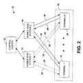
FIG. 2 illustrates the communications system of FIG. 1 implementing
handover in accordance with an aspect of the present invention.
-
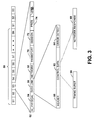
FIG. 3 is an example of a communications model that can be utilized to
implement handover in accordance with an aspect of the present invention.
-
FIG. 4 illustrates a satellite communications system operative to
implement handover in accordance with an aspect of the present invention.
-
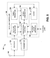
FIG. 5 is a schematic block diagram of a terminal operative to implement
handover in accordance with an aspect of the present invention.
-
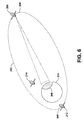
FIG. 6 illustrates an example of a satellite system operative to implement
handover in accordance with an aspect of the present invention.
-
FIG. 7 illustrates an example of the satellite system of FIG. 6 in a another
condition in accordance with an aspect of the present invention
-
FIG. 8 is a flow diagram illustrating a methodology for implementing
handover in accordance with an aspect of the present invention.
DETAILED DESCRIPTION OF INVENTION
-
The present invention relates to handover in a wireless communications
system. The handover is implemented utilizing low-level synchronization mechanisms,
such as part of the data link layer, which enable at least some of the terminals to adjust
timing and synchronize communications with the next platform. Because higher level
communications, such as can occur at the network layer or higher, need not be utilized
to implement the handover, the handover that can be implemented efficiently, especially
for mass handover events involving plural terminals. Thus, handover from a first (pre-handover)
communications platform to a next (post-handover) platform can occur
concurrently for plural communications terminals.
-
FIG. 1 illustrates a communications network 10 operative to implement
handover in accordance with an aspect of the present invention. The network 10
includes plural base stations 12 and 14. As used herein, the terms "base station" and
"platform" are used interchangeably to refer generally to communications equipment
operating a network hub for a set of other communications equipment in the network.
The base stations 12 and 14 can be mobile base stations, such as non-terrestrial
stations (e.g., satellites or aircrafts). Alternatively, the base stations 12 and 14 can be
fixed terrestrial base stations, such as satellite network transceivers distributed about
the network 10.
-
The network 10 also includes a set 16 of one or more terminals 18-20 that
are operative to communicate throughout the network via one or more of the base
stations 12 and 14. The terminals 18-20 can be fixed terrestrial communication stations
(e.g., customer premises equipment (CPE)) or, alternatively, they can be mobile
stations (e.g., terrestrial or airborne). The terminals 18-20 communicate in the network
10 through one or more of the base stations 12 and 14. For purposes of brevity, only
two terminals 18-20 are depicted within the set of terminals 16. It will be understood
and appreciated that there can be any number of one or more terminals in the set 16, as
indicated by the ellipsis between the terminals 18 and 20,
-
The network 10 also includes a control center 22 that controls
communications parameters for the network. The control center 22 can be terrestrial or
non-terrestrial communications equipment. It is also to be appreciated that the control
center 22 can be integrated into one of the base stations 12 or 14 as well as in one or
more of the terminals 18-20. Alternatively, the control center 22 can be a terrestrial
control center and the satellites operate as repeaters enabling communications between
the terminals 18-20 and the control center.
-
By way of example, the control center 22 stores and maintains a data
space or data structure corresponding to network operation and status of network
equipment. The data structure includes, for example, status information associated with
the individual network components 12-20, such as framing and time slot information,
identification information and the like. The control center 22 also is operative to
implement controls in the network 10 based on the status, location information or other
network-related parameters. The network control center 22 further can employ various
processes, such as to allocate and manage network resources (e.g., frequency and
bandwidth), to manage communications between active network equipment as well as
to authenticate new equipment entering the network 10.
-
It is to be understood and appreciated that control center 22 can signal
equipment within the network, including one of the base stations 12 or 14, the terminal
equipment 18-20, or both, to initiate mode changes, such as including a handover.
Alternatively or additionally, the base station 12 and/or the equipment itself can be
programmed to implement similar controls, including to initiate a handover event. The
particular functionality implemented at each of the equipment 12-22 generally can be
set as a matter of design choice, such as based on system requirements, processing
capabilities of such equipment and ease of maintaining such equipment, for example.
-
For purposes of ease of explanation, it is assumed that the set 16 of
terminals 18-20 are all active terminals in the network 10 and initially communicate in
the network via the base station 12 (the pre-handover base station). At least one of the
base stations 12 and 14 and/or the terminals 18-20 are movable relative to each other.
Consequently, the present base station 12 may be removed from service, such as being
rotated out of service or otherwise may experience a disruption in service for at least
some of the terminals 18-20. Thus, the network 10 is operative to implement a
handover from one base station 12 to the other base station 14 in accordance with an
aspect of the present invention.
-
By way of example, communications between the terminals 18-20 and the
base station 12 is implemented using a frame-based architecture that includes slots or
sub-slots assigned for communications to and from the respective terminals. For
example, each terminal 18-20 is assigned a unique slot in which to transmit and receive
data according to the communications protocol being implemented in the network 10.
The slots can correspond to time slots, such as for time division multiplexing (TDM),
time division multiple access (TDMA), or to frequencies or channels, such as for
frequency division multiplexing (FDM), frequency division multiple access (FDMA), code
division multiplexing (CDM) or code division multiple access (CDMA). The data
contained in the slots can be transmitted in a layered data protocol, such as according
to the OSI model, to facilitate stable communications of data between processes at the
terminals 18-20 and base station 12.
-
For purposes of brevity and ease of explanation, the following example
assumes a TDMA/TDM physical layer protocol for communications between the
terminals 18-20 and base station 12. Those skilled in the art will understand and
appreciate that other communications protocols could be utilized according to one or
more aspects of the present invention. For example, signals (e.g., downlinks) 24 and
26 from the base station 12 to the terminals 18-20 correspond to TDM links and the
signals 28 and 30 from the terminals to the base stations correspond to TDMA uplinks.
-
By way of further example, using the OSI Reference Model, the data link
(or link) layer generally controls the way messages are sent through the network 10.
The link layer facilitates transparent communication for the network layer and other
higher level layers. The data link layer generally performs three main functions,
including the flow control (e.g., when messages are sent), message delineation and
error detection and control. The flow control function of the link layer includes
synchronizing when a terminal 18 or 20 transmits a message to the base station so as
to be received a the base station within its assigned slot.
-
As a result, the terminals 18-20 are programmed to intermittently or
periodically transmit synchronization information (in the data link layer) to help maintain
synchronization with the base station 12. For example, the terminals 18-20 provide
intermittent or periodic timing information, such as a timing burst, in its assigned time
slot of the TDMA uplinks 28 and 30. The periodic timing burst in the uplinks 28 and 30
operate as requests querying the base station 12 as to whether each respective
terminal is adequately synchronized with the network 10. The network 10 thus can
issue a network response via a return TDM downlink 24 and 26 indicating if timing
adjustments are needed by the respective terminals. Other suitable low-level frame
timing or synchronization information can be contained in the link layer of appropriate
time slots of the TDM downlinks 24 and 26 based on which the respective terminals 18-20
can synchronize to the network. The response from the base station, for example,
can include instructions to advance or retard timing at the respective terminals.
-
In accordance with an aspect of the present invention, the network 10 is
operative to implement handover for the set 16 of one or more active terminals 18-20
from the present or pre-handover base station 12 to a new or post-handover base
station 14. In the frame based communications architecture, the handover is
implemented using low level data, such as the data link layer. As mentioned above, the
data link layer is used to maintain synchronization between the terminals 18-20 and
their associated pre-handover base station 12.
-
FIG. 2 illustrates an example in which the network is handing over
communications for the set 16 of terminals 18-20 from the base station 12 to the base
station 14. Thus, the post-handover station 14 transmits downlink signals 34 and 36 to
the respective terminals 20-18. The control center 22, for example, provides the post-handover
station 14 with requisite data (e.g., framing data, terminal ID's, slot
assignments and so forth) to enable communications between the station and the
terminals. The terminals 18-20 also communicate uplink signals 38 and 40, at least
some of which are received by the post-handover base station 14. As shown by dotted
lines and indicated by adding prime symbols, in certain circumstances, the terminals 18-20
can still send uplink signals 28' and 30' to be received by the pre-handover station
12. Additionally, the station 12 may transmit downlink signals 24' and 26' to the
terminals, such as until handover is completed. The uplink signals 28' and 30' can be
different from the uplink signals 38 and 40, although such transmissions could
alternatively correspond to the same uplink transmissions received by different base
stations 12 and 14.
-
During handover, the synchronization mechanism in the data link layer is
further exploited to implement handover and acquire resources relative to the post-handover
station 14. When operating in the handover mode, for example, the terminals
18-20 can suspend normal data traffic in the signals 38 and 40 and communicate
synchronization information with the station 14. Normal traffic between the post-handover
station 14 and the terminals 18-20 can be resumed, for example, after a
predetermined period of time has expired (e.g., based on empirical studies), after a
predetermined number of frames have been communicated, or after a certain
percentage of the terminals that are being handed over have adequately synchronized
with the new base station.
-
It is to be appreciated that because the set 16 of terminals 18-20 that are
being handed over are already authenticated as users in the network 10 (eg., active
users), the handover can be completed for all or a portion of the terminals based on
their synchronization with the new base station 14. It is possible that the handover may
fail for some of the terminals 18-20 in the set 16 being handed over, such as in a mass
handover event. For example, handover could fail for terminals located near the fringe
of the coverage area for the post-handover base station 14, such as due to parallax
differences. Accordingly, the terminals that are not able to synchronize properly in the
time period permitted, can then implement a network layer handover, as is known in the
art. It will be appreciated that for mass handover, efficiencies and resource
conservation can be achieved by handing over such terminals to the new base station
concurrently in accordance with an aspect of the present invention.
-
The terminals 18-20 being handed over can transition from a normal
active mode to a handover mode. In the normal mode, the terminals communicate
normal traffic between the terminals and the base station 12. In the handover mode,
each of the terminals 18-20 synchronizes with the post-handover station 14. A
transition from the normal active mode to the handover mode can occur at the terminals
18-20 based on concurrent signaling (e.g., of a broadcast message) from the network
10 to the terminals or based on the terminals themselves detecting conditions
corresponding to handover.
-
According to an aspect of the present invention, handover can be
implemented based on the network 10 (e.g., the control center 22) controlling the pre-handover
platform 12 to stop transmitting and the new platform to begin transmitting to
the terminals 18-20. In this scenario, each of the terminals 18-20 receiving a signal
from the post-handover station 14 detects that its frame boundary is out of
synchronization with the expected frame boundary in the received signals 34 and 36.
Additionally or alternatively, the terminals 18-20 may detect a different frame ID from
that expected in the time slot data. It will be appreciated that frame synchronization
may exist, but a given time slot in the signaling 34, 36 may have shifted some integer
number or frames due to the distance between the station 14 and the terminals 18-20.
The direction and amount of such shifting will vary based on the relative position
between the terminals and the station 14 as compared to the pre-handover station 12.
In this case, such slot will have a different frame ID than expected for a transmission
received from the old platform 12 (FIG. 1). When a terminal 18-20 detects such a
framing discrepancy, the terminal can enter its handover mode, according to an aspect
of the present invention, and employ the link layer to implement the desired
synchronization, such as described herein.
-
For a more complex communications arrangement, the network 10 can
implement signaling in the signals 24' and 26' from the pre-handover station 12 to the
terminals 18-20 instructing the terminals to enter their handover mode. The pre-handover
station 12 can broadcast a command to each of the terminals 18-20, such as
a higher level broadcast message (e.g., in the network layer or higher). The broadcast
message enables the terminals to transition from the normal mode to the handover
mode. The complexity and quantity of information contained in the message can vary
as a matter of design choice and processing capabilities. For example, the network
message can alert the terminal equipment that is being handed over that a handover
event is imminent. Additionally or altematively, the network message can provide
estimates of resynchronization parameters to facilitate the handover as well as provide
for more general optimization at the terminals 18-20.
-
By way of further example, the terminals 18-20 can estimate the
resynchronization (e.g., an initial coarse estimate) as a function of position information,
velocity information, or a combination thereof, received in the network handover
message for the post-handover platform. The terminals can subsequently perform finer
synchronization depending upon the accuracy of the initial estimates. The fine
synchronization, in turn, can enable a rapid convergence to synchronization for each
terminal. Those skilled in the art will understand and appreciate various types of other
information that can be included in a network handover message that can facilitate an
estimation of a timing adjustment at each of the terminals being handed over. Typically,
there will be an exchange of one or more messages between the terminals 18-20 and
the post-handover base station 14.
-
By way of further example, a network handover message can also
implement a new frequency scheme or plan, such as to facilitate optimization in
communication between the terminals being handed over and the new base station 14.
For example, because the relative position between the terminals 18-20 being handed
over and the new base station 14 can differ from the arrangement between the
terminals and the prior base station 12, time slots can be reassigned and frequency
resources can be optimized based on adjustments made by the control center 22 of the
network 10. Another aspect of the message can set a duration for the handover mode
in which the terminals are not to transmit or receive user data traffic. The duration can
be a period of time or a set number of frames during which normal data traffic is to be
suspended.
-
In accordance with another aspect of the present invention, in a network in
which the terminals 18-20 have dual channel capabilities, the terminals can continue
transmitting with the old station 12 over one channel and concurrently begin
synchronization with the new station 14 over another channel. This dual transmission
scheme results in an overlap of communication between the old and new platforms,
such that data traffic can be communicated through the old platform until the handover
to the next platform can be completed. The handover for each of the terminals 18-20
can thus occur concurrently or at different times depending on when the terminals are
adequately synchronized with the post-handover station 14. The concurrent multichannel
transmissions by the terminals 18-20 that are being handed over can occur, for
example, concurrently at different frequencies (TDM, TDMA) or at different channels or
codes (COMA). In the messages communicated to the new base station 14, the
terminals 18-20 can send empty frames together with resynchronization information in
the link layer (e.g., timing bursts), as described herein.
-
In order to facilitate synchronization between the terminals 18-20 and the
post-handover base station 14, each of the terminals can itself be programmed and/or
configured to estimate or predict timing adjustments. Each of the terminals 18-20, for
example, can employ an internal clock and predict or estimate a time when each
terminal would have expected a time slot from the pre-handover station 12. When a
terminal receives a response from the post-handover base station 14, the terminal
compares the expected time with the actual received time and, based on the
comparison, adjusts frame timing for the terminal. For example, each terminal can be
programmed to compute a difference between the expected frame timing from the pre-handover
station 12 and the actual frame timing from the post-handover station 14. The
difference corresponds to a timing adjustment that will enable the terminals 18-20 to
synchronize with the post-handover station 14.
-
Additionally, the terminals 18-20 can implement more precise (or finer)
adjustments to help synchronize frame timing based on a network response to each of
the terminals' timing burst. The post-handover station 14 can provide the network
response for each terminal, for example, as link layer synchronization information. The
synchronization information, for example, can indicate in which direction timing should
be adjusted, such as to advance or retard timing. In certain implementations, the
synchronization information in the network response from the station 14 can indicate an
amount (e.g., in microseconds or milliseconds) by which each respective terminal 18-20
should adjust its timing.
-
FIG. 3 is an example of a frame based model, such as can be utilized in a
network operative to implement handover in accordance with an aspect of the present
invention. In this example, a frame 50 includes a plurality of slots S1 through SN, where
N is an integer greater than 1. Each of the slots can be time slots, such as associated
with a time division multiplexing (TDM) or time division multiple access (TDMA),
architecture. It is also to be understood and appreciated that the slots could correspond
to channels or bands, such as associated with code division multiple access, frequency
division multiplexing or frequency division multiple access. Typically, each terminal is
assigned at least one slot in which it can communicate data relative to the base station
with which it is associated in the network. Each slot S1-SN includes a plurality of layers
according to a predefined communications protocol. In the example of FIG. 3, time slot
S3 has been expanded to illustrate various layers contained in the slot according to the
OSI reference model. It is appreciated that each of the other slots in each respective
frame can be similarly configured. Slot S3 and each of the slots includes a guard band
52, which provides a safety margin against symbol interference in the time between
adjacent time slots.
-
Slot S3 also includes a physical layer 54 which provides a protocol that
defines the lowest level of communication between devices in the network, such as to
enable a raw bit stream surface in the network. The next layer is a data link layer 56
which attempts to make the physical raw bit stream of data reliable. Various standards
exist for the data link layer including LLC, HDLC, LAPB, LAPD, to name a few.
-
The principle service provided by the link layer 56 is error detection,
control, and synchronization. By way of example, three common error detection
methods are parity checking, longitudinal redundancy checking, and polynomial
checking (particularly checksum and cyclic redundancy checking). The link layer 56 can
also manage channel access and flow control as well as ensure correct sequence in
transmitted data. It also may correct errors that occur in the physical layer 54 without
using the functions of the upper layers. Thus, the next higher layer, the network layer
58, can assume virtually error-free transmission over the communications link. Also
included in the link layer 56 are framing and synchronization data, such as for providing
flow control of data.
-
In FIG. 3, the link layer has been expanded to show a header 60, control
data 62 and error detection data 64. The header, for example, indicates what type of
control data is being provided at 62. For example, the header 60 can include an ID,
such as a data word, indicating that the control data 62 is to be used for timing or
synchronization of the slot S3 in the frame 50. In particular, the header 60 can also
specify attributes of the synchronization data, such as a timing burst 66. The timing
burst 66, for example, can be utilized for maintenance synchronization. Terminals
perform maintenance synchronization intermittentiy or periodicaiiy to help ensure proper
synchronization of respective time slots in the framing structure used for communication
between a terminal and a base station. Additionally or alternatively, the timing burst 66
can be provided in a handover mode when the terminal is being handed over from a
pre-handover base station and a post-handover station in accordance with an aspect of
the present invention.
-
A base station receiving control data 62 that includes synchronization
data, such as the timing burst 66, can in turn provide a network response 68 to the
timing burst also in the data link layer 56. The network response 68 can specify a
synchronization or timing adjustment to be made by the terminal in order to achieve
proper synchronization with the network. For example, the network response 68 to the
terminal can include an indication to retard or advance its timing accordingly. One or
more exchanges of such messages (timing bursts and network responses) between
each of the terminals being handed over and the post-handover base station can occur
in order to achieve suitable synchronization. This message exchange in conjunction
with timing estimates (or predictions) made by the terminals facilitates synchronization
for handover events according to an aspect of the present invention.
-
When a terminal receives a network response from the base station
indicating that timing should be adjusted, such as advanced or retarded, the terminal
makes a determination as to whether the adjustment is due to a drift in its internal clock
timing or due to a shift in distance such as due to movement of the terminal and/or
movement of the base station. This determination of the basis for the timing adjustment
will vary depending on whether a handover event is being implemented. Specifically,
during handover, the terminal (e.g., operating in the handover mode) can assume that a
timing difference between the actual and predicted timing difference is due to a shift in
the distance between the terminal and the base station. Accordingly, the terminal will
adjust its frame timing when to send the timing burst and usually not adjust its clock.
-
By way of further example, if a terminal detects the beginning of the frame
arrives before expected, indicating an error due to a change in the distance and/or
during a handover event, the terminal adjusts the transmission time in the opposite
direction in which the detected shift in timing occurs. For example, the terminal can
compute a difference between the actual and expected times. Thus, if the beginning of
a frame arrives before expected, based on the predicted timing, the terminal will delay
its transmission according to the computed difference so that the next timing burst does
not arrive early at the base station. As mentioned above, the amount of adjustment can
be based on information provided in the response from the base station or based on
solely upon the computed difference between the actual and predicted transmit times.
Such prediction or estimation by the terminal facilitates resynchronization and handover
in accordance with an aspect of the present invention. It will be appreciated that such
resynchronization is facilitated because the terminal can make a gross (or coarse)
adjustment based on the comparison of the actual and predicted transmit times for the
timing bursts.
-
Referring again to FIG. 3, the network layer 58 generally provides for the
transfer of data between transport entities such as base stations and terminals and/or
the control center. The network service is responsible for establishing, maintaining and
terminating connections across the intervening communications facility, such as
provided by the data link layer 56. The protocol also can include a transport layer 70
that provides a reliable mechanism for the exchange of data between processes in
different systems. The transport layer 70, for example, ensures that units of data are
delivered in an error free sequence. The transport layer 70 also can be concerned with
optimizing the use of network services and providing a desired quality of service to the
session entities, as is known in the art.
-
A session layer 72 can provide a mechanism for controlling the dialogue
between presentation entities. For example, a session layer provides a means for two
presentation entities or processes to establish and use a connection, usually called a
session. The presentation layer 74 offers application programs and terminal handler
programs a set of data transformation services, which can include data translation,
formatting and syntax selection. Finally, an application layer 76 provides a means for
application processes to access the OS! model. The application layer 76 can contain
management functions and other mechanisms to support distributed applications and
other user oriented protocols.
-
FiG. 4 is an example of a communications network 100 operative to
implement handover in accordance with an aspect of the present invention. The
network 100 includes a plurality of non-terrestrial mobile platforms 102, 104 and 106,
which can be space borne base stations (e.g., satellite), air borne base stations (e.g.,
manned or unmanned aircraft) or a combination thereof. A plurality of consumer
premises equipment (CPE) 108, 110 and 112 form a set of CPEs 114, each of which is
programmed and configured to implement a handover in accordance with an aspect of
the present invention. In this example, the CPE 112 operates as a gateway to access
another network 116, such as a computer network (e.g., global network or LAN) or a
telecommunications network (e.g., public telephone switched network (PTSN)). The
network 100 also includes a control center 118, which can be a terrestrial or non-terrestrial
station or can be implemented in one or more of the stations 102-106 or the
CPEs. The control center 118 is programmed and/or configured to manage network
resources as well as control other aspects relating to operation of the network 100.
-
For purposes of example, it assumed that the set of CPEs 106, 108 and
110 are initially communicating with the network 100 via platform 102. The network
assigns each of the CPEs 106-110 to a time slot, and each CPE employs its link layer to
maintain proper synchronization while operating in an associated normal active mode.
Thus, the platform 102 receives data transmitted from each of the CPEs in their
assigned time slots located within respective guard bands in the communications frame.
-
In accordance with an aspect of the present invention, a mass handover
event for the set 114 of CPEs 106-110 is being implemented from the platform 102 to a
next platform, namely platform 104. Such a mass handover event can occur when the
platform 102 the set of terminals 106-110 is to be handed over to the different platform
104. This can occur, for example, as a satellite platform moves in its orbit to a position
where it is unable to communicate with the set 114 of terminals 108-112. Alternatively,
the platform 102 can be removed from service for maintenance or other reasons. For
example, an airborne aircraft operating as a base station for the network 100 may be
rotated out of services for refueling or to perform maintenance.
-
As mentioned above, various approaches can be utilized to implement a
mass handover event according to an aspect of the present invention. Each approach
employs low level synchronization procedures (e.g., in the data link layer) implemented
by each of the terminals 108-112. By way of example, each of the terminals 108-112 is
operative to predict or estimate a time when each of the terminals would have expected
to receive a message (e.g., in the assigned time slot) from the pre-handover platform
102. The terminals 108-112 receive a response from the post-handover platform 104
during a handover event, such as in response to a timing burst. By comparing the
estimated receipt time and the actual time the message is received from the new
platform 104, each of the terminals can compute a difference between the expected
frame timing from the pre-handover platform 102 and the frame timing from the post-handover
platform 104. The computed difference corresponds to a timing adjustment
that enables each of the terminals 108-112 to synchronize with the post-handover
platform 14. The terminals 108-112 can also implement more precise (or finer)
adjustments to help synchronize frame timing, such as based on data contained in a
network response. The network response, which the post-handover platform 104 may
provide as link layer synchronization information, can indicate in which direction and an
amount by which timing should be adjusted for each terminal.
-
By way of further example, a handover event can be initiated in response
to the network 100 (e.g., the control center 118) controlling the pre-handover platform
102 to stop transmitting and the new platform 104 to begin transmitting to the terminals
108-112. In this basic approach, each of the terminals 108-112 detects the handover
event by noticing that its respective frame boundary in received signals is out of
synchronization with the expected frame boundary. Additionally or alternatively, the
terminals 108-112 may detect a different frame ID from that expected in the time slot
data, which can be in addition to a frame shift. When such framing discrepancies are
detected at the terminal 108-112, each terminal can enter its handover mode, according
to an aspect of the present invention, to employ the link layer to implement the desired
synchronization, as described herein.
-
For a more complex communications arrangement, the network 100 can
implement some signaling to instruct the terminals that are to be handed over to enter
the handover mode. Such network messaging can be provided as a higher level
broadcast message (e.g., network layer or higher) that is broadcast to each of the
terminals being handed over. As mentioned above, the complexity and quantity of
information contained in the message can vary as a matter of design choice, processing
capabilities and available resources in the network 100.
-
Additionally or alternatively, in a network in which the terminals 108-112
have dual channel capabilities, the terminals can continue transmitting with the old
platform 102 and concurrently begin synchronization with the new platform 104. This
dual transmission scheme results in concurrent terminal communication with both of the
platforms. Consequently, data traffic can be communicated through the old platform
102 until the handover to the next platform 104 can be completed.
-
While the foregoing example in FIG. 4 has been described as a mass
handover event in which all of the terminals 108-112 are handed over to a common new
platform 104, it will be understood and appreciated that different subsets of the CPEs
108-112 can be handed over to different new platforms. For example, a first subset of
the CPEs can be handed over to the platform 104 and a second group or subset of the
CPEs can be handed over to a different platform 106. Such a split-handover or
allocation of resources may be considered necessary where no single base station is
positioned to provided adequate coverage for the terminals being handed over. For
instance, different subsets of terminals 108-112 can be handed over to different base
stations where the pre-handover satellite 102 is in a highly elliptical orbit that provides
coverage to a large area. In this situation, as the station 102 moves out of service, two
or more other platforms 104-106 (e.g., satellites or aircraft) may be required to provide
adequate service for the set of terminals 106-110.
-
Thus, those skilled in the art will understand and appreciate that by
implementing the handover via synchronization in the data link layer, the individualized
higher-level signaling and associated processing typically required in a conventional
network layer is mitigated. As mentioned above, a broadcast message by the network
100 to all the terminals concurrently can be utilized to facilitate handover in accordance
with an aspect of the present invention.
-
FIG. 5 is an example of a block diagram of a user terminal or CPE system
150 that can be utilized to facilitate handover in accordance with an aspect of the
present invention. The system 150 includes an antenna 152 that can be used to
transmit or receive data relative to the system. While a single antenna 152 is illustrated
in FIG. 5, it is to be appreciated that different antennas could be used for transmitting
received functions. Those skilled in the art will appreciate various antenna
configurations and designs that could be utilized.
-
For an incoming signal, a receiver 154 receives the incoming signal for the
antenna 152 and demodulates the signal to an appropriate electrical signal having
associated data, such as according to the model shown and described in FIG. 3. The
receiver 154 can include a demodulator and various filters operative to provide
demodulated data to a data link controller 156. The receiver 154 thus is programmed
and/or configured to convert the wireless signals to a corresponding electrical signal
according to the particular communications protocol being utilized (e.g., TDM, CDM
etc.). An analog to digital converter (not shown), which can be implemented in the
receiver, in the data link control or as an intervening converter, converts the analog
demodulated signal to digital data.
-
The data link controller 156 is programmed and/or configured to process
and control the data link layer for incoming and outgoing transmissions. In particular,
the data link controller 156 is operative to implement synchronization between the
system 150 and its associated network using information transmitted in the link layer of
the communications model. Such synchronization can include maintenance
synchronization with a currently associated base station. Additionally, such
synchronization can include synchronization with a new (post-handover) base station in
response to a handover event implemented in accordance with an aspect of the present
invention. The data link controller 156 can also include other functions, such as to
implement error detection, error correction and flow control as is known in the art.
-
Referring to the contents of the data link controller 156, it includes a data
link extractor 158 that receives the demodulated (digital) data corresponding to the
signals received at the receiver 154. The data link extractor 158 is coupled to a
timing/synchronization control module 160. The timing/synchronization control 160
maintains a data structure for enabling control of timing and framing parameters for the
system 150, such as may be defined by the network to which this system is associated.
The data link extractor 158 is operative to parse the received data, including the time
slot(s) assigned to the system 150, and to extract a network response or other data
pertinent to synchronization and timing for the system 150.
-
For example, a network response received from a satellite or other
platform can include synchronization information. Such synchronization information can
include an indication as to a timing adjustment, such as to advance or retard timing, to
facilitate synchronization between the system 150 and the base station with which it is
communicated. As described herein, such information is contained in a data link layer
of the communications model. The data link extractor 158 provides extracted
synchronization data to a synchronization comparator 162. The synchronization
comparator 162 also receives an estimate or predicted timing value from a timing
prediction component 164. The timing prediction component 164, for example, is
programmed to predict or estimate for frame timing. The estimate of frame timing, for
example, can correspond to when a response in is expected to be received its assigned
time slot from the base station. This estimate, for example, can be based on stored
historical framing data (e.g., from one or more previous message exchanges), be
computed based on known position information, or be derived by employing a suitable
timing algorithm.
-
By way of example, during handover, the timing prediction component 164
can predict when the synchronization information would arrive if it were to be
transmitted from the pre-handover platform. The synchronization comparator 162 then
compares the predicted time value with the actual arrival time of the synchronization
information from the post-handover platform. The comparator 162 provides the result of
the comparison to the timing/synchronization control 160. The timing/synchronization
control 160 computes a suitable timing correction to adjust the transmission time for the
timing burst based on the comparator results. The timing/synchronization control 160
can also employ synchronization information contained in the network response in the
data link layer time to facilitate resynchronization with the network.
-
The data link controller 156 also includes an internal clock that provides
the timing basis for the system 150. The internal clock 166 is synchronized with the
network to provide global synchronization. The timing/synchronization control 160 can
adjust the internal clock 166, such as in situations where the clock has drifted relative to
the network. As mentioned above, the timing/synchronization control 160 makes a
determination as to whether the adjustment is due to a drift in its internal clock timing or
due to a shift in distance such as due to movement of the system 150 and/or movement
of an associated base station. The basis for the timing adjustment thus will vary
depending on whether a handover event is being implemented. Specifically, during
handover, the terminal (e.g., operating in the handover mode) can assume that a timing
difference (indicated by the comparator 162) between the actual and predicted timing is
due to a shift in the distance between the terminal and the base station.
-
The data link controller 156 also includes a data interface 168 that is
operative to receive data from and send data to other layers or components (not shown)
of the system 150. The data interface 168 thus receives higher level data, such as from
the network layer. The data interface 168 can buffer data received from the other layers
while operating in the handover mode. Alternatively or additionally, the data interface
168 can alert the other layers to suspend transmission of data until synchronization has
been completed. As described herein, the completion of synchronization between the
system 150 and the network can be determined by the timing/synchronization control
160 or, alternatively, by the network itself. After handover has been completed, the
timing/synchronization control 160 can provide user data (e.g., from the data interface
168) to the transmitter 170 for synchronized transmission to the post-handover platform.
-
The network or the post-handover base station can discern whether
adequate synchronization has been achieved based on the amount of adjustments
required in the network response for a given system 150. Alternatively, the
determination can be made based on empirical data, which is used to define a
predetermined duration for implementing such synchronization for a handover event.
As mentioned above, the link layer synchronization procedure, as described herein,
might be insufficient to synchronize all terminals, such as with the network in the allotted
time period, such as in a mass handover event. In such situations, higher level
synchronization mechanisms can be utilized for individual terminals unable to achieve
adequate synchronization.
-
FIGS. 6 and 7 illustrate an example of a satellite 200 in a highly elliptical
orbit (HEO) 202 relative to the earth 204. As is known in the art, in a HEO orbit, the
satellite 200 moves slowly at apogee 206, and thus is able to provide substantially
stable telecommunications for its coverage area for a majority of its orbit, as shown in
FIG. 6. As the satellite 200 moves in its orbit toward perigee 208, the satellite moves
much more quickly in its orbit 202 around the earth 204 and is unable to provide
telecommunications coverage for its coverage area, such as depicted in FIG. 7.
-
As shown in FIG. 7, during the period in which the satellite 200 no longer
can provide suitable coverage to CPEs in the coverage area 208, the communications
can be handed over to one or more other platforms (e.g., satellites or aircraft) 212, 214,
216 in accordance with an aspect of the present invention. In this example, it is
assumed that there are a plurality of customer premises equipment that will need to be
handed over concurrently as the satellite 200 moves toward its perigee. For example,
the platform 212 is depicted as another satellite traveling in the same (or a different)
HEO generally offset from the satellite 200. While two satellites 200 and 212 are
depicted in the HEO 202, those skilled in the art will understand and appreciate that
several satellites in elliptical orbit can be used to provide substantially stable and
permanent telecommunications for the coverage area 208. In order to maintain
communications for the coverage area 202, as the satellites move along the HEO 202,
handover is implemented for the CPEs, as described herein, in accordance with an
aspect of the present invention.
-
Alternatively or additionally, one or more other satellites 214 can travel in
other types of orbits (e.g., a low earth orbit, a geosynchronous orbit) and, in turn, be
controlled to provide post-handover coverage when the satellite 200 (or other platform)
is unable to provide coverage to the area 208. Then, as the satellite 200 moves toward
apogee, communications can be handed back over to the satellite 200 for providing
communication to the coverage area 208.
-
By implementing handover in accordance with an aspect of the present
invention, it will be appreciated that such handover can be implemented for a plurality of
CPEs efficiently with reduced bandwidth requirements than conventional handover
techniques. The satellite or satellites to which handover can be implemented can be in
a highly elliptical orbit or other orbits such as a low earth orbit or a geosynchronous
orbit. It is to be appreciated that all the CPEs in the coverage area 208 can be handed
over to the same or to a plurality of different satellites so that substantially stable
telecommunications can be provided for the coverage area on a permanent basis.
-
In view of the examples shown and described above, a methodology that
can be implemented in accordance with the present invention will be better appreciated
with reference to the flow diagrams of FIG. 8. While, for purposes of simplicity of
explanation, the methodology is shown and described as a executing serially, it is to be
understood and appreciated that the present invention is not limited by the order shown,
as some aspects may, in accordance with the present invention, occur in different
orders and/or concurrently from that shown and described herein. Moreover, not all
features shown or described may be needed to implement a methodology in
accordance with the present invention.
-
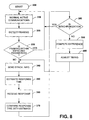
Fig. 8 illustrates a methodology for implementing handover in accordance
with an aspect of the present invention. The methodology can be implemented as
software, hardware, or a combination of both, such as at a terminal or CPE in a wireless
communications network. The methodology begins at 300, such as in connection with
the terminal system being connected and authenticated for active communications in
the wireless network, as is known in the art. Once resources have been allocated and
acquired, such as can include assigning and synchronizing transmissions from the
terminal in an assigned time slot, the methodology proceeds to 310.
-
At 310, normal active communications continue. This can include bi-directional
communications over one or more channels, time slots or frequencies
depending on the communications protocol being utilized. Part of the normal active
communications (310), can also include maintenance synchronization in which a timing
burst that contains synchronization information is transmitted periodically or
intermittently to an associated base station in the communications network. The
network provides a network response to the timing burst, which response can contain a
timing adjustment, such as to retard or advance timing for the terminal system. Thus,
the terminal can utilize the network response to adjust its framing appropriately at 320.
-
At 330, a determination is made as to whether framing is within expected
normal operating parameters. if this determination is positive, the methodology returns
to 310 to continue normal active network communications. If the determination is
negative, the methodology proceeds to 340. The determination at 330 can be made
based on the amount of framing adjustment indicated in network response or based on
a frame ID different from that expected in a received time slot or in response to a
network message broadcast to a plurality of terminals that are to be handed over for
communications with a new platform in the network.
-
At 340, which can correspond to entering a handover mode,
synchronization information is sent. The synchronization information, for example, can
include a timing burst that requests a network response. At 350, a network response
time is estimated. The estimate can be based on prior response times with the pre-handover
station or be computed based on position information, for example. An
internal clock, which is synchronized with the network, can provide a timing basis for
estimating the time when to expect receipt of a time slot from the pre-handover station
12.
-
When a terminal receives a response from the post-handover base station
14, the terminal compares the expected time with the actual received time and, based
on the comparison, adjusts frame timing for the terminal. For example, each terminal
can be programmed to compute a difference between the expected frame timing from
the pre-handover station 12 and the actual frame timing from the post-handover station
14. The difference corresponds to a timing adjustment that will enable the terminals 18-20
to synchronize with the post-handover station 14.
-
At 360, a response is received such as from the post-handover station to
which communication is being handed over. At 370, the time the response is received
is compared with the response time estimated at 350. At 380, a determination is made
as to whether, based on the comparison at 370, the terminal system is adequately
synchronized with the network. If the system is synchronized with the network, the
methodology can return to 330 in which normal active communications can be resumed.
In the event that the terminal and the network are not adequately synchronized, the
methodology proceeds to 390.
-
At 390, a time difference between the actual response time and the
estimated response time is computed. The results of the computation at 390
correspond to a timing adjustment for the terminal. At 400, the frame timing for a
transmission in the terminal are adjusted based on the computation at 390. Additionally
or alternatively, a finer level of framing adjustment can be implemented, such as based
on link layer synchronization information in a network response received from the post-handover
platform. The synchronization information, for example, can indicate in which
direction timing should be adjusted, such as to advance or retard timing. In certain
implementations, the synchronization information can also indicate an amount (e.g., in
microseconds or milliseconds) by which the terminal is to advance or retard its frame
timing.
-
From 400, the methodology then returns to 340 to repeat the foregoing
steps for finer, more precise synchronization to enable post-handover communications.
It will be understood and appreciated that the methodology can be repeated several
times so that link layer synchronization can be utilized to synchronize the terminal
adequately with the network.
-
What has been described above includes exemplary implementations of
the present invention. It is, of course, not possible to describe every conceivable
combination of components or methodologies for purposes of describing the present
invention, but one of ordinary skill in the art will recognize that many further
combinations and permutations of the present invention are possible. Accordingly, the
present invention is intended to embrace all such alterations, modifications and
variations that fall within the spirit and scope of the appended claims.