EP1430846B1 - Knochenschraube für die Wirbelsäulen- oder Knochenchirurgie - Google Patents
Knochenschraube für die Wirbelsäulen- oder Knochenchirurgie Download PDFInfo
- Publication number
- EP1430846B1 EP1430846B1 EP03026054A EP03026054A EP1430846B1 EP 1430846 B1 EP1430846 B1 EP 1430846B1 EP 03026054 A EP03026054 A EP 03026054A EP 03026054 A EP03026054 A EP 03026054A EP 1430846 B1 EP1430846 B1 EP 1430846B1
- Authority
- EP
- European Patent Office
- Prior art keywords
- bone
- thread
- head
- bone screw
- screw according
- Prior art date
- Legal status (The legal status is an assumption and is not a legal conclusion. Google has not performed a legal analysis and makes no representation as to the accuracy of the status listed.)
- Expired - Lifetime
Links
- 210000000988 bone and bone Anatomy 0.000 title claims description 82
- 238000012829 orthopaedic surgery Methods 0.000 title 1
- 238000001356 surgical procedure Methods 0.000 claims description 2
- 239000007943 implant Substances 0.000 description 27
- 230000004048 modification Effects 0.000 description 9
- 238000012986 modification Methods 0.000 description 9
- 239000000463 material Substances 0.000 description 7
- 230000000694 effects Effects 0.000 description 3
- 238000003801 milling Methods 0.000 description 3
- 239000013543 active substance Substances 0.000 description 2
- 230000004927 fusion Effects 0.000 description 2
- 238000010079 rubber tapping Methods 0.000 description 2
- 208000010392 Bone Fractures Diseases 0.000 description 1
- 229910001200 Ferrotitanium Inorganic materials 0.000 description 1
- 208000001132 Osteoporosis Diseases 0.000 description 1
- RTAQQCXQSZGOHL-UHFFFAOYSA-N Titanium Chemical compound [Ti] RTAQQCXQSZGOHL-UHFFFAOYSA-N 0.000 description 1
- 239000004480 active ingredient Substances 0.000 description 1
- 239000000560 biocompatible material Substances 0.000 description 1
- 230000015572 biosynthetic process Effects 0.000 description 1
- 239000002639 bone cement Substances 0.000 description 1
- 238000011161 development Methods 0.000 description 1
- 230000018109 developmental process Effects 0.000 description 1
- 239000003814 drug Substances 0.000 description 1
- 229940079593 drug Drugs 0.000 description 1
- 238000002347 injection Methods 0.000 description 1
- 239000007924 injection Substances 0.000 description 1
- 210000004197 pelvis Anatomy 0.000 description 1
- 229910001220 stainless steel Inorganic materials 0.000 description 1
- 239000010935 stainless steel Substances 0.000 description 1
- 230000003746 surface roughness Effects 0.000 description 1
- 239000010936 titanium Substances 0.000 description 1
Images


Classifications
-
- A—HUMAN NECESSITIES
- A61—MEDICAL OR VETERINARY SCIENCE; HYGIENE
- A61B—DIAGNOSIS; SURGERY; IDENTIFICATION
- A61B17/00—Surgical instruments, devices or methods, e.g. tourniquets
- A61B17/56—Surgical instruments or methods for treatment of bones or joints; Devices specially adapted therefor
- A61B17/58—Surgical instruments or methods for treatment of bones or joints; Devices specially adapted therefor for osteosynthesis, e.g. bone plates, screws, setting implements or the like
- A61B17/68—Internal fixation devices, including fasteners and spinal fixators, even if a part thereof projects from the skin
- A61B17/70—Spinal positioners or stabilisers ; Bone stabilisers comprising fluid filler in an implant
- A61B17/7001—Screws or hooks combined with longitudinal elements which do not contact vertebrae
-
- A—HUMAN NECESSITIES
- A61—MEDICAL OR VETERINARY SCIENCE; HYGIENE
- A61F—FILTERS IMPLANTABLE INTO BLOOD VESSELS; PROSTHESES; DEVICES PROVIDING PATENCY TO, OR PREVENTING COLLAPSING OF, TUBULAR STRUCTURES OF THE BODY, e.g. STENTS; ORTHOPAEDIC, NURSING OR CONTRACEPTIVE DEVICES; FOMENTATION; TREATMENT OR PROTECTION OF EYES OR EARS; BANDAGES, DRESSINGS OR ABSORBENT PADS; FIRST-AID KITS
- A61F2/00—Filters implantable into blood vessels; Prostheses, i.e. artificial substitutes or replacements for parts of the body; Appliances for connecting them with the body; Devices providing patency to, or preventing collapsing of, tubular structures of the body, e.g. stents
- A61F2/02—Prostheses implantable into the body
- A61F2/30—Joints
- A61F2/44—Joints for the spine, e.g. vertebrae, spinal discs
-
- A—HUMAN NECESSITIES
- A61—MEDICAL OR VETERINARY SCIENCE; HYGIENE
- A61B—DIAGNOSIS; SURGERY; IDENTIFICATION
- A61B17/00—Surgical instruments, devices or methods, e.g. tourniquets
- A61B17/56—Surgical instruments or methods for treatment of bones or joints; Devices specially adapted therefor
- A61B17/58—Surgical instruments or methods for treatment of bones or joints; Devices specially adapted therefor for osteosynthesis, e.g. bone plates, screws, setting implements or the like
- A61B17/68—Internal fixation devices, including fasteners and spinal fixators, even if a part thereof projects from the skin
- A61B17/84—Fasteners therefor or fasteners being internal fixation devices
- A61B17/86—Pins or screws or threaded wires; nuts therefor
- A61B17/864—Pins or screws or threaded wires; nuts therefor hollow, e.g. with socket or cannulated
-
- A—HUMAN NECESSITIES
- A61—MEDICAL OR VETERINARY SCIENCE; HYGIENE
- A61B—DIAGNOSIS; SURGERY; IDENTIFICATION
- A61B17/00—Surgical instruments, devices or methods, e.g. tourniquets
- A61B17/56—Surgical instruments or methods for treatment of bones or joints; Devices specially adapted therefor
- A61B17/58—Surgical instruments or methods for treatment of bones or joints; Devices specially adapted therefor for osteosynthesis, e.g. bone plates, screws, setting implements or the like
- A61B17/68—Internal fixation devices, including fasteners and spinal fixators, even if a part thereof projects from the skin
- A61B17/84—Fasteners therefor or fasteners being internal fixation devices
- A61B17/86—Pins or screws or threaded wires; nuts therefor
- A61B17/8685—Pins or screws or threaded wires; nuts therefor comprising multiple separate parts
-
- A—HUMAN NECESSITIES
- A61—MEDICAL OR VETERINARY SCIENCE; HYGIENE
- A61B—DIAGNOSIS; SURGERY; IDENTIFICATION
- A61B17/00—Surgical instruments, devices or methods, e.g. tourniquets
- A61B17/56—Surgical instruments or methods for treatment of bones or joints; Devices specially adapted therefor
- A61B17/58—Surgical instruments or methods for treatment of bones or joints; Devices specially adapted therefor for osteosynthesis, e.g. bone plates, screws, setting implements or the like
- A61B17/68—Internal fixation devices, including fasteners and spinal fixators, even if a part thereof projects from the skin
- A61B17/70—Spinal positioners or stabilisers ; Bone stabilisers comprising fluid filler in an implant
- A61B17/7001—Screws or hooks combined with longitudinal elements which do not contact vertebrae
- A61B17/7032—Screws or hooks with U-shaped head or back through which longitudinal rods pass
-
- A—HUMAN NECESSITIES
- A61—MEDICAL OR VETERINARY SCIENCE; HYGIENE
- A61B—DIAGNOSIS; SURGERY; IDENTIFICATION
- A61B17/00—Surgical instruments, devices or methods, e.g. tourniquets
- A61B17/56—Surgical instruments or methods for treatment of bones or joints; Devices specially adapted therefor
- A61B17/58—Surgical instruments or methods for treatment of bones or joints; Devices specially adapted therefor for osteosynthesis, e.g. bone plates, screws, setting implements or the like
- A61B17/68—Internal fixation devices, including fasteners and spinal fixators, even if a part thereof projects from the skin
- A61B17/70—Spinal positioners or stabilisers ; Bone stabilisers comprising fluid filler in an implant
- A61B17/7001—Screws or hooks combined with longitudinal elements which do not contact vertebrae
- A61B17/7035—Screws or hooks, wherein a rod-clamping part and a bone-anchoring part can pivot relative to each other
- A61B17/7037—Screws or hooks, wherein a rod-clamping part and a bone-anchoring part can pivot relative to each other wherein pivoting is blocked when the rod is clamped
-
- A—HUMAN NECESSITIES
- A61—MEDICAL OR VETERINARY SCIENCE; HYGIENE
- A61B—DIAGNOSIS; SURGERY; IDENTIFICATION
- A61B17/00—Surgical instruments, devices or methods, e.g. tourniquets
- A61B17/56—Surgical instruments or methods for treatment of bones or joints; Devices specially adapted therefor
- A61B17/58—Surgical instruments or methods for treatment of bones or joints; Devices specially adapted therefor for osteosynthesis, e.g. bone plates, screws, setting implements or the like
- A61B17/68—Internal fixation devices, including fasteners and spinal fixators, even if a part thereof projects from the skin
- A61B17/70—Spinal positioners or stabilisers ; Bone stabilisers comprising fluid filler in an implant
- A61B17/7001—Screws or hooks combined with longitudinal elements which do not contact vertebrae
- A61B17/7041—Screws or hooks combined with longitudinal elements which do not contact vertebrae with single longitudinal rod offset laterally from single row of screws or hooks
Definitions
- the invention relates to a bone screw for spinal or bone surgery and an implant with such a bone screw.
- a bone screw according to the preamble of patent claim 1 and an implant with such a bone screw is known from WO 02/38054.
- the known bone screw it is possible to firmly connect parts of the bone in a bone fracture by the bone screw acts as a tension element and at the same time as a fusion element, wherein the recesses in the wall allow the ingrowth of bone material or vessels.
- the helical tips of the bone thread are interrupted at the points at which recesses are formed in the wall.
- teeth are formed, which have a milling effect when screwing into the bone and can damage the bone.
- the use of the known bone screw can lead to problems when screwing.
- a bone screw which has a shaft with a bone thread, a tip and a head, which are integrally formed with each other.
- the bone screw also has a through the Head and shaft extending coaxial blind hole bore, from which extend a plurality of radial bores through the screw wall therethrough.
- the radial bores are each arranged between the thread flanks of the bone thread.
- the holes serve as a channel for the injection and distribution of bone cement. An ingrowth of bone material or vessels into the holes is therefore not possible.
- a screw connection for a bone joint which includes a sleeve which allows at the end of an internal thread for screwing a closure member.
- the sleeve has a bone thread with gaps that open into the interior of the sleeve.
- a hollow implant which is cylindrical, with a substantially closed end and an internal thread at the other end into which a closure cap can be screwed.
- the implant has a bone thread on the outside and a plurality of recesses in the bone thread portion.
- a first embodiment of the element 1 of the bone screw according to the invention is formed from a cylindrical tube 2 having a first end 3 and a second end 4 opposite thereto.
- the tube 2 has on its outer wall a bone threaded portion 5 with a bone thread for screwing into a bone.
- the bone thread is formed as a self-tapping thread and has in a known manner thread flanks 6, a spiral tip 7, a thread base 8 with a width B and a pitch P.
- the wall of the element 1 has a plurality of recesses 9 with a circular cross-section on.
- the recesses 9 are arranged so that their center lies in the thread root 8 and the diameter of each recess 9 is smaller than the thread pitch P and in particular not greater than the width B of the thread base, so that in the in Figs. 1 and 2 illustrated embodiment, the recesses 9 are completely in the thread base 8 and do not extend into the flanks 6.
- a plurality of on the helix evenly spaced recesses 9 are provided, so that seen in the axial direction in each case are the recesses of a thread over the recesses of the underlying thread.
- the length of the tube 2 corresponds to the shaft length of a bone screw to be used for the respective application.
- the element consists of a biocompatible material, eg. As titanium or stainless steel.
- the modified embodiment shown in Fig. 3 differs from the embodiment shown in Figures 1 and 2 in that the diameter D 'of the recess 9' is greater than the width of the thread root 8, so that the recesses 9 'in the Traverse flanks 6 of the bone thread, but without breaking the spiral tip 7. This makes it possible to make the recesses larger in order to achieve a better fusion effect with the bone, but the formation of teeth with a milling action when screwing is prevented because the cutting tip of the thread remains intact.
- the recesses are oval or diamond-shaped. It is crucial that they are arranged in the thread root and are dimensioned so that the cutting tip of the bone thread is not injured. In a further modification recesses are not provided in each thread.
- the bone thread section 5 extends over the entire length of the tube 2.
- the internal thread 11 may also extend over the entire length.
- the internal thread 11 may also be provided only at one end in a section or not at all. The connection with the other implant parts takes place in the event that no internal thread is provided, e.g. over snug fit.
- the tubular element 1 is in each case a component of the implant.
- the tubular element is connectable at its second end 4 in one embodiment to a point 12 comprising the actual tip portion and a shaft 13 having an external thread cooperating with the internal thread 11 of the tubular element.
- the tip 12 has a coaxial through bore 15 which has a channel for introducing active ingredients to the position at which the implant is to be anchored forms.
- the tip is formed as a self-tapping tip 15 with or without a continuous coaxial bore.
- the implant is designed as a bone screw with a head 16 which has the actual head part 17 with a slot or a hexagon socket and a threaded shaft 18 with an external thread which cooperates with the internal thread 11 of the tubular element 1.
- a tubular element of suitable length is selected or shortened a correspondingly formed tube to the appropriate length. Then the tip is screwed tightly to the tubular element 1. Then either the head is screwed on and the bone screw is screwed into the bone. In this case, the cavity formed by the tubular element serves for ingrowth of bone material or vessels through the recesses 9 and 9 ', respectively.
- either bone material or an active substance is introduced into the tubular element 1 and the head is screwed on. Then the bone screw is screwed into the bone together with the introduced material.
- a threaded member 19 shown in Fig. 4 which has a first portion 20 with a with the Internal thread 11 cooperating external thread for screwing into the tubular element 1, a stop in the form of a shoulder 21 and an adjacent thereto grip portion 22 with external hexagon 23 has.
- the handle portion 22 may be formed with or without external thread and its length is dimensioned so that the tubular element 1 can be positioned with screwed-on tip at a desired location in the bone.
- the threaded member 19 has a continuous coaxial channel.
- the threaded member 19 is screwed onto the tubular element 1 and this sunk by means of the threaded element together with the tip in the bone. Subsequently, the threaded element is unscrewed again.
- the implant consists of a screw member which is formed by the tubular member 1 with screwed-on tip 12, 12 'or 15, as described above, and from a with the screw member mono-axially connectable receiving part 24 for receiving a rod 100 provided for connecting a plurality of such implants.
- the receiving part 24 is formed substantially cylindrical and has a recess 25 with a U-shaped cross section, which is just sized so large that the rod 100 is inserted and fits into the bottom of the recess.
- two free legs 26, 27 are formed. Adjacent to the free end, the legs 26, 27 on an internal thread 28, which cooperates with a corresponding external thread of a screwed between the legs of the inner screw 29 for fixing the rod 100.
- the receiving part 24 has a threaded shank 30 for screwing into the tubular element 1.
- the implant is first fully assembled, with the tubular member filled with drugs or bone material when required. Subsequently, the implant is screwed into the bone. Then, the connection via the rod to one or more other such implants. In the correct position, the rod is then fixed over the inner screw.
- the implant is particularly suitable for use on the spine. Due to the continuous helical tip of the bone thread of the tubular element, the vertebrae are not additionally damaged when screwing.
- implants shown in FIG. 6 are likewise implants in which a screw element formed from the tubular element 1 and the tip 12, 12 'or 15 is connected to a receiving part for receiving a rod 100.
- the connection to the rod is polyaxial.
- the receiving part 31 is formed cylindrically with a first end 32 and an opposite second end 33. Coaxially with the center shaft M is provided from the first end 32 extending from first coaxial bore 34 extending to extends to a predetermined distance from the second end 33. At the second end 33, a second bore 35 is provided, whose diameter is smaller than the diameter of the first bore and which widens to the first bore in a hollow spherical segment-shaped portion.
- the recording part 31 has starting from the first end 32 a perpendicular to the longitudinal axis extending U-shaped recess through the two free legs 36, 37 are formed. Adjacent to the first end 32, the legs have an internal thread 38. Further, an external thread 39 is provided on the outside of the legs.
- a spherical segment-shaped screw head 40 For connecting the screw member with the receiving part 31, a spherical segment-shaped screw head 40 is provided, whose ball radius is substantially equal to the radius of the hollow spherical segment-shaped portion of the receiving part 31 and which is pivotable in loose inserted state in the receiving part.
- the head 40 further has a recess 41 for engagement with a screwdriver at its flattened end to be aligned with the first end 32 of the receiving part 31.
- the screw head 40 has a cylindrical neck 42 with an outer diameter corresponding to the outer diameter of the tubular element 1. From the neck extends a shoulder 43 with an external thread with which the screw head 40 can be screwed into the tubular element.
- a pressure element 44 is provided, which is cylindrical, so that it is displaceable in the receiving part and which at one end a spherical recess for receiving a portion of the screw head and Having its opposite end a U-shaped recess for receiving the rod.
- the pressure element 44 further has a coaxial bore so that the screw element can be screwed in when the pressure element is inserted.
- the screw element consisting of tip 12, optionally filled with bone material or an active substance, and screw head 40 is first assembled. Subsequently, the screw element and the pressure element are inserted into the receiving part and the screw element is screwed into the bone or the vertebra. The connection with other implants over the rod is done in a known manner.
- the head and rod fixation is not limited to that described, but any head and rod fixation of known polyaxial screws can be used.
- the polyaxial connection with the rod 100 is not in the direction of the screw axis, as in the example of FIG. 6a), but offset laterally to the screw axis.
- the implant according to FIG. 6b) comprises a screw element consisting of the tubular element 1, the tip 12 and the spherical segment-shaped head 40 shown in FIG. 6a) and a two-part frame 47 receiving the head 40 with a lower part 48 and facing the tubular element 1 an upper part 49 facing away from the tubular element 1, which together comprise the rod 100.
- the upper part 49 and the lower part 48 are identical and arranged in mirror image to each other. They have a central bore 50, 51, which is provided with an internal thread and on the each other part 48, 49 facing away from the surface has a counterbore.
- the side of the bore 50, 51 is provided at a distance from this one to the other part 48, 49 out of the cylinder segment shaped recess 52, 53 for holding the rod.
- Lower part 48 and upper part 49 of the socket are connected to each other by a screw 58, which is insertable into the internal thread of the upper part, and in the internal thread of the lower part can be screwed.
- the screw 58 In its guided through the upper part 49, the screw 58 has a diameter which is smaller than the diameter of the inner thread of the upper part and has in its guided through the lower part a part cooperating with the inner thread of the lower part of external thread.
- the cylinder-segment-shaped recesses 52, 53 and the spherical segment-shaped recesses 54, 55 are dimensioned and arranged relative to each other, that in the state in which the rod and the head are held, the lower part 48 and the upper part 49 are aligned parallel to each other and spaced from each other have.
- the implant is particularly suitable for the fixation of fractures on the pelvis and long bones.
- the embodiment shown in Fig. 6c) differs from the embodiment shown in Fig. 6b), characterized in that the socket 47 'for detecting two rods 100, 100' has a symmetrically formed in the lower part 48 'and upper part 49'.
- the lower part 48 'and the upper part 49' thereby formed symmetrical to a plane defined by the center line of the rods 100, 100 'and the center of the spherical segment-shaped head 40 of the screw and each have two holes 50, 50', 51, 51 ', two Cylinder-shaped recesses 52, 52 'and 53, 53' on.
- two fixing screws 58, 58 ' are provided for fixing two fixing screws 58, 58 'are provided.
- the operation is analogous to the previously described embodiment, except that two rods are to be fixed.
- the tubular member 101 is not generally cylindrical in shape, but has a central conical bone thread portion 102 which tapers towards the tip end 103 of the member. Adjacent to the conical portion extends on both sides of the conical portion to the opposite ends 103, 104 each have a cylindrical portion 105, 106 with an internal thread for connection to the tip at one end or with a head, a threaded member, or a receiving part as described above at the other end.
- the cylindrical portion 106 to be connected to the tip is not provided, but the free end of the conical bone thread portion itself acts as a tip.
Description
- Die Erfindung betrifft eine Knochenschraube für die Wirbelsäulen- oder Knochenchirurgie und ein Implantat mit einer solchen Knochenschraube.
- Eine Knochenschraube nach dem Oberbegriff des Patentanspruchs 1 und ein Implantat mit einer solchen einer Knochenschraube ist aus der WO 02/38054 bekannt. Mit der bekannten Knochenschraube ist es möglich, bei einer Knochenfraktur Teile des Knochen miteinander fest zu verbinden, indem die Knochenschraube als Zugelement und gleichzeitig als Fusionselement wirkt, wobei die Ausnehmungen in der Wandung das Einwachsen von Knochenmaterial oder Gefäßen erlauben.
- Bei der bekannten Knochenschraube sind jedoch die Wendelspitzen des Knochengewindes an den Stellen unterbrochen, an denen Ausnehmungen in der Wandung gebildet sind. Dadurch werden Zähne gebildet, die beim Einschrauben in den Knochen eine Fräswirkung haben und den Knochen beschädigen können. Insbesondere für z. B. durch Osteoporose geschwächte Knochen kann die Verwendung der bekannten Knochenschraube zu Problemen beim Einschrauben führen.
- Aus der DE 199 49 285 C2 ist eine Knochenschraube bekannt, die einen Schaft mit einem Knochengewinde, eine Spitze und einen Kopf aufweist, die einstückig miteinander ausgebildet sind. Die Knochenschraube weist ferner eine sich durch den Kopf und den Schaft erstreckende koaxiale Sacklochbohrung auf, von der aus sich eine Mehrzahl von radialen Bohrungen durch die Schraubenwand hindurch erstrecken. Die radialen Bohrungen sind jeweils zwischen den Gewindeflanken des Knochengewindes angeordnet. Die Bohrungen dienen als Kanal für die Einspritzung und Verteilung von Knochenzement. Ein Einwachsen von Knochenmaterial oder Gefäßen in die Bohrungen ist daher nicht möglich.
- Aus der DE 195 40 180 A1 ist eine Schraubverbindung für ein Knochengelenk bekannt, die eine Hülse beinhaltet, welche am Ende ein Innengewinde zum Einschrauben eines Verschlußteiles erlaubt. Die Hülse weist ein Knochengewinde auf mit Zwischenräumen, die ins Innere der Hülse einmünden.
- Aus der WO 98/35636 ist ein hohles Implantat bekannt, welches zylindrisch ausgebildet ist, mit einem im wesentlichen geschlossenen Ende und einem Innengewinde am anderen Ende, in das eine Verschlußkappe eingeschraubt werden kann. Das Implantat hat ein Knochengewinde an der Außenseite und eine Mehrzahl von Ausnehmungen in dem Knochengewindeabschnitt.
- Es ist Aufgabe der Erfindung, eine verbesserte Knochenschraube der eingangs beschriebenen Art und ein dieses verwendendes Implantat bereitzustellen, das vielseitig einsetzbar ist.
- Die Aufgabe wird gelöst durch eine Knochenschraube nach Anspruch 1 bzw. durch ein Implantat nach Anspruch 8. Weiterbildungen der Erfindung sind in den Unteransprüchen angegeben.
- Weitere Merkmale und Zweckmäßigkeiten der Erfindung ergeben sich aus der Beschreibung von Ausführungsbeispielen anhand der Figuren. Von den Figuren zeigen:
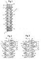
- Fig. 1:
- eine Seitenansicht einer ersten Ausführungsform der Erfindung des rohrförmigen Elements der Knochenschraube ;
- Fig. 2:
- eine vergrößerte teilgeschnittene Darstellung des rohrförmigen Elements von Fig. 1;
- Fig. 3:
- eine vergrößerte teilgeschnittene Darstellung einer Abwandlung des rohrförmigen Elements von Fig. 1; und
- Aus der US 6,391,058 B1 ist ein Zwischenwirkel implantat bekannt, welches einen hohlen zylindrisch Körper mit einem Auβengeweinde beinhaltet, wobei Öffnungen in der der Wandung vorgesehen sind. In einer Ausführungsform sind die Öffnungen so angeordnet, daβ das Gewinde nicht durchbrochen wird.
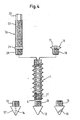
- Fig. 4:
- Ausführungsbeispiele von Implantaten unter Verwendung des rohrförmigen Elements von Fig. 1;
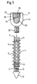
- Fig. 5:
- weitere Ausführungsbeispiele von Implantaten unter Verwendung des rohrförmigen Elements von Fig. 1;
- Fig. 6a) bis c):
- weitere Ausführungsbeispiele von Implantaten unter Verwendung des rohrförmigen Elements von Fig. 1
- Fig. 7:
- eine zweite Ausführungsform des rohrförmigen Elements.
- Wie am besten aus Fig. 1 und 2 ersichtlich ist, ist eine erste Ausführungsform des Elements 1 der erfindungsgemäßen Knochenschraube aus einem zylindrischen Rohr 2 mit einem ersten Ende 3 und einem diesem gegenüberliegenden zweiten Ende 4 ausgebildet. Das Rohr 2 weist an seiner Außenwand einen Knochengewindeabschnitt 5 mit einem Knochengewinde zum Einschrauben in einen Knochen auf. Das Knochengewinde ist als selbstschneidendes Gewinde ausgebildet und hat in bekannter Weise Gewindeflanken 6, eine Wendelspitze 7, einen Gewindegrund 8 mit einer Breite B und eine Gewindesteigung P. In wenigstens dem Knochengewindeabschnitt 5 weist die Wandung des Elements 1 eine Mehrzahl von Ausnehmungen 9 mit kreisförmigem Querschnitt auf. Die Ausnehmungen 9 sind so angeordnet, daß ihre Mitte jeweils im Gewindegrund 8 liegt und der Durchmesser einer jeden Ausnehmung 9 ist kleiner, als die Gewindesteigung P und insbesondere nicht größer als die Breite B des Gewindegrunds, so daß in dem in Fig. 1 und 2 dargestellten Ausführungsbeispiel die Ausnehmungen 9 vollständig im Gewindegrund 8 liegen und sich nicht in die Flanken 6 erstrecken. Es sind in jedem Gewindegang im Gewindegrund 8 eine Mehrzahl von auf der Schraubenlinie gleichmäßig beabstandeten Ausnehmungen 9 vorgesehen, so daß sich in axialer Richtung gesehen jeweils die Ausnehmungen eines Gewindegangs über den Ausnehmungen des darunterliegenden Gewindegangs befinden.
- Wie insbesondere aus Fig. 1 ersichtlich ist, weist das Element 1 angrenzend an das erste Ende einen knochengewindefreien Abschnitt 10 mit einer glatten Außenwand auf, in der keine Ausnehmungen gebildet sind. Ferner ist bei dem gezeigten Ausführungsbeispiel angrenzend an das erste Ende 3 und angrenzend an das zweite Ende 4 des Rohrs ein Innengewindeabschnitt 11 gebildet, der zum Verbinden mit später beschriebenen Elementen eines Implantats dient.
- Die Länge des Rohres 2 entspricht der Schaftlänge einer für die jeweilige Anwendung zu verwendenden Knochenschraube. Das Element besteht aus einem körperverträglichen Material, z. B. Titan oder Edelstahl.
- Die in Fig. 3 gezeigte abgewandelte Ausführungsform unterscheidet sich von der in den Figuren 1 und 2 dargestellten Ausführungsform dadurch, daß der Durchmesser D' der Ausnehmung 9' größer ist, als die Breite des Gewindegrunds 8, so daß sich die Ausnehmungen 9' in die Flanken 6 des Knochengewindes hineinerstrecken, ohne jedoch die Wendelspitze 7 zu durchbrechen. Dadurch ist es möglich, die Ausnehmungen größer zu bilden, um eine bessere Fusionswirkung mit dem Knochen zu erzielen, eine Entstehung von Zähnen mit Fräswirkung beim Einschrauben wird jedoch verhindert, da die Schneidspitze des Gewindes unversehrt bleibt.
- In einer nicht dargestellten Abwandlung der in den Figuren 1 und 2 gezeigten Ausführungsformen sind alle oder ein Teil der Ausnehmungen 9, 9' an der Außenseite der Wandung mit einer Ansenkung versehen, die eine Oberflächenrauhigkeit bildet, welche ein Ein- bzw. Anwachsen erleichtert. Der Durchmesser dieser Ansenkung in Schraubenachsrichtung ist jedoch kleiner als die Gewindesteigung P, so daß die Wendelspitze 7 unversehrt ist.
- In einer weiteren Abwandlung sind die Ausnehmungen oval oder rautenförmig. Entscheidend ist, daß sie im Gewindegrund derart angeordnet sind und so bemessen sind, daß die Schneidspitze des Knochengewindes nicht verletzt wird. In einer weiteren Abwandlung sind nicht in jedem Gewindegang Ausnehmungen vorgesehen.
- In einer weiteren Abwandlung erstreckt sich der Knochengewindeabschnitt 5 über die gesamte Länge des Rohrs 2. Das Innengewinde 11 kann sich ebenfalls über die gesamte Länge erstrecken. Alternativ kann das Innengewinde 11 auch nur an einem Ende in einem Abschnitt oder gar nicht vorgesehen sein. Die Verbindung mit den weiteren Implantatteilen erfolgt im Fall, daß kein Innengewinde vorgesehen ist, z.B. über Paßsitz.
- In den in den Figuren 4 bis 6 gezeigten erfindungsgemäßen Ausführungsbeispielen für Implantate ist das rohrförmige Element 1 jeweils ein Bestandteil des Implantats. Das rohrförmige Element ist an seinem zweiten Ende 4 in einer Ausführungsform mit einer Spitze 12 verbindbar, die den eigentlichen Spitzenteil und einen Schaft 13 umfaßt, der ein mit dem Innengewinde 11 des rohrförmigen Elements zusammenwirkendes Außengewinde aufweist. In einer Abwandlung weist die Spitze 12' eine koaxiale durchgehende Bohrung 15 auf, die einen Kanal zum Einbringen von Wirkstoffen an die Position, an der das Implantat verankert werden soll, bildet. In einer weiteren Abwandlung ist die Spitze als selbstschneidende Spitze 15 mit oder ohne durchgehende koaxiale Bohrung ausgebildet.
- In einem ersten Ausführungsbeispiel ist das Implantat als Knochenschraube mit einem Kopf 16 ausgebildet, der den eigentlichen Kopfteil 17 mit einem Schlitz oder einem Innensechskant und einen Gewindeschaft 18 mit einem Außengewinde, das mit dem Innengewinde 11 des rohrförmigen Elements 1 zusammenwirkt, aufweist.
- Im Betrieb wird ein rohrförmiges Element passender Länge ausgewählt oder ein entsprechend ausgebildetes Rohr auf die passende Länge gekürzt. Dann wird die Spitze mit dem rohrförmigen Element 1 fest verschraubt. Anschließend wird entweder gleich der Kopf aufgeschraubt und die Knochenschraube in den Knochen eingeschraubt. In diesem Fall dient der durch das rohrförmige Element gebildete Hohlraum zum Einwachsen von Knochenmaterial oder Gefäßen durch die Ausnehmungen 9 bzw. 9'. Alternativ wird entweder Knochenmaterial oder ein Wirkstoff in das rohrförmige Element 1 eingebracht und der Kopf aufgeschraubt. Dann wird die Knochenschraube zusammen mit dem eingebrachten Material in den Knochen eingeschraubt.
- Aufgrund der Tatsache, daß die Wendelspitze des Knochengewindes nicht durch die Ausnehmungen unterbrochen ist, sondern unversehrt ist, erfolgt ein weiches Einschrauben ohne Fräseffekt, wodurch eine über das Einschrauben hinausgehende Beschädigung des Knochens nicht auftritt.
- Als Instrument zum Einschrauben des rohrförmigen Elements 1 in den Knochen ist ein in Fig. 4 gezeigtes Gewindeelement 19 vorgesehen, das einen ersten Abschnitt 20 mit einem mit dem Innengewinde 11 zusammenwirkendes Außengewinde zum Einschrauben in das rohrförmige Element 1, einen Anschlag in Form einer Schulter 21 und einen daran angrenzenden Griffabschnitt 22 mit Außensechskant 23 aufweist. Der Griffabschnitt 22 kann mit oder ohne Außengewinde ausgebildet sein und seine Länge ist so bemessen, daß das rohrförmige Element 1 mit aufgeschraubter Spitze an einer gewünschten Stelle im Knochen positionierbar ist. In einer nicht dargestellten Abwandlung weist das Gewindeelement 19 einen durchgehenden koaxialen Kanal auf.
- Im Betrieb wird das Gewindeelement 19 auf das rohrförmige Element 1 aufgeschraubt und dieses mittels des Gewindelements samt Spitze im Knochen versenkt. Anschließend wird das Gewindeelement wieder herausgeschraubt.
- Bei dem in Fig. 5 gezeigten Ausführungsbeispiel besteht das Implantat aus einem Schraubenelement, das durch das rohrförmige Element 1 mit aufgeschraubter Spitze 12, 12' oder 15, wie zuvor beschrieben, gebildet ist, und aus einem mit dem Schraubenelement monoaxial verbindbaren Aufnahmeteil 24 zum Aufnehmen eines Stabs 100, der zum Verbinden mehrerer derartiger Implantate vorgesehen ist. Das Aufnahmeteil 24 ist im wesentlichen zylindrisch ausgebildet und weist eine Ausnehmung 25 mit U-förmigem Querschnitt auf, die gerade so groß bemessen ist, daß der Stab 100 einlegbar ist und in den Grund der Ausnehmung passt. Durch die U-förmige Ausnehmung 25 sind zwei freie Schenkel 26, 27 gebildet. Angrenzend an das freie Ende weisen die Schenkel 26, 27 ein Innengewinde 28 auf, welches mit einem entsprechenden Außengewinde einer zwischen die Schenkel einzuschraubenden Innenschraube 29 zum Fixieren des Stabs 100 zusammenwirkt. An seinem dem freien Ende abgewandten Ende weist das Aufnahmeteil 24 einen Gewindeschaft 30 zum Einschrauben in das rohrförmige Element 1 auf.
- Im Betrieb wird vorzugsweise das Implantat zuerst vollständig zusammengesetzt, wobei das rohrförmige Element wenn es erforderlich ist, mit Wirkstoffen oder Knochenmaterial gefüllt ist. Anschließend wird das Implantat in den Knochen eingeschraubt. Dann erfolgt die Verbindung über den Stab zu einem oder mehreren anderen derartigen Implantaten. In korrekter Position wird anschließend der Stab über die Innenschraube fixiert. Das Implantat ist besonders geeignet für die Anwendung an der Wirbelsäule. Durch die durchgehende Wendelspitze des Knochengewindes des rohrförmigen Elements werden die Wirbel beim Einschrauben nicht zusätzlich beschädigt.
- Die in Fig. 6 gezeigten weiteren Ausführungsbeispiele von Implantaten, sind ebenfalls Implantate bei denen ein aus dem rohrförmigen Element 1 und der Spitze 12, 12' oder 15 gebildetes Schraubenelement mit einem Aufnahmeteil zur Aufnahme eines Stabs 100 verbunden ist. Im Unterschied zu dem Ausführungsbeispiel nach Fig. 5 ist die Verbindung mit dem Stab jedoch polyaxial.
- In dem in Fig. 6a) gezeigten Ausführungsbeispiel ist das Aufnahmeteil 31 zylindrisch ausgebildet mit einem ersten Ende 32 und einem gegenüberliegenden zweiten Ende 33. Koaxial zur Mittenschse M ist eine sich von dem ersten Ende 32 aus erstreckende erste koaxiale Bohrung 34 vorgesehen, die sich bis zu einem vorbestimmten Abstand von dem zweiten Ende 33 hin erstreckt. An dem zweiten Ende 33 ist eine zweite Bohrung 35 vorgesehen, die deren Durchmesser kleiner als der Durchmesser der ersten Bohrung ist und die sich zur ersten Bohrung hin in einem hohlkugelsegmentförmigen Abschnitt erweitert. Das Aufnahmeteil 31 weist ausgehend von dem ersten Ende 32 eine sich senkrecht zu Längsachse erstreckende U-förmige Ausnehmung durch die zwei freie Schenkeln 36, 37 gebildet sind. Angrenzend an das erste Ende 32 weisen die Schenkel einen Innengewinde 38 auf. Ferner ist an der Außenseite der Schenkel ein Außengewinde 39 vorgesehen.
- Zum Verbinden des Schraubenelements mit dem Aufnahmeteil 31 ist ein kugelsegmentförmiger Schraubenkopf 40 vorgesehen, dessen Kugelradius im wesentlichen gleich dem Radius des hohlkugelsegmentförmigen Abschnitts des Aufnahmeteils 31 ist und der in lose eingesetztem Zustand in dem Aufnahmeteil schwenkbar ist. Der Kopf 40 weist ferner an seinem zu dem ersten Ende 32 des Aufnahmeteils 31 hin zu richtenden abgeflachten Ende eine Ausnehmung 41 zum Ineingriffbringen mit einem Schraubendreher auf. An seinem gegenüberliegenden Ende besitzt der Schraubenkopf 40 einen zylindrischen Hals 42 mit einem Außendurchmesser, der dem Außendurchmesser des rohrförmigen Elements 1 entspricht. Von dem Hals erstreckt sich ein Ansatz 43 mit einem Außengewinde mit dem der Schraubenkopf 40 in das rohrförmige Element einschraubbar ist.
- Zum Fixieren des Kopfes 40 in dem Aufnahmeteil und damit der Winkelstellung des Schraubenelements ist ein Druckelement 44 vorgesehen, welches zylindrisch ausgebildet ist, so daß es in dem Aufnahmeteil verschiebbar ist und welches an seinem einen Ende eine sphärische Ausnehmung zur Aufnahme eines Abschnitts des Schraubenkopfs und an seinem gegenüberliegenden Ende eine U-förmige Ausnehmung zur Aufnahme des Stabs aufweist. Das Druckelement 44 weist ferner eine koaxiale Bohrung auf, damit das Schraubenelement bei eingesetztem Druckelement einschraubbar ist. Zum Fixieren von Kopf 40 und Stab 100 ist eine zwischen die Schenkel 36, 37 einschraubbare Innenschraube 45 vorgesehen. Zur Sicherung der Fixierung ist eine auf das Aufnahmeteil 31 aufschraubbare Sicherungsmutter 46 vorgesehen.
- Im Betrieb wird zuerst das aus Spitze 12, gegebenenfalls mit Knochenmaterial oder einem Wirkstoff gefüllte rohrförmigem Element 1 und Schraubenkopf 40 bestehende Schraubenelement zusammengesetzt. Anschließend werden das Schraubenelement und das Druckelement in das Aufnahmeteil eingeführt und das Schraubenelement in den Knochen oder den Wirbel eingeschraubt. Die Verbindung mit anderen Implantaten über den Stab erfolgt in bekannter Weise.
- Die Kopf- und Stabfixierung ist nicht auf das beschriebene beschränkt, sondern es kann jede Kopf- und Stabfixierung bekannter Polyaxialschrauben verwendet werden.
- In dem in den Figuren 6b) und 6c) gezeigten Ausführungsbeispiel erfolgt die polyaxiale Verbindung mit dem Stab 100 nicht in Richtung der Schraubenachse, wie bei dem Beispiel gemäß Fig. 6a), sondern seitlich zur Schraubenachse versetzt.
- Das Implantat gemäß Fig. 6b) umfaßt ein aus dem rohrförmigen Element 1, der Spitze 12 und dem in Fig. 6a) gezeigten kugelsegmentförmigen Kopf 40 bestehendes Schraubenelement sowie eine dem Kopf 40 aufnehmende zweiteilige Fassung 47 mit einem dem rohrförmigen Element 1 zugewandten Unterteil 48 und einem dem rohrförmigen Element 1 abgewandten Oberteil 49, die zusammen den Stab 100 umfassen. Das Oberteil 49 und das Unterteil 48 sind identisch ausgebildet und spiegelbildlich zueinander angeordnet. Sie weisen eine zentrale Bohrung 50, 51 auf, die mit einem Innengewinde versehen ist und auf der dem jeweils anderen Teil 48, 49 abgewandten Oberfläche eine Senkbohrung aufweist. Seitlich der Bohrung 50, 51 ist in einem Abstand von dieser eine zu dem jeweils anderen Teil 48, 49 hin zylindersegmentförmig ausgebildete Ausnehmung 52, 53 zum Halten des Stabs vorgesehen. Auf der anderen Seite der Bohrung 50 weisen das Unterteil 48 und das Oberteil 49 auf der dem jeweils anderen Teil zugewandten Seite eine kugelsegmentförmige Ausnehmung 54, 55 zum Halten des Schraubenkopfs 40 auf. Auf der dem anderen Teil 48, 49 abgewandten Oberfläche schließt sich koaxial zu der Ausnehmung 54, 55 eine nach außen zunehmende Ausnehmung 56, 57 an.
- Unterteil 48 und Oberteil 49 der Fassung sind durch eine Schraube 58 miteinander verbunden, die in das Innengewinde des Oberteils einführbar ist, und in das Innengewinde des Unterteils einschraubbar ist. In ihrem durch das Oberteil 49 geführten Teil hat die Schraube 58 einen Durchmesser, der kleiner ist, als der Durchmesser des Innengewindes des Oberteils und weist in ihrem durch das Unterteil geführten Teil ein mit dem Innengewinde des Unterteils zusammenwirkendes Außengewinde auf. Die zylindersegmentförmigen Ausnehmungen 52, 53 und die kugelsegmentförmigen Ausnehmungen 54, 55 sind so dimensioniert und so zueinander angeordnet, daß in dem Zustand in dem der Stab und der Kopf gehalten sind, das Unterteil 48 und das Oberteil 49 parallel zueinander ausgerichtet sind und einen Abstand voneinander besitzen.
- Im Betrieb wird erst das Schraubenelement zusammengesetzt. Das Oberteil und das Unterteil der Fassung sind durch Losedrehen der Schraube 58 um 90 Grad gegeneinander verdreht, so daß das Schraubenelement in das Unterteil 48 einführbar ist. Das Schraubenelement wird eingeführt, bis sein Kopf 40 in der kugelsegmentförmigen Ausnehmung 54 anliegt. Anschließend wird es in den Knochen eingeschraubt. Dann wird der Stab 100 aufgenommen und das Oberteil 49 um 90 Grad zum Fassen des Stabs gedreht. Nach erfolgter Justierung der Winkelstellung des Schraubenkopfs 40 in der Fassung und der nPosition des Stabs erfolgt ein Fixieren durch Festziehen der Schraube 58.
- Das Implantat ist insbesondere für die Fixierung von Frakturen am Becken und an Röhrenknochen geeignet.
- Das in Fig. 6c) dargestellte Ausführungsbeispiel unterscheidet sich von dem in Fig. 6b) dargestellten Ausführungsbeispiel dadurch, daß die Fassung 47' zum Erfassen von zwei Stäben 100, 100' ein in sich symmetrisch ausgebildetes Unterteil 48' und Oberteil 49' aufweist. Das Unterteil 48' und das Oberteil 49' dabei symmetrisch zu einer durch die Mittellinie der Stäbe 100, 100' und den Mittelpunkt des kugelsegmentförmigen Kopfs 40 der Schraube definierten Ebene ausgebildet und weisen jeweils zwei Bohrungen 50, 50', 51, 51', zwei zylindersegmentförmige Ausnehmungen 52, 52' bzw. 53, 53' auf. Zum Fixieren sind zwei Fixierschrauben 58, 58' vorgesehen. Der Betrieb ist analog zu dem vorherbeschriebenen Ausführungsbeispiel, nur daß zwei Stäbe zu fixieren sind.
- In einer in Fig. 7 gezeigten zweiten Ausführungsform ist das rohrförmige Element 101 nicht insgesamt zylindrisch ausgebildet, sondern weist einen mittleren konischen Knochengewindeabschnitt 102 auf, der sich in Richtung zu dem mit der Spitze zu verbindenden Ende 103 des Elements verjüngt. Angrenzend an den konischen Abschnitt erstreckt sich beidseitig des konischen Abschnitts bis zu den einander gegenüberliegenden Enden 103, 104 jeweils ein zylindrischer Abschnitt 105, 106 mit einem Innengewinde zum Verbinden mit der Spitze an einem Ende bzw. mit einem Kopf, einem Gewindeelement, oder einem Aufnahmeteil wie zuvor beschrieben am anderen Ende.
- In einer Abwandlung ist der mit der Spitze zu verbindende zylindrische Abschnitt 106 nicht vorgesehen, sondern das freie Ende des konischen Knochengewindeabschnitts wirkt selbst als Spitze.
Claims (13)
- Knochenschraube mit einem rohrförmigen Element für die Wirbelsäulen- oderKnochenchirurgie mit einem Knochengewindeabschnitt (5; 102) mit einem Knochengewinde und mit einer Mehrzahl von Ausnehmungen (9, 9') in dem Knochengewindeabschnitt (5; 102), wobei wenigstens ein Ende des Elements (1; 101) zur Aufnahme eines Kopfes bzw. einer Spitze ausgebildet ist, wobei eine an einem Ende mit dem rohrförmigen Element (1; 101) lösbar verbundene Spitze (12, 12', 15) vorgesehen ist, dadurch gekennzeichnet daβ, die Ausnehmungen im Gewindegrund (8) des Knochengewindes angeordnet sind und so bemessen sind, daß die Wendelspitze (7) des Knochengewindes unversehrt ist.
- Knochenschraube nach Anspruch 1, dadurch gekennzeichnet, daß wenigstens eine Ausnehmung so bemessen ist, daß ein größter Durchmesser der Ausnehmung (9) kleiner ist als der Abstand der Gewindeflanken (6) am Gewindegrund (8).
- Knochenschraube nach Anspruch 1 oder zwei, dadurch gekennzeichnet, daß wenigstens eine Ausnehmung (9') so bemessen ist, daß ein größter Durchmesser der Ausnehmung (9) größer ist als der Abstand der Gewindeflanken (6) am Gewindegrund (8), wobei sich die Ausnehmung dann in wenigstens eine der Flanken (6) erstreckt.
- Knochenschraube nach einem der Ansprüche 1 bis 3, dadurch gekennzeichnet, daß wenigstens eine der Ausnehmungen (9, 9') an der Außenseite der Wandung eine Ansenkung aufweist.
- Knochenschraube nach einem der Ansprüche bis 4, dadurch gekennzeichnet, daß in jedem Gewindegang eine Mehrzahl von gleichmäßig beabstandeten Ausnehmungen vorgesehen ist.
- Knochenschraube nach einem der Ansprüche 1 bis 5, dadurch gekennzeichnet, daß an wenigstens einem Ende ein Innengewindeabschnitt (10,11; 105, 106) zum Verschrauben mit einem Kopf (16; 24; 40) oder einer Spitze (12, 13) vorgesehen ist.
- Knochenchraube nach einem der Ansprüche 1 bis 6, dadurch gekennzeichnet, daß der Knochengewindeabschnitt (102) konisch ausgebildet ist.
- Knochenschraube nach einem des Ansprüche 1 bis 7, dadurch gekennzeichnet, daß ein mit dem anderen Ende des rohrförmigen Elements (1; 101) lösbar verbundener Kopf (16; 19; 24; 40, 41, 47, 47') vorgesehen ist.
- Knochenschraube nach Anspruch 8, dadurch gekennzeichnet, daß der Kopf als Schraubenkopf (17; 40) ausgebildet ist.
- Knochenschraube nach Anspruch 8, dadurch gekennzeichnet, daß der Kopf als im wesentlichen zylindrisches Gewindeelement (19) ausgebildet ist.
- Knochenschraube nach Anspruch 8, dadurch gekennzeichnet, daß der Kopf (24; 41; 47; 47') als Aufnahmeteil für einen mehrere Knochenschrauben verbindenden Stab (100, 100') ausgebildet ist.
- Knochenschraube nach Anspruch 11, dadurch gekennzeichnet, daß der Kopf (24) und das rohrförmige Element (1; 101) monoaxial miteinander verbunden sind.
- Knochenschraube nach Anspruch 11, dadurch gekennzeichnet, daß der Kopf (40,41; 40, 47; 40, 47') und das rohrförmige Element (1; 101) polyaxial miteinander verbunden sind.
Applications Claiming Priority (2)
| Application Number | Priority Date | Filing Date | Title |
|---|---|---|---|
| DE10260222A DE10260222B4 (de) | 2002-12-20 | 2002-12-20 | Rohrförmiges Element für ein in der Wirbelsäulen- oder der Knochenchirurgie zu verwendendes Implantat und Implantat mit einem solchen Element |
| DE10260222 | 2002-12-20 |
Publications (2)
| Publication Number | Publication Date |
|---|---|
| EP1430846A1 EP1430846A1 (de) | 2004-06-23 |
| EP1430846B1 true EP1430846B1 (de) | 2006-08-02 |
Family
ID=32336541
Family Applications (1)
| Application Number | Title | Priority Date | Filing Date |
|---|---|---|---|
| EP03026054A Expired - Lifetime EP1430846B1 (de) | 2002-12-20 | 2003-11-12 | Knochenschraube für die Wirbelsäulen- oder Knochenchirurgie |
Country Status (5)
| Country | Link |
|---|---|
| US (1) | US20040147929A1 (de) |
| EP (1) | EP1430846B1 (de) |
| JP (1) | JP4514444B2 (de) |
| KR (1) | KR101076746B1 (de) |
| DE (2) | DE10260222B4 (de) |
Cited By (3)
| Publication number | Priority date | Publication date | Assignee | Title |
|---|---|---|---|---|
| DE102010040228A1 (de) | 2010-09-03 | 2012-03-08 | Aces Gmbh | Knochenverankerungs- oder Verbindungseinrichtung die einen Dehnungsreiz induziert |
| US9155580B2 (en) | 2011-08-25 | 2015-10-13 | Medos International Sarl | Multi-threaded cannulated bone anchors |
| US9265548B2 (en) | 2008-10-30 | 2016-02-23 | DePuy Synthes Products, Inc. | Systems and methods for delivering bone cement to a bone anchor |
Families Citing this family (194)
| Publication number | Priority date | Publication date | Assignee | Title |
|---|---|---|---|---|
| US7833250B2 (en) | 2004-11-10 | 2010-11-16 | Jackson Roger P | Polyaxial bone screw with helically wound capture connection |
| US8377100B2 (en) | 2000-12-08 | 2013-02-19 | Roger P. Jackson | Closure for open-headed medical implant |
| US6726689B2 (en) | 2002-09-06 | 2004-04-27 | Roger P. Jackson | Helical interlocking mating guide and advancement structure |
| US10729469B2 (en) | 2006-01-09 | 2020-08-04 | Roger P. Jackson | Flexible spinal stabilization assembly with spacer having off-axis core member |
| US8292926B2 (en) | 2005-09-30 | 2012-10-23 | Jackson Roger P | Dynamic stabilization connecting member with elastic core and outer sleeve |
| US7862587B2 (en) | 2004-02-27 | 2011-01-04 | Jackson Roger P | Dynamic stabilization assemblies, tool set and method |
| US10258382B2 (en) | 2007-01-18 | 2019-04-16 | Roger P. Jackson | Rod-cord dynamic connection assemblies with slidable bone anchor attachment members along the cord |
| US8353932B2 (en) | 2005-09-30 | 2013-01-15 | Jackson Roger P | Polyaxial bone anchor assembly with one-piece closure, pressure insert and plastic elongate member |
| FR2835174B1 (fr) * | 2002-01-31 | 2004-03-19 | Materiel Orthopedique En Abreg | Connecteur pour dispositif d'osteosynthese rachidienne, ensemble connecteur/organe d'ancrage osseux et dispositif d'osteosynthese rachidienne utilisant cet ensemble |
| FR2836368B1 (fr) * | 2002-02-25 | 2005-01-14 | Spine Next Sa | Dispositif de liaison sequentiel |
| US11224464B2 (en) | 2002-05-09 | 2022-01-18 | Roger P. Jackson | Threaded closure with inwardly-facing tool engaging concave radiused structures and axial through-aperture |
| US8282673B2 (en) | 2002-09-06 | 2012-10-09 | Jackson Roger P | Anti-splay medical implant closure with multi-surface removal aperture |
| US8523913B2 (en) | 2002-09-06 | 2013-09-03 | Roger P. Jackson | Helical guide and advancement flange with break-off extensions |
| US8876868B2 (en) | 2002-09-06 | 2014-11-04 | Roger P. Jackson | Helical guide and advancement flange with radially loaded lip |
| US8257402B2 (en) | 2002-09-06 | 2012-09-04 | Jackson Roger P | Closure for rod receiving orthopedic implant having left handed thread removal |
| DE10246177A1 (de) * | 2002-10-02 | 2004-04-22 | Biedermann Motech Gmbh | Verankerungselement |
| FR2848408B1 (fr) * | 2002-12-17 | 2005-08-19 | Vitatech | Dispositif a plaque anterieure pour maintien du rachis |
| US6716214B1 (en) | 2003-06-18 | 2004-04-06 | Roger P. Jackson | Polyaxial bone screw with spline capture connection |
| US7621918B2 (en) | 2004-11-23 | 2009-11-24 | Jackson Roger P | Spinal fixation tool set and method |
| US8540753B2 (en) | 2003-04-09 | 2013-09-24 | Roger P. Jackson | Polyaxial bone screw with uploaded threaded shank and method of assembly and use |
| US7377923B2 (en) * | 2003-05-22 | 2008-05-27 | Alphatec Spine, Inc. | Variable angle spinal screw assembly |
| US7776067B2 (en) | 2005-05-27 | 2010-08-17 | Jackson Roger P | Polyaxial bone screw with shank articulation pressure insert and method |
| US8936623B2 (en) | 2003-06-18 | 2015-01-20 | Roger P. Jackson | Polyaxial bone screw assembly |
| US8092500B2 (en) | 2007-05-01 | 2012-01-10 | Jackson Roger P | Dynamic stabilization connecting member with floating core, compression spacer and over-mold |
| US8137386B2 (en) | 2003-08-28 | 2012-03-20 | Jackson Roger P | Polyaxial bone screw apparatus |
| US8398682B2 (en) | 2003-06-18 | 2013-03-19 | Roger P. Jackson | Polyaxial bone screw assembly |
| US7967850B2 (en) | 2003-06-18 | 2011-06-28 | Jackson Roger P | Polyaxial bone anchor with helical capture connection, insert and dual locking assembly |
| US7766915B2 (en) | 2004-02-27 | 2010-08-03 | Jackson Roger P | Dynamic fixation assemblies with inner core and outer coil-like member |
| US8257398B2 (en) | 2003-06-18 | 2012-09-04 | Jackson Roger P | Polyaxial bone screw with cam capture |
| US8366753B2 (en) | 2003-06-18 | 2013-02-05 | Jackson Roger P | Polyaxial bone screw assembly with fixed retaining structure |
| US8814911B2 (en) | 2003-06-18 | 2014-08-26 | Roger P. Jackson | Polyaxial bone screw with cam connection and lock and release insert |
| US8377102B2 (en) | 2003-06-18 | 2013-02-19 | Roger P. Jackson | Polyaxial bone anchor with spline capture connection and lower pressure insert |
| US11419642B2 (en) | 2003-12-16 | 2022-08-23 | Medos International Sarl | Percutaneous access devices and bone anchor assemblies |
| US7179261B2 (en) | 2003-12-16 | 2007-02-20 | Depuy Spine, Inc. | Percutaneous access devices and bone anchor assemblies |
| US7527638B2 (en) | 2003-12-16 | 2009-05-05 | Depuy Spine, Inc. | Methods and devices for minimally invasive spinal fixation element placement |
| US11241261B2 (en) | 2005-09-30 | 2022-02-08 | Roger P Jackson | Apparatus and method for soft spinal stabilization using a tensionable cord and releasable end structure |
| US7160300B2 (en) | 2004-02-27 | 2007-01-09 | Jackson Roger P | Orthopedic implant rod reduction tool set and method |
| US9050148B2 (en) | 2004-02-27 | 2015-06-09 | Roger P. Jackson | Spinal fixation tool attachment structure |
| US8152810B2 (en) | 2004-11-23 | 2012-04-10 | Jackson Roger P | Spinal fixation tool set and method |
| CA2555868C (en) | 2004-02-27 | 2011-09-06 | Roger P. Jackson | Orthopedic implant rod reduction tool set and method |
| DE102004010380A1 (de) * | 2004-03-03 | 2005-09-22 | Biedermann Motech Gmbh | Verankerungselement und Stabilisierungseinrichtung zur dynamischen Stabilisierung von Wirbeln bzw. Knochen mit einem solchen Verankerungselement |
| US7833256B2 (en) * | 2004-04-16 | 2010-11-16 | Biedermann Motech Gmbh | Elastic element for the use in a stabilization device for bones and vertebrae and method for the manufacture of such elastic element |
| US7695503B1 (en) | 2004-06-09 | 2010-04-13 | Biomet Sports Medicine, Llc | Method and apparatus for soft tissue attachment |
| US8109965B2 (en) | 2004-06-09 | 2012-02-07 | Biomet Sports Medicine, LLP | Method and apparatus for soft tissue fixation |
| US7500983B1 (en) | 2004-06-09 | 2009-03-10 | Biomet Sports Medicine, Llc | Apparatus for soft tissue attachment |
| US7819898B2 (en) | 2004-06-09 | 2010-10-26 | Biomet Sports Medicine, Llc | Method and apparatus for soft tissue fixation |
| US8414648B2 (en) | 2004-08-09 | 2013-04-09 | Si-Bone Inc. | Apparatus, systems, and methods for achieving trans-iliac lumbar fusion |
| US20060036251A1 (en) | 2004-08-09 | 2006-02-16 | Reiley Mark A | Systems and methods for the fixation or fusion of bone |
| US9662158B2 (en) | 2004-08-09 | 2017-05-30 | Si-Bone Inc. | Systems and methods for the fixation or fusion of bone at or near a sacroiliac joint |
| US20070156241A1 (en) | 2004-08-09 | 2007-07-05 | Reiley Mark A | Systems and methods for the fixation or fusion of bone |
| US8470004B2 (en) | 2004-08-09 | 2013-06-25 | Si-Bone Inc. | Apparatus, systems, and methods for stabilizing a spondylolisthesis |
| US9949843B2 (en) | 2004-08-09 | 2018-04-24 | Si-Bone Inc. | Apparatus, systems, and methods for the fixation or fusion of bone |
| US8986348B2 (en) | 2004-08-09 | 2015-03-24 | Si-Bone Inc. | Systems and methods for the fusion of the sacral-iliac joint |
| US8425570B2 (en) | 2004-08-09 | 2013-04-23 | Si-Bone Inc. | Apparatus, systems, and methods for achieving anterior lumbar interbody fusion |
| US20180228621A1 (en) | 2004-08-09 | 2018-08-16 | Mark A. Reiley | Apparatus, systems, and methods for the fixation or fusion of bone |
| US8444693B2 (en) | 2004-08-09 | 2013-05-21 | Si-Bone Inc. | Apparatus, systems, and methods for achieving lumbar facet fusion |
| GB2417536B (en) * | 2004-08-28 | 2006-09-06 | Adam James | A bioabsorable screw |
| US7651502B2 (en) | 2004-09-24 | 2010-01-26 | Jackson Roger P | Spinal fixation tool set and method for rod reduction and fastener insertion |
| US8926672B2 (en) | 2004-11-10 | 2015-01-06 | Roger P. Jackson | Splay control closure for open bone anchor |
| US20060111779A1 (en) * | 2004-11-22 | 2006-05-25 | Orthopedic Development Corporation, A Florida Corporation | Minimally invasive facet joint fusion |
| US9980753B2 (en) | 2009-06-15 | 2018-05-29 | Roger P Jackson | pivotal anchor with snap-in-place insert having rotation blocking extensions |
| US7875065B2 (en) | 2004-11-23 | 2011-01-25 | Jackson Roger P | Polyaxial bone screw with multi-part shank retainer and pressure insert |
| US8308782B2 (en) | 2004-11-23 | 2012-11-13 | Jackson Roger P | Bone anchors with longitudinal connecting member engaging inserts and closures for fixation and optional angulation |
| US8556938B2 (en) | 2009-06-15 | 2013-10-15 | Roger P. Jackson | Polyaxial bone anchor with non-pivotable retainer and pop-on shank, some with friction fit |
| US8444681B2 (en) | 2009-06-15 | 2013-05-21 | Roger P. Jackson | Polyaxial bone anchor with pop-on shank, friction fit retainer and winged insert |
| US9168069B2 (en) | 2009-06-15 | 2015-10-27 | Roger P. Jackson | Polyaxial bone anchor with pop-on shank and winged insert with lower skirt for engaging a friction fit retainer |
| US9216041B2 (en) | 2009-06-15 | 2015-12-22 | Roger P. Jackson | Spinal connecting members with tensioned cords and rigid sleeves for engaging compression inserts |
| ATE524121T1 (de) | 2004-11-24 | 2011-09-15 | Abdou Samy | Vorrichtungen zur platzierung eines orthopädischen intervertebralen implantats |
| US7901437B2 (en) | 2007-01-26 | 2011-03-08 | Jackson Roger P | Dynamic stabilization member with molded connection |
| US10076361B2 (en) | 2005-02-22 | 2018-09-18 | Roger P. Jackson | Polyaxial bone screw with spherical capture, compression and alignment and retention structures |
| WO2006096381A2 (en) * | 2005-03-03 | 2006-09-14 | Accelerated Innovation Llc | Spinal stabilization using bone anchor seat and cross coupling with improved locking feature |
| WO2006096351A1 (en) * | 2005-03-03 | 2006-09-14 | Accelerated Innovation, Llc | Spinal stabilization using bone anchor and anchor seat with tangential locking feature |
| US20090062868A1 (en) * | 2005-04-04 | 2009-03-05 | Zimmer Gmbh | Pedicle screw |
| US20060241593A1 (en) * | 2005-04-08 | 2006-10-26 | Sdgi Holdings, Inc. | Multi-piece vertebral attachment device |
| WO2011092681A1 (en) | 2010-01-26 | 2011-08-04 | Sialo-Lite Ltd. | Dental implants, devices and methods associated with dental implantation procedures |
| US8105368B2 (en) | 2005-09-30 | 2012-01-31 | Jackson Roger P | Dynamic stabilization connecting member with slitted core and outer sleeve |
| EP1954205B1 (de) * | 2005-11-24 | 2019-03-06 | Giuseppe Calvosa | Modularer wirbelstabilisator |
| WO2007073743A1 (de) * | 2005-12-15 | 2007-07-05 | Tissuedent Gmbh & Co. Kg | Implantat zur verankerung in knochen |
| US7704271B2 (en) | 2005-12-19 | 2010-04-27 | Abdou M Samy | Devices and methods for inter-vertebral orthopedic device placement |
| US7828820B2 (en) | 2006-03-21 | 2010-11-09 | Biomet Sports Medicine, Llc | Method and apparatuses for securing suture |
| EP2020940A1 (de) * | 2006-05-12 | 2009-02-11 | Cordis Corporation | Knochenankersystem und verwendungsverfahren |
| US8388660B1 (en) * | 2006-08-01 | 2013-03-05 | Samy Abdou | Devices and methods for superior fixation of orthopedic devices onto the vertebral column |
| US20080288003A1 (en) * | 2006-11-06 | 2008-11-20 | Mckinley Laurence M | Reversibly expandable fixation device |
| EP1920722B1 (de) * | 2006-11-10 | 2009-06-24 | BIEDERMANN MOTECH GmbH | Knochenverankerungsnagel |
| CA2670988C (en) | 2006-12-08 | 2014-03-25 | Roger P. Jackson | Tool system for dynamic spinal implants |
| US8366745B2 (en) | 2007-05-01 | 2013-02-05 | Jackson Roger P | Dynamic stabilization assembly having pre-compressed spacers with differential displacements |
| US8475498B2 (en) | 2007-01-18 | 2013-07-02 | Roger P. Jackson | Dynamic stabilization connecting member with cord connection |
| US8012177B2 (en) | 2007-02-12 | 2011-09-06 | Jackson Roger P | Dynamic stabilization assembly with frusto-conical connection |
| US10383660B2 (en) | 2007-05-01 | 2019-08-20 | Roger P. Jackson | Soft stabilization assemblies with pretensioned cords |
| US7942909B2 (en) | 2009-08-13 | 2011-05-17 | Ortho Innovations, Llc | Thread-thru polyaxial pedicle screw system |
| US7947065B2 (en) | 2008-11-14 | 2011-05-24 | Ortho Innovations, Llc | Locking polyaxial ball and socket fastener |
| US8197518B2 (en) | 2007-05-16 | 2012-06-12 | Ortho Innovations, Llc | Thread-thru polyaxial pedicle screw system |
| US7951173B2 (en) | 2007-05-16 | 2011-05-31 | Ortho Innovations, Llc | Pedicle screw implant system |
| US7942910B2 (en) | 2007-05-16 | 2011-05-17 | Ortho Innovations, Llc | Polyaxial bone screw |
| US7942911B2 (en) | 2007-05-16 | 2011-05-17 | Ortho Innovations, Llc | Polyaxial bone screw |
| AU2008263148C1 (en) | 2007-05-31 | 2012-05-24 | Roger P. Jackson | Dynamic stabilization connecting member with pre-tensioned solid core |
| US8048122B2 (en) * | 2007-06-05 | 2011-11-01 | Spartek Medical, Inc. | Spine implant with a dual deflection rod system including a deflection limiting sheild associated with a bone screw and method |
| US8083777B2 (en) * | 2007-06-15 | 2011-12-27 | Robert Reid, Inc. | System and method for polyaxially adjustable bone anchorage |
| US10758283B2 (en) * | 2016-08-11 | 2020-09-01 | Mighty Oak Medical, Inc. | Fixation devices having fenestrations and methods for using the same |
| US8911477B2 (en) | 2007-10-23 | 2014-12-16 | Roger P. Jackson | Dynamic stabilization member with end plate support and cable core extension |
| US20090112261A1 (en) * | 2007-10-29 | 2009-04-30 | Barry Richard J | Minimally invasive spine internal fixation system |
| EP2074956B1 (de) * | 2007-12-28 | 2012-06-27 | Biedermann Technologies GmbH & Co. KG | Implantat zur Stabilisierung von Wirbelkörpern oder Knochen |
| ES2585152T3 (es) | 2008-07-01 | 2016-10-04 | Biedermann Technologies Gmbh & Co. Kg | Anclaje óseo canulado con elemento tapón y herramienta para insertar el elemento tapón en el anclaje óseo |
| CA2739997C (en) | 2008-08-01 | 2013-08-13 | Roger P. Jackson | Longitudinal connecting member with sleeved tensioned cords |
| US8403973B2 (en) * | 2008-08-05 | 2013-03-26 | The University Of Toledo | Pedicle screw assembly having a retractable screw tip for facilitating the securement of the pedicle screw assembly to a spinal vertebra |
| WO2010017168A2 (en) * | 2008-08-05 | 2010-02-11 | University Of Toledo | Pedicle screw assembly having a retractable screw tip for facilitating the securement of the pedicle screw assembly to a spinal vertebra |
| EP2484300B1 (de) * | 2008-09-05 | 2015-05-20 | Biedermann Technologies GmbH & Co. KG | Stabilisierungsvorrichtung für Knochen, insbesondere für die Wirbelsäule |
| EP2757988A4 (de) | 2009-06-15 | 2015-08-19 | Jackson Roger P | Polyaxialer knochenanker mit einem aufsatzschaft und einem flügeleinsatz mit einer durch reibung eingepassten kompressiven spannzange |
| US11229457B2 (en) | 2009-06-15 | 2022-01-25 | Roger P. Jackson | Pivotal bone anchor assembly with insert tool deployment |
| CN103917181A (zh) | 2009-06-15 | 2014-07-09 | 罗杰.P.杰克逊 | 包括套接杆和具有低外形边缘锁的摩擦配合保持件的多轴骨锚 |
| US9668771B2 (en) | 2009-06-15 | 2017-06-06 | Roger P Jackson | Soft stabilization assemblies with off-set connector |
| US8998959B2 (en) | 2009-06-15 | 2015-04-07 | Roger P Jackson | Polyaxial bone anchors with pop-on shank, fully constrained friction fit retainer and lock and release insert |
| ES2552380T3 (es) | 2009-07-01 | 2015-11-27 | Biedermann Technologies Gmbh & Co. Kg | Instrumentos para su uso con un anclaje óseo con elemento de cierre |
| US20110098817A1 (en) * | 2009-10-28 | 2011-04-28 | Warsaw Orthopedic, Inc. | Sacro-iliac joint implant system and method |
| ES2695424T3 (es) * | 2009-11-09 | 2019-01-04 | Spinewelding Ag | Dispositivo médico, aparato |
| GB2475338A (en) * | 2009-11-17 | 2011-05-18 | Tayside Flow Technologies Ltd | A tubular conduit with an internal and external helical formation |
| ES2407989T3 (es) | 2009-12-03 | 2013-06-17 | Biedermann Technologies Gmbh & Co. Kg | Tornillo para hueso |
| US8377034B2 (en) | 2009-12-04 | 2013-02-19 | Std Med, Inc. | Vascular access port |
| US8764806B2 (en) | 2009-12-07 | 2014-07-01 | Samy Abdou | Devices and methods for minimally invasive spinal stabilization and instrumentation |
| EP2343020B1 (de) * | 2010-01-08 | 2014-08-13 | Biedermann Technologies GmbH & Co. KG | Knochenschraube |
| ES2456317T3 (es) * | 2010-02-26 | 2014-04-22 | Biedermann Technologies Gmbh & Co. Kg | Tornillo óseo |
| WO2012030712A1 (en) | 2010-08-30 | 2012-03-08 | Zimmer Spine, Inc. | Polyaxial pedicle screw |
| BR112013005465A2 (pt) | 2010-09-08 | 2019-09-24 | P Jackson Roger | elemento de conexão em um conjunto de implante médico tendo pelo menos duas estruturas de fixação de osso cooperando com um elemento de conexão longitudinal dinâmico |
| WO2012040155A2 (en) * | 2010-09-21 | 2012-03-29 | Mayo Foundation For Medical Education And Research | Methods and materials for calibrating a caloric test |
| GB2502449A (en) | 2010-11-02 | 2013-11-27 | Roger P Jackson | Polyaxial bone anchor with pop-on shank and pivotable retainer |
| US8992579B1 (en) * | 2011-03-08 | 2015-03-31 | Nuvasive, Inc. | Lateral fixation constructs and related methods |
| WO2012128825A1 (en) | 2011-03-24 | 2012-09-27 | Jackson Roger P | Polyaxial bone anchor with compound articulation and pop-on shank |
| US8562651B2 (en) * | 2011-03-30 | 2013-10-22 | Warsaw Orthopedic, Inc. | Sacroiliac terminal anchor device and method |
| US8998956B2 (en) * | 2011-07-15 | 2015-04-07 | Globus Medical, Inc. | Coupling devices and methods of using the same |
| US8845728B1 (en) | 2011-09-23 | 2014-09-30 | Samy Abdou | Spinal fixation devices and methods of use |
| US8911479B2 (en) | 2012-01-10 | 2014-12-16 | Roger P. Jackson | Multi-start closures for open implants |
| US9561055B1 (en) * | 2012-01-18 | 2017-02-07 | Neurosurj Research and Development, LLC | Spinal fixation method and apparatus |
| US20130226240A1 (en) | 2012-02-22 | 2013-08-29 | Samy Abdou | Spinous process fixation devices and methods of use |
| US9060815B1 (en) | 2012-03-08 | 2015-06-23 | Nuvasive, Inc. | Systems and methods for performing spine surgery |
| IN2014DN06946A (de) | 2012-03-09 | 2015-04-10 | Si Bone Inc | |
| US10363140B2 (en) | 2012-03-09 | 2019-07-30 | Si-Bone Inc. | Systems, device, and methods for joint fusion |
| WO2013134682A1 (en) | 2012-03-09 | 2013-09-12 | Si-Bone Inc. | Artificial si joint |
| ES2828357T3 (es) | 2012-05-04 | 2021-05-26 | Si Bone Inc | Implante fenestrado |
| FR2992159B1 (fr) * | 2012-06-26 | 2014-08-01 | In2Bones | Vis d'osteosynthese a compression radiale reduite |
| US20140025116A1 (en) * | 2012-07-23 | 2014-01-23 | Chih-Hsuan Wei | Fixing Structure of Bone Screws and a Connecting Rod for a Minimally Invasive Surgery |
| US9271758B2 (en) * | 2012-08-28 | 2016-03-01 | Warsaw, Orthopedic, Inc. | Bone fastener and methods of use |
| US9198767B2 (en) | 2012-08-28 | 2015-12-01 | Samy Abdou | Devices and methods for spinal stabilization and instrumentation |
| US9320617B2 (en) | 2012-10-22 | 2016-04-26 | Cogent Spine, LLC | Devices and methods for spinal stabilization and instrumentation |
| US8911478B2 (en) | 2012-11-21 | 2014-12-16 | Roger P. Jackson | Splay control closure for open bone anchor |
| US9451986B2 (en) | 2013-01-24 | 2016-09-27 | Michael R. Stoffman | Percutaneous sacroiliac joint implant and method for surgically inserting and securing the implant into the sacroiliac joint |
| US10058354B2 (en) | 2013-01-28 | 2018-08-28 | Roger P. Jackson | Pivotal bone anchor assembly with frictional shank head seating surfaces |
| US8852239B2 (en) | 2013-02-15 | 2014-10-07 | Roger P Jackson | Sagittal angle screw with integral shank and receiver |
| US9936983B2 (en) | 2013-03-15 | 2018-04-10 | Si-Bone Inc. | Implants for spinal fixation or fusion |
| GB2512063B (en) * | 2013-03-18 | 2019-05-29 | Fitzbionics Ltd | Spinal implant assembly |
| DE102013107170A1 (de) * | 2013-07-08 | 2015-01-22 | Aesculap Ag | Knochenschraube |
| US9517089B1 (en) | 2013-10-08 | 2016-12-13 | Nuvasive, Inc. | Bone anchor with offset rod connector |
| US9839448B2 (en) | 2013-10-15 | 2017-12-12 | Si-Bone Inc. | Implant placement |
| US11147688B2 (en) | 2013-10-15 | 2021-10-19 | Si-Bone Inc. | Implant placement |
| US9566092B2 (en) | 2013-10-29 | 2017-02-14 | Roger P. Jackson | Cervical bone anchor with collet retainer and outer locking sleeve |
| US9717533B2 (en) | 2013-12-12 | 2017-08-01 | Roger P. Jackson | Bone anchor closure pivot-splay control flange form guide and advancement structure |
| US9451993B2 (en) | 2014-01-09 | 2016-09-27 | Roger P. Jackson | Bi-radial pop-on cervical bone anchor |
| EP3125985B1 (de) * | 2014-04-03 | 2021-09-22 | Versago Vascular Access, Inc. | Vorrichtungen und verfahren zur installation und entfernung der nadelspitze einer nadel |
| US9597119B2 (en) | 2014-06-04 | 2017-03-21 | Roger P. Jackson | Polyaxial bone anchor with polymer sleeve |
| US10064658B2 (en) | 2014-06-04 | 2018-09-04 | Roger P. Jackson | Polyaxial bone anchor with insert guides |
| FR3024351B1 (fr) * | 2014-08-01 | 2021-11-19 | Ldr Medical | Implants osseux |
| JP6542362B2 (ja) | 2014-09-18 | 2019-07-10 | エスアイ−ボーン・インコーポレイテッドSi−Bone, Inc. | マトリックス・インプラント |
| US10166033B2 (en) | 2014-09-18 | 2019-01-01 | Si-Bone Inc. | Implants for bone fixation or fusion |
| JP6837971B2 (ja) | 2014-12-18 | 2021-03-03 | ヴェルサゴ ヴァスキュラー アクセス インコーポレイテッド | カテーテル開通性システム及び方法 |
| WO2016100945A1 (en) | 2014-12-18 | 2016-06-23 | Versago Vascular Access, Inc. | Devices, systems and methods for removal and replacement of a catheter for an implanted access port |
| CN104546106B (zh) * | 2015-01-26 | 2016-07-13 | 山东省文登整骨医院 | 一种高把持力骨螺钉 |
| US10376206B2 (en) | 2015-04-01 | 2019-08-13 | Si-Bone Inc. | Neuromonitoring systems and methods for bone fixation or fusion procedures |
| JP6879946B2 (ja) | 2015-07-14 | 2021-06-02 | ヴェルサゴ ヴァスキュラー アクセス インコーポレイテッド | 医療用アクセスポート、移送デバイス及びそれらの使用方法 |
| US10130395B2 (en) * | 2015-08-17 | 2018-11-20 | Globus Medical, Inc. | Modular uniplanar pedicle screw assembly for use with a polyaxial bone fastener |
| US10857003B1 (en) | 2015-10-14 | 2020-12-08 | Samy Abdou | Devices and methods for vertebral stabilization |
| AU2016247221B2 (en) * | 2015-10-23 | 2021-03-11 | K2M, Inc. | Semi-constrained bone screw and insertion instrument |
| US10321939B2 (en) | 2016-05-18 | 2019-06-18 | Medos International Sarl | Implant connectors and related methods |
| US10517647B2 (en) | 2016-05-18 | 2019-12-31 | Medos International Sarl | Implant connectors and related methods |
| WO2018039485A1 (en) * | 2016-08-24 | 2018-03-01 | Integrity Implants, Inc. | Adjustable bone fixation systems |
| CN106264700B (zh) * | 2016-08-31 | 2019-01-11 | 李志强 | 一种可回转式膨胀骨钉 |
| US10973648B1 (en) | 2016-10-25 | 2021-04-13 | Samy Abdou | Devices and methods for vertebral bone realignment |
| US10744000B1 (en) | 2016-10-25 | 2020-08-18 | Samy Abdou | Devices and methods for vertebral bone realignment |
| US10398476B2 (en) | 2016-12-13 | 2019-09-03 | Medos International Sàrl | Implant adapters and related methods |
| US10492835B2 (en) | 2016-12-19 | 2019-12-03 | Medos International Sàrl | Offset rods, offset rod connectors, and related methods |
| TWI613992B (zh) | 2016-12-28 | 2018-02-11 | 財團法人工業技術研究院 | 骨植入物 |
| US10238432B2 (en) | 2017-02-10 | 2019-03-26 | Medos International Sàrl | Tandem rod connectors and related methods |
| US10966761B2 (en) | 2017-03-28 | 2021-04-06 | Medos International Sarl | Articulating implant connectors and related methods |
| US10561454B2 (en) | 2017-03-28 | 2020-02-18 | Medos International Sarl | Articulating implant connectors and related methods |
| KR101904157B1 (ko) * | 2017-06-13 | 2018-10-05 | 전북대학교병원 | 골 고정 보강 수술에 적합한 골 고정부재 및 이를 포함하는 시스템 |
| US11116519B2 (en) | 2017-09-26 | 2021-09-14 | Si-Bone Inc. | Systems and methods for decorticating the sacroiliac joint |
| US11076890B2 (en) | 2017-12-01 | 2021-08-03 | Medos International Sàrl | Rod-to-rod connectors having robust rod closure mechanisms and related methods |
| EP3727558A4 (de) | 2017-12-21 | 2022-01-19 | Versago Vascular Access, Inc. | Medizinische zugangsports, transfervorrichtungen und verfahren zur verwendung davon |
| WO2019152737A1 (en) * | 2018-02-01 | 2019-08-08 | Genesys Spine | Material directing orthopedic anchor |
| EP3563784B1 (de) * | 2018-05-03 | 2022-02-16 | K2M, Inc. | Kopf-zu-kopf-querverbinder |
| US11179248B2 (en) | 2018-10-02 | 2021-11-23 | Samy Abdou | Devices and methods for spinal implantation |
| US11490932B2 (en) * | 2018-11-01 | 2022-11-08 | Next Orthosurgical, Inc. | Polyaxial pedicle screw system |
| EP3923829A4 (de) | 2019-02-14 | 2022-12-14 | SI-Bone, Inc. | Implantate zur wirbelsäulenfixation und/oder -fusion |
| US11369419B2 (en) | 2019-02-14 | 2022-06-28 | Si-Bone Inc. | Implants for spinal fixation and or fusion |
| AU2020392121A1 (en) | 2019-11-27 | 2022-06-09 | Si-Bone, Inc. | Bone stabilizing implants and methods of placement across SI joints |
| WO2022125619A1 (en) | 2020-12-09 | 2022-06-16 | Si-Bone Inc. | Sacro-iliac joint stabilizing implants and methods of implantation |
Citations (1)
| Publication number | Priority date | Publication date | Assignee | Title |
|---|---|---|---|---|
| US6391058B1 (en) * | 1989-07-06 | 2002-05-21 | Sulzer Spine-Tech Inc. | Threaded spinal implant with convex trailing surface |
Family Cites Families (37)
| Publication number | Priority date | Publication date | Assignee | Title |
|---|---|---|---|---|
| US2293950A (en) * | 1939-07-13 | 1942-08-25 | Westinghouse Electric & Mfg Co | Electric protective device |
| US3057285A (en) * | 1960-06-13 | 1962-10-09 | Everett T Wheeler | Ventilating fastener for fastening weather-protecting boards to walls |
| US5330536A (en) * | 1987-09-18 | 1994-07-19 | Howmedica Gmbh | Femur portion of a hip |
| US5015247A (en) * | 1988-06-13 | 1991-05-14 | Michelson Gary K | Threaded spinal implant |
| US6120502A (en) * | 1988-06-13 | 2000-09-19 | Michelson; Gary Karlin | Apparatus and method for the delivery of electrical current for interbody spinal arthrodesis |
| CA1333209C (en) * | 1988-06-28 | 1994-11-29 | Gary Karlin Michelson | Artificial spinal fusion implants |
| US4961740B1 (en) * | 1988-10-17 | 1997-01-14 | Surgical Dynamics Inc | V-thread fusion cage and method of fusing a bone joint |
| DE3936703A1 (de) * | 1989-11-03 | 1991-05-08 | Lutz Biedermann | Knochenschraube |
| US5246458A (en) * | 1992-10-07 | 1993-09-21 | Graham Donald V | Artificial disk |
| CA2093900C (en) * | 1993-04-13 | 1996-12-10 | Norman H. K. Kwan | Dental implant having cutting means |
| JPH0751292A (ja) * | 1993-08-16 | 1995-02-28 | Yoshihiro Kishigami | 骨内留置用骨ネジ |
| US5507817A (en) * | 1994-02-22 | 1996-04-16 | Kirschner Medical Corporation | Modular humeral prosthesis for reconstruction of the humerus |
| DE69526094T2 (de) * | 1994-09-15 | 2002-11-21 | Surgical Dynamics Inc | Konischer fusionskäfig |
| US5885299A (en) * | 1994-09-15 | 1999-03-23 | Surgical Dynamics, Inc. | Apparatus and method for implant insertion |
| FR2726171B1 (fr) * | 1994-10-28 | 1997-01-24 | Jbs Sa | Dispositif de vis de liaison rehabitable pour articulation osseuse, destine notamment a la stabilisation d'au moins deux vertebres |
| CA2164922C (en) * | 1994-12-12 | 2006-05-23 | Paul W. Pavlov | Conically-shaped fusion cage and method of implantation |
| US6758849B1 (en) * | 1995-02-17 | 2004-07-06 | Sdgi Holdings, Inc. | Interbody spinal fusion implants |
| DE19509332C1 (de) * | 1995-03-15 | 1996-08-14 | Harms Juergen | Verankerungselement |
| US5683391A (en) * | 1995-06-07 | 1997-11-04 | Danek Medical, Inc. | Anterior spinal instrumentation and method for implantation and revision |
| FR2737968B1 (fr) * | 1995-08-23 | 1997-12-05 | Biomat | Implant pour osteosynthese d'epiphyse femorale superieure |
| DE29600879U1 (de) * | 1996-01-19 | 1996-03-28 | Howmedica Gmbh | Wirbelsäulenimplantat |
| US5868749A (en) * | 1996-04-05 | 1999-02-09 | Reed; Thomas M. | Fixation devices |
| US5871548A (en) * | 1996-12-07 | 1999-02-16 | Johnson & Johnson Professional, Inc. | Modular acetabular reinforcement system |
| JP3575208B2 (ja) * | 1997-01-31 | 2004-10-13 | 三菱マテリアル株式会社 | 骨接合用螺子 |
| KR100553297B1 (ko) * | 1997-04-25 | 2006-02-20 | 스뜨리케르 프랑스 | 두 부품으로 구성된 체강내의 임플란트 |
| US6053916A (en) * | 1999-02-17 | 2000-04-25 | Moore; Michael R. | Sacroiliac implant |
| JP4336023B2 (ja) * | 1999-05-12 | 2009-09-30 | 浩平 窪田 | インプラントスクリュー |
| US6048343A (en) * | 1999-06-02 | 2000-04-11 | Mathis; John M. | Bone screw system |
| US6517542B1 (en) * | 1999-08-04 | 2003-02-11 | The Cleveland Clinic Foundation | Bone anchoring system |
| DE19949285C2 (de) * | 1999-10-12 | 2002-08-14 | Impag Gmbh Medizintechnik | Knochenschraube |
| US6500205B1 (en) * | 2000-04-19 | 2002-12-31 | Gary K. Michelson | Expandable threaded arcuate interbody spinal fusion implant with cylindrical configuration during insertion |
| US6899716B2 (en) * | 2000-02-16 | 2005-05-31 | Trans1, Inc. | Method and apparatus for spinal augmentation |
| AR027685A1 (es) * | 2000-03-22 | 2003-04-09 | Synthes Ag | Forma de tejido y metodo para realizarlo |
| US6565572B2 (en) * | 2000-04-10 | 2003-05-20 | Sdgi Holdings, Inc. | Fenestrated surgical screw and method |
| DE10055891A1 (de) * | 2000-11-10 | 2002-06-06 | Biedermann Motech Gmbh | Knochenschraube |
| DE10115014A1 (de) * | 2001-03-27 | 2002-10-24 | Biedermann Motech Gmbh | Verankerungselement |
| DE10246177A1 (de) * | 2002-10-02 | 2004-04-22 | Biedermann Motech Gmbh | Verankerungselement |
-
2002
- 2002-12-20 DE DE10260222A patent/DE10260222B4/de not_active Expired - Lifetime
-
2003
- 2003-11-12 DE DE50304450T patent/DE50304450D1/de not_active Expired - Lifetime
- 2003-11-12 EP EP03026054A patent/EP1430846B1/de not_active Expired - Lifetime
- 2003-12-11 KR KR1020030090011A patent/KR101076746B1/ko not_active IP Right Cessation
- 2003-12-16 JP JP2003417888A patent/JP4514444B2/ja not_active Expired - Fee Related
- 2003-12-19 US US10/740,868 patent/US20040147929A1/en not_active Abandoned
Patent Citations (1)
| Publication number | Priority date | Publication date | Assignee | Title |
|---|---|---|---|---|
| US6391058B1 (en) * | 1989-07-06 | 2002-05-21 | Sulzer Spine-Tech Inc. | Threaded spinal implant with convex trailing surface |
Cited By (5)
| Publication number | Priority date | Publication date | Assignee | Title |
|---|---|---|---|---|
| US9265548B2 (en) | 2008-10-30 | 2016-02-23 | DePuy Synthes Products, Inc. | Systems and methods for delivering bone cement to a bone anchor |
| DE102010040228A1 (de) | 2010-09-03 | 2012-03-08 | Aces Gmbh | Knochenverankerungs- oder Verbindungseinrichtung die einen Dehnungsreiz induziert |
| WO2012045307A1 (de) | 2010-09-03 | 2012-04-12 | Aces Gmbh | Knochenverankerungs- oder verbindungseinrichtung die einen dehnungsreiz induziert |
| US9155580B2 (en) | 2011-08-25 | 2015-10-13 | Medos International Sarl | Multi-threaded cannulated bone anchors |
| US11202659B2 (en) | 2011-08-25 | 2021-12-21 | Medos International Sarl | Bone anchors |
Also Published As
| Publication number | Publication date |
|---|---|
| JP2004202226A (ja) | 2004-07-22 |
| DE10260222B4 (de) | 2008-01-03 |
| KR101076746B1 (ko) | 2011-10-26 |
| JP4514444B2 (ja) | 2010-07-28 |
| KR20040055583A (ko) | 2004-06-26 |
| US20040147929A1 (en) | 2004-07-29 |
| DE10260222A1 (de) | 2004-07-15 |
| DE50304450D1 (de) | 2006-09-14 |
| EP1430846A1 (de) | 2004-06-23 |
Similar Documents
| Publication | Publication Date | Title |
|---|---|---|
| EP1430846B1 (de) | Knochenschraube für die Wirbelsäulen- oder Knochenchirurgie | |
| EP1681024B1 (de) | Knochenverankerungselement | |
| DE10319781B3 (de) | Knochenverankerungselement zum Verankern einer externen Vorrichtung in einem Knochen | |
| EP1405607B1 (de) | Knochenschraube mit Halteelement | |
| EP1339335B1 (de) | Vorrichtung zur fixation von knochen, insbesondere von wirbelkörpern relativ zueinander | |
| EP1684652B1 (de) | Knochenverankerungselement und stabilisierungseinrichtung mit einem derartigen knochenverankerungselement | |
| DE69920467T2 (de) | Vorrichtung zur wirbelsäulenosteosynthese | |
| EP1096892B1 (de) | Knochenschraube, insbesondere für den einsatz bei translaminärer wirbelverschraubung | |
| DE102010048052B4 (de) | Nagel-Schrauben-System für eine Osteosynthese | |
| EP1567075A1 (de) | Vorrichtung für die osteosynthese | |
| DE102019000965B4 (de) | Knochenverankerungsvorrichtung für den Pedikelzugang | |
| EP2116204A2 (de) | Vorrichtung zur Stabilisierung von Röhrenknochenbrüchen | |
| DE10201743C2 (de) | Intramedulläres Osteosyntheseimplantat | |
| EP1572018B1 (de) | Knochennagel zum versorgen von frakturen | |
| DE102007029090A1 (de) | Vorrichtung zur Osteosynthese gelenknaher Knochenfrakturen | |
| EP2029037A1 (de) | Femurkopf-implantat | |
| DE102010023640B4 (de) | Nagel-Schrauben-System für winkelstabile Osteosynthese | |
| DE102020128211A1 (de) | Medizinisches Verschraubungssystem für Versorgungen im Bereich des Beckens | |
| DE102020004184A1 (de) | Klingenartige Osteosynthesevorrichtung | |
| DE202019005511U1 (de) | Knochenverankerungsvorrichtung für den Pedikelzugang | |
| DE102007061550A1 (de) | Fermurkopf-Implantat | |
| DE10351978A1 (de) | Knochenverankerungselement und Stabilisierungseinrichtung für Knochen bzw. für Wirbel mit einem derartigen Knochenverankerungselement |
Legal Events
| Date | Code | Title | Description |
|---|---|---|---|
| PUAI | Public reference made under article 153(3) epc to a published international application that has entered the european phase |
Free format text: ORIGINAL CODE: 0009012 |
|
| AK | Designated contracting states |
Kind code of ref document: A1 Designated state(s): AT BE BG CH CY CZ DE DK EE ES FI FR GB GR HU IE IT LI LU MC NL PT RO SE SI SK TR |
|
| AX | Request for extension of the european patent |
Extension state: AL LT LV MK |
|
| 17P | Request for examination filed |
Effective date: 20040527 |
|
| 17Q | First examination report despatched |
Effective date: 20040818 |
|
| AKX | Designation fees paid |
Designated state(s): CH DE FR GB LI |
|
| GRAP | Despatch of communication of intention to grant a patent |
Free format text: ORIGINAL CODE: EPIDOSNIGR1 |
|
| RTI1 | Title (correction) |
Free format text: BONE SCREW FOR SPINAL OR ORTHOPAEDIC SURGERY |
|
| GRAS | Grant fee paid |
Free format text: ORIGINAL CODE: EPIDOSNIGR3 |
|
| GRAA | (expected) grant |
Free format text: ORIGINAL CODE: 0009210 |
|
| AK | Designated contracting states |
Kind code of ref document: B1 Designated state(s): CH DE FR GB LI |
|
| REG | Reference to a national code |
Ref country code: GB Ref legal event code: FG4D Free format text: NOT ENGLISH |
|
| REG | Reference to a national code |
Ref country code: CH Ref legal event code: EP |
|
| REF | Corresponds to: |
Ref document number: 50304450 Country of ref document: DE Date of ref document: 20060914 Kind code of ref document: P |
|
| REG | Reference to a national code |
Ref country code: CH Ref legal event code: NV Representative=s name: NOVAGRAAF INTERNATIONAL SA |
|
| GBT | Gb: translation of ep patent filed (gb section 77(6)(a)/1977) |
Effective date: 20060923 |
|
| ET | Fr: translation filed | ||
| PLBE | No opposition filed within time limit |
Free format text: ORIGINAL CODE: 0009261 |
|
| STAA | Information on the status of an ep patent application or granted ep patent |
Free format text: STATUS: NO OPPOSITION FILED WITHIN TIME LIMIT |
|
| 26N | No opposition filed |
Effective date: 20070503 |
|
| REG | Reference to a national code |
Ref country code: CH Ref legal event code: PFA Owner name: BIEDERMANN MOTECH GMBH Free format text: BIEDERMANN MOTECH GMBH#BERTHA-VON-SUTTNER-STRASSE 23#78054 VS-SCHWENNINGEN (DE) -TRANSFER TO- BIEDERMANN MOTECH GMBH#BERTHA-VON-SUTTNER-STRASSE 23#78054 VS-SCHWENNINGEN (DE) |
|
| REG | Reference to a national code |
Ref country code: DE Ref legal event code: R082 Ref document number: 50304450 Country of ref document: DE Representative=s name: PRUEFER & PARTNER GBR, DE |
|
| REG | Reference to a national code |
Ref country code: DE Ref legal event code: R081 Ref document number: 50304450 Country of ref document: DE Owner name: BIEDERMANN TECHNOLOGIES GMBH & CO. KG, DE Free format text: FORMER OWNER: BIEDERMANN MOTECH GMBH, 78054 VILLINGEN-SCHWENNINGEN, DE Effective date: 20121128 Ref country code: DE Ref legal event code: R082 Ref document number: 50304450 Country of ref document: DE Representative=s name: PRUEFER & PARTNER GBR, DE Effective date: 20121128 Ref country code: DE Ref legal event code: R082 Ref document number: 50304450 Country of ref document: DE Representative=s name: PRUEFER & PARTNER MBB PATENTANWAELTE RECHTSANW, DE Effective date: 20121128 |
|
| REG | Reference to a national code |
Ref country code: CH Ref legal event code: PFA Owner name: BIEDERMANN MOTECH GMBH AND CO. KG, DE Free format text: FORMER OWNER: BIEDERMANN MOTECH GMBH, DE Ref country code: CH Ref legal event code: PUE Owner name: BIEDERMANN TECHNOLOGIES GMBH AND CO. KG, DE Free format text: FORMER OWNER: BIEDERMANN MOTECH GMBH AND CO. KG, DE |
|
| REG | Reference to a national code |
Ref country code: GB Ref legal event code: 732E Free format text: REGISTERED BETWEEN 20130307 AND 20130313 |
|
| REG | Reference to a national code |
Ref country code: FR Ref legal event code: CD Owner name: BIEDERMANN TECHNOLOGIES GMBH & CO.KG, DE Effective date: 20130329 Ref country code: FR Ref legal event code: TP Owner name: BIEDERMANN TECHNOLOGIES GMBH & CO.KG, DE Effective date: 20130329 |
|
| REG | Reference to a national code |
Ref country code: FR Ref legal event code: PLFP Year of fee payment: 13 |
|
| REG | Reference to a national code |
Ref country code: FR Ref legal event code: PLFP Year of fee payment: 14 |
|
| PGFP | Annual fee paid to national office [announced via postgrant information from national office to epo] |
Ref country code: FR Payment date: 20161124 Year of fee payment: 14 |
|
| REG | Reference to a national code |
Ref country code: FR Ref legal event code: ST Effective date: 20180731 |
|
| PG25 | Lapsed in a contracting state [announced via postgrant information from national office to epo] |
Ref country code: FR Free format text: LAPSE BECAUSE OF NON-PAYMENT OF DUE FEES Effective date: 20171130 |
|
| PGFP | Annual fee paid to national office [announced via postgrant information from national office to epo] |
Ref country code: GB Payment date: 20211123 Year of fee payment: 19 Ref country code: DE Payment date: 20211129 Year of fee payment: 19 |
|
| PGFP | Annual fee paid to national office [announced via postgrant information from national office to epo] |
Ref country code: CH Payment date: 20211123 Year of fee payment: 19 |
|
| REG | Reference to a national code |
Ref country code: DE Ref legal event code: R119 Ref document number: 50304450 Country of ref document: DE |
|
| REG | Reference to a national code |
Ref country code: CH Ref legal event code: PL |
|
| GBPC | Gb: european patent ceased through non-payment of renewal fee |
Effective date: 20221112 |
|
| PG25 | Lapsed in a contracting state [announced via postgrant information from national office to epo] |
Ref country code: LI Free format text: LAPSE BECAUSE OF NON-PAYMENT OF DUE FEES Effective date: 20221130 Ref country code: CH Free format text: LAPSE BECAUSE OF NON-PAYMENT OF DUE FEES Effective date: 20221130 |
|
| PG25 | Lapsed in a contracting state [announced via postgrant information from national office to epo] |
Ref country code: GB Free format text: LAPSE BECAUSE OF NON-PAYMENT OF DUE FEES Effective date: 20221112 Ref country code: DE Free format text: LAPSE BECAUSE OF NON-PAYMENT OF DUE FEES Effective date: 20230601 |