EP1432345B1 - System for controlling a device in vivo - Google Patents
System for controlling a device in vivo Download PDFInfo
- Publication number
- EP1432345B1 EP1432345B1 EP02772784A EP02772784A EP1432345B1 EP 1432345 B1 EP1432345 B1 EP 1432345B1 EP 02772784 A EP02772784 A EP 02772784A EP 02772784 A EP02772784 A EP 02772784A EP 1432345 B1 EP1432345 B1 EP 1432345B1
- Authority
- EP
- European Patent Office
- Prior art keywords
- signal
- vivo
- capsule
- source
- steering element
- Prior art date
- Legal status (The legal status is an assumption and is not a legal conclusion. Google has not performed a legal analysis and makes no representation as to the accuracy of the status listed.)
- Expired - Lifetime
Links
- 238000001727 in vivo Methods 0.000 title claims abstract description 76
- 239000002775 capsule Substances 0.000 claims description 37
- 238000012545 processing Methods 0.000 claims description 28
- 238000003384 imaging method Methods 0.000 claims description 23
- 238000005286 illumination Methods 0.000 claims description 7
- 238000004891 communication Methods 0.000 claims description 5
- 230000005672 electromagnetic field Effects 0.000 claims description 4
- 230000005670 electromagnetic radiation Effects 0.000 claims description 3
- 238000000034 method Methods 0.000 abstract description 20
- 230000033001 locomotion Effects 0.000 abstract description 14
- 239000013598 vector Substances 0.000 description 20
- 210000001035 gastrointestinal tract Anatomy 0.000 description 18
- 238000012544 monitoring process Methods 0.000 description 7
- 210000002429 large intestine Anatomy 0.000 description 4
- 230000007613 environmental effect Effects 0.000 description 3
- 238000011503 in vivo imaging Methods 0.000 description 3
- 239000000463 material Substances 0.000 description 3
- 230000003287 optical effect Effects 0.000 description 3
- 238000004364 calculation method Methods 0.000 description 2
- 230000002496 gastric effect Effects 0.000 description 2
- 230000006698 induction Effects 0.000 description 2
- 210000000936 intestine Anatomy 0.000 description 2
- 230000008855 peristalsis Effects 0.000 description 2
- 239000000523 sample Substances 0.000 description 2
- NDVLTYZPCACLMA-UHFFFAOYSA-N silver oxide Chemical compound [O-2].[Ag+].[Ag+] NDVLTYZPCACLMA-UHFFFAOYSA-N 0.000 description 2
- 210000000813 small intestine Anatomy 0.000 description 2
- 238000002604 ultrasonography Methods 0.000 description 2
- 241000167880 Hirundinidae Species 0.000 description 1
- 210000001015 abdomen Anatomy 0.000 description 1
- 238000010521 absorption reaction Methods 0.000 description 1
- 230000009471 action Effects 0.000 description 1
- 210000003484 anatomy Anatomy 0.000 description 1
- 230000005540 biological transmission Effects 0.000 description 1
- 210000004204 blood vessel Anatomy 0.000 description 1
- 238000002052 colonoscopy Methods 0.000 description 1
- 230000003111 delayed effect Effects 0.000 description 1
- 238000002405 diagnostic procedure Methods 0.000 description 1
- 239000003814 drug Substances 0.000 description 1
- 230000000694 effects Effects 0.000 description 1
- 230000005684 electric field Effects 0.000 description 1
- 238000001839 endoscopy Methods 0.000 description 1
- 230000006872 improvement Effects 0.000 description 1
- 230000001939 inductive effect Effects 0.000 description 1
- 238000007689 inspection Methods 0.000 description 1
- 239000003550 marker Substances 0.000 description 1
- 239000013307 optical fiber Substances 0.000 description 1
- 230000007170 pathology Effects 0.000 description 1
- 230000005855 radiation Effects 0.000 description 1
- 210000005000 reproductive tract Anatomy 0.000 description 1
- 230000004044 response Effects 0.000 description 1
- 229910001923 silver oxide Inorganic materials 0.000 description 1
- 210000002784 stomach Anatomy 0.000 description 1
- 239000000126 substance Substances 0.000 description 1
- 239000000829 suppository Substances 0.000 description 1
- 230000001225 therapeutic effect Effects 0.000 description 1
- 238000002560 therapeutic procedure Methods 0.000 description 1
- 238000012546 transfer Methods 0.000 description 1
- 230000001960 triggered effect Effects 0.000 description 1
Images


Classifications
-
- A—HUMAN NECESSITIES
- A61—MEDICAL OR VETERINARY SCIENCE; HYGIENE
- A61B—DIAGNOSIS; SURGERY; IDENTIFICATION
- A61B1/00—Instruments for performing medical examinations of the interior of cavities or tubes of the body by visual or photographical inspection, e.g. endoscopes; Illuminating arrangements therefor
- A61B1/04—Instruments for performing medical examinations of the interior of cavities or tubes of the body by visual or photographical inspection, e.g. endoscopes; Illuminating arrangements therefor combined with photographic or television appliances
- A61B1/041—Capsule endoscopes for imaging
-
- A—HUMAN NECESSITIES
- A61—MEDICAL OR VETERINARY SCIENCE; HYGIENE
- A61B—DIAGNOSIS; SURGERY; IDENTIFICATION
- A61B1/00—Instruments for performing medical examinations of the interior of cavities or tubes of the body by visual or photographical inspection, e.g. endoscopes; Illuminating arrangements therefor
- A61B1/00147—Holding or positioning arrangements
- A61B1/00158—Holding or positioning arrangements using magnetic field
-
- A—HUMAN NECESSITIES
- A61—MEDICAL OR VETERINARY SCIENCE; HYGIENE
- A61B—DIAGNOSIS; SURGERY; IDENTIFICATION
- A61B1/00—Instruments for performing medical examinations of the interior of cavities or tubes of the body by visual or photographical inspection, e.g. endoscopes; Illuminating arrangements therefor
- A61B1/273—Instruments for performing medical examinations of the interior of cavities or tubes of the body by visual or photographical inspection, e.g. endoscopes; Illuminating arrangements therefor for the upper alimentary canal, e.g. oesophagoscopes, gastroscopes
- A61B1/2736—Gastroscopes
-
- A—HUMAN NECESSITIES
- A61—MEDICAL OR VETERINARY SCIENCE; HYGIENE
- A61B—DIAGNOSIS; SURGERY; IDENTIFICATION
- A61B5/00—Measuring for diagnostic purposes; Identification of persons
- A61B5/06—Devices, other than using radiation, for detecting or locating foreign bodies ; determining position of probes within or on the body of the patient
- A61B5/061—Determining position of a probe within the body employing means separate from the probe, e.g. sensing internal probe position employing impedance electrodes on the surface of the body
- A61B5/062—Determining position of a probe within the body employing means separate from the probe, e.g. sensing internal probe position employing impedance electrodes on the surface of the body using magnetic field
-
- A—HUMAN NECESSITIES
- A61—MEDICAL OR VETERINARY SCIENCE; HYGIENE
- A61B—DIAGNOSIS; SURGERY; IDENTIFICATION
- A61B1/00—Instruments for performing medical examinations of the interior of cavities or tubes of the body by visual or photographical inspection, e.g. endoscopes; Illuminating arrangements therefor
- A61B1/04—Instruments for performing medical examinations of the interior of cavities or tubes of the body by visual or photographical inspection, e.g. endoscopes; Illuminating arrangements therefor combined with photographic or television appliances
- A61B1/05—Instruments for performing medical examinations of the interior of cavities or tubes of the body by visual or photographical inspection, e.g. endoscopes; Illuminating arrangements therefor combined with photographic or television appliances characterised by the image sensor, e.g. camera, being in the distal end portion
Definitions
- the present invention relates to the field of in vivo devices. More specifically, the present invention relates to a system for positioning and controlling a device in vivo.
- In vivo devices can be used in diagnostic and/or therapeutic processes with minimal intrusion. These devices may include in vivo tools or sensors, such as in vivo imaging devices, in vivo pH meters etc.
- in vivo devices such as endoscopes
- in vivo devices are advanced through a body lumen by being pushed or pulled by an external operator.
- Autonomous in vivo devices such as gastrointestinal capsules, are typically moved through the gastrointestinal (GI) tract by the natural action of peristalsis.
- Autonomous devices typically include an internal power source, such as a battery.
- transfer of energy from an external source to in vivo devices is possible. For example, an external time-varied magnetic field may be created in the vicinity of a body in which a device has an electric generator disposed within the device.
- the magnetic field is typically used to rotate a rotor inside the device, the rotated rotor then being used to generate electric current.
- Another external pumped power source may be a remote microwave delivery system comprising EM antennae or receivers with high absorption coefficient and resonance geometrical arrangement built inside the device to collect external microwave energy at a designated wavelength.
- Still another external pumped power source is a remote ultrasound delivery system comprising piezoelectric receivers built inside the device to collect external ultrasonic energy to power the device and to charge-up an internal battery.
- Document DE 4 313 843 discloses a system for controlling and manoeuvring a capsule.
- Embodiments of the present invention provide a system and method for controlling a device in vivo.
- embodiments of the system and method are used for locating and/or positioning a device in vivo.
- embodiments of the system and method of the invention utilize an element, such as a steerable receiver for controlling the movement of a device, including the direction, force and velocity of the device movement.
- location refers to the place of the device in relation to a patient's anatomy whereas the term “position” refers to the three dimensional location of the device typically with six degrees of freedom, much the same as used to describe the manoeuvers of, for example, a remotely piloted vehicle (RPV).
- RSV remotely piloted vehicle
- a system includes an in vivo device and a signal source.
- the in vivo device includes a steerable receiver and the signal source, which is typically external to a patient's body, transmits at least a first signal having a first vector that is received by the steerable receiver.
- the steerable receiver responds to the signal by, for example, rotating or otherwise moving in accordance with the vector of the signal.
- other components of the signal for example the amplitude of the signal, can effect the movement of the device.
- the rotary or other motion of the receiver will, in turn, cause the in vivo device to be steered in accordance with the signal.
- the in vivo device includes, in addition to the steerable receiver, a transmitter which can transmit at least a first positional signal to an external receiving system.
- the in vivo device may include a steerable transceiver for transmitting a positional signal and for receiving a signal having a vector.
- the location and/or position of the in vivo device can be determined, for example, by receiving at least one positional signal from the transmitter or transceiver and the in vivo device can be steered in accordance with the determined location and/or position of the in vivo device.
- the system may further include a processing unit that is in communication with the receiving system for calculating the location and/or position of the in vivo device.
- the processing unit may also be in communication with an in vivo sensor for processing data relating to the in vivo environment.
- the processing unit may be in communication with the signal source for inducing a signal.
- a method includes the steps of exposing an in vivo device, which includes a steerable receiver, to at least one signal having a vector and receiving the at least one signal via the steerable receiver.
- the method may further include the steps of transmitting at least one positional signal for determining the location and/or position of the in vivo device prior to the step of exposing an in vivo device to at least one signal having a vector.
- the method may include the steps of processing the positional signal and communicating a command to a signal source to transmit a signal having a vector in accordance with the processed positional signal.
- the signal having a vector is typically a component of an electric or electromagnetic field and the steerable receiver or transceiver is typically a coil or magnet having a dipole.
- the system includes an autonomous in vivo device, optionally an in vivo sensing device, such as an image sensor, a pH meter, a pressure detector, a thermometer etc., which includes at least one steerable receiver for receiving a signal having a vector and a signal source for generating at least one signal having a vector.
- an in vivo sensing device such as an image sensor, a pH meter, a pressure detector, a thermometer etc.
- at least one steerable receiver for receiving a signal having a vector and a signal source for generating at least one signal having a vector.
- the in vivo device may also include at least one transmitter for transmitting position information, typically three dimensional or six degrees of freedom position information, of the autonomous in vivo device at any given time and/or for transmitting data from the sensing device; a receiving unit for receiving position information and optionally for receiving data from the sensing device; and a processing unit for computing the position and/or orientation of the imaging device at any given time and/or for controlling the signal source.
- the signal having a vector and/or the position information and/or the data from the sensing device can be transmitted wirelessly or through a wired connection to a receiving unit.
- the autonomous in vivo device may be a swallowable capsule capable of sensing the GI environment and/or capable of performing in vivo procedures.
- the system includes a swallowable capsule for imaging the gastrointestinal (GI) tract.
- the capsule electrical elements which are typically battery powered, include an illumination unit for illuminating in vivo sites, an image sensor for obtaining in vivo images, a steerable receiver for receiving a signal having a vector and a transmitter for wirelessly transmitting image data and position data to an external processing unit.
- the capsule includes a steerable transceiver for transmitting position information and receiving a signal having a vector and a separate transmitter for transmitting image data.
- Such an in vivo image sensor can provide an external operator with a real time view of a body lumen.
- the signal having a vector can be controlled by the external operator (e.g., by using a joy stick) enabling the operator to manoeuver the image sensor to any part of the lumen guided by the real time images of the lumen.
- Embodiments of the present invention may enable movement of a diagnostic and/or therapeutic device, such as a swallowable video capsule, an endoscope, a needle, a stent etc. Movement may be facilitated, through, for example, difficult to access parts of the body.
- a diagnostic and/or therapeutic device such as a swallowable video capsule, an endoscope, a needle, a stent etc. Movement may be facilitated, through, for example, difficult to access parts of the body.
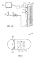
- FIG. 1A A system according to one embodiment of the invention is schematically illustrated in Fig. 1A .
- the system includes, for example, an in vivo device 101 having a steerable receiver 111, a signal source 102, a controller 105 having a user control, such as a joystick or handle, 104, for controlling the signal source and, typically, a monitor or display 103.
- the in vivo device 101 in the embodiment illustrated in Fig. 1A , is typically an endoscope or catheter that is inserted into a patient 110 for imaging and possibly otherwise sensing body lumens, such as the GI tract, blood vessels, the reproductive tract or any other suitable body lumens.
- the device 101 is flexible, in particular near its distal end.
- the device 101 may include typical controls, such as pulleys. In alternate embodiments, the device may be other devices, with other structures.
- the in vivo device 101 typically includes a steerable receiver 111 that is typically located at the leading end 101' of the in vivo device 101.
- the steerable receiver 111 receives a signal 112 from the signal source 102 and may be rotated or moved according to such signal 112, which may include, for example, the vector and possibly other parameters.
- Other user controls may be used, such as buttons, graphical user interfaces used with computers, etc.
- the signal source 102 generates a signal 112. Typically the signal source 102 generates a variable magnetic field.
- Fig. 1B is a schematic depiction of a steerable receiver according to an embodiment of the present invention.
- the steerable receiver 111 typically includes a magnetic receiver 115 including one or more coils or magnets or magnetized material and typically having a dipole which, for example, may be influenced by, manipulated by, or moved by the magnetic field induced by the signal source 102, and may be aligned by this magnetic field.
- the materials used may be any suitable material influenced by a magnetic field.
- the signal source 102 can include an AC induction coil, e.g., a low frequency AC induction coil (about 60Hz) or may have a rotating magnetic circuit to generate a varying magnetic field.
- an AC induction coil e.g., a low frequency AC induction coil (about 60Hz) or may have a rotating magnetic circuit to generate a varying magnetic field.
- the practical frequency range may be from several tens of Hz to several tens of KHz.
- the signal source 102 which may be, for example, a stationary or a mobile portable source, is placed in proximity to the patient's body, typically generating an electromagnetic field that substantially surrounds the patient's body. In other embodiments, the field need only surround the relevant portion of the patient, for example the abdomen. A magnetic field can be generated continuously or when necessary.
- the in vivo device 101 typically includes an image sensor (not shown) such as a CCD or a CMOS image sensor, one or more illumination source(s) for illuminating an in vivo site (not shown) and optionally a transmitter (not shown) for, typically, wirelessly transmitting image data to a receiving/processing unit (not shown).
- the transmitter may operate by, for example, radio waves.
- image data may be communicated through other systems, such as a wired connection to a receiving/processing unit (not shown).
- the receiving/processing unit may show an image or moving images on display 103, which may be, for example, a conventional monitor. Other methods and systems of image display may be used.
- the in vivo device 101 may include other sensors, such as a pH meter, temperature sensors, pressure sensors and so on, for sensing the endo-luminal environment. Sensed endo-luminal conditions may also be transmitted (wirelessly or not) to a receiving/processing unit and may be indicated on display 103. The same transmitter can be used for transmitting, for example, positional information and image (or other) data. Such positional information may typically include three dimensional or six degrees of freedom position information
- An operator can view the images and other information indicated on display 103 and can control the signal source 102 by manipulating control 104, to induce a signal having a desired vector and/or amplitude so as to steer the leading end 101' of the in vivo device to a desired location and/or position.
- in vivo sensing systems that can be utilized in the present invention are described in US Patent Number 5,604,531 to Iddan and in International Application Publication No. WO 01/65995 , both of which are assigned to the common assignee of the present invention.
- the systems described above may be battery operated and wireless or may be connected to a power supply and/or light source external to the patient's 110 body.
- a capsule as described in International Application Publication No. WO 01/65995 may be located at or near the leading end 101' to provide image or other information to the monitor 103.
- FIG. 2 An in vivo device in accordance with another embodiment of the invention is schematically illustrated in Fig. 2 .
- the in vivo device 20 is, typically, a swallowable capsule, such as one similar to the embodiments described in the above mentioned US Patent Number 5,604,531 and International Application Publication No. WO 01/65995 .
- the in-vivo device may be similar to systems other than described in US Patent Number 5,604,531 and International Application Publication No. WO 01/65995 .
- the imaging device 20 includes, for example, an illumination unit, typically including one or more illumination source(s) such as white LEDs 23A and 23B, an image sensor 24, a transmitter 26 for transmitting image signals of the image sensor 24, a steerable transceiver 27, and a power source 25, such as a silver oxide battery, that provides power to the entirety of the electrical elements of the imaging device 20.
- an illumination unit typically including one or more illumination source(s) such as white LEDs 23A and 23B
- an image sensor 24 for transmitting image signals of the image sensor 24, a steerable transceiver 27, and a power source 25, such as a silver oxide battery, that provides power to the entirety of the electrical elements of the imaging device 20.
- a power source 25 such as a silver oxide battery
- the in vivo device 20 is typically capsule shaped, and typically can be easily swallowed and may passively pass through the entire GI tract. While passing through tube-like portions of the GI tract, such as the small intestine, the in vivo device 20 may be pushed along by natural peristalsis and may be restricted by the tube walls to a fixed orientation. As the in vivo device 20 passes through the small intestine it periodically images the tube wall. However, when the in vivo device 20 reaches cavities such as the stomach or the large intestine it may not be restricted by the lumen walls and it may, for example, rotate and tumble through the lumen. Also, in these lumens the natural movement may not always be effective in moving the capsule shaped device.
- a signal source such as a variable electromagnetic field generator that can be controlled by an external operator or automatically by a processing unit, transmits signals of varied vectors and amplitudes to the in vivo device 20 and moves the steerable transceiver 27 according to the signals sent.
- Methods of manipulating devices via signals, such as magnetic fields, are known in the art.
- the movement of the steerable transceiver 27 may, for example, cause the entire in vivo device 20 to be moved in a desired direction, pitch, yaw, roll etc.
- the direction, force, velocity and orientation of the in vivo device 20 may be controlled. For example, increasing the variable magnetic vector of the signal may steer the in vivo device in the direction of the signal vector.
- the desired direction can be determined by an external operator or automatically, in accordance with position or other data of the in vivo device 20.
- the processing unit may be part of a feedback cycle in which positional data and/or in vivo environment data can induce a specific signal.
- the location or position of the device may be determined, for example by the processing unit (as further detailed below). If the location or position of the device is undesired (e.g., the device is facing and sensing one wall of a body lumen whereas it is desired to sense other walls of the body lumen) the processing unit can communicate a command, such as an electric or any other suitable (such as microwave, IR etc.) signal, to a processor in the signal source to transmit a signal having a vector and/or amplitude appropriate for steering the in vivo device in a desired direction or to a desired location and/or position.
- a command such as an electric or any other suitable (such as microwave, IR etc.) signal
- environmental conditions such as in vivo pH or temperature, as determined by an in vivo sensor, may indicate that it is desirable for the in vivo device to be slowed down for further inspection of the specific site.
- the processing unit may be triggered by any of these environmental conditions to communicate a command, as described above, and a signal may be induced accordingly.
- an in vivo device can be programmed to follow a predefined route in vivo.
- a predetermined route may include pre-programmed parameters, such as, the time period the device should spend in different portions of the in vivo route.
- the route of the device in vivo can be corrected in response to on line positional or other data received from the in vivo device.
- an ingestible capsule may be delayed in a specific portion of the GI tract, such as in the sack-like secum.
- Positional information sent from the capsule compared, for example, with a time analysis of the capsule stay in the body, may indicate to an operator that the capsule has not yet reached an expected portion of the GI tract and the capsule may be manoeuvered by the operator to exit the secum to resume its passage through the GI tract.
- the in vivo device is an imaging device that periodically images a body lumen, and the route of the device in vivo can be controlled in accordance with the real time images that are received from the device.
- the in vivo imaging device can be controlled, according to embodiments of the invention and as described above, to be slowed down, retreated, turned etc.
- an in vivo device can be slowed down or fully arrested, retreated, turned etc. for obtaining a sample or releasing a substance, such as a probe or a medicament, at a site determined to be suitable, by images or other environmental indications.
- the location and/or position of the in vivo device 20 can be determined by, for example, utilizing the steerable transceiver 27.
- Known methods for determining the in vivo position of objects can be utilized in embodiments of the present invention. Examples of position monitoring systems that can be easily adjusted for use with embodiments of the present invention are described in US Patent 5,697,377 to Wittkampf , US Patent 5,515,853 to Smith and US Patent 6,188,355 to Gilboa . Other methods may be used. Examples of calculation methods for determining the three dimensional position or location of a device containing transceiver 27 that are applicable in embodiments of the present invention are described in WO 01/06917 to Gilboa and WO 00/10456 to Blecher et al. Other methods may be used. It will be appreciated that such position calculations may be carried out on suitable computational or processing devices.
- the steerable transceiver 27 may include three electrodes, coils or transponders that receive electromagnetic signals transmitted from an external source.
- the external source may include three electromagnetic transmitters, each located at a fixed position in an external reference frame that transmit three distinguishable electromagnetic radiations (such as at different frequencies).
- the three electrodes, coils or transponders receive signals corresponding to the electromagnetic radiations at a plurality of times, each of the signals including components of at least one of the three radiations.
- the three electrodes, coils or transponders form functions that include the components of the signal received by the each electrode from the three transmitters.
- the position and the orientation of the in vivo device 20 can be inferred from the functions, as further elaborated in the above mentioned US Patent Number 6,188,355 .
- position monitoring systems and methods may be used with embodiments of the present invention, such as through using monitors that include ultrasound transceivers or monitors that include three magnetic coils that receive and transmit positional signals relative to an external constant magnetic field
- monitors that include ultrasound transceivers or monitors that include three magnetic coils that receive and transmit positional signals relative to an external constant magnetic field
- magnetic marker monitoring techniques may be used as described in a paper published by Weitschies et al. ( Weitschies et al (2001) European Journal of Pharmaceutical Sciences 13, 411 - 416 ).
- Imaging device 30 includes, for example, a body 31 having an optical window 35.
- the imaging device 30 includes an image sensor 32 (e.g., a CMOS or CCD) and an optical system, which typically includes lenses (not shown) and one or more illumination source(s) 33A and 33B, all of which are positioned behind the optical window 35.
- the imaging device 30 includes a steerable receiver 36, for example, as described above, and a transmitter 34 for transmitting image or other data to a receiving system, which is external to a patient's body.
- the transmitter may operate by, for example, radio waves.
- Imaging device 30 is typically powered through a wire 37 that extends from the rear end of body 31 and that is connected to a power source, typically external to a patient's body (not shown). Also, imaging device 30, specifically the illumination source(s) 33A and 33B, may be connected to a light source external to a patient's body (not shown), through, for example, optical fibers 39. Alternately, light sources internal to the imaging device, such as LEDs, may be used. Additional wires or tubes can be extended from body 31, for example, working channels or a wire connected to an external receiving system for receiving data from the transmitter 34.
- Imaging device 30 can be inserted in a body lumen for in vivo imaging of the lumen.
- imaging device 30 can be inserted into a patient's GI tract for imaging the GI tract.
- the imaging device's 30 route in the GI tract is may be limited due to, for example, the wires 37 and 39 extending from it.
- the imaging device 30, which can be of a smaller diameter and more easily manoeuvered than devices presently used for examining the GI tract, may enable close scrutiny of the GI tract which is an improvement over known methods of examining the large intestine, such as endoscopy or colonoscopy.
- a device as described above can be manoeuvered through the large intestine by being inserted into a patient much like a suppository is inserted and by being "pulled” through the large intestine according to an embodiment of the method of the invention.
- an endoscope can be manoeuvered through a patient's intestine, eliminating the need to push the endoscope in a manner that is painful to the patient.
- a system according to embodiments of the invention may aid the pushing.
- FIG. 4A A system according to another embodiment of the invention is schematically illustrated in Figs. 4A and 4B .
- a patient 401 swallows a capsule 41 as described above. While the capsule 41 is sensing the patient's 401 GI tract the patient 401 is, for example, seated or laid on a seat or bed 43, or wears a garment which includes a magnetic field generator 45, a processing and control unit 47 and possibly a position monitoring system, such as or similar to the systems described above.
- a magnetic field can be generated continuously or when necessary.
- the processing and control unit 47 is, for example, input with positional data from the monitoring system or is controlled by an external operator to manoeuver the capsule 41 to a desired location or three dimensional position.
- the processing and control unit 47 may generate a first signal that is sent to the device, for manoeuvering the device at a known direction or velocity.
- the first signal is a known signal with an expected end result on the capsule 41 position.
- the processing and control unit 47 can correct the position of the capsule 41 by, for example, comparing the first generated signal (which is expected to bring the device to a certain position) and the actual position of the capsule 41 at any given moment (as determined, for example, by the position monitoring system).
- the processing and control unit 47 can determine that the capsule is not moving. This may be determined for example, by the above described comparison between the expected and actual position after sending a first signal, or by utilizing a motion detector in the device, or by comparing positional information or image information at different time points or by other methods known in the art.
- An automatic command from the processing and control unit 47 can be sent to the magnetic field generator 45 to transmit a signal of an amplitude and vector that will be enough to move or rotate the capsule 41 but not, for example, to harm the GI tract wall.
- an operator can be alerted by the processing and control unit 47 that the capsule 41 is not moving and the operator can manually (for example with a joy stick) command an appropriate signal to be generated.
- the operator can be aided by real time images that are transmitted from the capsule 41.
- a magnetic field generator 45, a processing and control unit 47 and a position monitoring system can be incorporated into a garment, such as a belt or jacket 44 worn around the appropriate area of the patient's 401 body.
- the system is portable and a patient 401 is free to move about while the capsule 41 is sensing the GI tract.
- a number of reference points are typically attached to the patient 401 (such as antennas 46 attached to a plurality of points on the patient's body) for the processing and control unit 47 to be able to take into account artifacts generated by the patient's movements.
Abstract
Description
- The present invention relates to the field of in vivo devices. More specifically, the present invention relates to a system for positioning and controlling a device in vivo.
- In vivo devices can be used in diagnostic and/or therapeutic processes with minimal intrusion. These devices may include in vivo tools or sensors, such as in vivo imaging devices, in vivo pH meters etc. Typically, in vivo devices, such as endoscopes, are advanced through a body lumen by being pushed or pulled by an external operator. Autonomous in vivo devices, such as gastrointestinal capsules, are typically moved through the gastrointestinal (GI) tract by the natural action of peristalsis. Autonomous devices typically include an internal power source, such as a battery. However, transfer of energy from an external source to in vivo devices is possible. For example, an external time-varied magnetic field may be created in the vicinity of a body in which a device has an electric generator disposed within the device. The magnetic field is typically used to rotate a rotor inside the device, the rotated rotor then being used to generate electric current. Another external pumped power source may be a remote microwave delivery system comprising EM antennae or receivers with high absorption coefficient and resonance geometrical arrangement built inside the device to collect external microwave energy at a designated wavelength. Still another external pumped power source is a remote ultrasound delivery system comprising piezoelectric receivers built inside the device to collect external ultrasonic energy to power the device and to charge-up an internal battery.
- Document
DE 4 313 843 discloses a system for controlling and manoeuvring a capsule. - There is a need for an improved system and method for controlling and manoeuvering in vivo devices.
- Embodiments of the present invention provide a system and method for controlling a device in vivo. Optionally, embodiments of the system and method are used for locating and/or positioning a device in vivo. Typically, embodiments of the system and method of the invention utilize an element, such as a steerable receiver for controlling the movement of a device, including the direction, force and velocity of the device movement.
- Generally, the term "location" refers to the place of the device in relation to a patient's anatomy whereas the term "position" refers to the three dimensional location of the device typically with six degrees of freedom, much the same as used to describe the manoeuvers of, for example, a remotely piloted vehicle (RPV).
- A system according to an embodiment of the invention includes an in vivo device and a signal source. The in vivo device includes a steerable receiver and the signal source, which is typically external to a patient's body, transmits at least a first signal having a first vector that is received by the steerable receiver. The steerable receiver responds to the signal by, for example, rotating or otherwise moving in accordance with the vector of the signal. Furthermore, other components of the signal, for example the amplitude of the signal, can effect the movement of the device. The rotary or other motion of the receiver will, in turn, cause the in vivo device to be steered in accordance with the signal.
- According to a further embodiment of the invention the in vivo device includes, in addition to the steerable receiver, a transmitter which can transmit at least a first positional signal to an external receiving system. Alternately, the in vivo device may include a steerable transceiver for transmitting a positional signal and for receiving a signal having a vector. Thus, the location and/or position of the in vivo device can be determined, for example, by receiving at least one positional signal from the transmitter or transceiver and the in vivo device can be steered in accordance with the determined location and/or position of the in vivo device. The system may further include a processing unit that is in communication with the receiving system for calculating the location and/or position of the in vivo device. The processing unit may also be in communication with an in vivo sensor for processing data relating to the in vivo environment. Furthermore, the processing unit may be in communication with the signal source for inducing a signal.
- A method according to an embodiment includes the steps of exposing an in vivo device, which includes a steerable receiver, to at least one signal having a vector and receiving the at least one signal via the steerable receiver. The method may further include the steps of transmitting at least one positional signal for determining the location and/or position of the in vivo device prior to the step of exposing an in vivo device to at least one signal having a vector. Further, the method may include the steps of processing the positional signal and communicating a command to a signal source to transmit a signal having a vector in accordance with the processed positional signal.
- The signal having a vector is typically a component of an electric or electromagnetic field and the steerable receiver or transceiver is typically a coil or magnet having a dipole.
- According to one embodiment of the invention the system includes an autonomous in vivo device, optionally an in vivo sensing device, such as an image sensor, a pH meter, a pressure detector, a thermometer etc., which includes at least one steerable receiver for receiving a signal having a vector and a signal source for generating at least one signal having a vector. The in vivo device may also include at least one transmitter for transmitting position information, typically three dimensional or six degrees of freedom position information, of the autonomous in vivo device at any given time and/or for transmitting data from the sensing device; a receiving unit for receiving position information and optionally for receiving data from the sensing device; and a processing unit for computing the position and/or orientation of the imaging device at any given time and/or for controlling the signal source. The signal having a vector and/or the position information and/or the data from the sensing device can be transmitted wirelessly or through a wired connection to a receiving unit. The autonomous in vivo device may be a swallowable capsule capable of sensing the GI environment and/or capable of performing in vivo procedures.
- According to one embodiment of the invention the system includes a swallowable capsule for imaging the gastrointestinal (GI) tract. The capsule electrical elements, which are typically battery powered, include an illumination unit for illuminating in vivo sites, an image sensor for obtaining in vivo images, a steerable receiver for receiving a signal having a vector and a transmitter for wirelessly transmitting image data and position data to an external processing unit. Alternately, the capsule includes a steerable transceiver for transmitting position information and receiving a signal having a vector and a separate transmitter for transmitting image data. Such an in vivo image sensor can provide an external operator with a real time view of a body lumen. The signal having a vector can be controlled by the external operator (e.g., by using a joy stick) enabling the operator to manoeuver the image sensor to any part of the lumen guided by the real time images of the lumen.
- The present invention will be understood and appreciated more fully from the following detailed description taken in conjunction with the drawings in which:
-
Figure 1A is a schematic illustration of a system according to an embodiment of the invention; -
Figure 1B is a schematic depiction of a steerable receiver according to an embodiment of the present invention; -
Figure 2 is a schematic illustration of an in vivo device according to an embodiment of the invention; -
Figure 3 is a schematic illustration of a device in accordance with another embodiment of the invention; and -
Figures 4A and B are schematic illustrations of a system according to additional embodiments of the invention; inFig. 4A with a stationary signal source and inFig. 4B with a mobile or portable signal source. - In the following description, various aspects of the present invention will be described. For purposes of explanation, specific configurations and details are set forth in order to provide a thorough understanding of the present invention. However, it will also be apparent to one skilled in the art that the present invention may be practiced without the specific details presented herein. Furthermore, well known features may be omitted or simplified in order not to obscure the present invention.
- Embodiments of the present invention may enable movement of a diagnostic and/or therapeutic device, such as a swallowable video capsule, an endoscope, a needle, a stent etc. Movement may be facilitated, through, for example, difficult to access parts of the body.
- A system according to one embodiment of the invention is schematically illustrated in
Fig. 1A . The system includes, for example, an invivo device 101 having asteerable receiver 111, a signal source 102, acontroller 105 having a user control, such as a joystick or handle, 104, for controlling the signal source and, typically, a monitor ordisplay 103. The invivo device 101, in the embodiment illustrated inFig. 1A , is typically an endoscope or catheter that is inserted into apatient 110 for imaging and possibly otherwise sensing body lumens, such as the GI tract, blood vessels, the reproductive tract or any other suitable body lumens. Typically, thedevice 101 is flexible, in particular near its distal end. Thedevice 101 may include typical controls, such as pulleys. In alternate embodiments, the device may be other devices, with other structures. - The in
vivo device 101 typically includes asteerable receiver 111 that is typically located at the leading end 101' of the invivo device 101. Thesteerable receiver 111 receives asignal 112 from the signal source 102 and may be rotated or moved according tosuch signal 112, which may include, for example, the vector and possibly other parameters. Other user controls may be used, such as buttons, graphical user interfaces used with computers, etc. - The signal source 102 generates a
signal 112. Typically the signal source 102 generates a variable magnetic field.Fig. 1B is a schematic depiction of a steerable receiver according to an embodiment of the present invention. Thesteerable receiver 111 typically includes amagnetic receiver 115 including one or more coils or magnets or magnetized material and typically having a dipole which, for example, may be influenced by, manipulated by, or moved by the magnetic field induced by the signal source 102, and may be aligned by this magnetic field. The materials used may be any suitable material influenced by a magnetic field. The signal source 102 can include an AC induction coil, e.g., a low frequency AC induction coil (about 60Hz) or may have a rotating magnetic circuit to generate a varying magnetic field. In order to achieve higher efficiency of the energy transmission it may be desirable to operate in a relatively high frequency range. However, due to high attenuation of the body tissues at high frequencies - the practical frequency range may be from several tens of Hz to several tens of KHz. - The signal source 102, which may be, for example, a stationary or a mobile portable source, is placed in proximity to the patient's body, typically generating an electromagnetic field that substantially surrounds the patient's body. In other embodiments, the field need only surround the relevant portion of the patient, for example the abdomen. A magnetic field can be generated continuously or when necessary.
- The in
vivo device 101 typically includes an image sensor (not shown) such as a CCD or a CMOS image sensor, one or more illumination source(s) for illuminating an in vivo site (not shown) and optionally a transmitter (not shown) for, typically, wirelessly transmitting image data to a receiving/processing unit (not shown). The transmitter may operate by, for example, radio waves. Alternately, image data may be communicated through other systems, such as a wired connection to a receiving/processing unit (not shown). The receiving/processing unit may show an image or moving images ondisplay 103, which may be, for example, a conventional monitor. Other methods and systems of image display may be used. The invivo device 101 may include other sensors, such as a pH meter, temperature sensors, pressure sensors and so on, for sensing the endo-luminal environment. Sensed endo-luminal conditions may also be transmitted (wirelessly or not) to a receiving/processing unit and may be indicated ondisplay 103. The same transmitter can be used for transmitting, for example, positional information and image (or other) data. Such positional information may typically include three dimensional or six degrees of freedom position information - An operator can view the images and other information indicated on
display 103 and can control the signal source 102 by manipulatingcontrol 104, to induce a signal having a desired vector and/or amplitude so as to steer the leading end 101' of the in vivo device to a desired location and/or position. - Examples of in vivo sensing systems that can be utilized in the present invention are described in
US Patent Number 5,604,531 to Iddan and in International Application Publication No.WO 01/65995 WO 01/65995 monitor 103. - An in vivo device in accordance with another embodiment of the invention is schematically illustrated in
Fig. 2 . The invivo device 20 is, typically, a swallowable capsule, such as one similar to the embodiments described in the above mentionedUS Patent Number 5,604,531 and International Application Publication No.WO 01/65995 US Patent Number 5,604,531 and International Application Publication No.WO 01/65995 imaging device 20 includes, for example, an illumination unit, typically including one or more illumination source(s) such aswhite LEDs image sensor 24, atransmitter 26 for transmitting image signals of theimage sensor 24, asteerable transceiver 27, and a power source 25, such as a silver oxide battery, that provides power to the entirety of the electrical elements of theimaging device 20. Other components and configurations of components may be used. - The in
vivo device 20 is typically capsule shaped, and typically can be easily swallowed and may passively pass through the entire GI tract. While passing through tube-like portions of the GI tract, such as the small intestine, the invivo device 20 may be pushed along by natural peristalsis and may be restricted by the tube walls to a fixed orientation. As the invivo device 20 passes through the small intestine it periodically images the tube wall. However, when the invivo device 20 reaches cavities such as the stomach or the large intestine it may not be restricted by the lumen walls and it may, for example, rotate and tumble through the lumen. Also, in these lumens the natural movement may not always be effective in moving the capsule shaped device. - According to an embodiment of the invention, a signal source, such as a variable electromagnetic field generator that can be controlled by an external operator or automatically by a processing unit, transmits signals of varied vectors and amplitudes to the in
vivo device 20 and moves thesteerable transceiver 27 according to the signals sent. Methods of manipulating devices via signals, such as magnetic fields, are known in the art. The movement of thesteerable transceiver 27 may, for example, cause the entire invivo device 20 to be moved in a desired direction, pitch, yaw, roll etc. In one embodiment, the direction, force, velocity and orientation of the invivo device 20 may be controlled. For example, increasing the variable magnetic vector of the signal may steer the in vivo device in the direction of the signal vector. The desired direction can be determined by an external operator or automatically, in accordance with position or other data of the invivo device 20. - The processing unit may be part of a feedback cycle in which positional data and/or in vivo environment data can induce a specific signal. For example, the location or position of the device may be determined, for example by the processing unit (as further detailed below). If the location or position of the device is undesired (e.g., the device is facing and sensing one wall of a body lumen whereas it is desired to sense other walls of the body lumen) the processing unit can communicate a command, such as an electric or any other suitable (such as microwave, IR etc.) signal, to a processor in the signal source to transmit a signal having a vector and/or amplitude appropriate for steering the in vivo device in a desired direction or to a desired location and/or position. In another case, environmental conditions, such as in vivo pH or temperature, as determined by an in vivo sensor, may indicate that it is desirable for the in vivo device to be slowed down for further inspection of the specific site. The processing unit may be triggered by any of these environmental conditions to communicate a command, as described above, and a signal may be induced accordingly.
- In accordance with an embodiment of the invention, an in vivo device can be programmed to follow a predefined route in vivo. A predetermined route may include pre-programmed parameters, such as, the time period the device should spend in different portions of the in vivo route. Alternately, the route of the device in vivo can be corrected in response to on line positional or other data received from the in vivo device. For example, an ingestible capsule, according to one embodiment of the invention, may be delayed in a specific portion of the GI tract, such as in the sack-like secum. Positional information sent from the capsule compared, for example, with a time analysis of the capsule stay in the body, may indicate to an operator that the capsule has not yet reached an expected portion of the GI tract and the capsule may be manoeuvered by the operator to exit the secum to resume its passage through the GI tract. In accordance with another embodiment of the invention the in vivo device is an imaging device that periodically images a body lumen, and the route of the device in vivo can be controlled in accordance with the real time images that are received from the device. The in vivo imaging device can be controlled, according to embodiments of the invention and as described above, to be slowed down, retreated, turned etc. for obtaining additional images of a site, for example a site of a suspected pathology, that was imaged by the device. Also, an in vivo device can be slowed down or fully arrested, retreated, turned etc. for obtaining a sample or releasing a substance, such as a probe or a medicament, at a site determined to be suitable, by images or other environmental indications.
- The location and/or position of the in
vivo device 20 can be determined by, for example, utilizing thesteerable transceiver 27. Known methods for determining the in vivo position of objects can be utilized in embodiments of the present invention. Examples of position monitoring systems that can be easily adjusted for use with embodiments of the present invention are described inUS Patent 5,697,377 to Wittkampf ,US Patent 5,515,853 to Smith andUS Patent 6,188,355 to Gilboa . Other methods may be used. Examples of calculation methods for determining the three dimensional position or location of adevice containing transceiver 27 that are applicable in embodiments of the present invention are described inWO 01/06917 to Gilboa WO 00/10456 to Blecher et al. - In one embodiment, the
steerable transceiver 27 may include three electrodes, coils or transponders that receive electromagnetic signals transmitted from an external source. The external source may include three electromagnetic transmitters, each located at a fixed position in an external reference frame that transmit three distinguishable electromagnetic radiations (such as at different frequencies). The three electrodes, coils or transponders receive signals corresponding to the electromagnetic radiations at a plurality of times, each of the signals including components of at least one of the three radiations. The three electrodes, coils or transponders form functions that include the components of the signal received by the each electrode from the three transmitters. The position and the orientation of the invivo device 20 can be inferred from the functions, as further elaborated in the above mentionedUS Patent Number 6,188,355 . - Other position monitoring systems and methods may be used with embodiments of the present invention, such as through using monitors that include ultrasound transceivers or monitors that include three magnetic coils that receive and transmit positional signals relative to an external constant magnetic field For example, magnetic marker monitoring techniques may be used as described in a paper published by Weitschies et al. (Weitschies et al (2001) European Journal of Pharmaceutical Sciences 13, 411 - 416).
- An in vivo device according to another embodiment of the invention is schematically described in
Fig. 3 .Imaging device 30 includes, for example, abody 31 having anoptical window 35. Theimaging device 30 includes an image sensor 32 (e.g., a CMOS or CCD) and an optical system, which typically includes lenses (not shown) and one or more illumination source(s) 33A and 33B, all of which are positioned behind theoptical window 35. Further, theimaging device 30 includes asteerable receiver 36, for example, as described above, and atransmitter 34 for transmitting image or other data to a receiving system, which is external to a patient's body. The transmitter may operate by, for example, radio waves.Imaging device 30 is typically powered through awire 37 that extends from the rear end ofbody 31 and that is connected to a power source, typically external to a patient's body (not shown). Also,imaging device 30, specifically the illumination source(s) 33A and 33B, may be connected to a light source external to a patient's body (not shown), through, for example,optical fibers 39. Alternately, light sources internal to the imaging device, such as LEDs, may be used. Additional wires or tubes can be extended frombody 31, for example, working channels or a wire connected to an external receiving system for receiving data from thetransmitter 34. -
Imaging device 30 can be inserted in a body lumen for in vivo imaging of the lumen. For example,imaging device 30 can be inserted into a patient's GI tract for imaging the GI tract. The imaging device's 30 route in the GI tract is may be limited due to, for example, thewires imaging device 30, which can be of a smaller diameter and more easily manoeuvered than devices presently used for examining the GI tract, may enable close scrutiny of the GI tract which is an improvement over known methods of examining the large intestine, such as endoscopy or colonoscopy. For example, a device as described above can be manoeuvered through the large intestine by being inserted into a patient much like a suppository is inserted and by being "pulled" through the large intestine according to an embodiment of the method of the invention. In the same manner, an endoscope can be manoeuvered through a patient's intestine, eliminating the need to push the endoscope in a manner that is painful to the patient. Alternately, a system according to embodiments of the invention may aid the pushing. - A system according to another embodiment of the invention is schematically illustrated in
Figs. 4A and 4B . As shown inFig. 4A , apatient 401 swallows acapsule 41 as described above. While thecapsule 41 is sensing the patient's 401 GI tract thepatient 401 is, for example, seated or laid on a seat orbed 43, or wears a garment which includes amagnetic field generator 45, a processing andcontrol unit 47 and possibly a position monitoring system, such as or similar to the systems described above. A magnetic field can be generated continuously or when necessary. - The processing and
control unit 47 is, for example, input with positional data from the monitoring system or is controlled by an external operator to manoeuver thecapsule 41 to a desired location or three dimensional position. In one embodiment, the processing andcontrol unit 47 may generate a first signal that is sent to the device, for manoeuvering the device at a known direction or velocity. The first signal is a known signal with an expected end result on thecapsule 41 position. The processing andcontrol unit 47 can correct the position of thecapsule 41 by, for example, comparing the first generated signal (which is expected to bring the device to a certain position) and the actual position of thecapsule 41 at any given moment (as determined, for example, by the position monitoring system). For example, when thecapsule 41 movement in the GI tract is stopped (due to, for example, being blocked by the GI tract wall or due to not being moved by the natural movement of the intestine), the processing andcontrol unit 47 can determine that the capsule is not moving. This may be determined for example, by the above described comparison between the expected and actual position after sending a first signal, or by utilizing a motion detector in the device, or by comparing positional information or image information at different time points or by other methods known in the art. An automatic command from the processing andcontrol unit 47 can be sent to themagnetic field generator 45 to transmit a signal of an amplitude and vector that will be enough to move or rotate thecapsule 41 but not, for example, to harm the GI tract wall. Alternately, an operator can be alerted by the processing andcontrol unit 47 that thecapsule 41 is not moving and the operator can manually (for example with a joy stick) command an appropriate signal to be generated. The operator can be aided by real time images that are transmitted from thecapsule 41. - In an alternate embodiment, schematically shown in
Fig. 4B , amagnetic field generator 45, a processing andcontrol unit 47 and a position monitoring system can be incorporated into a garment, such as a belt orjacket 44 worn around the appropriate area of the patient's 401 body. Thus, the system is portable and apatient 401 is free to move about while thecapsule 41 is sensing the GI tract. In this embodiment a number of reference points are typically attached to the patient 401 (such asantennas 46 attached to a plurality of points on the patient's body) for the processing andcontrol unit 47 to be able to take into account artifacts generated by the patient's movements. - It will be appreciated by persons skilled in the art that the present invention is not limited by what has been particularly shown and described herein above. Rather the scope of the invention is defined by the claims which follow.
Claims (6)
- A system for manoeuvring a swallowable imaging capsule (20, 30, 41) in vivo, the system comprising:- a swallowable imaging capsule (20, 30, 41), said capsule (20, 30, 41) comprising:- a steering element (27, 36, 111), said steering element (27, 36, 111) being manoeuvrable by a magnetic field (112) ;- an image sensor (24, 32);- an illumination source (23A, 23B, 33A, 33B) ; and- a transmitter (26, 34) for wirelessly transmitting image data of the image sensor (24, 32) ; and- a receiving system; and- a signal source (45, 102), located externally to a patient's body (110, 401), configured for generating a variable magnetic field (112) to manoeuvre the steering element (27, 36, 111) ; and- a processing unit (47) in communication with the receiving system;characterised in that- the transmitter (26, 34) is adapted to wirelessly transmit at least one position signal;- the receiving system is adapted to receive the transmitted position signal; and- the processing unit (47) is in communication with the signal source (45, 102)and is configured to:- determine a current position of the imaging capsule (20, 30, 41) using the position signal;- automatically determine a desired position for the imaging capsule;- compare the current position of the imaging capsule (20, 30, 41) with the desired position for the imaging capsule (20, 30, 41) after sending a first signal for manoeuvring the capsule at a known direction or velocity; and- based on the comparison, to communicate an automatic command signal to the signal source (45, 102) to manoeuvre the steering element (27, 36, 111) to move the capsule (20, 30, 41) to the desired position.
- The system of claim 1, wherein the steering element (27, 36, 111) is a coil.
- The system of claim 1, wherein the steering element (27, 36, 111) is a magnet having a dipole.
- The system of claim 1, wherein the signal source (45, 102) is a variable electromagnetic field generator.
- The system of claim 1 further comprising an external source and wherein the steerable element is a steerable transceiver comprising three electrodes, coils or transponders configured to receive electromagnetic signals transmitted from the external source.
- The system of claim 5, wherein the external source comprises three electromagnetic transmitters, each of which is located at a fixed position in an external reference frame and each of which transmits a distinguishable electromagnetic radiation.
Applications Claiming Priority (3)
| Application Number | Priority Date | Filing Date | Title |
|---|---|---|---|
| US32406701P | 2001-09-24 | 2001-09-24 | |
| US324067P | 2001-09-24 | ||
| PCT/IL2002/000784 WO2003028224A2 (en) | 2001-09-24 | 2002-09-24 | System and method for controlling a device in vivo |
Publications (3)
| Publication Number | Publication Date |
|---|---|
| EP1432345A2 EP1432345A2 (en) | 2004-06-30 |
| EP1432345A4 EP1432345A4 (en) | 2008-11-26 |
| EP1432345B1 true EP1432345B1 (en) | 2011-11-09 |
Family
ID=23261916
Family Applications (1)
| Application Number | Title | Priority Date | Filing Date |
|---|---|---|---|
| EP02772784A Expired - Lifetime EP1432345B1 (en) | 2001-09-24 | 2002-09-24 | System for controlling a device in vivo |
Country Status (7)
| Country | Link |
|---|---|
| US (1) | US7907986B2 (en) |
| EP (1) | EP1432345B1 (en) |
| JP (1) | JP4796275B2 (en) |
| AT (1) | ATE532453T1 (en) |
| AU (1) | AU2002337591A1 (en) |
| IL (1) | IL161058A0 (en) |
| WO (1) | WO2003028224A2 (en) |
Families Citing this family (154)
| Publication number | Priority date | Publication date | Assignee | Title |
|---|---|---|---|---|
| ATE362973T1 (en) * | 1997-11-12 | 2007-06-15 | Bausch & Lomb | CLEANING AND DISINFECTING CONTACT LENSES WITH A BIGUANIDE AND A BORATE PHOSPHATE BUFFER |
| IL132944A (en) | 1999-11-15 | 2009-05-04 | Arkady Glukhovsky | Method for activating an image collecting process |
| KR100800040B1 (en) | 2000-03-08 | 2008-01-31 | 기븐 이미징 리미티드 | A capsule for in vivo imaging |
| US7553276B2 (en) * | 2001-01-16 | 2009-06-30 | Given Imaging Ltd. | Method and device for imaging body lumens |
| IL143260A (en) | 2001-05-20 | 2006-09-05 | Given Imaging Ltd | Array system and method for locating an in vivo signal source |
| ATE404114T1 (en) * | 2001-06-18 | 2008-08-15 | Given Imaging Ltd | SWALLOWABLE IN-VIVO CAPSULE WITH A CIRCUIT BOARD HAVING RIGID AND FLEXIBLE SECTIONS |
| WO2003011103A2 (en) * | 2001-08-02 | 2003-02-13 | Given Imaging Ltd. | Apparatus and methods for in vivo imaging |
| US8428685B2 (en) * | 2001-09-05 | 2013-04-23 | Given Imaging Ltd. | System and method for magnetically maneuvering an in vivo device |
| AU2002334354A1 (en) * | 2001-09-05 | 2003-03-18 | Given Imaging Ltd. | System and method for three dimensional display of body lumens |
| JP3756797B2 (en) | 2001-10-16 | 2006-03-15 | オリンパス株式会社 | Capsule type medical equipment |
| US7662094B2 (en) * | 2002-05-14 | 2010-02-16 | Given Imaging Ltd. | Optical head assembly with dome, and device for use thereof |
| EP1534120B1 (en) * | 2002-08-13 | 2010-06-09 | Given Imaging Ltd. | System for in vivo sampling and analysis |
| ATE454092T1 (en) * | 2002-09-27 | 2010-01-15 | Olympus Corp | ULTRASONIC DEVICE |
| US8449452B2 (en) | 2002-09-30 | 2013-05-28 | Given Imaging Ltd. | In-vivo sensing system |
| WO2004028336A2 (en) * | 2002-09-30 | 2004-04-08 | Given Imaging Ltd. | Reduced size imaging device |
| US7866322B2 (en) * | 2002-10-15 | 2011-01-11 | Given Imaging Ltd. | Device, system and method for transfer of signals to a moving device |
| US20080045788A1 (en) * | 2002-11-27 | 2008-02-21 | Zvika Gilad | Method and device of imaging with an in vivo imager |
| US20060155174A1 (en) * | 2002-12-16 | 2006-07-13 | Arkady Glukhovsky | Device, system and method for selective activation of in vivo sensors |
| WO2004058041A2 (en) * | 2002-12-26 | 2004-07-15 | Given Imaging Ltd. | Immobilizable in vivo sensing device |
| US7833151B2 (en) * | 2002-12-26 | 2010-11-16 | Given Imaging Ltd. | In vivo imaging device with two imagers |
| WO2004059568A1 (en) * | 2002-12-26 | 2004-07-15 | Given Imaging Ltd. | In vivo imaging device and method of manufacture thereof |
| JP4149838B2 (en) * | 2003-03-04 | 2008-09-17 | オリンパス株式会社 | Capsule medical device |
| WO2004096008A2 (en) * | 2003-05-01 | 2004-11-11 | Given Imaging Ltd. | Panoramic field of view imaging device |
| IL162740A (en) * | 2003-06-26 | 2010-06-16 | Given Imaging Ltd | Device, method and system for reduced transmission imaging |
| AU2004254764B2 (en) * | 2003-07-02 | 2010-12-09 | Given Imaging Ltd. | Imaging sensor array and device and method for use thereof |
| US7623904B2 (en) | 2003-08-06 | 2009-11-24 | Olympus Corporation | Medical apparatus, medical apparatus guide system, capsule type medical apparatus, and capsule type medical apparatus guide apparatus |
| US20050065441A1 (en) * | 2003-08-29 | 2005-03-24 | Arkady Glukhovsky | System, apparatus and method for measurement of motion parameters of an in-vivo device |
| US9089261B2 (en) | 2003-09-15 | 2015-07-28 | Covidien Lp | System of accessories for use with bronchoscopes |
| EP2316328B1 (en) * | 2003-09-15 | 2012-05-09 | Super Dimension Ltd. | Wrap-around holding device for use with bronchoscopes |
| JP4153852B2 (en) * | 2003-09-18 | 2008-09-24 | オリンパス株式会社 | Energy supply coil and wireless in-vivo information acquisition system using the same |
| DE10343494B4 (en) | 2003-09-19 | 2006-06-14 | Siemens Ag | Magnetically navigable device for use in the field of medical endoscopy |
| US8021356B2 (en) * | 2003-09-29 | 2011-09-20 | Olympus Corporation | Capsule medication administration system, medication administration method using capsule medication administration system, control method for capsule medication administration system |
| US20050137468A1 (en) * | 2003-12-18 | 2005-06-23 | Jerome Avron | Device, system, and method for in-vivo sensing of a substance |
| DE10359981A1 (en) * | 2003-12-19 | 2005-07-21 | Siemens Ag | System and method for in vivo positioning and orientation determination of an endoscopy capsule or an endo-robot in the context of a wireless endoscopy |
| EP1696788B1 (en) * | 2003-12-24 | 2011-08-17 | Given Imaging Ltd. | Device for in-vivo imaging of a body lumen |
| US8639314B2 (en) * | 2003-12-24 | 2014-01-28 | Given Imaging Ltd. | Device, system and method for in-vivo imaging of a body lumen |
| JP4150663B2 (en) * | 2003-12-25 | 2008-09-17 | オリンパス株式会社 | In-subject position detection system |
| JP2005192632A (en) * | 2003-12-26 | 2005-07-21 | Olympus Corp | Subject interior moving state detecting system |
| JP4422476B2 (en) * | 2003-12-26 | 2010-02-24 | オリンパス株式会社 | In-subject position detection system |
| US7647090B1 (en) | 2003-12-30 | 2010-01-12 | Given Imaging, Ltd. | In-vivo sensing device and method for producing same |
| US8142350B2 (en) | 2003-12-31 | 2012-03-27 | Given Imaging, Ltd. | In-vivo sensing device with detachable part |
| JP4455067B2 (en) * | 2004-01-14 | 2010-04-21 | オリンパス株式会社 | Capsule endoscope device |
| US8764725B2 (en) | 2004-02-09 | 2014-07-01 | Covidien Lp | Directional anchoring mechanism, method and applications thereof |
| DE102004023527A1 (en) * | 2004-05-13 | 2005-12-08 | Osypka, Peter, Dr.-Ing. | measuring device |
| US7605852B2 (en) | 2004-05-17 | 2009-10-20 | Micron Technology, Inc. | Real-time exposure control for automatic light control |
| KR100615881B1 (en) * | 2004-06-21 | 2006-08-25 | 한국과학기술연구원 | Capsule Type Endoscope Control System |
| US8500630B2 (en) * | 2004-06-30 | 2013-08-06 | Given Imaging Ltd. | In vivo device with flexible circuit board and method for assembly thereof |
| US9968290B2 (en) * | 2004-06-30 | 2018-05-15 | Given Imaging Ltd. | Apparatus and methods for capsule endoscopy of the esophagus |
| US7336833B2 (en) * | 2004-06-30 | 2008-02-26 | Given Imaging, Ltd. | Device, system, and method for reducing image data captured in-vivo |
| US7596403B2 (en) | 2004-06-30 | 2009-09-29 | Given Imaging Ltd. | System and method for determining path lengths through a body lumen |
| US20060015013A1 (en) * | 2004-06-30 | 2006-01-19 | Zvika Gilad | Device and method for in vivo illumination |
| US7643865B2 (en) * | 2004-06-30 | 2010-01-05 | Given Imaging Ltd. | Autonomous in-vivo device |
| US10646109B1 (en) * | 2004-07-19 | 2020-05-12 | Hypermed Imaging, Inc. | Device and method of balloon endoscopy |
| JP2006075533A (en) * | 2004-09-13 | 2006-03-23 | Olympus Corp | Intra-patient introduction system, receiver, and intra-patient introduction apparatus |
| WO2006040830A1 (en) | 2004-10-15 | 2006-04-20 | Olympus Corporation | Wireless intrasubject information acquiring system |
| US7647109B2 (en) | 2004-10-20 | 2010-01-12 | Boston Scientific Scimed, Inc. | Leadless cardiac stimulation systems |
| EP1812104B1 (en) | 2004-10-20 | 2012-11-21 | Boston Scientific Limited | Leadless cardiac stimulation systems |
| US20060095093A1 (en) * | 2004-11-04 | 2006-05-04 | Ido Bettesh | Apparatus and method for receiving device selection and combining |
| CN103251409B (en) * | 2004-12-17 | 2015-07-22 | 奥林巴斯株式会社 | Medical equipment and magnetic-induction and position-detection system of medical device |
| US8235055B2 (en) * | 2005-01-11 | 2012-08-07 | Uti Limited Partnership | Magnetic levitation of intraluminal microelectronic capsule |
| ES2528722T3 (en) * | 2005-01-27 | 2015-02-12 | Covidien Lp | Endoscope with miniature imaging set |
| US20060217593A1 (en) * | 2005-03-24 | 2006-09-28 | Zvika Gilad | Device, system and method of panoramic multiple field of view imaging |
| IL167782A (en) * | 2005-03-31 | 2011-12-29 | Given Imaging Ltd | Antenna for in-vivo imaging system |
| IL174531A0 (en) * | 2005-04-06 | 2006-08-20 | Given Imaging Ltd | System and method for performing capsule endoscopy diagnosis in remote sites |
| DE102005056560A1 (en) * | 2005-05-09 | 2006-12-07 | Thiel, Christian, Dr. | Taxable Optrone II |
| DE102005032378A1 (en) * | 2005-07-08 | 2007-01-11 | Siemens Ag | Magnetic navigable endoscopy capsule with sensor for detecting a physiological size |
| US9047746B1 (en) | 2005-07-20 | 2015-06-02 | Neil Euliano | Electronic medication compliance monitoring system and associated methods |
| US7796043B2 (en) * | 2005-07-20 | 2010-09-14 | Neil R. Euliano | Medication compliance system and associated methods |
| JP4763439B2 (en) * | 2005-08-08 | 2011-08-31 | オリンパス株式会社 | Medical device magnetic guidance and position detection system |
| US8784336B2 (en) | 2005-08-24 | 2014-07-22 | C. R. Bard, Inc. | Stylet apparatuses and methods of manufacture |
| US20070129602A1 (en) * | 2005-11-22 | 2007-06-07 | Given Imaging Ltd. | Device, method and system for activating an in-vivo imaging device |
| US7896805B2 (en) * | 2005-11-23 | 2011-03-01 | Given Imaging Ltd. | In-vivo imaging device and optical system thereof |
| US20080312502A1 (en) * | 2005-12-02 | 2008-12-18 | Christopher Paul Swain | System and Device for in Vivo Procedures |
| US7848823B2 (en) | 2005-12-09 | 2010-12-07 | Boston Scientific Scimed, Inc. | Cardiac stimulation system |
| US8050774B2 (en) | 2005-12-22 | 2011-11-01 | Boston Scientific Scimed, Inc. | Electrode apparatus, systems and methods |
| US9320417B2 (en) | 2005-12-29 | 2016-04-26 | Given Imaging Ltd. | In-vivo optical imaging device with backscatter blocking |
| US20070167834A1 (en) * | 2005-12-29 | 2007-07-19 | Amit Pascal | In-vivo imaging optical device and method |
| US20070156051A1 (en) * | 2005-12-29 | 2007-07-05 | Amit Pascal | Device and method for in-vivo illumination |
| US9084547B2 (en) | 2006-03-30 | 2015-07-21 | Given Imaging Ltd. | System and method for checking the status of an in-vivo imaging device |
| US20100013914A1 (en) * | 2006-03-30 | 2010-01-21 | Ido Bettesh | In-vivo sensing device and method for communicating between imagers and processor thereof |
| US7937161B2 (en) * | 2006-03-31 | 2011-05-03 | Boston Scientific Scimed, Inc. | Cardiac stimulation electrodes, delivery devices, and implantation configurations |
| US7840281B2 (en) | 2006-07-21 | 2010-11-23 | Boston Scientific Scimed, Inc. | Delivery of cardiac stimulation devices |
| EP2063780B1 (en) * | 2006-09-06 | 2018-04-11 | Innurvation, Inc. | Imaging and locating systems and methods for a swallowable sensor device |
| US8588887B2 (en) * | 2006-09-06 | 2013-11-19 | Innurvation, Inc. | Ingestible low power sensor device and system for communicating with same |
| WO2008030482A2 (en) | 2006-09-06 | 2008-03-13 | Innurvation Inc | System and method for acoustic information exchange involving an ingestible low power capsule |
| US7761134B2 (en) | 2006-10-20 | 2010-07-20 | Given Imaging Ltd. | System and method for modeling a tracking curve of an in vivo device |
| US8388546B2 (en) | 2006-10-23 | 2013-03-05 | Bard Access Systems, Inc. | Method of locating the tip of a central venous catheter |
| US7794407B2 (en) | 2006-10-23 | 2010-09-14 | Bard Access Systems, Inc. | Method of locating the tip of a central venous catheter |
| US20080177141A1 (en) * | 2007-01-24 | 2008-07-24 | Hsien-Ming Wu | Memory-type two-section endoscopic system |
| DE102007007801B4 (en) | 2007-02-16 | 2015-02-26 | Siemens Aktiengesellschaft | Magnetic coil system with a navigation coil system and a location system |
| JP5025720B2 (en) * | 2007-02-22 | 2012-09-12 | オリンパスメディカルシステムズ株式会社 | Intra-subject introduction system |
| US8905920B2 (en) | 2007-09-27 | 2014-12-09 | Covidien Lp | Bronchoscope adapter and method |
| US9197470B2 (en) | 2007-10-05 | 2015-11-24 | Innurvation, Inc. | Data transmission via multi-path channels using orthogonal multi-frequency signals with differential phase shift keying modulation |
| US20090105532A1 (en) * | 2007-10-22 | 2009-04-23 | Zvika Gilad | In vivo imaging device and method of manufacturing thereof |
| US20100268025A1 (en) * | 2007-11-09 | 2010-10-21 | Amir Belson | Apparatus and methods for capsule endoscopy of the esophagus |
| US10449330B2 (en) | 2007-11-26 | 2019-10-22 | C. R. Bard, Inc. | Magnetic element-equipped needle assemblies |
| US10524691B2 (en) | 2007-11-26 | 2020-01-07 | C. R. Bard, Inc. | Needle assembly including an aligned magnetic element |
| US9649048B2 (en) | 2007-11-26 | 2017-05-16 | C. R. Bard, Inc. | Systems and methods for breaching a sterile field for intravascular placement of a catheter |
| US9521961B2 (en) | 2007-11-26 | 2016-12-20 | C. R. Bard, Inc. | Systems and methods for guiding a medical instrument |
| US8849382B2 (en) | 2007-11-26 | 2014-09-30 | C. R. Bard, Inc. | Apparatus and display methods relating to intravascular placement of a catheter |
| ES2832713T3 (en) | 2007-11-26 | 2021-06-11 | Bard Inc C R | Integrated system for intravascular catheter placement |
| US8781555B2 (en) | 2007-11-26 | 2014-07-15 | C. R. Bard, Inc. | System for placement of a catheter including a signal-generating stylet |
| US10751509B2 (en) | 2007-11-26 | 2020-08-25 | C. R. Bard, Inc. | Iconic representations for guidance of an indwelling medical device |
| US8478382B2 (en) | 2008-02-11 | 2013-07-02 | C. R. Bard, Inc. | Systems and methods for positioning a catheter |
| DE102008012342A1 (en) * | 2008-03-03 | 2009-09-10 | Siemens Aktiengesellschaft | medicine system |
| US8406490B2 (en) | 2008-04-30 | 2013-03-26 | Given Imaging Ltd. | System and methods for determination of procedure termination |
| US8515507B2 (en) * | 2008-06-16 | 2013-08-20 | Given Imaging Ltd. | Device and method for detecting in-vivo pathology |
| WO2010005571A2 (en) | 2008-07-09 | 2010-01-14 | Innurvation, Inc. | Displaying image data from a scanner capsule |
| US8932207B2 (en) | 2008-07-10 | 2015-01-13 | Covidien Lp | Integrated multi-functional endoscopic tool |
| EP2313143B1 (en) | 2008-08-22 | 2014-09-24 | C.R. Bard, Inc. | Catheter assembly including ecg sensor and magnetic assemblies |
| US8437833B2 (en) | 2008-10-07 | 2013-05-07 | Bard Access Systems, Inc. | Percutaneous magnetic gastrostomy |
| KR101203719B1 (en) * | 2008-12-16 | 2012-11-21 | 한국전자통신연구원 | Capsule endoscopy system, medical system and operation method of medical system |
| US7931149B2 (en) | 2009-05-27 | 2011-04-26 | Given Imaging Ltd. | System for storing and activating an in vivo imaging capsule |
| US9532724B2 (en) | 2009-06-12 | 2017-01-03 | Bard Access Systems, Inc. | Apparatus and method for catheter navigation using endovascular energy mapping |
| KR101773207B1 (en) | 2009-06-12 | 2017-08-31 | 바드 액세스 시스템즈, 인크. | Catheter tip positioning method |
| US9445734B2 (en) | 2009-06-12 | 2016-09-20 | Bard Access Systems, Inc. | Devices and methods for endovascular electrography |
| US8516691B2 (en) | 2009-06-24 | 2013-08-27 | Given Imaging Ltd. | Method of assembly of an in vivo imaging device with a flexible circuit board |
| AU2010300677B2 (en) | 2009-09-29 | 2014-09-04 | C.R. Bard, Inc. | Stylets for use with apparatus for intravascular placement of a catheter |
| US11103213B2 (en) | 2009-10-08 | 2021-08-31 | C. R. Bard, Inc. | Spacers for use with an ultrasound probe |
| US9192353B2 (en) * | 2009-10-27 | 2015-11-24 | Innurvation, Inc. | Data transmission via wide band acoustic channels |
| GB0920938D0 (en) * | 2009-11-30 | 2010-01-13 | Imp Innovations Ltd | Steerable probes |
| US8945010B2 (en) | 2009-12-23 | 2015-02-03 | Covidien Lp | Method of evaluating constipation using an ingestible capsule |
| JP2013518676A (en) | 2010-02-02 | 2013-05-23 | シー・アール・バード・インコーポレーテッド | Apparatus and method for locating catheter navigation and tip |
| US8647259B2 (en) | 2010-03-26 | 2014-02-11 | Innurvation, Inc. | Ultrasound scanning capsule endoscope (USCE) |
| EP2575610B1 (en) | 2010-05-28 | 2022-10-05 | C. R. Bard, Inc. | Insertion guidance system for needles and medical components |
| EP2575611B1 (en) | 2010-05-28 | 2021-03-03 | C. R. Bard, Inc. | Apparatus for use with needle insertion guidance system |
| US10582834B2 (en) | 2010-06-15 | 2020-03-10 | Covidien Lp | Locatable expandable working channel and method |
| AU2011289513B2 (en) | 2010-08-09 | 2014-05-29 | C.R. Bard, Inc. | Support and cover structures for an ultrasound probe head |
| MX338127B (en) | 2010-08-20 | 2016-04-04 | Bard Inc C R | Reconfirmation of ecg-assisted catheter tip placement. |
| US8801693B2 (en) | 2010-10-29 | 2014-08-12 | C. R. Bard, Inc. | Bioimpedance-assisted placement of a medical device |
| WO2012090197A1 (en) | 2010-12-30 | 2012-07-05 | Given Imaging Ltd. | System and method for automatic navigation of a capsule based on image stream captured in-vivo |
| CN103339523B (en) * | 2011-02-03 | 2015-05-13 | 基文影像公司 | System and method for determining location and orientation of a device in-vivo |
| JP6008960B2 (en) | 2011-07-06 | 2016-10-19 | シー・アール・バード・インコーポレーテッドC R Bard Incorporated | Needle length determination and calibration for insertion guidance systems |
| USD724745S1 (en) | 2011-08-09 | 2015-03-17 | C. R. Bard, Inc. | Cap for an ultrasound probe |
| USD699359S1 (en) | 2011-08-09 | 2014-02-11 | C. R. Bard, Inc. | Ultrasound probe head |
| WO2013070775A1 (en) | 2011-11-07 | 2013-05-16 | C.R. Bard, Inc | Ruggedized ultrasound hydrogel insert |
| US9545192B2 (en) * | 2012-05-04 | 2017-01-17 | Given Imaging Ltd. | System and method for automatic navigation of a capsule based on image stream captured in-vivo |
| US10820885B2 (en) | 2012-06-15 | 2020-11-03 | C. R. Bard, Inc. | Apparatus and methods for detection of a removable cap on an ultrasound probe |
| JP6143469B2 (en) * | 2013-01-17 | 2017-06-07 | キヤノン株式会社 | Information processing apparatus, information processing method, and program |
| CN105208911B (en) * | 2013-06-05 | 2017-08-18 | 切克-卡普有限公司 | The location estimation of imaging capsule in the gastrointestinal tract |
| CN105451631B (en) | 2013-08-29 | 2018-05-18 | 基文影像公司 | For the system and method for operating coil power optimization |
| US10521561B1 (en) | 2013-12-17 | 2019-12-31 | Etectrx, Inc. | Electronic compliance system and associated methods |
| WO2015120256A2 (en) | 2014-02-06 | 2015-08-13 | C.R. Bard, Inc. | Systems and methods for guidance and placement of an intravascular device |
| JP6218634B2 (en) * | 2014-02-20 | 2017-10-25 | オリンパス株式会社 | ENDOSCOPE SYSTEM AND ENDOSCOPE OPERATING METHOD |
| CN105592769A (en) * | 2014-03-20 | 2016-05-18 | 奥林巴斯株式会社 | Guide device and capsule-type medical device guide system |
| US10952593B2 (en) | 2014-06-10 | 2021-03-23 | Covidien Lp | Bronchoscope adapter |
| JP6049951B2 (en) * | 2014-12-08 | 2016-12-21 | オリンパス株式会社 | Capsule endoscope system |
| US10973584B2 (en) | 2015-01-19 | 2021-04-13 | Bard Access Systems, Inc. | Device and method for vascular access |
| US10426555B2 (en) | 2015-06-03 | 2019-10-01 | Covidien Lp | Medical instrument with sensor for use in a system and method for electromagnetic navigation |
| WO2016210325A1 (en) | 2015-06-26 | 2016-12-29 | C.R. Bard, Inc. | Connector interface for ecg-based catheter positioning system |
| CN105286762A (en) * | 2015-10-30 | 2016-02-03 | 青岛光电医疗科技有限公司 | External-use controller for positioning, steering and displacement of in-vivo microminiature device |
| US11000207B2 (en) | 2016-01-29 | 2021-05-11 | C. R. Bard, Inc. | Multiple coil system for tracking a medical device |
| CN107212846A (en) * | 2017-08-07 | 2017-09-29 | 杨露 | A kind of gastric acid detecting device of gastroscope connection |
| WO2020081373A1 (en) | 2018-10-16 | 2020-04-23 | Bard Access Systems, Inc. | Safety-equipped connection systems and methods thereof for establishing electrical connections |
Family Cites Families (46)
| Publication number | Priority date | Publication date | Assignee | Title |
|---|---|---|---|---|
| US3322374A (en) | 1964-09-30 | 1967-05-30 | Jr James F King | Magnetohydrodynamic propulsion apparatus |
| US3971362A (en) | 1972-10-27 | 1976-07-27 | The United States Of America As Represented By The Administrator Of The National Aeronautics And Space Administration | Miniature ingestible telemeter devices to measure deep-body temperature |
| US4092867A (en) | 1977-02-10 | 1978-06-06 | Terrance Matzuk | Ultrasonic scanning apparatus |
| JPS5519124A (en) | 1978-07-27 | 1980-02-09 | Olympus Optical Co | Camera system for medical treatment |
| JPS55103834A (en) * | 1979-02-01 | 1980-08-08 | Olympus Optical Co | Capsule type inspector |
| US4431005A (en) | 1981-05-07 | 1984-02-14 | Mccormick Laboratories, Inc. | Method of and apparatus for determining very accurately the position of a device inside biological tissue |
| DE3440177A1 (en) | 1984-11-02 | 1986-05-15 | Friedrich Dipl.-Ing. 8031 Eichenau Hilliges | Television recording and replay device for endoscopy on human and animal bodies |
| US4689621A (en) | 1986-03-31 | 1987-08-25 | The United States Of America As Represented By The Administrator Of The National Aeronautics And Space Administration | Temperature responsive transmitter |
| US4844076A (en) | 1988-08-26 | 1989-07-04 | The Johns Hopkins University | Ingestible size continuously transmitting temperature monitoring pill |
| JPH03109022A (en) | 1989-09-22 | 1991-05-09 | Olympus Optical Co Ltd | Endoscope apparatus |
| US5681260A (en) * | 1989-09-22 | 1997-10-28 | Olympus Optical Co., Ltd. | Guiding apparatus for guiding an insertable body within an inspected object |
| JPH0422325A (en) * | 1990-05-17 | 1992-01-27 | Olympus Optical Co Ltd | Endoscope device |
| JPH04109927A (en) | 1990-08-31 | 1992-04-10 | Toshiba Corp | Electronic endoscope apparatus |
| JPH04144533A (en) * | 1990-10-05 | 1992-05-19 | Olympus Optical Co Ltd | Endoscope |
| JP2768029B2 (en) | 1991-02-19 | 1998-06-25 | 日新電機株式会社 | Digestive system diagnostic device |
| US5279607A (en) | 1991-05-30 | 1994-01-18 | The State University Of New York | Telemetry capsule and process |
| US5643175A (en) | 1992-09-01 | 1997-07-01 | Adair; Edwin L. | Sterilizable endoscope with separable disposable tube assembly |
| JPH06114037A (en) | 1992-10-05 | 1994-04-26 | Olympus Optical Co Ltd | Capsule device for medical treatment |
| DE4313843A1 (en) | 1993-04-27 | 1994-11-24 | Stm Medtech Starnberg | Device for endoscopic exploration of the body |
| IL108352A (en) | 1994-01-17 | 2000-02-29 | Given Imaging Ltd | In vivo video camera system |
| DE4407785A1 (en) * | 1994-03-09 | 1995-09-14 | Philips Patentverwaltung | Arrangement for determining the spatial position of a scanning element displaceable relative to a reference element |
| US5819736A (en) | 1994-03-24 | 1998-10-13 | Sightline Technologies Ltd. | Viewing method and apparatus particularly useful for viewing the interior of the large intestine |
| US5515853A (en) | 1995-03-28 | 1996-05-14 | Sonometrics Corporation | Three-dimensional digital ultrasound tracking system |
| US5697377A (en) | 1995-11-22 | 1997-12-16 | Medtronic, Inc. | Catheter mapping system and method |
| US6314310B1 (en) * | 1997-02-14 | 2001-11-06 | Biosense, Inc. | X-ray guided surgical location system with extended mapping volume |
| US6304769B1 (en) * | 1997-10-16 | 2001-10-16 | The Regents Of The University Of California | Magnetically directable remote guidance systems, and methods of use thereof |
| US6240312B1 (en) | 1997-10-23 | 2001-05-29 | Robert R. Alfano | Remote-controllable, micro-scale device for use in in vivo medical diagnosis and/or treatment |
| US6157853A (en) * | 1997-11-12 | 2000-12-05 | Stereotaxis, Inc. | Method and apparatus using shaped field of repositionable magnet to guide implant |
| IL122578A (en) | 1997-12-12 | 2000-08-13 | Super Dimension Ltd | Wireless six-degree-of-freedom locator |
| US6175757B1 (en) * | 1998-02-02 | 2001-01-16 | General Electric Company | Luminal mapping |
| WO1999060370A2 (en) * | 1998-05-15 | 1999-11-25 | Robin Medical, Inc. | Method and apparatus for generating controlled torques |
| EP1100373B1 (en) | 1998-08-02 | 2008-09-03 | Super Dimension Ltd. | Intrabody navigation system for medical applications |
| US8636648B2 (en) | 1999-03-01 | 2014-01-28 | West View Research, Llc | Endoscopic smart probe |
| US6233476B1 (en) | 1999-05-18 | 2001-05-15 | Mediguide Ltd. | Medical positioning system |
| AU1607600A (en) | 1999-07-26 | 2001-02-13 | Super Dimension Ltd. | Linking of an intra-body tracking system to external reference coordinates |
| GB2352636B (en) | 1999-08-03 | 2003-05-14 | Univ College London Hospitals | Improved passage-travelling device |
| JP4499861B2 (en) | 1999-12-28 | 2010-07-07 | オリンパスメディカルシステムズ株式会社 | Movement control system for movable micromachine and medical micromachine guidance system |
| IL134017A (en) | 2000-01-13 | 2008-04-13 | Capsule View Inc | Camera for viewing inside intestines |
| JP2001224553A (en) | 2000-02-17 | 2001-08-21 | Asahi Optical Co Ltd | Imaging instrument for capusle endoscope |
| KR100800040B1 (en) | 2000-03-08 | 2008-01-31 | 기븐 이미징 리미티드 | A capsule for in vivo imaging |
| US6800056B2 (en) * | 2000-04-03 | 2004-10-05 | Neoguide Systems, Inc. | Endoscope with guiding apparatus |
| JP2002000556A (en) | 2000-06-26 | 2002-01-08 | Nonomura Tomosuke | Endoscope |
| US6632175B1 (en) * | 2000-11-08 | 2003-10-14 | Hewlett-Packard Development Company, L.P. | Swallowable data recorder capsule medical device |
| WO2002080753A2 (en) | 2001-04-04 | 2002-10-17 | Given Imaging Ltd. | Induction powered in vivo imaging device |
| US7020512B2 (en) * | 2002-01-14 | 2006-03-28 | Stereotaxis, Inc. | Method of localizing medical devices |
| JP4109927B2 (en) | 2002-08-20 | 2008-07-02 | セイコークロック株式会社 | Radio correction watch and method |
-
2002
- 2002-09-24 US US10/252,826 patent/US7907986B2/en active Active
- 2002-09-24 AU AU2002337591A patent/AU2002337591A1/en not_active Abandoned
- 2002-09-24 IL IL16105802A patent/IL161058A0/en unknown
- 2002-09-24 WO PCT/IL2002/000784 patent/WO2003028224A2/en active Application Filing
- 2002-09-24 JP JP2003531620A patent/JP4796275B2/en not_active Expired - Fee Related
- 2002-09-24 EP EP02772784A patent/EP1432345B1/en not_active Expired - Lifetime
- 2002-09-24 AT AT02772784T patent/ATE532453T1/en active
Also Published As
| Publication number | Publication date |
|---|---|
| US20030114742A1 (en) | 2003-06-19 |
| JP4796275B2 (en) | 2011-10-19 |
| WO2003028224A2 (en) | 2003-04-03 |
| US7907986B2 (en) | 2011-03-15 |
| IL161058A0 (en) | 2004-08-31 |
| AU2002337591A1 (en) | 2003-04-07 |
| ATE532453T1 (en) | 2011-11-15 |
| JP2005507687A (en) | 2005-03-24 |
| EP1432345A4 (en) | 2008-11-26 |
| EP1432345A2 (en) | 2004-06-30 |
| WO2003028224A3 (en) | 2003-10-23 |
Similar Documents
| Publication | Publication Date | Title |
|---|---|---|
| EP1432345B1 (en) | System for controlling a device in vivo | |
| JP5314913B2 (en) | Capsule medical system | |
| JP4813190B2 (en) | Capsule medical device | |
| CN100354889C (en) | System and method for three dimensional display of body lumens | |
| Moglia et al. | Recent patents on wireless capsule endoscopy | |
| EP2100552B1 (en) | Capsule guiding system | |
| EP2057931B1 (en) | Capsule endoscope guiding system | |
| US20030060702A1 (en) | Minimally invasive medical system employing a magnetically controlled endo-robot | |
| JP2005052502A (en) | Capsule type medical device and capsule type medical device guiding system | |
| WO2005063122A1 (en) | System for sensing position in subject | |
| WO2000060996A1 (en) | Method and apparatus for magnetically controlling endoscopes in body lumens and cavities | |
| WO2005065521A1 (en) | System for sensing movement in subject | |
| WO2007064013A1 (en) | Medical device position detection system, medical device guiding system, and medical device position detection method | |
| WO2010114920A1 (en) | Automatically adjustable endoscopes | |
| JP4679200B2 (en) | Capsule type medical device position detection system, capsule type medical device guidance system, and capsule type medical device position detection method | |
| CN115334991A (en) | System and method for robotic bronchoscopy | |
| WO2014125916A1 (en) | Relative position detection system for tube-like device, and endoscope device | |
| CN105286762A (en) | External-use controller for positioning, steering and displacement of in-vivo microminiature device | |
| WO2023230013A1 (en) | Systems and methods for self-alignment and adjustment of robotic endoscope | |
| IL161058A (en) | System and method for controlling a device in vivo | |
| CN116261419A (en) | System and method for a triple imaging hybrid probe | |
| CN112842226A (en) | Magnetic positioning system of capsule endoscope | |
| JP2008178743A (en) | Capsule type medical device and capsule type medical device guiding system | |
| CN113545731A (en) | Capsule endoscope system | |
| CN102085086A (en) | In-vitro magnetic control heat therapy capsule system based on wireless energy supply |
Legal Events
| Date | Code | Title | Description |
|---|---|---|---|
| PUAI | Public reference made under article 153(3) epc to a published international application that has entered the european phase |
Free format text: ORIGINAL CODE: 0009012 |
|
| 17P | Request for examination filed |
Effective date: 20040423 |
|
| AK | Designated contracting states |
Kind code of ref document: A2 Designated state(s): AT BE BG CH CY CZ DE DK EE ES FI FR GB GR IE IT LI LU MC NL PT SE SK TR |
|
| AX | Request for extension of the european patent |
Extension state: AL LT LV MK RO SI |
|
| RIN1 | Information on inventor provided before grant (corrected) |
Inventor name: LEWKOWICZ, SHLOMO Inventor name: GLUKHOVSKY, ARKADY |
|
| RAP1 | Party data changed (applicant data changed or rights of an application transferred) |
Owner name: GIVEN IMAGING LTD. |
|
| A4 | Supplementary search report drawn up and despatched |
Effective date: 20081029 |
|
| 17Q | First examination report despatched |
Effective date: 20100323 |
|
| GRAP | Despatch of communication of intention to grant a patent |
Free format text: ORIGINAL CODE: EPIDOSNIGR1 |
|
| RTI1 | Title (correction) |
Free format text: SYSTEM FOR CONTROLLING A DEVICE IN VIVO |
|
| GRAS | Grant fee paid |
Free format text: ORIGINAL CODE: EPIDOSNIGR3 |
|
| GRAA | (expected) grant |
Free format text: ORIGINAL CODE: 0009210 |
|
| AK | Designated contracting states |
Kind code of ref document: B1 Designated state(s): AT BE BG CH CY CZ DE DK EE ES FI FR GB GR IE IT LI LU MC NL PT SE SK TR |
|
| REG | Reference to a national code |
Ref country code: GB Ref legal event code: FG4D |
|
| REG | Reference to a national code |
Ref country code: CH Ref legal event code: EP |
|
| REG | Reference to a national code |
Ref country code: IE Ref legal event code: FG4D |
|
| REG | Reference to a national code |
Ref country code: DE Ref legal event code: R096 Ref document number: 60241519 Country of ref document: DE Effective date: 20120126 |
|
| REG | Reference to a national code |
Ref country code: NL Ref legal event code: VDEP Effective date: 20111109 |
|
| PG25 | Lapsed in a contracting state [announced via postgrant information from national office to epo] |
Ref country code: PT Free format text: LAPSE BECAUSE OF FAILURE TO SUBMIT A TRANSLATION OF THE DESCRIPTION OR TO PAY THE FEE WITHIN THE PRESCRIBED TIME-LIMIT Effective date: 20120309 Ref country code: GR Free format text: LAPSE BECAUSE OF FAILURE TO SUBMIT A TRANSLATION OF THE DESCRIPTION OR TO PAY THE FEE WITHIN THE PRESCRIBED TIME-LIMIT Effective date: 20120210 Ref country code: SE Free format text: LAPSE BECAUSE OF FAILURE TO SUBMIT A TRANSLATION OF THE DESCRIPTION OR TO PAY THE FEE WITHIN THE PRESCRIBED TIME-LIMIT Effective date: 20111109 Ref country code: NL Free format text: LAPSE BECAUSE OF FAILURE TO SUBMIT A TRANSLATION OF THE DESCRIPTION OR TO PAY THE FEE WITHIN THE PRESCRIBED TIME-LIMIT Effective date: 20111109 Ref country code: BE Free format text: LAPSE BECAUSE OF FAILURE TO SUBMIT A TRANSLATION OF THE DESCRIPTION OR TO PAY THE FEE WITHIN THE PRESCRIBED TIME-LIMIT Effective date: 20111109 |
|
| PG25 | Lapsed in a contracting state [announced via postgrant information from national office to epo] |
Ref country code: CY Free format text: LAPSE BECAUSE OF FAILURE TO SUBMIT A TRANSLATION OF THE DESCRIPTION OR TO PAY THE FEE WITHIN THE PRESCRIBED TIME-LIMIT Effective date: 20111109 |
|
| PG25 | Lapsed in a contracting state [announced via postgrant information from national office to epo] |
Ref country code: SK Free format text: LAPSE BECAUSE OF FAILURE TO SUBMIT A TRANSLATION OF THE DESCRIPTION OR TO PAY THE FEE WITHIN THE PRESCRIBED TIME-LIMIT Effective date: 20111109 Ref country code: EE Free format text: LAPSE BECAUSE OF FAILURE TO SUBMIT A TRANSLATION OF THE DESCRIPTION OR TO PAY THE FEE WITHIN THE PRESCRIBED TIME-LIMIT Effective date: 20111109 Ref country code: DK Free format text: LAPSE BECAUSE OF FAILURE TO SUBMIT A TRANSLATION OF THE DESCRIPTION OR TO PAY THE FEE WITHIN THE PRESCRIBED TIME-LIMIT Effective date: 20111109 Ref country code: BG Free format text: LAPSE BECAUSE OF FAILURE TO SUBMIT A TRANSLATION OF THE DESCRIPTION OR TO PAY THE FEE WITHIN THE PRESCRIBED TIME-LIMIT Effective date: 20120209 Ref country code: CZ Free format text: LAPSE BECAUSE OF FAILURE TO SUBMIT A TRANSLATION OF THE DESCRIPTION OR TO PAY THE FEE WITHIN THE PRESCRIBED TIME-LIMIT Effective date: 20111109 |
|
| PG25 | Lapsed in a contracting state [announced via postgrant information from national office to epo] |
Ref country code: IT Free format text: LAPSE BECAUSE OF FAILURE TO SUBMIT A TRANSLATION OF THE DESCRIPTION OR TO PAY THE FEE WITHIN THE PRESCRIBED TIME-LIMIT Effective date: 20111109 |
|
| PLBE | No opposition filed within time limit |
Free format text: ORIGINAL CODE: 0009261 |
|
| STAA | Information on the status of an ep patent application or granted ep patent |
Free format text: STATUS: NO OPPOSITION FILED WITHIN TIME LIMIT |
|
| REG | Reference to a national code |
Ref country code: AT Ref legal event code: MK05 Ref document number: 532453 Country of ref document: AT Kind code of ref document: T Effective date: 20111109 |
|
| 26N | No opposition filed |
Effective date: 20120810 |
|
| REG | Reference to a national code |
Ref country code: DE Ref legal event code: R097 Ref document number: 60241519 Country of ref document: DE Effective date: 20120810 |
|
| PG25 | Lapsed in a contracting state [announced via postgrant information from national office to epo] |
Ref country code: AT Free format text: LAPSE BECAUSE OF FAILURE TO SUBMIT A TRANSLATION OF THE DESCRIPTION OR TO PAY THE FEE WITHIN THE PRESCRIBED TIME-LIMIT Effective date: 20111109 |
|
| PG25 | Lapsed in a contracting state [announced via postgrant information from national office to epo] |
Ref country code: MC Free format text: LAPSE BECAUSE OF NON-PAYMENT OF DUE FEES Effective date: 20120930 |
|
| REG | Reference to a national code |
Ref country code: CH Ref legal event code: PL |
|
| REG | Reference to a national code |
Ref country code: IE Ref legal event code: MM4A |
|
| PG25 | Lapsed in a contracting state [announced via postgrant information from national office to epo] |
Ref country code: FI Free format text: LAPSE BECAUSE OF FAILURE TO SUBMIT A TRANSLATION OF THE DESCRIPTION OR TO PAY THE FEE WITHIN THE PRESCRIBED TIME-LIMIT Effective date: 20111109 |
|
| PG25 | Lapsed in a contracting state [announced via postgrant information from national office to epo] |
Ref country code: LI Free format text: LAPSE BECAUSE OF NON-PAYMENT OF DUE FEES Effective date: 20120930 Ref country code: IE Free format text: LAPSE BECAUSE OF NON-PAYMENT OF DUE FEES Effective date: 20120924 Ref country code: CH Free format text: LAPSE BECAUSE OF NON-PAYMENT OF DUE FEES Effective date: 20120930 |
|
| PG25 | Lapsed in a contracting state [announced via postgrant information from national office to epo] |
Ref country code: ES Free format text: LAPSE BECAUSE OF FAILURE TO SUBMIT A TRANSLATION OF THE DESCRIPTION OR TO PAY THE FEE WITHIN THE PRESCRIBED TIME-LIMIT Effective date: 20120220 |
|
| PG25 | Lapsed in a contracting state [announced via postgrant information from national office to epo] |
Ref country code: TR Free format text: LAPSE BECAUSE OF FAILURE TO SUBMIT A TRANSLATION OF THE DESCRIPTION OR TO PAY THE FEE WITHIN THE PRESCRIBED TIME-LIMIT Effective date: 20111109 |
|
| PG25 | Lapsed in a contracting state [announced via postgrant information from national office to epo] |
Ref country code: LU Free format text: LAPSE BECAUSE OF NON-PAYMENT OF DUE FEES Effective date: 20120924 |
|
| REG | Reference to a national code |
Ref country code: FR Ref legal event code: PLFP Year of fee payment: 15 |
|
| REG | Reference to a national code |
Ref country code: FR Ref legal event code: PLFP Year of fee payment: 16 |
|
| REG | Reference to a national code |
Ref country code: FR Ref legal event code: PLFP Year of fee payment: 17 |
|
| PGFP | Annual fee paid to national office [announced via postgrant information from national office to epo] |
Ref country code: DE Payment date: 20180821 Year of fee payment: 17 Ref country code: FR Payment date: 20180822 Year of fee payment: 17 |
|
| PGFP | Annual fee paid to national office [announced via postgrant information from national office to epo] |
Ref country code: GB Payment date: 20180823 Year of fee payment: 17 |
|
| REG | Reference to a national code |
Ref country code: DE Ref legal event code: R119 Ref document number: 60241519 Country of ref document: DE |
|
| PG25 | Lapsed in a contracting state [announced via postgrant information from national office to epo] |
Ref country code: DE Free format text: LAPSE BECAUSE OF NON-PAYMENT OF DUE FEES Effective date: 20200401 |
|
| GBPC | Gb: european patent ceased through non-payment of renewal fee |
Effective date: 20190924 |
|
| PG25 | Lapsed in a contracting state [announced via postgrant information from national office to epo] |
Ref country code: GB Free format text: LAPSE BECAUSE OF NON-PAYMENT OF DUE FEES Effective date: 20190924 Ref country code: FR Free format text: LAPSE BECAUSE OF NON-PAYMENT OF DUE FEES Effective date: 20190930 |