EP1435296A1 - System for printing on items - Google Patents
System for printing on items Download PDFInfo
- Publication number
- EP1435296A1 EP1435296A1 EP03029720A EP03029720A EP1435296A1 EP 1435296 A1 EP1435296 A1 EP 1435296A1 EP 03029720 A EP03029720 A EP 03029720A EP 03029720 A EP03029720 A EP 03029720A EP 1435296 A1 EP1435296 A1 EP 1435296A1
- Authority
- EP
- European Patent Office
- Prior art keywords
- containers
- machine according
- printing
- printing head
- jet
- Prior art date
- Legal status (The legal status is an assumption and is not a legal conclusion. Google has not performed a legal analysis and makes no representation as to the accuracy of the status listed.)
- Withdrawn
Links
Images


Classifications
-
- B—PERFORMING OPERATIONS; TRANSPORTING
- B41—PRINTING; LINING MACHINES; TYPEWRITERS; STAMPS
- B41J—TYPEWRITERS; SELECTIVE PRINTING MECHANISMS, i.e. MECHANISMS PRINTING OTHERWISE THAN FROM A FORME; CORRECTION OF TYPOGRAPHICAL ERRORS
- B41J3/00—Typewriters or selective printing or marking mechanisms characterised by the purpose for which they are constructed
- B41J3/407—Typewriters or selective printing or marking mechanisms characterised by the purpose for which they are constructed for marking on special material
- B41J3/4073—Printing on three-dimensional objects not being in sheet or web form, e.g. spherical or cubic objects
-
- B—PERFORMING OPERATIONS; TRANSPORTING
- B41—PRINTING; LINING MACHINES; TYPEWRITERS; STAMPS
- B41J—TYPEWRITERS; SELECTIVE PRINTING MECHANISMS, i.e. MECHANISMS PRINTING OTHERWISE THAN FROM A FORME; CORRECTION OF TYPOGRAPHICAL ERRORS
- B41J11/00—Devices or arrangements of selective printing mechanisms, e.g. ink-jet printers or thermal printers, for supporting or handling copy material in sheet or web form
- B41J11/0015—Devices or arrangements of selective printing mechanisms, e.g. ink-jet printers or thermal printers, for supporting or handling copy material in sheet or web form for treating before, during or after printing or for uniform coating or laminating the copy material before or after printing
- B41J11/002—Curing or drying the ink on the copy materials, e.g. by heating or irradiating
- B41J11/0021—Curing or drying the ink on the copy materials, e.g. by heating or irradiating using irradiation
- B41J11/00214—Curing or drying the ink on the copy materials, e.g. by heating or irradiating using irradiation using UV radiation
-
- B—PERFORMING OPERATIONS; TRANSPORTING
- B41—PRINTING; LINING MACHINES; TYPEWRITERS; STAMPS
- B41J—TYPEWRITERS; SELECTIVE PRINTING MECHANISMS, i.e. MECHANISMS PRINTING OTHERWISE THAN FROM A FORME; CORRECTION OF TYPOGRAPHICAL ERRORS
- B41J3/00—Typewriters or selective printing or marking mechanisms characterised by the purpose for which they are constructed
- B41J3/407—Typewriters or selective printing or marking mechanisms characterised by the purpose for which they are constructed for marking on special material
- B41J3/4073—Printing on three-dimensional objects not being in sheet or web form, e.g. spherical or cubic objects
- B41J3/40733—Printing on cylindrical or rotationally symmetrical objects, e. g. on bottles
Definitions
- the invention concerns a system for printing on the external surface of items, in particular containers in general, for example bottles, or flasks made of glass, plastic material or other materials.
- the state of the art comprises silkscreen-printing machines for decorating containers provided with a flat screen underneath which the containers to be decorated are brought in sequence.
- both the containers and the screen are supported by organs that are able to move each container along a path corresponding to part of the extension of the lateral surface of the container while the container is kept tangent to the screen, in such a way as to enable the doctor that slide on the opposite side of the screen to progressively transfer the ink onto said lateral surface through open meshes of the screen that define a desired pattern to be printed.
- EP 1147892 discloses a machine for printing on containers provided with a plurality of printing stations each one of which is equipped with a roller whose longitudinal axis is parallel to a longitudinal axis of a container to be printed.
- Each of said rollers is rotationally actuated around said longitudinal axis and is positioned in such a way as to face a lateral surface that has to be printed.
- Each roller is externally provided with a plurality of small cavities suitable for receiving an ink or glaze that has to be transferred onto the container.
- the ink is introduced into said cavities by means of a doctor blade that is kept adjacent to an external generatrix of the printing roller to remove the excess amount of ink poured in a zone immediately upstream of the doctor blade with respect to the rotation direction of the printing roller.
- the machine furthermore comprises a plurality of heating stations and a plurality of drying stations arranged in such a way that each of said printing stations is placed between a respective heating station and a respective drying station.
- the containers before reaching each printing station, are advanced through a heating station wherein they are set up to receive the ink.
- each container is made to advance through a drying station in which the ink is dried so as to adhere permanently to the container.
- the machine disclosed above although it enables excellent results to be obtained in printing on containers having a smooth external surface, is not as effective in printing on containers provided with a rough surface.
- the surfaces of the containers may have zones in which there are small hollows, in this case said zones do not come into contact with the roller surfaces and are therefore lacking in ink.
- a further drawback occurs if containers have to be printed that have a bulging lateral surface, or comprising portions of spherical surface, in this case, even if the rollers are partially deformable to adapt to the shape of said surface, splashes and imprecision in the transfer of ink may occur.
- Machines for printing on containers are also known that have an ink-jet printing head and which are suitable for reproducing an inscription on a surface of a container, or a pattern in general.
- Such machines have a conveying line, along which the items are moved for interacting with said printing head, which is maintained in a stationary configuration during the operations of transfer of the ink.
- Said machines are able to print, with qualitatively acceptable results, only containers delimited by flat surfaces facing the printing head.
- said machines are unable to print complicated ornamental patterns, or complex inscriptions, but only groups of a few characters such as for example, packaging dates, numbers indicating the production batch and expiry dates.
- An object of the invention is to improve the systems for printing on items, in particular printing on containers in general.
- Another object is to obtain a system suitable for printing on items delimited by walls having any type of profile.
- a further object is to obtain a system that enables printing on items having any surface finish.
- a still further object of the invention is to obtain a system for printing captions or ornamental patterns of significant complexity on items.
- a machine for printing on items comprising a printing unit provided with a printing head arranged to transfer at least one jet of printing means onto an external surface of said items, characterised in that said printing unit comprises moving means arranged to keep said at least one jet substantially perpendicular to said surface during said printing.
- the moving means is so configured as to move the printing head with respect to the containers to be printed.
- the moving means is so configured as to keep the printing head and the surface to be printed at a substantially constant distance.
- said printing head comprises an ink-jet . printing head.
- an apparatus can be obtained that is suitable for printing on items having any profile and any surface finish.
- an ink-jet printing head in fact, enables contact between the printing head and an item to be printed to be avoided, thereby reducing the possibility of imprecision generated by surface roughness of the latter.
- providing moving means that enables the printing head to shift to keep itself at a constant preset distance from the item to be printed for the entire duration of printing operations enables printing on items delimited by surfaces having any extension.
- the machine furthermore comprises profile-detecting means suitable for detecting the profile of the surface of the item that has to be printed.
- said profile-detecting means comprises distance-sensor means associated with the printing head and suitable for detecting the distance between the printing head and the items to be printed.
- said detecting means comprises, as an alternative to said sensor, mechanical probe means.
- the electronic command and control unit communicates with the profile-detecting means.
- a method for printing on items comprising transferring at least one jet of printing means onto an external surface of said items, characterised in that, during said transferring, there is provided keeping at least said one said jet substantially perpendicular to said surface.
- said keeping comprises moving said at least one jet with respect to said surface.
- said transferring comprises expelling said jet from a printing head.
- a method is provided that enables items to be printed that have external surfaces that extend along curved profiles with rather satisfying quality results.
- Such method furthermore enables ornamental patterns or inscriptions to be obtained on the surfaces of the containers to be printed that are of significant complexity but are nevertheless clearly defined.
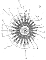
- a machine 1 comprises a turntable structure 2 angularly indexable around a vertical axis Z and comprising a plurality of support arms 4 radially arranged and reciprocally staggered by an angle of 15°.
- a series of five operating units 12 are arranged in sequence, each one of which comprises a heating station 6 of containers 7 supported at the end of each arm 4, a printing station 8 of the containers 7 and a drying station 10 of the printed containers.
- the different operating units 12 can each be used to print a colour, so that the overall pattern printed on the containers 7 may comprise five colours. Furthermore, the different operating units can be arranged to print different faces of the same container 7, so that up to five different faces of the same container 7 can be printed.
- the containers 7 are taken one after the other by the arms 4 near to the stations 6, 8, 10 of the different operating units 12 as the arms 4 advance by an angle of 15° in the direction indicated by the arrow R.
- one or more loading stations 14 are provided arranged for receiving, manually or automatically, on the arms 4 containers 7 to be printed.
- one or more unloading stations 16 are provided arranged for removing, manually or automatically, from the arms 4 the already printed containers 7.
- a filling station 18 of the printed containers 7 can be provided upstream of the first unloading station 16 .
- the arms 4 comprise bottom parts 26 connected to a central hub 31 and top parts 28 the heights of which can be adjusted with respect to the hub 31.
- the bottom parts 26 terminate in a bottom cradle means 32 suitable for receiving a bottom end of the containers 7, 7a and which can be rotationally actuated by means of a respective motor that is not shown.
- the top parts can be actuated by means of operating cylinders 34 in such a way as to be able to engage and disengage with a tip 36 with which said top parts 36 are provided a the end facing the containers 7, 7a, a neck portion of the containers 7, 7a.
- each heating station 6 of the containers to be printed comprises heating means 15 such as to modify the molecular structure of the containers 7, if the container 7 are made of plastic material, and prepare the container 7 to receive printing means such as ink or glaze in the successive printing station 8 without the latter being subsequently able to become detached from the container 7.
- heating means 15 such as to modify the molecular structure of the containers 7, if the container 7 are made of plastic material, and prepare the container 7 to receive printing means such as ink or glaze in the successive printing station 8 without the latter being subsequently able to become detached from the container 7.
- Each printing station 8 comprises a printing unit 17 provided with an ink-jet printing head 19 arranged to direct jets of ink 30 (Figure 5) onto an external surface 3 of the containers 7 by means of a plurality of nozzles 24.
- the printing unit 17 is provided with moving means 23 arranged, as will be disclosed below in greater detail, to move the printing head 19 in such a way that the jets of ink 30 are substantially perpendicular to the surface 3 during the printing operations.
- Each drying station 10 comprises drying means 20, e.g. a UV-lamp drying means arranged to dry the ink distributed on the external surface 3 of the container 7 in the printing station 8 arranged immediately upstream.
- drying means 20 e.g. a UV-lamp drying means arranged to dry the ink distributed on the external surface 3 of the container 7 in the printing station 8 arranged immediately upstream.
- a container 7a has a cylindrical external surface 3 at least part of the circumference extension of which has to be printed, the container 7a is actuated to rotate around its own vertical longitudinal axis in a direction indicated by the arrow R2 whereas the printing head 19 is kept in a fixed position.
- the heating means 15 that is part of the heating station 6 can be fitted on a slide mounted on a bench of the machine 1, the slide can be actuated to run in a radial direction to enable registration of the position of the heating means with respect to the external surface 3 of the containers 7, 7a to be printed.
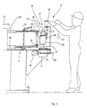
- a printing unit 17 comprises moving means 23 suitable for moving the printing head 19.
- the moving means 23 comprises a slide 44 that can be radially actuated by means of a motor 48 and a respective adjusting screw 50 along a radial direction indicated by the arrow F1, to which a further motor 40 and a further adjusting screw 42 are joined that are arranged to actuate the printing head 19 along a vertical direction indicated by the arrow F2.
- the moving means 23 finally comprises a yet further motor 38 arranged to rotate the printing head 19 around an X-axis.
- the moving means 23 make the printing head 19 perform a rotational translation movement in such a way that the latter can be maintained at a preset distance from the container 7, 7a during the printing operations.
- the moving means 23 furthermore enables the printing head 19 to expel the ink jets 30 in a manner that is substantially perpendicular to the surface 3 of the containers 7, 7a, which ensures high print quality.
- the drying means 20 of a drying station 10, like the heating means 14 and the printing head 19, are supported on a radial slide that is actuated towards and away from the containers 7, 7a.
- the machine 1 may function according to two distinct cycles: a continuous cycle and a indexing cycle.
- the turntable 2 moves continuously around the axis Z, the container 7 is locked on the cradle 32 whilst the moving means 23 moves the printing head 19 to enable the latter to transfer the ink to the external surface 3 of the container 7.
- the moving means 23 is controlled by an electronic command and control unit that is not shown in such a way that the printing head 19 moves in such a way as to follow the profile of the container 7.
- the machine 1 is provided with profile-detecting means, which is also not shown, that detects the profile of a container 7 and provides indications regarding the profile detected to the electronic command and control unit.
- the profile-detecting means comprises a proximity sensor associated to the moving means 23 and suitable for detecting the distance between the printing head 19 and the container 7.
- the profile-detecting means may comprise a mechanical probe arranged upstream of the printing unit 17.
- the moving means 23 actuates the printing head 19 to rotate as indicated by the arrow R1 and to simultaneously translate along the radial direction indicated by the arrow F1 - and possibly along the vertical direction indicated by the arrow F2 - to keep the printing head 19 pointing towards the surface 3 and at a preset distance from the container 7.
- the turntable 2 is indexed in the direction of arrow R to stop the container 7a at the printing station 8 where the container is actuated to rotate around its own longitudinal axis in the direction R2 whilst the jets of ink 30 expelled from the printing head 19, which is kept in a stationary position, are deposited on the surface 3.
Abstract
Description
- The invention concerns a system for printing on the external surface of items, in particular containers in general, for example bottles, or flasks made of glass, plastic material or other materials.
- The state of the art comprises silkscreen-printing machines for decorating containers provided with a flat screen underneath which the containers to be decorated are brought in sequence.
- In the case of containers having a curved lateral surface, both the containers and the screen are supported by organs that are able to move each container along a path corresponding to part of the extension of the lateral surface of the container while the container is kept tangent to the screen, in such a way as to enable the doctor that slide on the opposite side of the screen to progressively transfer the ink onto said lateral surface through open meshes of the screen that define a desired pattern to be printed.
- Moreover the above silkscreen printing machines are mechanically very complex and therefore expensive; furthermore, their setting up is very problematic and requires rather a long time of execution and the use of highly specialised labour; furthermore, in the event of faults, - because of their complexity - they are rather difficult to repair.
- EP 1147892 discloses a machine for printing on containers provided with a plurality of printing stations each one of which is equipped with a roller whose longitudinal axis is parallel to a longitudinal axis of a container to be printed.
- Each of said rollers is rotationally actuated around said longitudinal axis and is positioned in such a way as to face a lateral surface that has to be printed.
- Each roller is externally provided with a plurality of small cavities suitable for receiving an ink or glaze that has to be transferred onto the container.
- The ink is introduced into said cavities by means of a doctor blade that is kept adjacent to an external generatrix of the printing roller to remove the excess amount of ink poured in a zone immediately upstream of the doctor blade with respect to the rotation direction of the printing roller.
- During operation, when the containers are in contact with each printing roller, the ink contained in the cavities is deposited on the lateral surface of said containers, which are thereby decorated.
- The machine furthermore comprises a plurality of heating stations and a plurality of drying stations arranged in such a way that each of said printing stations is placed between a respective heating station and a respective drying station.
- During operation, the containers, before reaching each printing station, are advanced through a heating station wherein they are set up to receive the ink.
- Subsequently, once printing has been completed, each container is made to advance through a drying station in which the ink is dried so as to adhere permanently to the container.
- The machine disclosed above, although it enables excellent results to be obtained in printing on containers having a smooth external surface, is not as effective in printing on containers provided with a rough surface.
- This is due to the fact that in the machine disclosed above printing is achieved through contact between the smooth surface of the rollers and the surface of the containers.
- If the surface of the containers is corrugated, there is not perfect coupling between the surface of the rollers and the surface of the containers, with consequent imprecise printing.
- In fact, the surfaces of the containers may have zones in which there are small hollows, in this case said zones do not come into contact with the roller surfaces and are therefore lacking in ink.
- A further drawback occurs if containers have to be printed that have a bulging lateral surface, or comprising portions of spherical surface, in this case, even if the rollers are partially deformable to adapt to the shape of said surface, splashes and imprecision in the transfer of ink may occur.
- Machines for printing on containers are also known that have an ink-jet printing head and which are suitable for reproducing an inscription on a surface of a container, or a pattern in general.
- Such machines have a conveying line, along which the items are moved for interacting with said printing head, which is maintained in a stationary configuration during the operations of transfer of the ink.
- Said machines are able to print, with qualitatively acceptable results, only containers delimited by flat surfaces facing the printing head.
- Furthermore, said machines are unable to print complicated ornamental patterns, or complex inscriptions, but only groups of a few characters such as for example, packaging dates, numbers indicating the production batch and expiry dates.
- An object of the invention is to improve the systems for printing on items, in particular printing on containers in general.
- Another object is to obtain a system suitable for printing on items delimited by walls having any type of profile.
- A further object is to obtain a system that enables printing on items having any surface finish.
- A still further object of the invention is to obtain a system for printing captions or ornamental patterns of significant complexity on items.
- In a first aspect of the invention, a machine for printing on items is provided, comprising a printing unit provided with a printing head arranged to transfer at least one jet of printing means onto an external surface of said items, characterised in that said printing unit comprises moving means arranged to keep said at least one jet substantially perpendicular to said surface during said printing.
- In a preferred embodiment, the moving means is so configured as to move the printing head with respect to the containers to be printed.
- In a further preferred embodiment, the moving means is so configured as to keep the printing head and the surface to be printed at a substantially constant distance.
- Advantageously, said printing head comprises an ink-jet . printing head.
- Owing to this aspect of the invention an apparatus can be obtained that is suitable for printing on items having any profile and any surface finish.
- Providing an ink-jet printing head, in fact, enables contact between the printing head and an item to be printed to be avoided, thereby reducing the possibility of imprecision generated by surface roughness of the latter.
- Furthermore, providing moving means that enables the printing head to shift to keep itself at a constant preset distance from the item to be printed for the entire duration of printing operations enables printing on items delimited by surfaces having any extension.
- This furthermore enables printing of considerable complexity to be obtained with qualitatively highly satisfactory results.
- In another preferred embodiment, the machine furthermore comprises profile-detecting means suitable for detecting the profile of the surface of the item that has to be printed.
- Advantageously, said profile-detecting means comprises distance-sensor means associated with the printing head and suitable for detecting the distance between the printing head and the items to be printed.
- Also advantageously, said detecting means comprises, as an alternative to said sensor, mechanical probe means.
- In a further preferred embodiment, the machine furthermore comprises an electronic command and control unit arranged to command both the expulsion of the ink and the moving of the printing head.
- Advantageously, the electronic command and control unit communicates with the profile-detecting means.
- In a second aspect of this invention a method for printing on items is provided, comprising transferring at least one jet of printing means onto an external surface of said items, characterised in that, during said transferring, there is provided keeping at least said one said jet substantially perpendicular to said surface.
- In a preferred embodiment said keeping comprises moving said at least one jet with respect to said surface.
- In another preferred embodiment, said transferring comprises expelling said jet from a printing head.
- In a further preferred embodiment, during said transferring, there is provided keeping the printing head and said surface at a substantially constant distance.
- In a still further preferred embodiment, before said transferring, there is provided detecting the profile of said surface.
- Owing to this aspect of the invention, a method is provided that enables items to be printed that have external surfaces that extend along curved profiles with rather satisfying quality results.
- Such method furthermore enables ornamental patterns or inscriptions to be obtained on the surfaces of the containers to be printed that are of significant complexity but are nevertheless clearly defined.
- The invention will be better understood and carried out with reference to the attached drawings, which illustrate some exemplifying and not limiting embodiments thereof, in which:
- Figure 1 is a schematic plan view of a machine for printing on containers;
- Figure 2 is a partial and enlarged schematic plan view of the machine in Figure 1, showing a heating station of containers, a station of containers and a drying station of printed containers, during the printing of a container having a partially elliptic external surface;
- Figure 3 is a view like that of Figure 2 that shows the machine during printing of a container having a cylindrical external surface;
- Figure 4 is a schematic and enlarged cross-section taken along the plane IV-IV of Figure 1;
- Figure 5 is a schematic plan view of a printing head of the machine according to the invention, shown in two successive work configurations.
-
- As shown in Figures 1 and 4, a
machine 1 comprises a turntable structure 2 angularly indexable around a vertical axis Z and comprising a plurality ofsupport arms 4 radially arranged and reciprocally staggered by an angle of 15°. - At the periphery of the turntable structure 2, at the stop zones of the end of each
arm 4, a series of fiveoperating units 12 are arranged in sequence, each one of which comprises aheating station 6 ofcontainers 7 supported at the end of eacharm 4, aprinting station 8 of thecontainers 7 and adrying station 10 of the printed containers. - The
different operating units 12 can each be used to print a colour, so that the overall pattern printed on thecontainers 7 may comprise five colours. Furthermore, the different operating units can be arranged to print different faces of thesame container 7, so that up to five different faces of thesame container 7 can be printed. - The
containers 7 are taken one after the other by thearms 4 near to thestations different operating units 12 as thearms 4 advance by an angle of 15° in the direction indicated by the arrow R. - Upstream of the
first operating unit 12 one ormore loading stations 14 are provided arranged for receiving, manually or automatically, on thearms 4containers 7 to be printed. - Downstream of the
last operating unit 12 one ormore unloading stations 16 are provided arranged for removing, manually or automatically, from thearms 4 the already printedcontainers 7. - Upstream of the first unloading station 16 a
filling station 18 of the printedcontainers 7 can be provided. - The
arms 4 comprisebottom parts 26 connected to acentral hub 31 andtop parts 28 the heights of which can be adjusted with respect to thehub 31. Thebottom parts 26 terminate in a bottom cradle means 32 suitable for receiving a bottom end of thecontainers - The top parts can be actuated by means of
operating cylinders 34 in such a way as to be able to engage and disengage with atip 36 with which saidtop parts 36 are provided a the end facing thecontainers containers - As shown in Figures 2 and 3, each
heating station 6 of the containers to be printed comprises heating means 15 such as to modify the molecular structure of thecontainers 7, if thecontainer 7 are made of plastic material, and prepare thecontainer 7 to receive printing means such as ink or glaze in thesuccessive printing station 8 without the latter being subsequently able to become detached from thecontainer 7. - Each
printing station 8 comprises aprinting unit 17 provided with an ink-jet printing head 19 arranged to direct jets of ink 30 (Figure 5) onto anexternal surface 3 of thecontainers 7 by means of a plurality ofnozzles 24. - The
printing unit 17 is provided with movingmeans 23 arranged, as will be disclosed below in greater detail, to move theprinting head 19 in such a way that the jets ofink 30 are substantially perpendicular to thesurface 3 during the printing operations. - Each drying
station 10 comprises drying means 20, e.g. a UV-lamp drying means arranged to dry the ink distributed on theexternal surface 3 of thecontainer 7 in theprinting station 8 arranged immediately upstream. - It should be observed that in the particular case of the
containers 7 having anexternal surface 3 comprising an oval or elliptic portion 11 thecontainers 7 are not subject to rotation around their respective longitudinal vertical axis, as will be better explained below. - On the other hand, as illustrated with particular reference to Figure 3, if a
container 7a has a cylindricalexternal surface 3 at least part of the circumference extension of which has to be printed, thecontainer 7a is actuated to rotate around its own vertical longitudinal axis in a direction indicated by the arrow R2 whereas theprinting head 19 is kept in a fixed position. - The heating means 15 that is part of the
heating station 6 can be fitted on a slide mounted on a bench of themachine 1, the slide can be actuated to run in a radial direction to enable registration of the position of the heating means with respect to theexternal surface 3 of thecontainers - With reference to Figure 4, a
printing unit 17 comprises moving means 23 suitable for moving theprinting head 19. - The moving means 23 comprises a
slide 44 that can be radially actuated by means of amotor 48 and a respective adjustingscrew 50 along a radial direction indicated by the arrow F1, to which afurther motor 40 and a further adjustingscrew 42 are joined that are arranged to actuate theprinting head 19 along a vertical direction indicated by the arrow F2. - The moving means 23 finally comprises a yet further motor 38 arranged to rotate the
printing head 19 around an X-axis. - The moving means 23 make the
printing head 19 perform a rotational translation movement in such a way that the latter can be maintained at a preset distance from thecontainer - The moving means 23 furthermore enables the
printing head 19 to expel theink jets 30 in a manner that is substantially perpendicular to thesurface 3 of thecontainers - The drying means 20 of a drying
station 10, like the heating means 14 and theprinting head 19, are supported on a radial slide that is actuated towards and away from thecontainers - The
machine 1 may function according to two distinct cycles: a continuous cycle and a indexing cycle. - During operation in the continuous cycle, which is suitable for containers that are not symmetrical with respect to a respective vertically arranged longitudinal axis, the turntable 2 moves continuously around the axis Z, the
container 7 is locked on thecradle 32 whilst the moving means 23 moves theprinting head 19 to enable the latter to transfer the ink to theexternal surface 3 of thecontainer 7. - The moving means 23 is controlled by an electronic command and control unit that is not shown in such a way that the
printing head 19 moves in such a way as to follow the profile of thecontainer 7. - For this purpose, the
machine 1 is provided with profile-detecting means, which is also not shown, that detects the profile of acontainer 7 and provides indications regarding the profile detected to the electronic command and control unit. - The profile-detecting means comprises a proximity sensor associated to the moving means 23 and suitable for detecting the distance between the
printing head 19 and thecontainer 7. - Alternatively, the profile-detecting means may comprise a mechanical probe arranged upstream of the
printing unit 17. - As shown in Figure 5, during operation of the
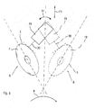
machine 1, whilst onecontainer 7 rotates in the direction indicated by the arrow R to change from a work position indicated with A to a further work position indicated with B, the moving means 23 actuates theprinting head 19 to rotate as indicated by the arrow R1 and to simultaneously translate along the radial direction indicated by the arrow F1 - and possibly along the vertical direction indicated by the arrow F2 - to keep theprinting head 19 pointing towards thesurface 3 and at a preset distance from thecontainer 7. - During operation in the indexing cycle, which is suitable for containers that are symmetrical in relation to a relative vertically arranged longitudinal axis, the turntable 2 is indexed in the direction of arrow R to stop the
container 7a at theprinting station 8 where the container is actuated to rotate around its own longitudinal axis in the direction R2 whilst the jets ofink 30 expelled from theprinting head 19, which is kept in a stationary position, are deposited on thesurface 3.
Claims (36)
- Machine for printing on items (7; 7a), comprising a printing unit (17) provided with a printing head (19) arranged to transfer at least one jet (30) of printing means onto an external surface (3) of said items (7; 7a), characterised in that said printing unit (17) comprises moving means (23) arranged to maintain said at least one jet (30) substantially perpendicular to said surface (30) during said printing.
- Machine according to claim 1, wherein said moving means (23) is so configured as to move said printing head (19) with respect to said containers (7; 7a).
- Machine according to claim 1, or 2, wherein said moving means (23) is so configured as to keep said printing head (19) at a preset distance from said surface (3).
- Machine according to any one of the preceding claims, wherein said moving means (23) comprises translation actuating means (40, 42, 44, 48, 50) arranged to vary the distance of said printing head (19) and of said item (7; 7a) from one another.
- Machine according to any one of the preceding claims, wherein said moving means (23) comprises rotation actuating means (38) arranged to rotate said printing head (19) with respect to said item (7; 7a).
- Machine according to claim 4, or according to claim 5 as appended to claim 4, wherein said translation actuating means comprises slide means (44) arranged to transfer said printing head (19) towards and/or away from said containers (7; 7a).
- Machine according to claim 6, wherein said slide means is controlled by motor means (48) actuating respective worm-screw means (50).
- Machine according to claim 6, or 7, wherein said translation actuating means comprises further motor means (40) fixed to said slide means (44) and actuating further worm-screw means (42) for transferring said printing head (19) along a direction (F1) substantially parallel to a longitudinal axis of said containers (7; 7a).
- Machine according to claim 8 as claim 6 is appended to claim 5, wherein said further worm-screw means (42) is arranged to move said rotating actuating means (38).
- Machine according to any one of the preceding claims, and further comprising profile-detecting means arranged to detect the profile of said surface (3).
- Machine according to claim 10, wherein said profile-detecting means comprises proximity-sensor means arranged to detect the distance of said printing head (19) from said containers (7; 7a).
- Machine according to claim 11, wherein said sensor means is associated with said moving means (23).
- Machine according to claim 11, wherein said profile-detecting means comprises mechanical probe means.
- Machine according to claim 13, wherein said mechanical probe means is provided upstream of said printing unit (17).
- Machine according to any one of the preceding claims, and furthermore comprising support means (32, 36) arranged to grip said containers (7; 7a).
- Machine according to claim 15, wherein said support means (32, 36) is fixed to a free end of arm means (4) that extends from a central hub (30) of said machine (1) and are rotatable around a vertical axis (Z).
- Machine according to claim 16, wherein said arm means (4) comprises a lower part (26) and said support means comprises lower support means (32) suitable for receiving a lower bottom part of each of said containers (7, 7a).
- Machine according to claim 16, or 17, wherein said arm means (4) comprises an upper part (28) and said support means comprises tip means (36) suitable for being inserted in a mouth part of said containers (7, 7a).
- Machine according to any one of the preceding claims, and further comprising actuating means for rotating said containers (7, 7a) around a longitudinal axis thereof.
- Machine according to any one of the preceding claims, and further comprising, upstream of said printing unit (17), a heating unit (6) of said containers (7, 7a).
- Machine according to any one of the preceding claims, and further comprising a drying unit (10) arranged to dry the printed containers (7, 7a).
- Machine according to claim 20, or 21, wherein said heating unit (6), or said drying unit (10), are movable on a respective movable slide in a radial direction.
- Machine according to any one of claims 16 to 18, or according to any one of claims 19 to 22 as appended to any one of claims 16 to 18, and comprising in succession, along a rotation direction (R) of said arms (4) at least: a heating unit (6), a printing unit (17) and a drying unit (10).
- Machine according to any one of the preceding claims, and furthermore comprising a loading station (14) of the containers (7, 7a) to be printed.
- Machine according to any one of the preceding claims, and further comprising an unloading station (16) of the printed containers (7, 7a).
- Machine according to claim 25, wherein upstream of said unloading station (16) a filling station (18) of the printed containers (7, 7a) is provided.
- Machine according to any one of the preceding claims, wherein said containers (7; 7a) comprise a portion of external surface (3) having a curved extension.
- Method for printing on items (7; 7a), comprising transferring at least one jet (30) of printing means onto an external surface (3) of said items (7; 7a), characterised in that during said transferring there is provided keeping said at least one jet (30) substantially perpendicular to said surface.
- Method according to claim 28, wherein said keeping comprises moving said at least one jet (30) with respect to said containers (7; 7a).
- Method according to claim 29, wherein said transferring comprises expelling said at least one jet (30) from a printing head (19).
- Method according to claim 30, wherein said moving comprises keeping said printing head (19) and said surface (3) at a substantially constant distance.
- Method according to any one of claims 28 to 31, wherein before said transferring there is provided detecting the profile of said surface (3).
- Method according to any one of claims 28 to 32, wherein during said transferring there is provided moving said containers (7, 7a) along a preset trajectory.
- Method according to claim 33, wherein said containers (7; 7a) are indexed along said preset trajectory.
- Method according to claim 33, or 34, wherein said preset trajectory is a circular trajectory.
- Method according to any one of claims 28 to 35, wherein said transferring comprises transferring said at least one jet (30) onto containers (7; 7a) comprising a portion of external surface (3) having a curved extension.
Applications Claiming Priority (2)
| Application Number | Priority Date | Filing Date | Title |
|---|---|---|---|
| ITMO20020369 | 2002-12-30 | ||
| IT000369A ITMO20020369A1 (en) | 2002-12-30 | 2002-12-30 | SYSTEM FOR PRINTING OBJECTS. |
Publications (1)
| Publication Number | Publication Date |
|---|---|
| EP1435296A1 true EP1435296A1 (en) | 2004-07-07 |
Family
ID=27677303
Family Applications (1)
| Application Number | Title | Priority Date | Filing Date |
|---|---|---|---|
| EP03029720A Withdrawn EP1435296A1 (en) | 2002-12-30 | 2003-12-23 | System for printing on items |
Country Status (2)
| Country | Link |
|---|---|
| EP (1) | EP1435296A1 (en) |
| IT (1) | ITMO20020369A1 (en) |
Cited By (23)
| Publication number | Priority date | Publication date | Assignee | Title |
|---|---|---|---|---|
| EP1636032A2 (en) | 2003-06-05 | 2006-03-22 | Stolle Machinery Company LLC | Digital can decorating apparatus |
| WO2006065506A1 (en) * | 2004-12-10 | 2006-06-22 | Eastman Kodak Company | In-line fabrication of curved surface transistors |
| DE102006001223A1 (en) * | 2006-01-10 | 2007-07-12 | Khs Ag | Apparatus for printing on bottles or similar containers |
| DE102006019441A1 (en) * | 2006-04-24 | 2007-10-25 | Khs Ag | Method and device for printing on containers |
| EP1892108A1 (en) * | 2006-08-25 | 2008-02-27 | Homag Holzbearbeitungssysteme AG | Device for printing on workpiece |
| DE102007036752A1 (en) * | 2007-08-03 | 2009-02-05 | Khs Ag | Machine for printing on e.g. bottles has ink-jet printing heads mounted on turntable, around which containers pass during printing stage, individual heads being able to be withdrawn from printing position and replaced by different head |
| DE102007050490A1 (en) * | 2007-10-19 | 2009-04-23 | Khs Ag | Device for printing containers, has printing group provided with printing heads operating according to ink jet printing principle |
| US7914098B2 (en) | 2006-11-07 | 2011-03-29 | Homag Holzbearbeitungssysteme Ag | Device for patterning workpieces |
| US8038236B2 (en) | 2006-08-25 | 2011-10-18 | Homag Holzbearbeitungssysteme Ag | Device for patterning workpieces |
| US8104887B2 (en) | 2007-03-27 | 2012-01-31 | Homag Holzbearbeitungssysteme Ag | Method for imprinting a three-dimensional article |
| US8366260B2 (en) | 2006-03-08 | 2013-02-05 | Homag Holzbearbeitungssysteme Ag | Process and apparatus for the printing of panel-shaped workpieces |
| EP2591917A1 (en) | 2011-11-09 | 2013-05-15 | Krones AG | Method and device for ink-jet printing on curved container surfaces |
| US8650835B2 (en) | 2011-05-26 | 2014-02-18 | Presto Absorbent Products, Inc. | Indicia-applying method and apparatus |
| EP2832546A1 (en) * | 2013-07-31 | 2015-02-04 | Krones AG | Printing machine with print head control |
| US9132664B2 (en) | 2007-08-03 | 2015-09-15 | Khs Gmbh | Device and method for adding information on the outer surface of articles, such as containers in a container filling plant |
| US9272815B2 (en) | 2006-05-09 | 2016-03-01 | Plastipak Packaging, Inc. | Digital printing plastic container |
| US9302506B2 (en) | 2008-06-24 | 2016-04-05 | Plastipak Packaging, Inc. | Apparatus and method for printing on articles having a non-planar surface |
| WO2016074895A1 (en) * | 2014-11-10 | 2016-05-19 | Khs Gmbh | Printing device and method for printing containers |
| EP2479037B1 (en) | 2011-01-25 | 2017-08-30 | Krones AG | Method and device for printing containers |
| DE202016107234U1 (en) * | 2016-12-21 | 2018-03-22 | Krones Ag | Labeling machine with data unit |
| US10105900B2 (en) | 2013-08-14 | 2018-10-23 | Homag Holzbearbeitungssysteme Gmbh | Coating unit |
| US10166781B2 (en) | 2007-10-19 | 2019-01-01 | Khs Gmbh | Bottling plant with an information-adding station configured to add information on the outer surface of a bottle or container |
| EP2783852B1 (en) * | 2013-03-25 | 2020-07-29 | Krones AG | Printing apparatus for printing on containers |
Citations (5)
| Publication number | Priority date | Publication date | Assignee | Title |
|---|---|---|---|---|
| GB2180195A (en) * | 1985-09-04 | 1987-03-25 | Waterford Crystal Ltd | Using ink drop devices to mark out work |
| US5815282A (en) * | 1992-06-24 | 1998-09-29 | Sony Corporation | Cassette having color-printed recessed and conveyed surfaces |
| US20010003871A1 (en) * | 1998-01-27 | 2001-06-21 | Eastman Kodak Company | Apparatus and method for marking multiple colors on a contoured surface having a complex topography |
| EP1147892A2 (en) | 2000-03-21 | 2001-10-24 | Tecno-Italia S.R.L. | Machine and method for printing containers |
| US20020024544A1 (en) * | 2000-08-30 | 2002-02-28 | Codos Richard N. | Method and apparatus for printing on rigid panels and other contoured or textured surfaces |
-
2002
- 2002-12-30 IT IT000369A patent/ITMO20020369A1/en unknown
-
2003
- 2003-12-23 EP EP03029720A patent/EP1435296A1/en not_active Withdrawn
Patent Citations (5)
| Publication number | Priority date | Publication date | Assignee | Title |
|---|---|---|---|---|
| GB2180195A (en) * | 1985-09-04 | 1987-03-25 | Waterford Crystal Ltd | Using ink drop devices to mark out work |
| US5815282A (en) * | 1992-06-24 | 1998-09-29 | Sony Corporation | Cassette having color-printed recessed and conveyed surfaces |
| US20010003871A1 (en) * | 1998-01-27 | 2001-06-21 | Eastman Kodak Company | Apparatus and method for marking multiple colors on a contoured surface having a complex topography |
| EP1147892A2 (en) | 2000-03-21 | 2001-10-24 | Tecno-Italia S.R.L. | Machine and method for printing containers |
| US20020024544A1 (en) * | 2000-08-30 | 2002-02-28 | Codos Richard N. | Method and apparatus for printing on rigid panels and other contoured or textured surfaces |
Cited By (32)
| Publication number | Priority date | Publication date | Assignee | Title |
|---|---|---|---|---|
| EP1636032A2 (en) | 2003-06-05 | 2006-03-22 | Stolle Machinery Company LLC | Digital can decorating apparatus |
| EP1636032B1 (en) | 2003-06-05 | 2020-11-25 | Ball Beverage Packaging Europe Limited | Digital can decorating apparatus |
| WO2006065506A1 (en) * | 2004-12-10 | 2006-06-22 | Eastman Kodak Company | In-line fabrication of curved surface transistors |
| US9221275B2 (en) | 2006-01-10 | 2015-12-29 | Khs Gmbh | Method of printing a pictorial image onto the circumferential outer surface of beverage bottles and filling beverage bottles in a bottling plant for filling bottles with a liquid beverage filling material in rotary filling machinery and apparatus therefor |
| DE102006001223A1 (en) * | 2006-01-10 | 2007-07-12 | Khs Ag | Apparatus for printing on bottles or similar containers |
| US8366260B2 (en) | 2006-03-08 | 2013-02-05 | Homag Holzbearbeitungssysteme Ag | Process and apparatus for the printing of panel-shaped workpieces |
| US7997201B2 (en) | 2006-04-24 | 2011-08-16 | Khs Ag | Method and device for labeling containers |
| DE102006019441B4 (en) * | 2006-04-24 | 2013-06-20 | Khs Gmbh | Method and device for printing on containers |
| DE102006019441A1 (en) * | 2006-04-24 | 2007-10-25 | Khs Ag | Method and device for printing on containers |
| US9272815B2 (en) | 2006-05-09 | 2016-03-01 | Plastipak Packaging, Inc. | Digital printing plastic container |
| US8038236B2 (en) | 2006-08-25 | 2011-10-18 | Homag Holzbearbeitungssysteme Ag | Device for patterning workpieces |
| EP1892108A1 (en) * | 2006-08-25 | 2008-02-27 | Homag Holzbearbeitungssysteme AG | Device for printing on workpiece |
| US7914098B2 (en) | 2006-11-07 | 2011-03-29 | Homag Holzbearbeitungssysteme Ag | Device for patterning workpieces |
| US8104887B2 (en) | 2007-03-27 | 2012-01-31 | Homag Holzbearbeitungssysteme Ag | Method for imprinting a three-dimensional article |
| DE102007036752A1 (en) * | 2007-08-03 | 2009-02-05 | Khs Ag | Machine for printing on e.g. bottles has ink-jet printing heads mounted on turntable, around which containers pass during printing stage, individual heads being able to be withdrawn from printing position and replaced by different head |
| US9132664B2 (en) | 2007-08-03 | 2015-09-15 | Khs Gmbh | Device and method for adding information on the outer surface of articles, such as containers in a container filling plant |
| DE102007050490A1 (en) * | 2007-10-19 | 2009-04-23 | Khs Ag | Device for printing containers, has printing group provided with printing heads operating according to ink jet printing principle |
| US10166781B2 (en) | 2007-10-19 | 2019-01-01 | Khs Gmbh | Bottling plant with an information-adding station configured to add information on the outer surface of a bottle or container |
| US9302506B2 (en) | 2008-06-24 | 2016-04-05 | Plastipak Packaging, Inc. | Apparatus and method for printing on articles having a non-planar surface |
| EP2479037B1 (en) | 2011-01-25 | 2017-08-30 | Krones AG | Method and device for printing containers |
| EP2479037B2 (en) † | 2011-01-25 | 2021-01-06 | Krones AG | Method and device for printing containers |
| US8650835B2 (en) | 2011-05-26 | 2014-02-18 | Presto Absorbent Products, Inc. | Indicia-applying method and apparatus |
| DE102011086015A1 (en) | 2011-11-09 | 2013-05-16 | Krones Aktiengesellschaft | Method and apparatus for ink jet printing on curved object surfaces |
| EP2591917A1 (en) | 2011-11-09 | 2013-05-15 | Krones AG | Method and device for ink-jet printing on curved container surfaces |
| EP2783852B1 (en) * | 2013-03-25 | 2020-07-29 | Krones AG | Printing apparatus for printing on containers |
| DE102013214980A1 (en) * | 2013-07-31 | 2015-02-05 | Krones Ag | Printing machine with printhead control |
| EP2832546A1 (en) * | 2013-07-31 | 2015-02-04 | Krones AG | Printing machine with print head control |
| US9327492B2 (en) | 2013-07-31 | 2016-05-03 | Krones Ag | Printing machine with print head control |
| US10105900B2 (en) | 2013-08-14 | 2018-10-23 | Homag Holzbearbeitungssysteme Gmbh | Coating unit |
| WO2016074895A1 (en) * | 2014-11-10 | 2016-05-19 | Khs Gmbh | Printing device and method for printing containers |
| US10286684B2 (en) | 2014-11-10 | 2019-05-14 | Khs Gmbh | Printing device and method for printing containers |
| DE202016107234U1 (en) * | 2016-12-21 | 2018-03-22 | Krones Ag | Labeling machine with data unit |
Also Published As
| Publication number | Publication date |
|---|---|
| ITMO20020369A1 (en) | 2004-06-30 |
| ITMO20020369A0 (en) | 2002-12-30 |
Similar Documents
| Publication | Publication Date | Title |
|---|---|---|
| EP1435296A1 (en) | System for printing on items | |
| CA2536581C (en) | Digital can decorating apparatus | |
| CA1277176C (en) | Process and apparatus for decorating a container | |
| US2721516A (en) | Work supporting and registering apparatus for bottle decorating machine | |
| JP4056561B2 (en) | Method and apparatus for decorating bottles or similar articles | |
| US20090251523A1 (en) | Method and device for decorating an uneven surface of a dimensionally stable object | |
| US9895876B2 (en) | Apparatus comprising a plurality of printing units for printing hollow elements | |
| AU615603B2 (en) | A process and a device for printing on articles by silk screening | |
| US6584895B1 (en) | Apparatus for printing on individual articles | |
| US3868902A (en) | Multi-station printing machine for ceramic ware | |
| US20170197403A1 (en) | Printing unit having a plate cylinder and plate changer | |
| US5771798A (en) | Can decorating apparatus | |
| WO1991001884A1 (en) | Combined ink laser printing of tablets | |
| US20210039381A1 (en) | Device for printing on hollow bodies | |
| US20190022998A1 (en) | Device for printing hollow bodies, and method for operating said device | |
| EP0535981B1 (en) | Apparatus to load workpieces | |
| US9833989B2 (en) | Device for printing on hollow bodies | |
| US11123976B2 (en) | Device for printing on hollow articles | |
| CN111225799A (en) | Container decorating apparatus and method | |
| WO2015010984A1 (en) | Apparatus for printing closure bodies of containers | |
| WO2022231637A1 (en) | Compact media decorator optimized for transparent and semi-transparent media | |
| US6223653B1 (en) | Screen printing apparatus | |
| EP1147892A2 (en) | Machine and method for printing containers | |
| CN110267814B (en) | Method for operating a device for printing hollow bodies | |
| EP1172039A1 (en) | Confectionery printing machine and method |
Legal Events
| Date | Code | Title | Description |
|---|---|---|---|
| PUAI | Public reference made under article 153(3) epc to a published international application that has entered the european phase |
Free format text: ORIGINAL CODE: 0009012 |
|
| AK | Designated contracting states |
Kind code of ref document: A1 Designated state(s): AT BE BG CH CY CZ DE DK EE ES FI FR GB GR HU IE IT LI LU MC NL PT RO SE SI SK TR |
|
| AX | Request for extension of the european patent |
Extension state: AL LT LV MK |
|
| 17P | Request for examination filed |
Effective date: 20041110 |
|
| AKX | Designation fees paid |
Designated state(s): AT BE BG CH CY CZ DE DK EE ES FI FR GB GR HU IE IT LI LU MC NL PT RO SE SI SK TR |
|
| 17Q | First examination report despatched |
Effective date: 20050301 |
|
| GRAP | Despatch of communication of intention to grant a patent |
Free format text: ORIGINAL CODE: EPIDOSNIGR1 |
|
| STAA | Information on the status of an ep patent application or granted ep patent |
Free format text: STATUS: THE APPLICATION IS DEEMED TO BE WITHDRAWN |
|
| 18D | Application deemed to be withdrawn |
Effective date: 20090722 |