EP1439399A2 - Procedure and apparatus for determining the condition of a vehicle battery - Google Patents
Procedure and apparatus for determining the condition of a vehicle battery Download PDFInfo
- Publication number
- EP1439399A2 EP1439399A2 EP03025647A EP03025647A EP1439399A2 EP 1439399 A2 EP1439399 A2 EP 1439399A2 EP 03025647 A EP03025647 A EP 03025647A EP 03025647 A EP03025647 A EP 03025647A EP 1439399 A2 EP1439399 A2 EP 1439399A2
- Authority
- EP
- European Patent Office
- Prior art keywords
- weighting factor
- voltage
- battery
- voltage threshold
- evaluation unit
- Prior art date
- Legal status (The legal status is an assumption and is not a legal conclusion. Google has not performed a legal analysis and makes no representation as to the accuracy of the status listed.)
- Withdrawn
Links
Images
Classifications
-
- G—PHYSICS
- G01—MEASURING; TESTING
- G01R—MEASURING ELECTRIC VARIABLES; MEASURING MAGNETIC VARIABLES
- G01R31/00—Arrangements for testing electric properties; Arrangements for locating electric faults; Arrangements for electrical testing characterised by what is being tested not provided for elsewhere
- G01R31/36—Arrangements for testing, measuring or monitoring the electrical condition of accumulators or electric batteries, e.g. capacity or state of charge [SoC]
- G01R31/367—Software therefor, e.g. for battery testing using modelling or look-up tables
-
- G—PHYSICS
- G01—MEASURING; TESTING
- G01R—MEASURING ELECTRIC VARIABLES; MEASURING MAGNETIC VARIABLES
- G01R31/00—Arrangements for testing electric properties; Arrangements for locating electric faults; Arrangements for electrical testing characterised by what is being tested not provided for elsewhere
- G01R31/36—Arrangements for testing, measuring or monitoring the electrical condition of accumulators or electric batteries, e.g. capacity or state of charge [SoC]
- G01R31/382—Arrangements for monitoring battery or accumulator variables, e.g. SoC
Definitions
- the invention relates to a method and a device to determine the condition of a vehicle battery.
- DE 198 45 562 Cl describes a method for the determination the wiring system state of a motor vehicle using the measurement of the battery voltage known. Doing so the battery voltage averaged over a longer period of time. A critical condition is recognized when a defined one Voltage threshold is undershot.
- a method with the features specified in claim 1 has the advantage of a more precise determination the condition of the vehicle battery.
- the condition of a vehicle battery can be temporary Events and long-term effects that are not taken into account to inaccurate or even false statements about would keep the condition of the vehicle battery in reasonable condition Way are taken into account.
- An example for a short-term event is an occurring load jump, which leads to a short-term dip in voltage leads.
- An example of a long-term effect is aging the vehicle battery.
- Another advantage of the invention is that the claimed method does not require complex recording of the Battery power needed.
- the weighting factor is according to that in the claim 3 specified relationship calculated. This can the accuracy of determining the condition of a vehicle battery by considering a variety of different Status information will be improved.
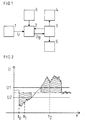
- FIG. 1 shows a block diagram of a device to determine the condition of a vehicle battery.
- the Figure 2 shows a sketch to illustrate the mode of operation a device according to a first embodiment for the invention.
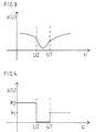
- Figure 3 shows one Sketch to illustrate how a Device according to a second embodiment for The invention.
- Figure 4 shows a sketch for illustration the mode of operation of a device a third embodiment for the invention.
- FIG. 1 shows a block diagram of a device for determining the state of a vehicle battery.
- This device has a voltmeter 1, which is provided for measuring the battery voltage.
- the output signals of the voltmeter 1 are fed to an evaluation unit 2 which, using the signals supplied to it by the voltmeter 1 and preferably using further signals at its output, provides a signal U B which describes the state of the vehicle battery.
- the further signals mentioned are also referred to below as status information.
- the signal U B is fed to the energy management 3 of the vehicle. Energy management 3 is intended to influence the energy supply and energy consumption available in the vehicle.
- the energy manager 3 initiates suitable countermeasures to improve the charge balance of the vehicle battery in order to ensure that the safety-relevant components of the vehicle continue to work.
- These safety-relevant components include, for example, an electro-hydraulic brake and the power steering of the vehicle.
- the suitable countermeasures are that the energy management 3 closes a switch 4 in order to connect an auxiliary battery. Additionally or alternatively, the energy management 3 also provides a further switching unit 5 with control signals by means of which, for the purpose of reducing the energy consumption, consumers of the vehicle which are not safety-relevant are switched off or at least their power consumption is reduced.
- non-safety-relevant consumers include, for example, the rear window heating of the vehicle and the seat heating.
- the further signals which the evaluation unit 2 preferably uses to determine the signal U B describing the state of the vehicle battery are made available to the evaluation unit 2, for example by an information transmitter 6 and / or the energy management 3. This is additional information available from the vehicle electrical system. This further information includes information about the temperature of the battery, information about the energy status of the vehicle, information about load jumps occurring in the vehicle electrical system, information about voltage dips that occur, information about the battery current and information about the quiescent voltage.
- the information mentioned is sent to the evaluation unit 2 via the vehicle's CAN bus. They can also be fed to the evaluation unit 2 directly from the respective information source or via other bus configurations.
- FIG. 2 shows a sketch to illustrate the functioning of a device according to a first exemplary embodiment of the invention.
- the battery voltage U measured by the voltmeter 1 is fed to the evaluation unit 2.
- the evaluation unit 2 has an integrator. This is started after every vehicle start, after an initialization has been carried out and a battery idle current evaluation has taken place. It calculates a voltage integral L (t), which provides information about the charge balance of the vehicle battery, according to the following relationship:
- U1 is a predetermined upper voltage threshold
- U2 a predetermined lower voltage threshold. This Voltage thresholds are dependent on the given application.
- the weighting factor a [U ( ⁇ )] has for measured voltage values, those below the lower voltage threshold U2, the value 1.
- the weighting factor a [U ( ⁇ )] has for measured voltage values, those above the upper voltage threshold U1, the value 1.
- the voltage integral L determined is compared in the evaluation unit 2 with a predetermined limit value G. If the determined voltage integral L falls below this limit value, then the evaluation unit 2 generates a state of charge signal U B , which signals the energy management 3 that the state of charge of the vehicle battery is insufficient. The energy management 3 then initiates measures to improve the charge balance. For example, a switch 4 is closed in order to connect an auxiliary battery. As an alternative or in addition to this, the energy management 3 can also generate control signals for the switching unit 5, as a result of which non-safety-relevant consumers of the vehicle are switched off or their power consumption is reduced.
- the auxiliary battery then remains switched off and the non-security consumers remain - if they are currently activated - in operation.
- FIG. 3 shows a sketch to illustrate the functioning of a device according to a second exemplary embodiment of the invention.
- the weighting factor a in this second exemplary embodiment also includes the dependence of the battery current on the current voltage. Consequently, in contrast to the first exemplary embodiment, the weighting factor a is no longer constant in sections, but has, for example, a profile as shown in FIG. 3.
- the information U B ascertained about the state of charge of the vehicle battery in energy management 3 is converted into control signals for switch 4 and / or switching unit 5.
- FIG. 4 shows a sketch to illustrate the Operation of a device according to a third embodiment for the invention.
- the variable is calibrated Weighting factor a by determining the state of charge using a quiescent voltage measurement.
- shape parameters that are included in the weighting factor come in, using correction data, which are obtained after a vehicle start, dynamic customized. This results in using that an integrated charge balance determination with time in the sense of self-adaptation always improved.
- a (U) a (k 1 , k 2 , ..., k n ; U).
- the weighting factor a is therefore dependent on the measured voltage U and a large number of preliminary factors k 1 , k 2 , ..., k n .
- FIG. 4 shows a simple exemplary embodiment, in which it is assumed that only two weight functions a 1 (U) and a 2 (U) are included in the calculation of the weighting factor, each of these weight functions being assigned a pre-factor k 1 and k 2 , respectively is.
- a (U) k 1 • a 1 (U) + k 2 • a 2 (U).
- any pre-factors k i can be used for the different weight functions in this exemplary embodiment.
- These pre-factors are variable and can be obtained through calibration and other available information such as status information from electrical energy management, information about load jumps and information about voltage dips in the vehicle electrical system. In practice, it makes sense to limit yourself to two or three weight functions and the associated pre-factors, depending on the application at hand.
- US, U1 and U2 are suitable voltage threshold values.
- the present invention is a Procedure that is easy and inexpensive to implement to determine the condition of a vehicle battery and the vehicle electrical system status is also available posed.
- the battery voltage is measured and fed to an evaluation unit. This is done an integration process in which a variable weighting factor is taken into account.
- the weighting factor can only depend on the measured battery voltage or also depending on other sizes his.
Abstract
Description
Die Erfindung betrifft ein Verfahren und eine Vorrichtung zur Ermittlung des Zustands einer Fahrzeugbatterie.The invention relates to a method and a device to determine the condition of a vehicle battery.
Zur Erhöhung der Verfügbarkeit in Bordnetzen mit hohem Anspruch an eine permanente Energieversorgung ist es bereits bekannt, Bordnetztopologien mit Hilfsbatterie einzusetzen. Über ein elektronisches Batteriemanagement wird der Zustand der Hauptbatterie vergleichsweise aufwendig ermittelt und abhängig von einem konstanten Schwellenwert die Hilfsbatterie zugeschaltet. Zur Ermittlung des Batteriezustandes wird in der Regel der Batteriestrom, die Batteriespannung und die Batterietemperatur verwendet.To increase the availability in on-board networks with high It is already a requirement for a permanent energy supply known to use on-board network topologies with auxiliary battery. Via an electronic battery management the condition of the main battery is comparatively complex determined and dependent on a constant threshold the auxiliary battery switched on. To determine the battery condition is usually the battery power that Battery voltage and battery temperature used.
Aus der DE 198 45 562 Cl ist ein Verfahren zur Ermittlung des Bordnetzzustandes eines Kraftfahrzeugs unter Verwendung der Messung der Batteriespannung bekannt. Dabei wird die Batteriespannung über einen längeren Zeitraum gemittelt. Ein kritischer Zustand wird erkannt, wenn eine definierte Spannungsschwelle unterschritten wird.DE 198 45 562 Cl describes a method for the determination the wiring system state of a motor vehicle using the measurement of the battery voltage known. Doing so the battery voltage averaged over a longer period of time. A critical condition is recognized when a defined one Voltage threshold is undershot.
Ein Verfahren mit den im Anspruch 1 angegebenen Merkmalen
hat demgegenüber den Vorteil einer genaueren Ermittlung
des Zustands der Fahrzeugbatterie. Durch die Berücksichtigung
eines variablen Gewichtungsfaktors bei der Ermittlung
des Zustands einer Fahrzeugbatterie können kurzzeitige
Ereignisse und Langzeiteffekte, die bei Nichtberücksichtigung
zu ungenauen oder gar falschen Aussagen über
den Zustand der Fahrzeugbatterie führen würden, in angemessener
Weise berücksichtigt werden. Ein Beispiel für
ein kurzzeitiges Ereignis ist ein auftretender Lastsprung,
der zu einem kurzfristigen Spannungseinbruch
führt. Ein Beispiel für einen Langzeiteffekt ist die Alterung
der Fahrzeugbatterie.A method with the features specified in
Weitere Vorteile der Erfindung bestehen darin, dass die Ermittlung des Zustands einer Fahrzeugbatterie in einfacher und kostenreduzierter Weise erfolgt.Further advantages of the invention are that the Determination of the state of a vehicle battery in simple and takes place at a reduced cost.
Aufgrund der genaueren Ermittlung des Zustands der Fahrzeugbatterie wird auch die Arbeitsweise eines elektrischen Energiemanagements, welchem die ermittelte Information über den Zustand der Fahrzeugbatterie zugeführt wird, verbessert. Weiterhin wird bei Bordnetztopologien, die eine Hilfsbatterie verwenden, die Zuschaltung der Hilfsbatterie optimiert.Due to the more accurate determination of the condition of the vehicle battery will also work like an electric Energy management, which the information determined supplied on the state of the vehicle battery will be improved. Furthermore, with on-board network topologies, who use an auxiliary battery, the connection of the Auxiliary battery optimized.
Ein weiterer Vorteil der Erfindung besteht darin, dass das beanspruchte Verfahren keine aufwendige Erfassung des Batteriestroms benötigt.Another advantage of the invention is that the claimed method does not require complex recording of the Battery power needed.
Vorzugsweise wird der Gewichtungsfaktor gemäß der im Anspruch 3 angegebenen Beziehung berechnet. Dadurch kann die Genauigkeit der Ermittlung des Zustands einer Fahrzeugbatterie durch Berücksichtigung einer Vielzahl verschiedener Statusinformationen verbessert werden.Preferably, the weighting factor is according to that in the claim 3 specified relationship calculated. This can the accuracy of determining the condition of a vehicle battery by considering a variety of different Status information will be improved.
Die Vorteile des im Anspruch 6 angegebenen Verfahrens bestehen
insbesondere in einer einfachen und preisgünstigen
Realisierung.The advantages of the method specified in
Weitere vorteilhafte Eigenschaften der Erfindung ergeben sich aus der nachfolgenden Beschreibung anhand der Figuren. Further advantageous properties of the invention result from the following description based on the figures.
Die Figur 1 zeigt ein Blockschaltbild einer Vorrichtung zur Ermittlung des Zustands einer Fahrzeugbatterie. Die Figur 2 zeigt eine Skizze zur Veranschaulichung der Funktionsweise einer Vorrichtung gemäß einem ersten Ausführungsbeispiel für die Erfindung. Die Figur 3 zeigt eine Skizze zur Veranschaulichung der Funktionsweise einer Vorrichtung gemäß einem zweiten Ausführungsbeispiel für die Erfindung. Die Figur 4 zeigt eine Skizze zur Veranschaulichung der Funktionsweise einer Vorrichtung gemäß einem dritten Ausführungsbeispiel für die Erfindung.FIG. 1 shows a block diagram of a device to determine the condition of a vehicle battery. The Figure 2 shows a sketch to illustrate the mode of operation a device according to a first embodiment for the invention. Figure 3 shows one Sketch to illustrate how a Device according to a second embodiment for The invention. Figure 4 shows a sketch for illustration the mode of operation of a device a third embodiment for the invention.
Die Figur 1 zeigt ein Blockschaltbild einer Vorrichtung
zur Ermittlung des Zustands einer Fahrzeugbatterie. Diese
Vorrichtung weist einen Spannungsmesser 1 auf, der zur
Messung der Batteriespannung vorgesehen ist. Die Ausgangssignale
des Spannungsmessers 1 werden einer Auswerteeinheit
2 zugeführt, die unter Verwendung der ihr vom
Spannungsmesser 1 zugeführten Signale und vorzugsweise
unter Verwendung weiterer Signale an ihrem Ausgang ein
den Zustand der Fahrzeugbatterie beschreibendes Signal UB
zur Verfügung stellt. Die genannten weiteren Signale werden
nachfolgend auch als Statusinformationen bezeichnet.
Das Signal UB wird dem Energiemanagement 3 des Fahrzeugs
zugeführt. Das Energiemanagement 3 ist dazu vorgesehen,
das im Fahrzeug verfügbare Energieangebot und den Energieverbrauch
zu beeinflussen.FIG. 1 shows a block diagram of a device for determining the state of a vehicle battery. This device has a
Signalisiert das dem Energiemanagement 3 zugeführte Signal
UB das Vorliegen eines schlechten Zustands der Fahrzeugbatterie,
dann leitet der Energiemanager 3 geeignete
Gegenmaßnahmen zur Verbesserung der Ladebilanz der Fahrzeugbatterie
in die Wege, um ein Weiterarbeiten der sicherheitsrelevanten
Komponenten des Fahrzeugs sicherzustellen.
Zu diesen sicherheitsrelevanten Komponenten gehören
beispielsweise eine elektrohydraulische Bremse und
die Servolenkung des Fahrzeugs. Die geeigneten Gegenmaßnahmen
bestehen darin, dass das Energiemanagement 3 einen
Schalter 4 schließt, um eine Hilfsbatterie zuzuschalten.
Zusätzlich dazu oder alternativ dazu stellt das Energiemanagement
3 auch einer weiteren Schalteinheit 5 Steuersignale
zur Verfügung, mittels welcher zum Zwecke einer
Reduzierung des Energieverbrauchs nicht sicherheitsrelevante
Verbraucher des Fahrzeugs abgeschaltet oder zumindest
in ihrem Leistungsverbrauch reduziert werden. Zu
diesen nicht sicherheitsrelevanten Verbrauchern gehört
beispielsweise die Heckscheibenheizung des Fahrzeugs und
die Sitzheizung.If the signal U B supplied to the energy management 3 signals the presence of a poor state of the vehicle battery, then the energy manager 3 initiates suitable countermeasures to improve the charge balance of the vehicle battery in order to ensure that the safety-relevant components of the vehicle continue to work. These safety-relevant components include, for example, an electro-hydraulic brake and the power steering of the vehicle. The suitable countermeasures are that the energy management 3 closes a
Die weiteren Signale, die die Auswerteeinheit 2 zur Ermittlung
des den Zustand der Fahrzeugbatterie beschreibenden
Signals UB vorzugsweise verwendet, werden der Auswerteeinheit
2 beispielsweise von einem Informationsgeber
6 und/oder dem Energiemanagement 3 zur Verfügung gestellt.
Es handelt sich dabei um weitere verfügbare Informationen
aus dem Bordnetz. Zu diesen weiteren Informationen
gehören Informationen über die Temperatur der Batterie,
Informationen über den Energiezustand des Fahrzeugs,
Informationen über im Bordnetz auftretende Lastsprünge,
Informationen über auftretende Spannungseinbrüche,
Informationen über den Batteriestrom und Informationen
über die Ruhespannung. Die genannten Informationen
werden der Auswerteeinheit 2 über den CAN-Bus des Fahrzeugs
zugeleitet. Sie können auch von der jeweiligen Informationsquelle
aus direkt oder über andere Buskonfigurationen
der Auswerteeinheit 2 zugeführt werden.The further signals which the
Nachfolgend werden anhand der Figuren 2 - 4 Ausführungsbeispiele für die Erfindung näher erläutert.Exemplary embodiments are described below with reference to FIGS. 2-4 explained in more detail for the invention.
Die Figur 2 zeigt eine Skizze zur Veranschaulichung der
Funktionsweise einer Vorrichtung gemäß einem ersten Ausführungsbeispiel
für die Erfindung. Bei diesem ersten
Ausführungsbeispiel wird die vom Spannungsmesser 1 gemessene
Batteriespannung U der Auswerteeinheit 2 zugeführt.
Die Auswerteeinheit 2 weist einen Integrator auf. Dieser
wird nach jedem Fahrzeugstart, nachdem eine Initialisierung
durchgeführt wurde und eine Batterieruhestromauswertung
erfolgt ist, gestartet. Er berechnet ein Spannungsintegral
L(t), welches Auskunft über die Ladebilanz der
Fahrzeugbatterie gibt, gemäß der folgenden Beziehung:

Dabei ist D(T) eine Differenzfunktion, die wie folgt
lautet:
U1 ist ein vorgegebener oberer Spannungsschwellenwert, U2 ein vorgegebener unterer Spannungsschwellenwert. Diese Spannungsschwellenwerte werden in Abhängigkeit von der jeweiligen Applikation vorgegeben.U1 is a predetermined upper voltage threshold, U2 a predetermined lower voltage threshold. This Voltage thresholds are dependent on the given application.
Liegt ein gemessener Spannungswert unterhalb des unteren
Spannungsschwellenwertes U2, dann wird die Batterie entladen.
Dabei wird im Sinne einer Vereinfachung angenommen,
dass die Höhe der Spannung ein Maß für den Entladestrom
der Fahrzeugbatterie darstellt. Die Spannungen in
diesem Bereich leisten daher einen negativen Beitrag bei
der Integralbildung. Beispielsweise gilt:
Der Gewichtungsfaktor a [U(τ)] hat für gemessene Spannungswerte,
die unterhalb des unteren Spannungsschwellenwertes
U2 liegen, den Wert 1. The weighting factor a [U (τ)] has for measured voltage values,
those below the lower voltage threshold
U2, the
Liegt ein gemessener Spannungswert zwischen den beiden Spannungsschwellenwerten U1 und U2, dann ist nicht definitiv festgelegt, ob gerade eine Ladung oder eine Entladung der Batterie erfolgt. Da die in diesem Spannungsbereich auftretenden Lade- und Entladeströme klein sind, sind sie ohne großen Einfluss auf den Ladezustand der Fahrzeugbatterie. Dieser Spannungsbereich wird bei der Integralbildung ausgeblendet. Dies geschieht dadurch, dass der Gewichtungsfaktor a[U(τ)] in diesem Spannungsbereich zu Null gesetzt wird.There is a measured voltage value between the two Voltage thresholds U1 and U2, then is not definitive determined whether just a load or an unloading the battery. Because the in this range of tension occurring charging and discharging currents are small, they have little influence on the state of charge of the Vehicle battery. This voltage range is used in the Integral formation hidden. This happens because that the weighting factor a [U (τ)] in this voltage range is set to zero.
Liegt ein gemessener Spannungswert oberhalb des oberen
Spannungsschwellenwertes U1, dann wird die Batterie geladen.
Dabei wird im Sinne einer Vereinfachung angenommen,
dass die Höhe der Spannung ein Maß für den Ladestrom der
Fahrzeugbatterie ist. Die Spannungen in diesem Bereich
leisten daher einen positiven Beitrag bei der Integralbildung.
Beispielsweise gilt:
Der Gewichtungsfaktor a[U(τ)] hat für gemessene Spannungswerte,
die oberhalb des oberen Spannungsschwellenwertes
U1 liegen, den Wert 1.The weighting factor a [U (τ)] has for measured voltage values,
those above the upper voltage threshold
U1, the
Nach alledem ist der Gewichtungsfaktor a[U(τ)] variabel.
Er ist von der gemessenen Batteriespannung abhängig, wobei
folgende Gesamtbeziehung gilt:

Das ermittelte Spannungsintegral L wird in der Auswerteeinheit
2 mit einem vorgegebenen Grenzwert G verglichen.
Unterschreitet das ermittelte Spannungsintegral L diesen
Grenzwert, dann generiert die Auswerteeinheit 2 ein Ladezustandssignal
UB, welches dem Energiemanagement 3 signalisiert,
dass der Ladezustand der Fahrzeugbatterie unzureichend
ist. Das Energiemanagement 3 leitet daraufhin
Maßnahmen zur Verbesserung der Ladebilanz in die Wege.
Beispielsweise wird ein Schalter 4 geschlossen, um eine
Hilfsbatterie zuzuschalten. Alternativ dazu oder zusätzlich
dazu kann das Energiemanagement 3 auch Steuersignale
für die Schalteinheit 5 erzeugen, wodurch nicht sicherheitsrelevante
Verbraucher des Fahrzeugs abgeschaltet
werden oder deren Leistungsverbrauch reduziert wird.The voltage integral L determined is compared in the
Liegt das ermittelte Spannungsintegral L oberhalb des Grenzwertes G, dann bleibt die Hilfsbatterie abgeschaltet und die nicht sicherheitsrelevanten Verbraucher bleiben - sofern sie gerade aktiviert sind - in Betrieb.Is the determined voltage integral L above the Limit value G, the auxiliary battery then remains switched off and the non-security consumers remain - if they are currently activated - in operation.
Die Figur 3 zeigt eine Skizze zur Veranschaulichung der
Funktionsweise einer Vorrichtung gemäß einem zweiten Ausführungsbeispiel
für die Erfindung. Bei diesem zweiten
Ausführungsbeispiel geht im Unterschied zum ersten Ausführungsbeispiel
in den Gewichtungsfaktor a weiterhin die
Abhängigkeit des Batteriestroms von der aktuellen Spannung
ein. Folglich ist der Gewichtungsfaktor a im Unterschied
zum ersten Ausführungsbeispiel nicht mehr abschnittsweise
konstant, sondern hat beispielsweise einen
Verlauf, wie er in der Figur 3 dargestellt ist. Ziel bei
diesem Ausführungsbeispiel ist es, mit dem Ausdruck
D(t) • a[U(t)] die Funktion i(Batt) = I(t)
möglichst genau zu treffen.FIG. 3 shows a sketch to illustrate the functioning of a device according to a second exemplary embodiment of the invention. In contrast to the first exemplary embodiment, the weighting factor a in this second exemplary embodiment also includes the dependence of the battery current on the current voltage. Consequently, in contrast to the first exemplary embodiment, the weighting factor a is no longer constant in sections, but has, for example, a profile as shown in FIG. 3. The aim of this exemplary embodiment is to use the expression D (t) • a [U (t)] to perform the function i (Batt) = I (t)
as accurate as possible.
Auch bei diesem Ausführungsbeispiel wird die ermittelte
Information UB über den Ladezustand der Fahrzeugbatterie
im Energiemanagement 3 umgesetzt in Steuersignale für den
Schalter 4 und/oder die Schalteinheit 5.In this exemplary embodiment as well, the information U B ascertained about the state of charge of the vehicle battery in energy management 3 is converted into control signals for
Die Figur 4 zeigt eine Skizze zur Veranschaulichung der Funktionsweise einer Vorrichtung gemäß einem dritten Ausführungsbeispiel für die Erfindung. Bei diesem dritten Ausführungsbeispiel erfolgt eine Kalibrierung des variablen Gewichtungsfaktors a durch eine Ladezustandsbestimmung unter Verwendung einer Ruhespannungsmessung. Dabei werden verschiedene Formparameter, die in den Gewichtungsfaktor eingehen, unter Verwendung von Korrekturdaten, die nach einem Fahrzeugstart gewonnen werden, dynamisch angepasst. Dies führt dazu, dass die unter Verwendung einer Integralbildung erfolgende Ladebilanzbestimmung sich mit der Zeit im Sinne einer Selbstadaption stets verbessert.Figure 4 shows a sketch to illustrate the Operation of a device according to a third embodiment for the invention. This third In the exemplary embodiment, the variable is calibrated Weighting factor a by determining the state of charge using a quiescent voltage measurement. there are different shape parameters that are included in the weighting factor come in, using correction data, which are obtained after a vehicle start, dynamic customized. This results in using that an integrated charge balance determination with time in the sense of self-adaptation always improved.
Bei diesem Ausführungsbeispiel gilt allgemein die folgende
Beziehung:
Der Gewichtungsfaktor a ist folglich abhängig von der gemessenen Spannung U und einer Vielzahl von Vorfaktoren k1, k2, ... , kn.The weighting factor a is therefore dependent on the measured voltage U and a large number of preliminary factors k 1 , k 2 , ..., k n .
Es gilt:

Dabei wird jeder der Vorfaktoren ki selbst adaptiv bestimmt
und ist von mehreren Parametern abhängig:
In der Figur 4 ist ein einfaches Ausführungsbeispiel veranschaulicht,
bei welchem angenommen ist, dass in die Berechnung
des Gewichtungsfaktors lediglich zwei Gewichtsfunktionen
a1(U) und a2(U) eingehen, wobei jeder dieser
Gewichtsfunktionen ein Vorfaktor k1 bzw. k2 zugeordnet
ist. Gemäß diesem einfachen Ausführungsbeispiel gilt:
Weiterhin wurde bei diesem vereinfachten Ausführungsbeispiel angenommen, dass eine abschnittsweise Konstanz vorliegt, wie sie aus der Figur 4 ersichtlich ist.Furthermore, this simplified embodiment assumed that there is constancy in sections, as can be seen from Figure 4.
Generell können bei diesem Ausführungsbeispiel beliebige Vorfaktoren ki für die unterschiedlichen Gewichtsfunktionen verwendet werden. Diese Vorfaktoren sind variabel und können durch eine Eichung und durch andere verfügbare Informationen wie Statusinformationen aus dem elektrischen Energiemanagement, Informationen über Lastsprünge und Informationen über Spannungseinbrüche im Bordnetz gewonnen werden. In der Praxis ist es sinnvoll, sich auf zwei oder drei in Abhängigkeit von der jeweils vorliegenden Applikation gewählte Gewichtsfunktionen und'die zugehörigen Vorfaktoren zu beschränken.In general, any pre-factors k i can be used for the different weight functions in this exemplary embodiment. These pre-factors are variable and can be obtained through calibration and other available information such as status information from electrical energy management, information about load jumps and information about voltage dips in the vehicle electrical system. In practice, it makes sense to limit yourself to two or three weight functions and the associated pre-factors, depending on the application at hand.
Beispiele für derartige Gewichtsfunktionen sind:


Dabei sind US, U1 und U2 geeignete Spannungsschwellenwerte.US, U1 and U2 are suitable voltage threshold values.
Durch die vorliegende Erfindung wird nach alledem eine einfach und kostengünstig zu realisierende Vorgehensweise zur Ermittlung des Zustands einer Fahrzeugbatterie und damit auch des Bordnetzzustandes eines Fahrzeugs zur Verfügung gestellt. Dabei wird die Batteriespannung gemessen und einer Auswerteeinheit zugeführt. In dieser erfolgt ein Integrationsvorgang, bei welchem ein variabler Gewichtungsfaktor berücksichtigt wird. Der Gewichtungsfaktor kann ausschließlich von der gemessenen Batteriespannung oder zusätzlich auch von weiteren Größen abhängig sein.By the present invention is a Procedure that is easy and inexpensive to implement to determine the condition of a vehicle battery and the vehicle electrical system status is also available posed. The battery voltage is measured and fed to an evaluation unit. This is done an integration process in which a variable weighting factor is taken into account. The weighting factor can only depend on the measured battery voltage or also depending on other sizes his.
Claims (14)


Applications Claiming Priority (2)
| Application Number | Priority Date | Filing Date | Title |
|---|---|---|---|
| DE10301529A DE10301529A1 (en) | 2003-01-17 | 2003-01-17 | Method and device for determining the state of a vehicle battery |
| DE10301529 | 2003-01-17 |
Publications (2)
| Publication Number | Publication Date |
|---|---|
| EP1439399A2 true EP1439399A2 (en) | 2004-07-21 |
| EP1439399A3 EP1439399A3 (en) | 2005-12-07 |
Family
ID=32520007
Family Applications (1)
| Application Number | Title | Priority Date | Filing Date |
|---|---|---|---|
| EP03025647A Withdrawn EP1439399A3 (en) | 2003-01-17 | 2003-11-07 | Procedure and apparatus for determining the condition of a vehicle battery |
Country Status (3)
| Country | Link |
|---|---|
| US (1) | US7193421B2 (en) |
| EP (1) | EP1439399A3 (en) |
| DE (1) | DE10301529A1 (en) |
Cited By (1)
| Publication number | Priority date | Publication date | Assignee | Title |
|---|---|---|---|---|
| DE102012212869B4 (en) | 2011-07-26 | 2021-08-12 | GM Global Technology Operations LLC (n. d. Gesetzen des Staates Delaware) | Method and system for controlling a vehicle battery |
Families Citing this family (1)
| Publication number | Priority date | Publication date | Assignee | Title |
|---|---|---|---|---|
| TWI522789B (en) * | 2014-08-29 | 2016-02-21 | 宏碁股份有限公司 | Electronic device and detection method of power capacity |
Citations (3)
| Publication number | Priority date | Publication date | Assignee | Title |
|---|---|---|---|---|
| US4388618A (en) * | 1981-01-07 | 1983-06-14 | Curtis Instruments, Inc. | Battery state of charge indicator operating on bidirectional integrations of terminal voltage |
| DE19845562C1 (en) * | 1998-10-02 | 2000-04-20 | Volkswagen Ag | Method to determine on-board network state of vehicle; involves evaluating instantaneous or time-averaged voltage from which transient alterations has been filtered as battery voltage, and assessing whether this reaches critical threshold |
| WO2002031791A1 (en) * | 2000-10-06 | 2002-04-18 | Battery Alert Ltd. | Method and device for in-use detecting low cranking strength of a combustion engine battery during engine starting |
Family Cites Families (3)
| Publication number | Priority date | Publication date | Assignee | Title |
|---|---|---|---|---|
| US6359419B1 (en) * | 2000-12-27 | 2002-03-19 | General Motors Corporation | Quasi-adaptive method for determining a battery's state of charge |
| US6356083B1 (en) * | 2001-02-07 | 2002-03-12 | General Motors Corporation | State of charge algorithm for a battery |
| JP4786058B2 (en) * | 2001-05-01 | 2011-10-05 | 本田技研工業株式会社 | Power storage device remaining capacity detection device |
-
2003
- 2003-01-17 DE DE10301529A patent/DE10301529A1/en not_active Ceased
- 2003-11-07 EP EP03025647A patent/EP1439399A3/en not_active Withdrawn
-
2004
- 2004-01-20 US US10/760,978 patent/US7193421B2/en not_active Expired - Fee Related
Patent Citations (3)
| Publication number | Priority date | Publication date | Assignee | Title |
|---|---|---|---|---|
| US4388618A (en) * | 1981-01-07 | 1983-06-14 | Curtis Instruments, Inc. | Battery state of charge indicator operating on bidirectional integrations of terminal voltage |
| DE19845562C1 (en) * | 1998-10-02 | 2000-04-20 | Volkswagen Ag | Method to determine on-board network state of vehicle; involves evaluating instantaneous or time-averaged voltage from which transient alterations has been filtered as battery voltage, and assessing whether this reaches critical threshold |
| WO2002031791A1 (en) * | 2000-10-06 | 2002-04-18 | Battery Alert Ltd. | Method and device for in-use detecting low cranking strength of a combustion engine battery during engine starting |
Cited By (1)
| Publication number | Priority date | Publication date | Assignee | Title |
|---|---|---|---|---|
| DE102012212869B4 (en) | 2011-07-26 | 2021-08-12 | GM Global Technology Operations LLC (n. d. Gesetzen des Staates Delaware) | Method and system for controlling a vehicle battery |
Also Published As
| Publication number | Publication date |
|---|---|
| EP1439399A3 (en) | 2005-12-07 |
| DE10301529A1 (en) | 2004-07-29 |
| US20040189310A1 (en) | 2004-09-30 |
| US7193421B2 (en) | 2007-03-20 |
Similar Documents
| Publication | Publication Date | Title |
|---|---|---|
| DE102006018208B4 (en) | A method and apparatus for detecting a charged state of a secondary battery based on a neural network calculation | |
| DE4418194C2 (en) | System and method for determining the remaining capacity of a battery | |
| DE69909472T2 (en) | DEVICE FOR ESTIMATING THE CHARGE CONDITION OF A BATTERY AND METHOD FOR ESTIMATING THE WEAR CONDITION OF A BATTERY | |
| DE10246383B4 (en) | Method and device for calculating the charging efficiency and the electric charge amount of a battery | |
| DE102006036784A1 (en) | Method for determining the battery capacity based on capacity-dependent parameters | |
| EP1391742B1 (en) | Monitoring device and method for determining the operating state of a storage battery | |
| DE102005052448A1 (en) | Method for determining functional capability of storage battery involves determination of number of remainder operating cycles of security relevant consumer load as a measure for service life | |
| WO2014037465A1 (en) | Method and device for checking the plausibility of a current sensor measurement result | |
| WO2021105071A1 (en) | Method for estimating the state of an energy store | |
| DE19709234C2 (en) | Method and device for performing diagnostics on an electrolytic capacitor during operation | |
| DE102012224112A1 (en) | Method for setting up a current sensor | |
| WO2010025974A1 (en) | Method for calculating the charge state of a battery | |
| DE19740535A1 (en) | Battery charger, especially for nickel@ cadmium@ batteries | |
| WO2019072488A1 (en) | Energy storage device and device and method for determining a capacitance of an energy storage device | |
| DE10001340B4 (en) | Method for measuring error compensation in the current detection in an energy storage | |
| EP1439399A2 (en) | Procedure and apparatus for determining the condition of a vehicle battery | |
| DE102007031304B4 (en) | Method for determining the quiescent voltage of a motor vehicle battery | |
| EP1423717B1 (en) | Method and device for the diagnosis of an electric system in a motor vehicle electric system | |
| WO2009004007A1 (en) | Determination of a state variable correlated with the battery charge state of a motor vehicle battery | |
| DE10328055A1 (en) | State quantity and parameter estimators with several partial models for an electrical energy storage | |
| EP0992801B1 (en) | Method and apparatus for determining the state of an on-board network in a motor vehicle | |
| DE102014200669A1 (en) | Method for determining quantities for battery management functions | |
| DE19845562C1 (en) | Method to determine on-board network state of vehicle; involves evaluating instantaneous or time-averaged voltage from which transient alterations has been filtered as battery voltage, and assessing whether this reaches critical threshold | |
| DE102019200506A1 (en) | Measuring arrangement, motor vehicle and method for determining a complex impedance | |
| EP0122473A1 (en) | Method of monitoring the charging of batteries |
Legal Events
| Date | Code | Title | Description |
|---|---|---|---|
| PUAI | Public reference made under article 153(3) epc to a published international application that has entered the european phase |
Free format text: ORIGINAL CODE: 0009012 |
|
| AK | Designated contracting states |
Kind code of ref document: A2 Designated state(s): AT BE BG CH CY CZ DE DK EE ES FI FR GB GR HU IE IT LI LU MC NL PT RO SE SI SK TR |
|
| AX | Request for extension of the european patent |
Extension state: AL LT LV MK |
|
| PUAL | Search report despatched |
Free format text: ORIGINAL CODE: 0009013 |
|
| AK | Designated contracting states |
Kind code of ref document: A3 Designated state(s): AT BE BG CH CY CZ DE DK EE ES FI FR GB GR HU IE IT LI LU MC NL PT RO SE SI SK TR |
|
| AX | Request for extension of the european patent |
Extension state: AL LT LV MK |
|
| 17P | Request for examination filed |
Effective date: 20060607 |
|
| AKX | Designation fees paid |
Designated state(s): DE ES FR IT |
|
| 17Q | First examination report despatched |
Effective date: 20110111 |
|
| STAA | Information on the status of an ep patent application or granted ep patent |
Free format text: STATUS: THE APPLICATION IS DEEMED TO BE WITHDRAWN |
|
| 18D | Application deemed to be withdrawn |
Effective date: 20110524 |