EP1439603A1 - Antenna element as part of the cover of a radio device - Google Patents
Antenna element as part of the cover of a radio device Download PDFInfo
- Publication number
- EP1439603A1 EP1439603A1 EP04396003A EP04396003A EP1439603A1 EP 1439603 A1 EP1439603 A1 EP 1439603A1 EP 04396003 A EP04396003 A EP 04396003A EP 04396003 A EP04396003 A EP 04396003A EP 1439603 A1 EP1439603 A1 EP 1439603A1
- Authority
- EP
- European Patent Office
- Prior art keywords
- antenna element
- radio device
- antenna
- element according
- radiating
- Prior art date
- Legal status (The legal status is an assumption and is not a legal conclusion. Google has not performed a legal analysis and makes no representation as to the accuracy of the status listed.)
- Withdrawn
Links
Images


Classifications
-
- H—ELECTRICITY
- H01—ELECTRIC ELEMENTS
- H01Q—ANTENNAS, i.e. RADIO AERIALS
- H01Q19/00—Combinations of primary active antenna elements and units with secondary devices, e.g. with quasi-optical devices, for giving the antenna a desired directional characteristic
- H01Q19/005—Patch antenna using one or more coplanar parasitic elements
-
- H—ELECTRICITY
- H01—ELECTRIC ELEMENTS
- H01Q—ANTENNAS, i.e. RADIO AERIALS
- H01Q1/00—Details of, or arrangements associated with, antennas
- H01Q1/12—Supports; Mounting means
- H01Q1/22—Supports; Mounting means by structural association with other equipment or articles
- H01Q1/24—Supports; Mounting means by structural association with other equipment or articles with receiving set
- H01Q1/241—Supports; Mounting means by structural association with other equipment or articles with receiving set used in mobile communications, e.g. GSM
- H01Q1/242—Supports; Mounting means by structural association with other equipment or articles with receiving set used in mobile communications, e.g. GSM specially adapted for hand-held use
- H01Q1/243—Supports; Mounting means by structural association with other equipment or articles with receiving set used in mobile communications, e.g. GSM specially adapted for hand-held use with built-in antennas
-
- H—ELECTRICITY
- H01—ELECTRIC ELEMENTS
- H01Q—ANTENNAS, i.e. RADIO AERIALS
- H01Q1/00—Details of, or arrangements associated with, antennas
- H01Q1/36—Structural form of radiating elements, e.g. cone, spiral, umbrella; Particular materials used therewith
- H01Q1/38—Structural form of radiating elements, e.g. cone, spiral, umbrella; Particular materials used therewith formed by a conductive layer on an insulating support
-
- H—ELECTRICITY
- H01—ELECTRIC ELEMENTS
- H01Q—ANTENNAS, i.e. RADIO AERIALS
- H01Q5/00—Arrangements for simultaneous operation of antennas on two or more different wavebands, e.g. dual-band or multi-band arrangements
- H01Q5/30—Arrangements for providing operation on different wavebands
- H01Q5/307—Individual or coupled radiating elements, each element being fed in an unspecified way
- H01Q5/342—Individual or coupled radiating elements, each element being fed in an unspecified way for different propagation modes
- H01Q5/357—Individual or coupled radiating elements, each element being fed in an unspecified way for different propagation modes using a single feed point
- H01Q5/364—Creating multiple current paths
- H01Q5/371—Branching current paths
-
- H—ELECTRICITY
- H01—ELECTRIC ELEMENTS
- H01Q—ANTENNAS, i.e. RADIO AERIALS
- H01Q9/00—Electrically-short antennas having dimensions not more than twice the operating wavelength and consisting of conductive active radiating elements
- H01Q9/04—Resonant antennas
- H01Q9/0407—Substantially flat resonant element parallel to ground plane, e.g. patch antenna
- H01Q9/0414—Substantially flat resonant element parallel to ground plane, e.g. patch antenna in a stacked or folded configuration
-
- H—ELECTRICITY
- H01—ELECTRIC ELEMENTS
- H01Q—ANTENNAS, i.e. RADIO AERIALS
- H01Q9/00—Electrically-short antennas having dimensions not more than twice the operating wavelength and consisting of conductive active radiating elements
- H01Q9/04—Resonant antennas
- H01Q9/0407—Substantially flat resonant element parallel to ground plane, e.g. patch antenna
- H01Q9/0421—Substantially flat resonant element parallel to ground plane, e.g. patch antenna with a shorting wall or a shorting pin at one end of the element
-
- H—ELECTRICITY
- H01—ELECTRIC ELEMENTS
- H01Q—ANTENNAS, i.e. RADIO AERIALS
- H01Q9/00—Electrically-short antennas having dimensions not more than twice the operating wavelength and consisting of conductive active radiating elements
- H01Q9/04—Resonant antennas
- H01Q9/0407—Substantially flat resonant element parallel to ground plane, e.g. patch antenna
- H01Q9/0442—Substantially flat resonant element parallel to ground plane, e.g. patch antenna with particular tuning means
-
- H—ELECTRICITY
- H01—ELECTRIC ELEMENTS
- H01Q—ANTENNAS, i.e. RADIO AERIALS
- H01Q9/00—Electrically-short antennas having dimensions not more than twice the operating wavelength and consisting of conductive active radiating elements
- H01Q9/04—Resonant antennas
- H01Q9/0407—Substantially flat resonant element parallel to ground plane, e.g. patch antenna
- H01Q9/045—Substantially flat resonant element parallel to ground plane, e.g. patch antenna with particular feeding means
- H01Q9/0457—Substantially flat resonant element parallel to ground plane, e.g. patch antenna with particular feeding means electromagnetically coupled to the feed line
Landscapes
- Engineering & Computer Science (AREA)
- Computer Networks & Wireless Communication (AREA)
- Physics & Mathematics (AREA)
- Electromagnetism (AREA)
- Support Of Aerials (AREA)
- Details Of Aerials (AREA)
Abstract

Description
- The invention relates to a radiating antenna element intended to be used in small-sized radio devices in particular. The invention also relates to a radio device having an antenna element according to the invention.
- In antenna design, the space available is an important factor. It is relatively easy to make an antenna of good quality if there are no size limitations. In small-sized radio devices, such as mobile phones, an antenna which protrudes outside the covers of the device is tried to be avoided, for convenience. This means that as the devices become smaller and smaller, the space available for the antenna becomes smaller, too, making antenna design even more challenging.
- Internal antennas in mobile terminals usually have planar structures: The antenna comprises a radiating plane and a ground plane parallel thereto. The electrical characteristics of a planar antenna, such as bandwidth and antenna gain, depend on the distance between said planes, among other things. As mobile terminals become smaller in the direction of thickness, too, this distance inevitably becomes shorter, whereby the electrical characteristics become worse. Particularly this problem concerns foldable mobile phone models, as their folding parts are relatively flat and thin. Therefore, antennas in foldable models are in practice protruding antennas.
- Available space can be used more efficiently in a radio device by fabricating the radiating element of the antenna within the cover of the device or as part of the cover, which is known as such. Fig. 1 shows an example of a radiating antenna element known from application FI20012219 which element is intended to be part of a cover of the radio device. Strictly speaking the
planar bottom 110 of theantenna element 100 and itscurved rim 120 are included in the cover of the device. The rim is found on three sides of the bottom, corresponding to an end of the radio device and the side surfaces at that end. When mounted, theelement 100 is a radiating element in a planar inverted F antenna (PIFA), where an antenna feed conductor and short-circuit conductor are connected to the element.Antenna feed point 101 and short-circuit point 102 are marked as broken-line circles on thebottom 110. When theantenna element 100 is pressed into its place in the radio device the feed and short-circuit conductors make galvanic contact withpoints element 100 there is aslot 105 which makes a rectangular turn such that the element, viewed from the short-circuit point 102, is divided into two branches of different lengths. The antenna is thus a dual-band antenna. On both sides of the portion of theslot 105 which starts from the edge of the element there is a capacitance plate perpendicular to the bottom. Afirst capacitance plate 131 is located at the electrically outermost end of the longer branch of the element, and asecond capacitance plate 132 at the electrically outermost end of the shorter branch. Both the mutual capacitance of the capacitance plates and their capacitances with the ground plane (not shown) increase the electrical lengths of the radiating branches. This reduces the size of an antenna operating in particular frequency bands. Furthermore, theantenna element 100 includes, protruding from the surface of thebottom 110, asupport leg 141 and aridge 142 which resembles a wide U and adds to the mechanical strength of the antenna element. For attachment of the antenna element it further compriseslocking parts - A disadvantage of the element shown in Fig. 1 is that its parts have to have certain electrical sizes, which limits the design of the element. Moreover, the characteristics of the antenna using the element may be inadequate in flat and thin radio devices.
- An object of the invention is to reduce said disadvantages associated with the prior art. An antenna element according to the invention is characterized in that which is specified in the independent claim 1. A radio device according to the invention is characterized in that which is specified in the independent claim 17. Some preferred embodiments of the invention are specified in the other claims.
- The basic idea of the invention is as follows: A radiating antenna element is part of the covers of a radio device. The antenna element may be conductive throughout or it may comprise a dielectric portion and conductive portion, which together constitute a single component. The radiating part of the antenna element is relatively large: in a foldable phone, for example, it advantageously comprises the whole cover of one folding part with the exception of the front side. The radiating element is fed electromagnetically through a feed element or galvanically.
- An advantage of the invention is that a cover element of a radio device, which is required in any case, can be used as a radiator. Another advantage of the invention is that as the radiating element is relatively large and is located on the outer surface of the device, the radiation characteristics of the antenna are better than those of a radiator located more internally in the device. A further advantage of the invention is that the space reserved by the antenna within the device is smaller than in corresponding prior-art antennas. A further advantage of the invention is that it reduces the production costs of the radio device.
- The invention will be now described in detail. Reference will be made to the accompanying drawings in which
- Fig. 1
- shows an example of an antenna element according to the prior art,
- Figs. 2a,b
- show an example of an antenna element according to the invention,
- Figs. 3a,b
- show a second example of an antenna element according to the invention,
- Figs. 4a,b
- show a third example of an antenna element according to the invention,
- Figs. 5a,b
- show a fourth example of an antenna element according to the invention,
- Fig. 6
- shows a fifth example of an antenna element according to the invention,
- Fig. 7
- shows a sixth example of an antenna element according to the invention and an example of its feed,
- Fig. 8
- shows a seventh example of an antenna element according to the invention,
- Fig. 9
- shows a second example of the feed of an antenna element according to the invention,
- Fig. 10
- shows a third example of the feed of an antenna element according to the invention,
- Fig. 11
- shows an example of the conductive pattern of an antenna element according to the invention,
- Fig. 12
- shows a second example of the conductive pattern of an antenna element according to the invention.
- Fig. 1 was already discussed in conjunction with the description of the prior art.
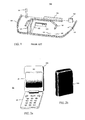
- Figs. 2a and 2b show an example of a radiating antenna element according to the invention. The
antenna element 200 belongs to a radio device depicted in Fig. 2a which in this example is afoldable communication device 20. The communication device has afirst part 21 and a second part 22 which can be turned with respect to one another around a hinge located between them. Fig. 2b shows just theantenna element 200. This is a single conductive piece constituting the back side and relatively narrow lateral sides and the upper end side of the cover of thefirst part 21. It may be made of aluminum by extruding, for example. The size of the antenna element is not bound to the wavelength corresponding to an operating frequency. The element is large compared to a quarter of the wavelength, enabling good radiation and receive characteristics. The location of the radiator on the outer surface of the radio device has the same effect. In the end product, theantenna element 200 as well as the antenna elements of Figs. 3 to 7 and 9 to 10 are naturally coated with a thin protective layer. - Figs. 3a and 3b show a second example of a radiating antenna element according to the invention. The
antenna element 300 belongs to aradio device 30 which in this example is an ordinary non-foldable mobile communication device. In Fig. 3a the communication device is seen from behind and in Fig. 3b from a side. Theantenna element 300 is a single conductive piece forming about one half of the back side of the cover of thecommunication device 30, extending to the lateral sides and end side, too. Theelement 300 connects to therest 35 of the cover of the radio device without any discontinuity of the outer surface. - Figs. 4a and 4b show a third example of a radiating antenna element according to the invention. An
antenna element 400 belongs to aradio device 40 which in this case, too, is an ordinary non-foldable mobile communication device. In Fig. 4a the communication device is seen from behind and in Fig. 4b from a side. Theantenna element 400 is a single conductive piece forming the whole of the back side of the cover of thecommunication device 40, extending to the lateral sides and end side, too. The radiator is thus in this example particularly large. It connects to therest 45 of the cover of the radio device without any discontinuity of the outer surface. - Figs. 5a and 5b show a fourth example of a radiating antenna element according to the invention. An
antenna element 500 belongs to aradio device 50 which in this case, too, is an ordinary non-foldable mobile communication device. In Fig. 5a the communication device is seen from behind and in Fig. 5b there is shown just theantenna element 500. This is a single cuplike conductive piece forming the upper portion of the cover of thecommunication device 50. Thus theradiator 500 will be overlapped only a little when held in hand in the normal manner. The antenna element connects to therest 55 of the cover of the radio device without any discontinuity of the outer surface. - Fig. 6 shows a sixth example of a radiating antenna element according to the invention. An
antenna element 600 is now a single trough-like conductive piece constituting an intermediate part of the back side of the cover of a radio device. - Fig. 7 shows in cross section a sixth example of an antenna element according to the invention. An
antenna element 700 consists now of adielectric portion 710 in the cover of a radio device, a radiatingconductive layer 720 on the outer surface thereof, and a conductive layer on the inner surface thereof, i.e. afeed element 730. The antenna element is fabricated using e.g. IMF (In Mould Foil), IMD (In Mould Decoration) or IML (In Mould Label) technology, so that it is a solid single component. - Below the
antenna element 700 there is an antenna ground plane GND provided by the conductive upper surface of the circuit board PCB of the radio device. There is only electromagnetic coupling between thefeed element 730 andradiator 720 because thedielectric cover 710 isolates them galvanically from each other. Furthermore, theradiator 720 is not galvanically connected to any other conductive part of the radio device. Thefeed element 730 is galvanically connected to the antenna port of the radio device by a feed conductor FDC and to the ground plane by a short-circuit conductor SHC. In this example the feed and short-circuit conductors are conductive strips attached to the antenna element, which are pressed against the circuit board PCB by a spring force. - Fig. 8 shows a seventh example of an antenna element according to the invention. An
antenna element 800 consists of adielectric portion 810 of the cover of a radio device, a radiatingconductive layer 820 therein, and a conductive layer on the inner surface, i.e. thefeed element 830. The difference of this antenna element from theantenna element 700 of Fig. 7 is that the radiator is now within the dielectric cover and not on the outer surface thereof. Theantenna element 800 can be fabricated using the same above-mentioned techniques as in fabricating theelement 700. Alternatively, in the examples of Figs. 7 and 8, also the feed element may be embedded within the dielectric portion of the antenna element. - Fig. 9 shows a second example of the feed arrangement of an antenna element according to the invention. This figure shows a radiating
antenna element 900 which is a single conductive piece. Below the antenna element there is the ground plane GND of the antenna. Between theradiator 900 and ground plane there is a conductive feed element FDE which in this example is galvanically isolated from the radiator by a separate thin dielectric layer DIE. The radiator is not galvanically connected to any conductive part in the radio device. The feed element FDE is galvanically connected to the antenna port of the radio device by a feed conductor FDC and to the ground plane by a short-circuit conductor SHC. Encircled within a broken line there is an example of the shape of the feed element FDE. It is a conductive strip which has two branches of different lengths, viewed from the short-circuit point S, to produce two operating bands for the antenna. The longer branch together with the radiating antenna element and ground plane resonates in the lower operating band area, and the shorter branch together with the radiating antenna element and ground plane resonates in the upper operating band area. - Fig. 10 shows in cross section a third example of the feed arrangement of an antenna element according to the invention. In this figure there is shown a radiating antenna element A00 and, below that, the ground plane GND of the antenna. The radiator A00 is now galvanically connected to the antenna port of the radio device by a feed conductor FDC and to the ground plane by a short-circuit conductor SHC. The antenna is thus PIFA type. The feed and short circuit conductors are e.g. so-called pogo pins, in which case their internal springs press the upper parts of the conductors against the radiator. A direct feed to the radiating element according to Fig. 10 requires that, in the element design, not only the desired appearance of the radio device need to be known, but also the electrical dimensions of the element need to be taken into account.
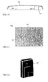
- The radiating portion of an antenna element according to the invention is advantageously "unbroken", i.e. its border line will not deviate inwards from the, say, rectangular or roundish outline of the element. This is possible especially when using the feed arrangement according to Figs. 7 to 9. However, in order to enhance the electrical characteristics of the antenna, the radiating portion may be shaped as required. Fig. 11 shows an example of such an antenna element. The element B00 includes a dielectric portion B10 and a radiating portion B20. The radiating portion is inside the dielectric portion and therefore drawn in broken line. The radiating portion has ends extending perpendicularly from its middle region so that a pattern is formed which resembles a wide rectangular U. For example, the radiating
portion 720 of the element of Fig. 7 or the radiatingportion 820 of the element of Fig. 8 may be shaped like portion B20. - Fig. 12 shows a second example of a shaped radiator. The radiating portion C00 has two non-conductive slots. From the lower edge starts a first slot C05 shaped like letter L and a straight second slot C06. In a complete radio device there is a dielectric protective layer on top of the slots and the whole radiator.
- The attributes "lower" and "upper" refer in this description and in the claims to the positions of the antenna element presented in Figs. 5a and 7 to 10 and have nothing to do with the operating positions of the devices.
- Antenna elements according to the invention were described above. The shape of an antenna element may differ from those presented, and the invention does not limit the fabricating method of the element. The inventional idea can be applied in different ways within the scope defined by the independent claim 1.
Claims (17)
- A radiating antenna element of a radio device, which element is part of cover of the radio device, characterized in that it (200; 300; 400; 500; 600; 700; 800; 900; A00; B00; C00) has a size which is substantially greater than a quarter of the wavelength corresponding to an operating frequency.
- The antenna element according to claim 1, characterized in that its radiating portion is galvanically isolated from the other conductive parts of the radio device.
- The antenna element according to claim 2, characterized in that its radiating portion (720; 820; 900) is arranged to be fed electromagnetically by a feed element (730; 830; FDE).
- The antenna element of a radio device according to claim 1, which radio device (20) is foldable comprising two folding parts, characterized in that it (200) comprises a rear part of the cover of one (21) of said folding parts.
- The antenna element according to claim 1, characterized in that it (300) comprises an upper portion of a rear part of the cover of a radio device (30).
- The antenna element according to claim 1, characterized in that it (400) comprises whole rear part of the cover of a radio device (40).
- The antenna element according to claim 1, characterized in that it (600; B00) comprises an intermediate portion of a rear part of the cover of a radio device.
- The antenna element according to claim 1, characterized in that it (500) comprises an upper portion of the cover of a radio device (50).
- The antenna element according to claim 1, characterized in that it is a rigid conductive piece forming said part of a radio device substantially entirely.
- The antenna element according to claim 1, characterized in that it has a dielectric portion (710; 810; B10) and a radiating portion (720; 820; B20) which portions together constitute a single integral component.
- The antenna element according to claim 10, characterized in that the radiating portion (720) is located on outer surface of the dielectric portion (710).
- The antenna element according to claim 10, characterized in that the radiating portion (820) is located within the dielectric portion (810).
- The antenna element according to claim 10, characterized in that it further comprises an antenna feed element (730; 830) which together with the dielectric portion and radiating portion form a single integral component.
- The antenna element according to claim 13, characterized in that the feed element (830) is located on inner surface of the dielectric portion (810).
- The antenna element according to claim 13, characterized in that the feed element is located within the dielectric portion.
- The antenna element according to claim 1, characterized in that its radiating portion (B20; C00) is shaped to match the antenna.
- A radio device (20; 30; 40; 50) a radiating antenna element of which is part of cover of the radio device, characterized in that the antenna element (200; 300; 400; 500) has a size which is substantially greater than a quarter of the wavelength corresponding to the operating frequency.
Applications Claiming Priority (4)
| Application Number | Priority Date | Filing Date | Title |
|---|---|---|---|
| FI20030059 | 2003-01-15 | ||
| FI20030059A FI113586B (en) | 2003-01-15 | 2003-01-15 | Internal multiband antenna for radio device, has feed unit connected to ground plane at short-circuit point that divides feed unit into two portions which along with radiating unit and plane resonates in antenna operating range |
| FI20030193 | 2003-02-07 | ||
| FI20030193A FI116334B (en) | 2003-01-15 | 2003-02-07 | The antenna element |
Publications (1)
| Publication Number | Publication Date |
|---|---|
| EP1439603A1 true EP1439603A1 (en) | 2004-07-21 |
Family
ID=26161344
Family Applications (1)
| Application Number | Title | Priority Date | Filing Date |
|---|---|---|---|
| EP04396003A Withdrawn EP1439603A1 (en) | 2003-01-15 | 2004-01-09 | Antenna element as part of the cover of a radio device |
Country Status (4)
| Country | Link |
|---|---|
| US (1) | US7391378B2 (en) |
| EP (1) | EP1439603A1 (en) |
| CN (1) | CN1519980A (en) |
| FI (1) | FI116334B (en) |
Cited By (23)
| Publication number | Priority date | Publication date | Assignee | Title |
|---|---|---|---|---|
| WO2005034286A1 (en) * | 2003-10-09 | 2005-04-14 | Lk Products Oy | Cover structure for a radio device |
| EP1667282A1 (en) * | 2004-12-06 | 2006-06-07 | LG Electronics Inc. | Antenna having radiating part formed flush with surface of casing part |
| WO2008069750A1 (en) * | 2006-12-08 | 2008-06-12 | Perlos Oyj | Antenna for mobile terminal unit |
| EP1988601A1 (en) * | 2006-02-19 | 2008-11-05 | Nissha Printing Co., Ltd. | Feeding structure of housing with antenna |
| WO2009027111A1 (en) * | 2007-08-29 | 2009-03-05 | Sony Ericsson Mobile Communications Ab | Electrically conductive casing of a portable communication device as fm antenna |
| EP2092598A1 (en) * | 2006-11-15 | 2009-08-26 | Pulse Finland Oy | Internal multi-band antenna |
| US7825862B2 (en) | 2007-06-01 | 2010-11-02 | Getac Technology Corporation | Antenna device with surface antenna pattern integrally coated casing of electronic device |
| EP2250702A1 (en) * | 2008-02-28 | 2010-11-17 | Pulse Finland Oy | Adjustable multiband antenna |
| US8466756B2 (en) | 2007-04-19 | 2013-06-18 | Pulse Finland Oy | Methods and apparatus for matching an antenna |
| US8473017B2 (en) | 2005-10-14 | 2013-06-25 | Pulse Finland Oy | Adjustable antenna and methods |
| US8564485B2 (en) | 2005-07-25 | 2013-10-22 | Pulse Finland Oy | Adjustable multiband antenna and methods |
| US8618990B2 (en) | 2011-04-13 | 2013-12-31 | Pulse Finland Oy | Wideband antenna and methods |
| US8629813B2 (en) | 2007-08-30 | 2014-01-14 | Pusle Finland Oy | Adjustable multi-band antenna and methods |
| US8648752B2 (en) | 2011-02-11 | 2014-02-11 | Pulse Finland Oy | Chassis-excited antenna apparatus and methods |
| US8786499B2 (en) | 2005-10-03 | 2014-07-22 | Pulse Finland Oy | Multiband antenna system and methods |
| US8847833B2 (en) | 2009-12-29 | 2014-09-30 | Pulse Finland Oy | Loop resonator apparatus and methods for enhanced field control |
| US8988290B2 (en) | 2008-11-15 | 2015-03-24 | Nokia Corporation | Apparatus and method of providing an apparatus |
| US9246210B2 (en) | 2010-02-18 | 2016-01-26 | Pulse Finland Oy | Antenna with cover radiator and methods |
| EP2988367A1 (en) * | 2014-08-18 | 2016-02-24 | Samsung Electronics Co., Ltd. | Antenna of electronic device |
| DE102008041582B4 (en) * | 2007-09-13 | 2016-02-25 | Getac Technology Corp. | Antenna device having a surface antenna pattern integrally coated on the housing of the electronic device |
| US9406998B2 (en) | 2010-04-21 | 2016-08-02 | Pulse Finland Oy | Distributed multiband antenna and methods |
| US9450291B2 (en) | 2011-07-25 | 2016-09-20 | Pulse Finland Oy | Multiband slot loop antenna apparatus and methods |
| US9673507B2 (en) | 2011-02-11 | 2017-06-06 | Pulse Finland Oy | Chassis-excited antenna apparatus and methods |
Families Citing this family (59)
| Publication number | Priority date | Publication date | Assignee | Title |
|---|---|---|---|---|
| US7423592B2 (en) | 2004-01-30 | 2008-09-09 | Fractus, S.A. | Multi-band monopole antennas for mobile communications devices |
| CN1784808A (en) * | 2003-05-09 | 2006-06-07 | 皇家飞利浦电子股份有限公司 | Antenna integrated into a housing |
| TWM241906U (en) * | 2003-05-16 | 2004-08-21 | Asustek Comp Inc | Electronic product with hidden antenna |
| FI115573B (en) * | 2003-06-11 | 2005-05-31 | Filtronic Lk Oy | Foldable radio antenna |
| WO2006000650A1 (en) | 2004-06-28 | 2006-01-05 | Pulse Finland Oy | Antenna component |
| US7372411B2 (en) * | 2004-06-28 | 2008-05-13 | Nokia Corporation | Antenna arrangement and method for making the same |
| FI119577B (en) * | 2005-11-24 | 2008-12-31 | Pulse Finland Oy | The multiband antenna component |
| US7936307B2 (en) | 2006-07-24 | 2011-05-03 | Nokia Corporation | Cover antennas |
| US10211538B2 (en) | 2006-12-28 | 2019-02-19 | Pulse Finland Oy | Directional antenna apparatus and methods |
| KR20090006336A (en) * | 2007-07-11 | 2009-01-15 | 삼성전기주식회사 | A antenna integrated with case and fabrication method thereof |
| KR101545019B1 (en) * | 2007-09-05 | 2015-08-18 | 삼성전자주식회사 | Lds electronic device method using laser direct structure and electronic device thereby |
| US8421682B2 (en) * | 2007-12-21 | 2013-04-16 | Nokia Corporation | Apparatus, methods and computer programs for wireless communication |
| US7876273B2 (en) * | 2007-12-21 | 2011-01-25 | Nokia Corporation | Apparatus and method |
| KR101044994B1 (en) | 2008-06-20 | 2011-06-29 | 삼성전자주식회사 | Antenna apparatus of potable terminal |
| CN101908667A (en) * | 2009-09-10 | 2010-12-08 | 深圳富泰宏精密工业有限公司 | Shell of electronic device and manufacturing method thereof |
| CN102035069A (en) * | 2009-09-30 | 2011-04-27 | 深圳富泰宏精密工业有限公司 | Portable electronic device |
| CN102576928A (en) * | 2009-10-29 | 2012-07-11 | 莱尔德技术股份有限公司 | A metal cover for a radio communication device |
| FI20096134A0 (en) | 2009-11-03 | 2009-11-03 | Pulse Finland Oy | Adjustable antenna |
| FI20096251A0 (en) | 2009-11-27 | 2009-11-27 | Pulse Finland Oy | MIMO antenna |
| CN101728630B (en) * | 2009-12-21 | 2013-07-10 | 瑞声声学科技(深圳)有限公司 | Electronic communication equipment and manufacturing process thereof |
| WO2011095330A1 (en) | 2010-02-02 | 2011-08-11 | Fractus, S.A. | Antennaless wireless device comprising one or more bodies |
| KR101101468B1 (en) * | 2010-03-15 | 2012-01-03 | 삼성전기주식회사 | Case of electronic device and mould for manufacturing the same, and mobile communication terminal |
| US10063678B2 (en) | 2010-07-23 | 2018-08-28 | Blackberry Limited | System for controlling current along a housing of a mobile wireless communications device |
| US8615279B2 (en) * | 2010-07-23 | 2013-12-24 | Blackberry Limited | Mobile wireless communications device with shunt component and related methods |
| US8774880B2 (en) * | 2010-07-23 | 2014-07-08 | Blackberry Limited | Mobile wireless communications device with electrically conductive continuous ring and related methods |
| CA2747147C (en) * | 2010-07-23 | 2015-04-21 | Research In Motion Limited | Mobile wireless communications device with electrically conductive continuous ring and related methods |
| WO2012017013A1 (en) | 2010-08-03 | 2012-02-09 | Fractus, S.A. | Wireless device capable of multiband mimo operation |
| FI20115072A0 (en) | 2011-01-25 | 2011-01-25 | Pulse Finland Oy | Multi-resonance antenna, antenna module and radio unit |
| FI127080B (en) * | 2011-06-10 | 2017-10-31 | Lite-On Mobile Oyj | An antenna arrangement and an electronic device |
| US8866689B2 (en) | 2011-07-07 | 2014-10-21 | Pulse Finland Oy | Multi-band antenna and methods for long term evolution wireless system |
| US9123990B2 (en) | 2011-10-07 | 2015-09-01 | Pulse Finland Oy | Multi-feed antenna apparatus and methods |
| US9041606B2 (en) * | 2011-11-30 | 2015-05-26 | Motorola Solutions, Inc. | Uninterrupted bezel antenna |
| US9531058B2 (en) | 2011-12-20 | 2016-12-27 | Pulse Finland Oy | Loosely-coupled radio antenna apparatus and methods |
| US9484619B2 (en) | 2011-12-21 | 2016-11-01 | Pulse Finland Oy | Switchable diversity antenna apparatus and methods |
| CN103327139B (en) * | 2012-03-23 | 2018-11-13 | 联想(北京)有限公司 | Electronic equipment and its constructive method |
| US8988296B2 (en) | 2012-04-04 | 2015-03-24 | Pulse Finland Oy | Compact polarized antenna and methods |
| JP5525574B2 (en) * | 2012-08-07 | 2014-06-18 | ホシデン株式会社 | Component module and component module manufacturing method |
| JP5484529B2 (en) * | 2012-08-07 | 2014-05-07 | ホシデン株式会社 | Component module and component module manufacturing method |
| CN103682565A (en) * | 2012-09-17 | 2014-03-26 | 联想(北京)有限公司 | Antenna and antenna forming method |
| US9979078B2 (en) | 2012-10-25 | 2018-05-22 | Pulse Finland Oy | Modular cell antenna apparatus and methods |
| US10069209B2 (en) | 2012-11-06 | 2018-09-04 | Pulse Finland Oy | Capacitively coupled antenna apparatus and methods |
| US10079428B2 (en) | 2013-03-11 | 2018-09-18 | Pulse Finland Oy | Coupled antenna structure and methods |
| US9647338B2 (en) | 2013-03-11 | 2017-05-09 | Pulse Finland Oy | Coupled antenna structure and methods |
| US9634383B2 (en) | 2013-06-26 | 2017-04-25 | Pulse Finland Oy | Galvanically separated non-interacting antenna sector apparatus and methods |
| CN104466389A (en) * | 2013-09-24 | 2015-03-25 | 联想(北京)有限公司 | Electronic device |
| CN203589215U (en) * | 2013-10-18 | 2014-05-07 | 上海安费诺永亿通讯电子有限公司 | Mobile phone terminal composite antenna |
| CN103606741B (en) * | 2013-10-18 | 2016-06-08 | 上海安费诺永亿通讯电子有限公司 | A kind of multiplex antenna collecting diversity reception, GPS and WIFI communication |
| US9680212B2 (en) | 2013-11-20 | 2017-06-13 | Pulse Finland Oy | Capacitive grounding methods and apparatus for mobile devices |
| US9590308B2 (en) | 2013-12-03 | 2017-03-07 | Pulse Electronics, Inc. | Reduced surface area antenna apparatus and mobile communications devices incorporating the same |
| US9350081B2 (en) | 2014-01-14 | 2016-05-24 | Pulse Finland Oy | Switchable multi-radiator high band antenna apparatus |
| KR102129249B1 (en) | 2014-04-28 | 2020-07-02 | 삼성전자주식회사 | Antenna apparatus and electronic device including the same |
| US9973228B2 (en) | 2014-08-26 | 2018-05-15 | Pulse Finland Oy | Antenna apparatus with an integrated proximity sensor and methods |
| US9948002B2 (en) | 2014-08-26 | 2018-04-17 | Pulse Finland Oy | Antenna apparatus with an integrated proximity sensor and methods |
| US9722308B2 (en) | 2014-08-28 | 2017-08-01 | Pulse Finland Oy | Low passive intermodulation distributed antenna system for multiple-input multiple-output systems and methods of use |
| KR102245184B1 (en) | 2014-11-21 | 2021-04-27 | 삼성전자주식회사 | Electronic device with antenna |
| KR102330024B1 (en) | 2015-03-27 | 2021-11-23 | 삼성전자 주식회사 | Antenna apparatus and electronic device including the same |
| US9906260B2 (en) | 2015-07-30 | 2018-02-27 | Pulse Finland Oy | Sensor-based closed loop antenna swapping apparatus and methods |
| CN105406196B (en) * | 2015-10-26 | 2018-04-03 | 瑞声精密制造科技(常州)有限公司 | Antenna modules and the mobile terminal using the antenna modules |
| CN109315074B (en) * | 2016-06-23 | 2022-03-01 | 东丽株式会社 | Housing and method for manufacturing housing |
Citations (6)
| Publication number | Priority date | Publication date | Assignee | Title |
|---|---|---|---|---|
| US4800392A (en) * | 1987-01-08 | 1989-01-24 | Motorola, Inc. | Integral laminar antenna and radio housing |
| JPH11127010A (en) | 1997-10-22 | 1999-05-11 | Sony Corp | Antenna system and portable radio equipment |
| US20020053991A1 (en) | 2000-10-27 | 2002-05-09 | Bo Lindell | Arrangement for a mobile terminal |
| US6396444B1 (en) * | 1998-12-23 | 2002-05-28 | Nokia Mobile Phones Limited | Antenna and method of production |
| US6452551B1 (en) * | 2001-08-02 | 2002-09-17 | Auden Techno Corp. | Capacitor-loaded type single-pole planar antenna |
| EP1271690A2 (en) | 2001-06-29 | 2003-01-02 | Nokia Corporation | An antenna |
Family Cites Families (12)
| Publication number | Priority date | Publication date | Assignee | Title |
|---|---|---|---|---|
| JPH02125503A (en) | 1988-11-04 | 1990-05-14 | Kokusai Electric Co Ltd | Small sized antenna |
| EP0851530A3 (en) | 1996-12-28 | 2000-07-26 | Lucent Technologies Inc. | Antenna apparatus in wireless terminals |
| FI112983B (en) | 1997-12-10 | 2004-02-13 | Nokia Corp | Antenna |
| DE69941025D1 (en) | 1999-07-09 | 2009-08-06 | Ipcom Gmbh & Co Kg | Two band radio |
| US6603430B1 (en) * | 2000-03-09 | 2003-08-05 | Tyco Electronics Logistics Ag | Handheld wireless communication devices with antenna having parasitic element |
| JP3600117B2 (en) | 2000-05-15 | 2004-12-08 | シャープ株式会社 | Mobile phone |
| US6677903B2 (en) * | 2000-12-04 | 2004-01-13 | Arima Optoelectronics Corp. | Mobile communication device having multiple frequency band antenna |
| JP4598267B2 (en) * | 2000-12-26 | 2010-12-15 | レノボ シンガポール プライヴェート リミテッド | Transmission device, computer system, and opening / closing structure |
| JP2002299933A (en) | 2001-04-02 | 2002-10-11 | Murata Mfg Co Ltd | Electrode structure for antenna and communication equipment provided with the same |
| EP1306922A3 (en) * | 2001-10-24 | 2006-08-16 | Matsushita Electric Industrial Co., Ltd. | Antenna structure, methof of using antenna structure and communication device |
| JP2003140773A (en) * | 2001-10-31 | 2003-05-16 | Toshiba Corp | Radio communication device and information processor |
| FI115342B (en) * | 2001-11-15 | 2005-04-15 | Filtronic Lk Oy | Method of making an internal antenna and antenna element |
-
2003
- 2003-02-07 FI FI20030193A patent/FI116334B/en not_active IP Right Cessation
-
2004
- 2004-01-07 US US10/753,887 patent/US7391378B2/en active Active
- 2004-01-09 EP EP04396003A patent/EP1439603A1/en not_active Withdrawn
- 2004-01-15 CN CNA2004100018726A patent/CN1519980A/en active Pending
Patent Citations (6)
| Publication number | Priority date | Publication date | Assignee | Title |
|---|---|---|---|---|
| US4800392A (en) * | 1987-01-08 | 1989-01-24 | Motorola, Inc. | Integral laminar antenna and radio housing |
| JPH11127010A (en) | 1997-10-22 | 1999-05-11 | Sony Corp | Antenna system and portable radio equipment |
| US6396444B1 (en) * | 1998-12-23 | 2002-05-28 | Nokia Mobile Phones Limited | Antenna and method of production |
| US20020053991A1 (en) | 2000-10-27 | 2002-05-09 | Bo Lindell | Arrangement for a mobile terminal |
| EP1271690A2 (en) | 2001-06-29 | 2003-01-02 | Nokia Corporation | An antenna |
| US6452551B1 (en) * | 2001-08-02 | 2002-09-17 | Auden Techno Corp. | Capacitor-loaded type single-pole planar antenna |
Non-Patent Citations (1)
| Title |
|---|
| PATENT ABSTRACTS OF JAPAN vol. 1999, no. 10 31 August 1999 (1999-08-31) * |
Cited By (32)
| Publication number | Priority date | Publication date | Assignee | Title |
|---|---|---|---|---|
| WO2005034286A1 (en) * | 2003-10-09 | 2005-04-14 | Lk Products Oy | Cover structure for a radio device |
| US7340286B2 (en) | 2003-10-09 | 2008-03-04 | Lk Products Oy | Cover structure for a radio device |
| EP1667282A1 (en) * | 2004-12-06 | 2006-06-07 | LG Electronics Inc. | Antenna having radiating part formed flush with surface of casing part |
| US8564485B2 (en) | 2005-07-25 | 2013-10-22 | Pulse Finland Oy | Adjustable multiband antenna and methods |
| US8786499B2 (en) | 2005-10-03 | 2014-07-22 | Pulse Finland Oy | Multiband antenna system and methods |
| US8473017B2 (en) | 2005-10-14 | 2013-06-25 | Pulse Finland Oy | Adjustable antenna and methods |
| EP1988601A1 (en) * | 2006-02-19 | 2008-11-05 | Nissha Printing Co., Ltd. | Feeding structure of housing with antenna |
| EP1988601A4 (en) * | 2006-02-19 | 2009-04-08 | Nissha Printing | Feeding structure of housing with antenna |
| EP2092598A4 (en) * | 2006-11-15 | 2009-12-16 | Pulse Finland Oy | Internal multi-band antenna |
| EP2092598A1 (en) * | 2006-11-15 | 2009-08-26 | Pulse Finland Oy | Internal multi-band antenna |
| WO2008069750A1 (en) * | 2006-12-08 | 2008-06-12 | Perlos Oyj | Antenna for mobile terminal unit |
| US8537072B2 (en) | 2006-12-08 | 2013-09-17 | Lite-On Mobile Oyj | Antenna for mobile terminal unit |
| US8466756B2 (en) | 2007-04-19 | 2013-06-18 | Pulse Finland Oy | Methods and apparatus for matching an antenna |
| US7825862B2 (en) | 2007-06-01 | 2010-11-02 | Getac Technology Corporation | Antenna device with surface antenna pattern integrally coated casing of electronic device |
| WO2009027111A1 (en) * | 2007-08-29 | 2009-03-05 | Sony Ericsson Mobile Communications Ab | Electrically conductive casing of a portable communication device as fm antenna |
| US7856259B2 (en) | 2007-08-29 | 2010-12-21 | Sony Ericsson Mobile Communications Ab | In-built FM antenna |
| US8629813B2 (en) | 2007-08-30 | 2014-01-14 | Pusle Finland Oy | Adjustable multi-band antenna and methods |
| DE102008041582B4 (en) * | 2007-09-13 | 2016-02-25 | Getac Technology Corp. | Antenna device having a surface antenna pattern integrally coated on the housing of the electronic device |
| EP2250702A4 (en) * | 2008-02-28 | 2011-10-05 | Pulse Finland Oy | Adjustable multiband antenna |
| EP2250702A1 (en) * | 2008-02-28 | 2010-11-17 | Pulse Finland Oy | Adjustable multiband antenna |
| US8988290B2 (en) | 2008-11-15 | 2015-03-24 | Nokia Corporation | Apparatus and method of providing an apparatus |
| US8847833B2 (en) | 2009-12-29 | 2014-09-30 | Pulse Finland Oy | Loop resonator apparatus and methods for enhanced field control |
| US9246210B2 (en) | 2010-02-18 | 2016-01-26 | Pulse Finland Oy | Antenna with cover radiator and methods |
| US9406998B2 (en) | 2010-04-21 | 2016-08-02 | Pulse Finland Oy | Distributed multiband antenna and methods |
| US8648752B2 (en) | 2011-02-11 | 2014-02-11 | Pulse Finland Oy | Chassis-excited antenna apparatus and methods |
| US9673507B2 (en) | 2011-02-11 | 2017-06-06 | Pulse Finland Oy | Chassis-excited antenna apparatus and methods |
| US9917346B2 (en) | 2011-02-11 | 2018-03-13 | Pulse Finland Oy | Chassis-excited antenna apparatus and methods |
| US8618990B2 (en) | 2011-04-13 | 2013-12-31 | Pulse Finland Oy | Wideband antenna and methods |
| US9450291B2 (en) | 2011-07-25 | 2016-09-20 | Pulse Finland Oy | Multiband slot loop antenna apparatus and methods |
| EP2988367A1 (en) * | 2014-08-18 | 2016-02-24 | Samsung Electronics Co., Ltd. | Antenna of electronic device |
| US9859607B2 (en) | 2014-08-18 | 2018-01-02 | Samsung Electronics Co., Ltd | Antenna of electronic device |
| US10547101B2 (en) | 2014-08-18 | 2020-01-28 | Samsung Electronics Co., Ltd | Antenna of electronic device |
Also Published As
| Publication number | Publication date |
|---|---|
| FI20030193A (en) | 2004-07-16 |
| US20040147297A1 (en) | 2004-07-29 |
| FI20030193A0 (en) | 2003-02-07 |
| CN1519980A (en) | 2004-08-11 |
| US7391378B2 (en) | 2008-06-24 |
| FI116334B (en) | 2005-10-31 |
Similar Documents
| Publication | Publication Date | Title |
|---|---|---|
| US7391378B2 (en) | Antenna element for a radio device | |
| US7501983B2 (en) | Planar antenna structure and radio device | |
| US6806834B2 (en) | Multi band built-in antenna | |
| US6950068B2 (en) | Method of manufacturing an internal antenna, and antenna element | |
| US7088307B2 (en) | Antenna matching circuit, mobile communication device including antenna matching circuit, and dielectric antenna including antenna matching circuit | |
| US6246371B1 (en) | Wide band antenna means incorporating a radiating structure having a band form | |
| US6963308B2 (en) | Multiband antenna | |
| US6937196B2 (en) | Internal multiband antenna | |
| US8786500B2 (en) | Built-in antenna and method for improving antenna efficiency | |
| US7352326B2 (en) | Multiband planar antenna | |
| US7602343B2 (en) | Antenna | |
| EP1096602A1 (en) | Planar antenna | |
| EP1432072A1 (en) | Antenna for flat radio device | |
| EP1911121A2 (en) | Antenna with inner spring contact | |
| US20130050038A1 (en) | Antenna apparatus of mobile terminal | |
| US20130127674A1 (en) | Antenna with cover radiator and methods | |
| WO2005038981A1 (en) | Internal multiband antenna | |
| CN101981754A (en) | Built-in antenna for supporting impedance matching for multiband | |
| EP1717901B1 (en) | Built-in type antenna apparatus for portable terminal | |
| JP4169696B2 (en) | High bandwidth multiband antenna | |
| US6567047B2 (en) | Multi-band in-series antenna assembly | |
| JP4723947B2 (en) | Dual frequency antenna | |
| JP2007336331A (en) | Antenna device | |
| US20080204346A1 (en) | Antenna adjusting method and antenna device | |
| KR100688648B1 (en) | Multi-band internal antenna using a short stub for mobile terminals |
Legal Events
| Date | Code | Title | Description |
|---|---|---|---|
| PUAI | Public reference made under article 153(3) epc to a published international application that has entered the european phase |
Free format text: ORIGINAL CODE: 0009012 |
|
| AK | Designated contracting states |
Kind code of ref document: A1 Designated state(s): AT BE BG CH CY CZ DE DK EE ES FI FR GB GR HU IE IT LI LU MC NL PT RO SE SI SK TR |
|
| AX | Request for extension of the european patent |
Extension state: AL LT LV MK |
|
| 17P | Request for examination filed |
Effective date: 20050120 |
|
| AKX | Designation fees paid |
Designated state(s): AT BE BG CH CY CZ DE DK EE ES FI FR GB GR HU IE IT LI LU MC NL PT RO SE SI SK TR |
|
| RAP1 | Party data changed (applicant data changed or rights of an application transferred) |
Owner name: LK PRODUCTS OY |
|
| RAP1 | Party data changed (applicant data changed or rights of an application transferred) |
Owner name: PULSE FINLAND OY |
|
| 17Q | First examination report despatched |
Effective date: 20120420 |
|
| STAA | Information on the status of an ep patent application or granted ep patent |
Free format text: STATUS: THE APPLICATION IS DEEMED TO BE WITHDRAWN |
|
| 18D | Application deemed to be withdrawn |
Effective date: 20130801 |