EP1440640A2 - Machine for the preparation of beverages - Google Patents
Machine for the preparation of beverages Download PDFInfo
- Publication number
- EP1440640A2 EP1440640A2 EP04250390A EP04250390A EP1440640A2 EP 1440640 A2 EP1440640 A2 EP 1440640A2 EP 04250390 A EP04250390 A EP 04250390A EP 04250390 A EP04250390 A EP 04250390A EP 1440640 A2 EP1440640 A2 EP 1440640A2
- Authority
- EP
- European Patent Office
- Prior art keywords
- beverage
- cartridge
- beverage preparation
- low pressure
- cartridges
- Prior art date
- Legal status (The legal status is an assumption and is not a legal conclusion. Google has not performed a legal analysis and makes no representation as to the accuracy of the status listed.)
- Granted
Links
- 235000013361 beverage Nutrition 0.000 title claims abstract description 351
- 238000002360 preparation method Methods 0.000 title claims abstract description 88
- 239000004615 ingredient Substances 0.000 claims abstract description 55
- 238000012545 processing Methods 0.000 claims abstract description 5
- 235000013353 coffee beverage Nutrition 0.000 claims description 39
- 235000013336 milk Nutrition 0.000 claims description 39
- 239000008267 milk Substances 0.000 claims description 39
- 210000004080 milk Anatomy 0.000 claims description 39
- 235000016213 coffee Nutrition 0.000 claims description 38
- 239000012736 aqueous medium Substances 0.000 claims description 30
- 239000007788 liquid Substances 0.000 claims description 25
- 238000000034 method Methods 0.000 claims description 18
- 235000019219 chocolate Nutrition 0.000 claims description 16
- 238000010926 purge Methods 0.000 claims description 16
- 241001122767 Theaceae Species 0.000 claims description 13
- 235000013616 tea Nutrition 0.000 claims description 13
- 238000005187 foaming Methods 0.000 claims description 11
- 235000015116 cappuccino Nutrition 0.000 claims description 6
- 230000003287 optical effect Effects 0.000 claims description 6
- 235000013365 dairy product Nutrition 0.000 claims description 5
- 235000015203 fruit juice Nutrition 0.000 claims description 4
- 235000014347 soups Nutrition 0.000 claims description 4
- 235000011850 desserts Nutrition 0.000 claims description 3
- 235000015067 sauces Nutrition 0.000 claims description 3
- 241000269627 Amphiuma means Species 0.000 claims description 2
- 230000000977 initiatory effect Effects 0.000 claims description 2
- XLYOFNOQVPJJNP-UHFFFAOYSA-N water Substances O XLYOFNOQVPJJNP-UHFFFAOYSA-N 0.000 description 73
- 208000028659 discharge Diseases 0.000 description 36
- 239000000463 material Substances 0.000 description 24
- 238000002156 mixing Methods 0.000 description 20
- 239000000047 product Substances 0.000 description 19
- 238000001914 filtration Methods 0.000 description 17
- 244000299461 Theobroma cacao Species 0.000 description 14
- 239000004743 Polypropylene Substances 0.000 description 10
- 239000012263 liquid product Substances 0.000 description 10
- 238000010790 dilution Methods 0.000 description 8
- 239000012895 dilution Substances 0.000 description 8
- -1 polypropylene Polymers 0.000 description 8
- 239000007787 solid Substances 0.000 description 8
- 230000007246 mechanism Effects 0.000 description 7
- 229920003023 plastic Polymers 0.000 description 7
- 239000004033 plastic Substances 0.000 description 7
- 239000004411 aluminium Substances 0.000 description 6
- 229910052782 aluminium Inorganic materials 0.000 description 6
- XAGFODPZIPBFFR-UHFFFAOYSA-N aluminium Chemical compound [Al] XAGFODPZIPBFFR-UHFFFAOYSA-N 0.000 description 6
- 238000004891 communication Methods 0.000 description 6
- 229920001155 polypropylene Polymers 0.000 description 6
- 238000003466 welding Methods 0.000 description 6
- 230000009471 action Effects 0.000 description 5
- 239000011248 coating agent Substances 0.000 description 5
- 238000000576 coating method Methods 0.000 description 5
- 238000005304 joining Methods 0.000 description 5
- 230000004888 barrier function Effects 0.000 description 4
- 239000012530 fluid Substances 0.000 description 4
- 239000006260 foam Substances 0.000 description 4
- 230000006870 function Effects 0.000 description 4
- 230000007704 transition Effects 0.000 description 4
- 240000007154 Coffea arabica Species 0.000 description 3
- 239000004698 Polyethylene Substances 0.000 description 3
- 238000010276 construction Methods 0.000 description 3
- 238000003780 insertion Methods 0.000 description 3
- 230000037431 insertion Effects 0.000 description 3
- 238000004519 manufacturing process Methods 0.000 description 3
- 238000005192 partition Methods 0.000 description 3
- 229920000139 polyethylene terephthalate Polymers 0.000 description 3
- 238000003860 storage Methods 0.000 description 3
- 239000011800 void material Substances 0.000 description 3
- 229920000219 Ethylene vinyl alcohol Polymers 0.000 description 2
- UIIMBOGNXHQVGW-UHFFFAOYSA-M Sodium bicarbonate Chemical compound [Na+].OC([O-])=O UIIMBOGNXHQVGW-UHFFFAOYSA-M 0.000 description 2
- 238000000692 Student's t-test Methods 0.000 description 2
- 208000027418 Wounds and injury Diseases 0.000 description 2
- 239000005025 cast polypropylene Substances 0.000 description 2
- 230000008859 change Effects 0.000 description 2
- 230000002596 correlated effect Effects 0.000 description 2
- 238000005520 cutting process Methods 0.000 description 2
- 230000006378 damage Effects 0.000 description 2
- 230000007423 decrease Effects 0.000 description 2
- 230000007613 environmental effect Effects 0.000 description 2
- UFRKOOWSQGXVKV-UHFFFAOYSA-N ethene;ethenol Chemical compound C=C.OC=C UFRKOOWSQGXVKV-UHFFFAOYSA-N 0.000 description 2
- 239000004715 ethylene vinyl alcohol Substances 0.000 description 2
- 239000000796 flavoring agent Substances 0.000 description 2
- 239000007789 gas Substances 0.000 description 2
- 239000000499 gel Substances 0.000 description 2
- 235000020278 hot chocolate Nutrition 0.000 description 2
- 230000001939 inductive effect Effects 0.000 description 2
- 238000001746 injection moulding Methods 0.000 description 2
- 208000014674 injury Diseases 0.000 description 2
- 239000007769 metal material Substances 0.000 description 2
- 238000000465 moulding Methods 0.000 description 2
- 238000012856 packing Methods 0.000 description 2
- 229920000747 poly(lactic acid) Polymers 0.000 description 2
- 229920000728 polyester Polymers 0.000 description 2
- 229920000573 polyethylene Polymers 0.000 description 2
- 238000011084 recovery Methods 0.000 description 2
- 230000000717 retained effect Effects 0.000 description 2
- 238000004904 shortening Methods 0.000 description 2
- 238000002791 soaking Methods 0.000 description 2
- 238000005507 spraying Methods 0.000 description 2
- 235000020354 squash Nutrition 0.000 description 2
- 229910001220 stainless steel Inorganic materials 0.000 description 2
- 239000010935 stainless steel Substances 0.000 description 2
- 238000012353 t test Methods 0.000 description 2
- 230000001960 triggered effect Effects 0.000 description 2
- 238000009736 wetting Methods 0.000 description 2
- 241000219104 Cucurbitaceae Species 0.000 description 1
- 239000004952 Polyamide Substances 0.000 description 1
- 239000004793 Polystyrene Substances 0.000 description 1
- 229920001328 Polyvinylidene chloride Polymers 0.000 description 1
- UIIMBOGNXHQVGW-DEQYMQKBSA-M Sodium bicarbonate-14C Chemical compound [Na+].O[14C]([O-])=O UIIMBOGNXHQVGW-DEQYMQKBSA-M 0.000 description 1
- 235000009470 Theobroma cacao Nutrition 0.000 description 1
- 230000002411 adverse Effects 0.000 description 1
- 235000013334 alcoholic beverage Nutrition 0.000 description 1
- 150000001408 amides Chemical class 0.000 description 1
- 125000003118 aryl group Chemical group 0.000 description 1
- QVGXLLKOCUKJST-UHFFFAOYSA-N atomic oxygen Chemical compound [O] QVGXLLKOCUKJST-UHFFFAOYSA-N 0.000 description 1
- 230000006399 behavior Effects 0.000 description 1
- 229920000229 biodegradable polyester Polymers 0.000 description 1
- 239000004622 biodegradable polyester Substances 0.000 description 1
- 229920002988 biodegradable polymer Polymers 0.000 description 1
- 239000004621 biodegradable polymer Substances 0.000 description 1
- 230000015572 biosynthetic process Effects 0.000 description 1
- 238000007664 blowing Methods 0.000 description 1
- 239000002775 capsule Substances 0.000 description 1
- 229920002678 cellulose Polymers 0.000 description 1
- 239000001913 cellulose Substances 0.000 description 1
- 239000003086 colorant Substances 0.000 description 1
- 230000006835 compression Effects 0.000 description 1
- 238000007906 compression Methods 0.000 description 1
- 235000008504 concentrate Nutrition 0.000 description 1
- 239000012141 concentrate Substances 0.000 description 1
- 239000000470 constituent Substances 0.000 description 1
- 239000000356 contaminant Substances 0.000 description 1
- 230000000875 corresponding effect Effects 0.000 description 1
- 230000008878 coupling Effects 0.000 description 1
- 238000010168 coupling process Methods 0.000 description 1
- 238000005859 coupling reaction Methods 0.000 description 1
- 238000000151 deposition Methods 0.000 description 1
- 230000008021 deposition Effects 0.000 description 1
- 238000013461 design Methods 0.000 description 1
- 238000004090 dissolution Methods 0.000 description 1
- 230000000694 effects Effects 0.000 description 1
- 235000015114 espresso Nutrition 0.000 description 1
- 238000001125 extrusion Methods 0.000 description 1
- 239000000835 fiber Substances 0.000 description 1
- 238000011049 filling Methods 0.000 description 1
- 235000019541 flavored milk drink Nutrition 0.000 description 1
- 235000019634 flavors Nutrition 0.000 description 1
- 235000003599 food sweetener Nutrition 0.000 description 1
- 230000005484 gravity Effects 0.000 description 1
- 210000004209 hair Anatomy 0.000 description 1
- 229920001903 high density polyethylene Polymers 0.000 description 1
- 239000004700 high-density polyethylene Substances 0.000 description 1
- 230000001976 improved effect Effects 0.000 description 1
- 238000010348 incorporation Methods 0.000 description 1
- JEIPFZHSYJVQDO-UHFFFAOYSA-N iron(III) oxide Inorganic materials O=[Fe]O[Fe]=O JEIPFZHSYJVQDO-UHFFFAOYSA-N 0.000 description 1
- 238000002372 labelling Methods 0.000 description 1
- 239000002648 laminated material Substances 0.000 description 1
- 238000002386 leaching Methods 0.000 description 1
- 235000020191 long-life milk Nutrition 0.000 description 1
- 239000002609 medium Substances 0.000 description 1
- 229910052751 metal Inorganic materials 0.000 description 1
- 239000002184 metal Substances 0.000 description 1
- 235000020124 milk-based beverage Nutrition 0.000 description 1
- 235000020166 milkshake Nutrition 0.000 description 1
- 239000000203 mixture Substances 0.000 description 1
- 239000001301 oxygen Substances 0.000 description 1
- 229910052760 oxygen Inorganic materials 0.000 description 1
- 229920002647 polyamide Polymers 0.000 description 1
- 239000005020 polyethylene terephthalate Substances 0.000 description 1
- 229920000642 polymer Polymers 0.000 description 1
- 229920001184 polypeptide Polymers 0.000 description 1
- 229920001296 polysiloxane Polymers 0.000 description 1
- 229920002223 polystyrene Polymers 0.000 description 1
- 229920000915 polyvinyl chloride Polymers 0.000 description 1
- 239000004800 polyvinyl chloride Substances 0.000 description 1
- 239000005033 polyvinylidene chloride Substances 0.000 description 1
- 235000008476 powdered milk Nutrition 0.000 description 1
- 230000008569 process Effects 0.000 description 1
- 102000004196 processed proteins & peptides Human genes 0.000 description 1
- 108090000765 processed proteins & peptides Proteins 0.000 description 1
- 238000007789 sealing Methods 0.000 description 1
- 235000020161 semi-skimmed milk Nutrition 0.000 description 1
- 238000000926 separation method Methods 0.000 description 1
- 229910000030 sodium bicarbonate Inorganic materials 0.000 description 1
- 235000017557 sodium bicarbonate Nutrition 0.000 description 1
- 239000000243 solution Substances 0.000 description 1
- 238000009987 spinning Methods 0.000 description 1
- 229920003179 starch-based polymer Polymers 0.000 description 1
- 239000004628 starch-based polymer Substances 0.000 description 1
- 238000007619 statistical method Methods 0.000 description 1
- 238000004659 sterilization and disinfection Methods 0.000 description 1
- 239000000725 suspension Substances 0.000 description 1
- 239000003765 sweetening agent Substances 0.000 description 1
- 235000020357 syrup Nutrition 0.000 description 1
- 239000006188 syrup Substances 0.000 description 1
- 238000011144 upstream manufacturing Methods 0.000 description 1
- 238000001771 vacuum deposition Methods 0.000 description 1
Images


Classifications
-
- A—HUMAN NECESSITIES
- A47—FURNITURE; DOMESTIC ARTICLES OR APPLIANCES; COFFEE MILLS; SPICE MILLS; SUCTION CLEANERS IN GENERAL
- A47J—KITCHEN EQUIPMENT; COFFEE MILLS; SPICE MILLS; APPARATUS FOR MAKING BEVERAGES
- A47J31/00—Apparatus for making beverages
- A47J31/40—Beverage-making apparatus with dispensing means for adding a measured quantity of ingredients, e.g. coffee, water, sugar, cocoa, milk, tea
-
- A—HUMAN NECESSITIES
- A47—FURNITURE; DOMESTIC ARTICLES OR APPLIANCES; COFFEE MILLS; SPICE MILLS; SUCTION CLEANERS IN GENERAL
- A47J—KITCHEN EQUIPMENT; COFFEE MILLS; SPICE MILLS; APPARATUS FOR MAKING BEVERAGES
- A47J31/00—Apparatus for making beverages
- A47J31/44—Parts or details or accessories of beverage-making apparatus
- A47J31/54—Water boiling vessels in beverage making machines
- A47J31/56—Water boiling vessels in beverage making machines having water-level controls; having temperature controls
-
- A—HUMAN NECESSITIES
- A47—FURNITURE; DOMESTIC ARTICLES OR APPLIANCES; COFFEE MILLS; SPICE MILLS; SUCTION CLEANERS IN GENERAL
- A47J—KITCHEN EQUIPMENT; COFFEE MILLS; SPICE MILLS; APPARATUS FOR MAKING BEVERAGES
- A47J31/00—Apparatus for making beverages
- A47J31/06—Filters or strainers for coffee or tea makers ; Holders therefor
- A47J31/0657—Filters or strainers for coffee or tea makers ; Holders therefor for brewing coffee under pressure, e.g. for espresso machines
- A47J31/0668—Filters or strainers for coffee or tea makers ; Holders therefor for brewing coffee under pressure, e.g. for espresso machines specially adapted for cartridges
- A47J31/0673—Means to perforate the cartridge for creating the beverage outlet
-
- A—HUMAN NECESSITIES
- A47—FURNITURE; DOMESTIC ARTICLES OR APPLIANCES; COFFEE MILLS; SPICE MILLS; SUCTION CLEANERS IN GENERAL
- A47J—KITCHEN EQUIPMENT; COFFEE MILLS; SPICE MILLS; APPARATUS FOR MAKING BEVERAGES
- A47J31/00—Apparatus for making beverages
- A47J31/24—Coffee-making apparatus in which hot water is passed through the filter under pressure, i.e. in which the coffee grounds are extracted under pressure
- A47J31/34—Coffee-making apparatus in which hot water is passed through the filter under pressure, i.e. in which the coffee grounds are extracted under pressure with hot water under liquid pressure
- A47J31/36—Coffee-making apparatus in which hot water is passed through the filter under pressure, i.e. in which the coffee grounds are extracted under pressure with hot water under liquid pressure with mechanical pressure-producing means
- A47J31/3666—Coffee-making apparatus in which hot water is passed through the filter under pressure, i.e. in which the coffee grounds are extracted under pressure with hot water under liquid pressure with mechanical pressure-producing means whereby the loading of the brewing chamber with the brewing material is performed by the user
- A47J31/3676—Cartridges being employed
- A47J31/369—Impermeable cartridges being employed
- A47J31/3695—Cartridge perforating means for creating the hot water inlet
-
- A—HUMAN NECESSITIES
- A47—FURNITURE; DOMESTIC ARTICLES OR APPLIANCES; COFFEE MILLS; SPICE MILLS; SUCTION CLEANERS IN GENERAL
- A47J—KITCHEN EQUIPMENT; COFFEE MILLS; SPICE MILLS; APPARATUS FOR MAKING BEVERAGES
- A47J31/00—Apparatus for making beverages
- A47J31/44—Parts or details or accessories of beverage-making apparatus
- A47J31/4492—Means to read code provided on ingredient pod or cartridge
Definitions
- the present invention relates to a machine for the preparation of beverages and, in particular, for use with sealed cartridges which are formed from substantially air-and water-impermeable materials and which contain one or more ingredients for the preparation of beverages.
- beverage preparation ingredients in individual air-impermeable packages for use in beverage machines.
- cartridges or capsules containing compacted ground coffee are known for use in certain coffee preparation machines which are generally termed "espresso" machines.
- espresso machines
- the coffee cartridge is placed in a brewing chamber and hot water is passed though the cartridge at relatively high pressures, thereby extracting the aromatic coffee constituents from the ground coffee to produce the coffee beverage.
- such machines operate at a pressure of greater than 6 x 10 5 Pa.
- the preparation machines of the type described have to date been relatively expensive since components of the machine, such as the water pumps and seals, must be able to withstand the high pressures.
- WO01/58786 there is described a cartridge for the preparation of beverages which operates at a pressure generally in the range 0.7 to 2.0 x 10 5 Pa.
- the cartridge is designed for use in a beverage preparation machine for the commercial or industrial market and is relatively expensive.
- the cartridges and beverage preparation machine are suitable, in particular, for the domestic market in terms of cost, performance and reliability.
- a beverage preparation machine for such cartridges which is simple to operate and reliable in operation.
- the present invention provides a low pressure beverage preparation system for automatically preparing a range of beverage types from a range of beverage cartridges, the system comprising:
- the beverage preparation machine of the present invention is simple to operate.
- the same method of operation is used by a consumer irrespective of the beverage type to be dispensed.
- cartridge any package, container, sachet or receptacle which contains one or more beverage ingredients in the manner described.
- the cartridge may be rigid, semi-rigid or flexible.
- the cartridge for use in the present system may contain one or more beverage ingredients suitable for the formation of a beverage product.
- the beverage product may be, for example, one of coffee, tea, chocolate or a dairy-based beverage including milk.
- the beverage ingredients may be powdered, ground, leaf-based or liquid.
- the beverage ingredients may be insoluble or soluble. Examples include roast and ground coffee, leaf tea, powdered cocoa solids and soup, liquid milk-based beverages and concentrated fruit juices.
- the range of beverage types includes coffee, tea, chocolate, milk, soup and fruit juices.
- the beverage preparation machine further comprises means for purging the beverage cartridge after dispensing of the beverage.
- the system may also be used with one or more cartridges comprising one or more non-beverage ingredients, for preparation of non-beverage products, such as sauces and desserts.
- the reader may be an optical bar code reader.
- the system may be a domestic low pressure beverage preparation system.
- the present invention also provides a method of preparing at least one of a range of beverages comprising the steps of:
- the present invention also provides a method of preparing a beverage comprising the steps of:
- the one or more operating parameters include:
- upper and “lower” and equivalents will be used to describe the relational positioning of features of the invention.
- the terms “upper” and “lower” and equivalents should be understood to refer to the cartridge (or other components) in its normal orientation for insertion into a beverage preparation machine and subsequent dispensing as shown, for example, in Figure 4.
- “upper” and “lower” refer, respectively, to relative positions nearer or further from a top surface 11 of the cartridge.
- the terms “inner” and “outer” and equivalents will be used to describe the relational positioning of features of the invention.
- the terms “inner” and “outer” and equivalents should be understood to refer to relative positions in the cartridge (or other components) being, respectively, nearer or further from a centre or major axis X of the cartridge 1 (or other component).
- the cartridge 1 for use with the present invention generally comprises an outer member 2, an inner member 3 and a laminate 5.
- the outer member 2, inner member 3 and laminate 5 are assembled to form the cartridge 1 which has an interior 120 for containing one or more beverage ingredients, an inlet 121, an outlet 122 and a beverage flow path linking the inlet 121 to the outlet 122 and which passes through the interior 120.
- the inlet 121 and outlet 122 are initially sealed by the laminate 5 and are opened in use by piercing or cutting of the laminate 5.
- the beverage flow path is defined by spatial interrelationships between the outer member 2, inner member 3 and laminate 5 as discussed below.
- Other components may optionally be included in the cartridge 1, such as a filter 4, as will be described further below.
- a first version of cartridge 1 which will be described for background purposes is shown in Figures 1 to 11.
- the first version of the cartridge 1 is particularly designed for use in dispensing filtered products such as roast and ground coffee or leaf tea.
- this version of the cartridge 1 and the other versions described below may be used with other products such as chocolate, coffee, tea, sweeteners, cordials, flavourings, alcoholic beverages, flavoured milk, fruit juices, squashes, sauces and desserts.
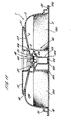
- the overall shape of the cartridge 1 is generally circular or disc-shaped with the diameter of the cartridge 1 being significantly greater than its height.
- a major axis X passes through the centre of the outer member as shown in Figure 1.
- the overall diameter of the outer member 2 is 74.5 mm ⁇ 6mm and the overall height is 16 mm ⁇ 3mm.
- the volume of the cartridge 1 when assembled is 30.2 ml ⁇ 20%.
- the outer member 2 generally comprises a bowl-shaped shell 10 having a curved annular wall 13, a closed top 11 and an open bottom 12.
- the diameter of the outer member 2 is smaller at the top 11 compared to the diameter at the bottom 12, resulting from a flaring of the annular wall 13 as one traverses from the closed top 11 to the open bottom 12.
- the annular wall 13 and closed bottom 11 together define a receptacle having an interior 34.
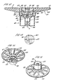
- a hollow inwardly directed cylindrical extension 18 is provided in the closed top 11 centred on the major axis X.
- the cylindrical extension 18 comprises a stepped profile having first, second and third portions 19, 20 and 21.
- the first portion 19 is right circular cylindrical.
- the second portion 20 is frusto-conical in shape and is inwardly tapered.
- the third portion 21 is another right circular cylinder and is closed off by a lower face 31.
- the diameter of the first, second and third portion 19, 20 and 21 incrementally decreases such that the diameter of the cylindrical extension 18 decreases as one traverses from the top 11 to the closed lower face 31 of the cylindrical extension 18.
- a generally horizontal shoulder 32 is formed on the cylindrical extension 18 at the junction between the second and third portions 20 and 21.
- An outwardly extending shoulder 33 is formed in the outer member 2 towards the bottom 12.
- the outwardly extending shoulder 33 forms a secondary wall 15 co-axial with the annular wall 13 so as to define an annular track forming a manifold 16 between the secondary wall 15 and the annular wall 13.
- the manifold 16 passes around the circumference of the outer member 2.
- a series of slots 17 are provided in the annular wall 13 level with the manifold 16 to provide gas and liquid communication between the manifold 16 and the interior 34 of the outer member 2. As shown in Figure 3, the slots 17 comprise vertical slits in the annular wall 13. Between 20 and 40 slots are provided. In the embodiment shown thirty-seven slots 17 are provided generally equi-spaced around the circumference of the manifold 16.
- the slots 17 are preferably between 1.4 and 1.8 mm in length. Typically the length of each slot is 1.6 mm representing 10% of the overall height of the outer member 2.
- the width of each slot is between 0.25 and 0.35 mm. Typically, the width of each slot is 0.3 mm. The width of the slots 17 is sufficiently narrow to prevent the beverage ingredients passing therethrough into the manifold 16 either during storage or in use.
- An inlet chamber 26 is formed in the outer member 2 at the periphery of the outer member 2.
- a cylindrical wall 27 is provided, as most clearly shown in Figure 5, which defines the inlet chamber 26 within, and partitions the inlet chamber 26 from, the interior 34 of the outer member 2.
- the cylindrical wall 27 has a closed upper face 28 which is formed on a plane perpendicular to the major axis X and an open lower end 29 co-planar with the bottom 12 of the outer member 2.
- the inlet chamber 26 communicates with the manifold 16 via two slots 30 as shown in Figure 1. Alternatively, between one and four slots may be used to communicate between the manifold 16 and the inlet chamber 26.
- a lower end of the outwardly extending shoulder 33 is provided with an outwardly extending flange 35 which extends perpendicularly to the major axis X.
- the flange 35 has a width of between 2 and 4 mm.
- a portion of the flange 35 is enlarged to form a handle 24 by which the outer member 2 may be held.
- the handle 24 is provided with an upturned rim 25 to improve grip.
- the outer member 2 is formed as a single integral piece from high density polyethylene, polypropylene, polystyrene, polyester, or a laminate of two or more of these materials.
- a suitable polypropylene is the range of polymers available from DSM UK Limited (Redditch, United Kingdom).
- the outer member may be opaque, transparent or translucent.
- the manufacturing process may be injection moulding.
- the inner member 3 as shown in Figures 7 to 10, comprises an annular frame 41 and a downwardly extending cylindrical funnel 40.
- a major axis X passes through the centre of the inner member 3 as shown in Figure 7.
- the annular frame 41 comprises an outer rim 51 and an inner hub 52 joined by ten equi-spaced radial spokes 53.
- the inner hub 52 is integral with and extends from the cylindrical funnel 40.
- Filtration apertures 55 are formed in the annular frame 41 between the radial spokes 53.
- a filter 4 is disposed on the annular frame 41 so as to cover the filtration apertures 55.
- the filter is preferably made from a material with a high wet strength, for example a non-woven fibre material of polyester.
- Other materials which may be used include a water-impermeable cellulosic material, such as a cellulosic material comprising woven paper fibres.
- the woven paper fibres may be admixed with fibres of polypropylene, polyvinyl chloride and/or polyethylene. The incorporation of these plastic materials into the cellulosic material renders the cellulosic material heat-sealable.
- the filter 4 may also be treated or coated with a material which is activated by heat and/or pressure so that it can be sealed to the annular frame 41 in this way.
- the inner hub 52 is located at a lower position than the outer rim 51, resulting in the annular frame 41 having a sloping lower profile.
- each spoke 53 is provided with an upstanding web 54 which divides a void space above the annular frame 41 into a plurality of passages 57.
- Each passage 57 is bounded on either side by a web 54 and on a lower face by the filter 4.
- the passages 57 extend from the outer rim 51 downwardly towards, and open into, the cylindrical funnel 40 at openings 56 defined by the inner extremities of the webs 54.
- the cylindrical funnel 40 comprises an outer tube 42 surrounding an inner discharge spout 43.
- the outer tube 42 forms the exterior of the cylindrical funnel 40.
- the discharge spout 43 is joined to the outer tube 42 at an upper end of the discharge spout 43 by means of an annular flange 47.
- the discharge spout 43 comprises an inlet 45 at an upper end which communicates with the openings 56 of the passages 57 and an outlet 44 at a lower end through which the prepared beverage is discharged into a cup or other receptacle.
- the discharge spout 43 comprises a frusto-conical portion 48 at an upper end and a cylindrical portion 58 at a lower end.
- the cylindrical portion 58 may have a slight taper such that it narrows towards the outlet 44.
- the frusto-conical portion 48 helps to channel beverage from the passages 57 down towards the outlet 44 without inducing turbulence to the beverage.
- An upper surface of the frusto-conical portion 48 is provided with four support webs 49 equi-spaced around the circumference of the cylindrical funnel 40.
- the support webs 49 define channels 50 therebetween.
- the upper edges of the support webs 49 are level with one another and perpendicular to the major axis X.
- the inner member 3 may be formed as a single integral piece from polypropylene or a similar material as described above and by injection moulding in the same manner as the outer member 2.
- the inner member 3 and/or the outer member 2 may be made from a biodegradable polymer.
- suitable materials include degradable polyethylene (for example, SPITEK supplied by Symphony Environmental, Borehamwood, United Kingdom), biodegradable polyester amide (for example, BAK 1095 supplied by Symphony Environmental), poly lactic acids (PLA supplied by Cargil, Minnesota, USA), starch-based polymers, cellulose derivatives and polypeptides.
- the laminate 5 is formed from two layers, a first layer of aluminium and a second layer of cast polypropylene.
- the aluminium layer is between 0.02 and 0.07 mm in thickness.
- the cast polypropylene layer is between 0.025 and 0.065 mm in thickness.
- the aluminium layer is 0.06 mm and the polypropylene layer is 0.025 mm thick.
- This laminate is particularly advantageous as it has a high resistance to curling during assembly. As a result the laminate 5 may be pre-cut to the correct size and shape and subsequently transferred to the assembly station on the production line without undergoing distortion. Consequently, the laminate 5 is particularly well suited to welding.
- Other laminate materials may be used including PET/Aluminium/PP, PE/EVOH/PP, PET/metallised/PP and Aluminium/PP laminates. Roll laminate stock may be used instead of die cut stock.
- the cartridge 1 may be closed by a rigid or semi-rigid lid instead of a flexible laminate.
- the outer member 2 is orientated with the open bottom 12 directed upwards.
- the inner member 3 is then inserted into the outer member 2 with the outer rim 51 being received as a loose fit in an axial extension 14 at top 11 of the cartridge 1.
- the cylindrical extension 18 of the outer member 2 is at the same time received in the upper portion of the cylindrical funnel 40 of the inner member 3.
- the third portion 21 of the cylindrical extension 18 is seated inside the cylindrical funnel 40 with the closed lower face 31 of the cylindrical extension 18 bearing against the support webs 49 of the inner member 3.
- the filter 4 is then placed over the inner member 3 such that the filter material contacts the annular rim 51.
- An ultrasonic welding process is then used to join the filter 4 to the inner member 3 and at the same time, and in the same process step, the inner member 3 to the outer member 2.
- the inner member 3 and filter 4 are welded around the outer rim 51.
- the inner member 3 and outer member 2 are joined by means of weld lines around the outer rim 51 and also the upper edges of the webs 54
- the outer member 2 and inner member 3 when joined together define a void space 130 in the interior 120 below the annular flange 41 and exterior the cylindrical funnel 40 which forms a filtration chamber.
- the filtration chamber 130 and passages 57 above the annular frame 41 are separated by the filter paper 4.
- the filtration chamber 130 contains the one or more beverage ingredients 200.
- the one or more beverage ingredients are packed into the filtration chamber 130.
- the ingredient is typically roast and ground coffee or leaf tea.
- the density of packing of the beverage ingredients in the filtration chamber 130 can be varied as desired.
- the filtration chamber contains between 5.0 and 10.2 grams of roast and ground coffee in a filtration bed of thickness of typically 5 to 14 mm.
- the interior 120 may contain one or more bodies, such as spheres, which are freely movable within the interior 120 to aid mixing by inducing turbulence and breaking down deposits of beverage ingredients during discharge of the beverage.
- the laminate 5 is then affixed to the outer member 2 by forming a weld 126 around the periphery of the laminate 5 to join the laminate 5 to the lower surface of the outwardly extending flange 35.
- the weld 126 is extended to seal the laminate 5 against the lower edge of the cylindrical wall 27 of the inlet chamber 26.
- a weld 125 is formed between the laminate 5 and the lower edge of the outer tube 42 of the cylindrical funnel 40.
- the laminate 5 forms the lower wall of the filtration chamber 130 and also seals the inlet chamber 26 and cylindrical funnel 40.
- a small gap 123 exists prior to dispensation between the laminate 5 and the lower edge of the discharge spout 43.
- a variety of welding methods may be used, such as heat and ultrasonic welding, depending on the material characteristics of the laminate 5.
- the inner member 3 spans between the outer member 2 and the laminate 5.
- the inner member 3 is formed from a material of relative rigidity, such as polypropylene.
- the inner member 3 forms a load-bearing member that acts to keep the laminate 5 and outer member 2 spaced apart when the cartridge 1 is compressed. It is preferred that the cartridge 1 is subjected to a compressive load of between 130 and 280N in use. The compressive force acts to prevent the cartridge failing under internal pressurisation and also serves to squeeze the inner member 3 and outer member 2 together. This ensures that the internal dimensions of passageways and apertures in the cartridge 1 are fixed and unable to change during pressurisation of the cartridge 1.
- the cartridge 1 To use the cartridge 1 it is first inserted into a beverage preparation machine (which will be described in further detail below) and the inlet 121 and outlet 122 are opened by piercing members of the beverage preparation machine which perforate and fold back the laminate 5.
- An aqueous medium typically water
- An aqueous medium typically water
- the water is at the same time forced upwardly through the beverage ingredients.
- the beverage formed by passage of the water through the beverage ingredients passes through the filter 4 and filtration apertures 55 into the passages 57 lying above the annular frame 41.
- the sealing of the filter 4 onto the spokes 53 and the welding of the rim 51 with the outer member 2 ensures that there are no short-circuits and all the beverage has to pass through the filter 4.
- the beverage then flows downwardly along the radial passages 57 formed between the webs 54 and through the openings 56 and into the cylindrical funnel 40.
- the beverage passes along the channels 50 between the support webs 47 and down the discharge spout 43 to the outlet 44 where the beverage is discharged into a receptacle such as a cup.
- the beverage preparation machine comprises an air purge facility, wherein compressed air is forced through the cartridge 1 at the end of the operating cycle to flush out the remaining beverage into the receptacle.
- a second version of cartridge 1 is shown in Figures 12 to 18.
- the second version of the cartridge 1 is particularly designed for use in dispensing espresso-style products such as roast and ground coffee where it is desirable to produce a beverage having a froth of tiny bubbles known as a crema.
- Many of the features of the second version of the cartridge 1 are the same as in the first version and like numerals have been used to reference like features. In the following description the differences between the first and second versions will be discussed. Common features which function in the same manner will not be discussed in detail.
- the outer member 2 is of the same construction as in the first version of cartridge 1 and as shown in Figures 1 to 6.
- the annular frame 41 of the inner member 3 is the same as in the first version. Also, a filter 4 is disposed on the annular frame 41 so as to cover the filtration apertures 55.
- the outer tube 42 of the cylindrical funnel 40 is also as before.
- the discharge spout 43 is provided with a partition 65 which extends part way up the discharge spout 43 from the outlet 44. The partition 65 helps to prevent the beverage spraying and/or splashing as it exits the discharge spout 43.
- the profile of the discharge spout 43 is also different and comprises a stepped profile with a distinct dog-leg 66 near an upper end of the tube 43.
- a rim 67 is provided upstanding from the annular flange 47 joining the outer tube 42 to the discharge spout 43.
- the rim 67 surrounds the inlet 45 to the discharge spout 43 and defines an annular channel 69 between the rim 67 and the upper portion of the outer tube 42.
- the rim 67 is provided with an inwardly directed shoulder 68.
- an aperture 70 is provided in the form of a slot which extends from an upper edge of rim 67 to a point marginally below the level of the shoulder 68 as most clearly shown in Figures 12 and 13.
- the slot has a width of 0.64 mm.
- An air inlet 71 is provided in annular flange 47 circumferentially aligned with the aperture 70 as shown in Figures 16 and 17.
- the air inlet 71 comprises an aperture passing through the flange 47 so as to provide communication between a point above the flange 47 and the void space below the flange 47 between the outer tube 42 and discharge spout 43.
- the air inlet 71 comprises an upper frusto-conical portion 73 and a lower cylindrical portion 72.
- the air inlet 71 is typically formed by a mould tool such as a pin. The tapered profile of the air inlet 71 allows the mould tool to be more easily removed from the moulded component.
- the wall of the outer tube 42 in the vicinity of the air inlet 71 is shaped to form a chute 75 leading from the air inlet 71 to the inlet 45 of the discharge spout 43.
- a canted shoulder 74 is formed between the air inlet 71 and the chute 75 to ensure that the jet of beverage issuing from the slot 70 does not immediately foul on the upper surface of the flange 47 in the immediate vicinity of the air inlet 71.
- the assembly procedure for the second version of cartridge 1 is similar to the assembly of the first version. However, there are certain differences. As shown in Figure 18, the third portion 21 of the cylindrical extension 18 is seated inside the support rim 67 rather than against support webs. The shoulder 32 of the cylindrical extension 18 between the second portion 20 and third portion 21 bears against the upper edge of the support rim 67 of the inner member 3. An interface zone 124 is thus formed between the inner member 3 and the outer member 2 comprising a face seal between the cylindrical extension 18 and the support rim 67 which extends around nearly the whole circumference of the cartridge 1.
- the seal between the cylindrical extension 18 and the support rim 67 is not fluid-tight though since the slot 70 in the support rim 67 extends through the support rim 67 and downwardly to a point marginally below the shoulder 68. Consequently the interface fit between the cylindrical extension 18 and the support rim 67 transforms the slot 70 into an aperture 128, as most clearly shown in Figure 18, providing gas and liquid communication between the annular channel 69 and the discharge spout 43.
- the aperture is typically 0.64 mm wide by 0.69 mm long.
- Operation of the second version of cartridge 1 to dispense a beverage is similar to the operation of the first version but with certain differences.
- Beverage in the radial passages 57 flows downwardly along the passages 57 formed between the webs 54 and through the openings 56 and into the annular channel 69 of the cylindrical funnel 40. From the annular channel 69 the beverage is forced under pressure through the aperture 128 by the back pressure of beverage collecting in the filtration chamber 130 and passages 57. The beverage is thus forced through aperture 128 as a jet and into an expansion chamber formed by the upper end of the discharge spout 43. As shown in Figure 18, the jet of beverage passes directly over the air inlet 71. As the beverage enters the discharge spout 43 the pressure of the beverage jet drops.
- the aperture 128 and the air inlet 71 together form an eductor which acts to entrain air into the beverage.
- Flow of beverage into the eductor should be kept as smooth as possible to reduce pressure losses.
- the walls of the eductor should be made concave to reduce losses due to 'wall effect' friction.
- the dimensional tolerance of the aperture 128 is small.
- the aperture size is fixed plus or minus 0.02 mm 2 .
- Hairs, fibrils or other surface irregularities can be provided within or at the exit of the eductor to increase the effective cross-sectional area which has been found to increase the degree of air entrainment.
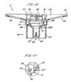
- a third version of cartridge 1 is shown in Figures 19 to 29.
- the third version of the cartridge 1 is particularly designed for use in dispensing soluble products which may be in powdered, liquid, syrup, gel or similar form.
- the soluble product is dissolved by or forms a suspension in, an aqueous medium such as water when the aqueous medium is passed, in use, through the cartridge 1.
- beverages include chocolate, coffee, milk, tea, soup or other rehydratable or aqueous-soluble products.
- the hollow inwardly directed cylindrical extension 18 of the outer member 2 of the third version has a larger overall diameter as shown in Figure 20.
- the diameter of the first portion 19 is typically between 16 and 18 mm compared to 13.2 mm for the outer member 2 of the previous versions.
- the first portion 19 is provided with a convex outer surface 19a, or bulge, as most clearly shown in Figure 20, the function of which will be described below.
- the diameter of the third portions 21 of the cartridges 1 are however the same resulting in the area of the shoulder 32 being greater in this, the third version of the cartridge 1.
- the volume of the cartridge 1 when assembled is 32.5 ml ⁇ 20%.
- the number and positioning of the slots in the lower end of the annular wall 13 is also different. Between 3 and 5 slots are provided. In the embodiment as shown in Figure 23, four slots 36 are provided equi-spaced around the circumference of the manifold 16. The slots 36 are slightly wider than in the previous versions of the cartridge 1 being between 0.35 and 0.45 mm, preferably 0.4 mm wide.
- the construction of the cylindrical funnel 40 of the inner member 3 is the same as in the first version of cartridge 1 with an outer tube 42, discharge spout 45, annular flange 47 and support webs 49 being provided.
- the only difference is that the discharge spout 45 is shaped with an upper frusto-conical section 92 and a lower cylindrical section 93.
- annular frame 41 is replaced by a skirt portion 80 which surrounds the cylindrical funnel 40 and is joined thereto by means of eight radial struts 87 which adjoin the cylindrical funnel 40 at or near the annular flange 47.
- a cylindrical extension 81 of the skirt portion 80 extends upwardly from the struts 87 to define a chamber 90 with an open upper face.
- An upper rim 91 of the cylindrical extension 81 has an in-turned profile as shown in Figure 26.
- An annular wall 82 of the skirt portion 80 extends downwardly from the struts 87 to define an annular channel 86 between the skirt portion 80 and the outer tube 42.
- the annular wall 82 comprises at a lower end an exterior flange 83 which lies perpendicular to the major axis X.
- a rim 84 depends downwardly from a lower surface of the flange 83 and contains five apertures 85 which are circumferentially equi-spaced around the rim 84.
- the rim 84 is provided with a castellated lower profile.
- Apertures 89 are provided between the struts 87 allowing communication between the chamber 90 and the annular channel 86.
- the assembly procedure for the third version of cartridge 1 is similar to the assembly of the first version but with certain differences.
- the outer member 2 and inner member 3 are push-fitted together as shown in Figure 29 and retained by means of a snap-fit arrangement rather than welded together.
- On joining the two members the inwardly directed cylindrical extension 18 is received inside the upper cylindrical extension 81 of the skirt portion 80.
- the inner member 3 is retained in the outer member 2 by frictional interengagement of the convex outer surface 19a of the first portion 19 of the cylindrical extension 18 with the in-turned rim 91 of the upper cylindrical extension 81.
- With the inner member 3 located in the outer member 2 a mixing chamber 134 is defined located exterior to the skirt portion 80.
- the mixing chamber 134 contains the beverage ingredients 200 prior to dispensation.
- the four inlets 36 and the five apertures 85 are staggered circumferentially with respect to one another.
- the radial location of the two parts relative to each other need not be determined or fixed during assembly since the use of four inlets 36 and five apertures 85 ensures that misalignment occurs between the inlets and apertures whatever the relative rotational positioning of the components.
- the one or more beverage ingredients are packed into the mixing chamber 134 of the cartridge.
- the density of packing of the beverage ingredients in the mixing chamber 134 can be varied as desired.
- the laminate 5 is then affixed to the outer member 2 and inner member 3 in the same manner as described above in the previous versions.
- water enters the mixing chamber 134 through the four slots 36 in the same manner as previous versions of the cartridge.
- the water is forced radially inwardly through the mixing chamber and mixes with the beverage ingredients contained therein.
- the product is dissolved or mixed in the water and forms the beverage in the mixing chamber 134 and is then driven though the apertures 85 into the annular channel 86 by back pressure of beverage and water in the mixing chamber 134.
- the circumferential staggering of the four inlet slots 36 and the five apertures 85 ensures that jets of water are not able to pass radially directly from the inlet slots 36 to the apertures 85 without first circulating within the mixing chamber 134. In this way the degree and consistency of dissolution or mixing of the product is significantly increased.
- the beverage is forced upwardly in the annular channel 86, through the apertures 89 between the struts 87 and into the chamber 90.
- the beverage passes from chamber 90 through the inlets 45 between the support webs 49 into the discharge spout 43 and towards the outlet 44 where the beverage is discharged into a receptacle such as a cup.
- the cartridge finds particular application with beverage ingredients in the form of viscous liquids or gels.
- a liquid chocolate ingredient is contained in the cartridge 1 with a viscosity of between 1700 and 3900mPa at ambient temperature and between 5000 and 10000mPa at 0°C and a refractive solids of 67 Brix ⁇ 3.
- liquid coffee is contained in the cartridge 1 with a viscosity of between 70 and 2000mPa at ambient and between 80 and 5000mPa at 0°C where the coffee has a total solids level of between 40 and 70%.
- the liquid coffee ingredient may contain between 0.1 and 2.0% by weight sodium bicarbonate, preferably between 0.5 and 1.0% by weight.
- the sodium bicarbonate acts to maintain the pH level of the coffee at or below 4.8 enabling a shelf-life for coffee-filled cartridges of up to 12 months.
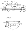
- a fourth version of cartridge 1 is shown in Figures 30 to 34.
- the fourth version of the cartridge 1 is particularly designed for use in dispensing liquid products such as concentrated liquid milk.
- Many of the features of the fourth version of the cartridge 1 are the same as in the previous versions and like numerals have been used to reference like features. In the following description the differences between the fourth and previous versions will be discussed. Common features which function in the same manner will not be discussed in detail.
- the outer member 2 is the same as in the third version of cartridge 1 and as shown in Figures 19 to 23.
- the cylindrical funnel 40 of the inner member 3 is similar to that shown in the second version of cartridge 1 but with certain differences.
- the discharge spout 43 is shaped with an upper frusto-conical section 106 and a lower cylindrical section 107.
- Three axial ribs 105 are provided on the inner surface of the discharge spout 43 to direct the dispensed beverage downwards towards the outlet 44 and prevent the discharged beverage from spinning within the spout. Consequently, the ribs 105 act as baffles.
- an air inlet 71 is provided through the annular flange 47. However, the chute 75 beneath the air inlet 71 is more elongated than in the second version.
- a skirt portion 80 is provided similar to that shown in the third version of the cartridge 1 described above. Between 5 and 12 apertures 85 are provided in the rim 84. Typically ten apertures are provided rather than the five provided in the third version of cartridge 1.
- annular bowl 100 is provided extending from and integral with the flange 83 of the skirt portion 80.
- the annular bowl 100 comprises a flared body 101 with an open upper mouth 104 which is directed upwards.
- feed apertures 103 shown in Figures 30 and 31 are located in the body 101 at or near the lower end of the bowl 100 where it joins the skirt portion 80.
- the feed apertures are equi-spaced around the circumference of the bowl 100.
- the laminate 5 is of the type described above in the previous embodiments.
- the assembly procedure for the fourth version of cartridge 1 is the same as that for the third version.
- Operation of the fourth version of cartridge is similar to that of the third version.
- the water enters the cartridge 1 and the mixing chamber 134 in the same manner as before. There the water mixes with and dilutes the liquid product which is then forced out below the bowl 100 and through the apertures 85 towards the outlet 44 as described above.
- the proportion of the liquid product initially contained within the annular bowl 100 as shown in Figure 34 is not subject to immediate dilution by the water entering the mixing chamber 134. Rather, the diluted liquid product in the lower part of the mixing chamber 134 will tend to exit through apertures 85 rather than be forced up and into the annular bowl 100 through upper mouth 104.
- the liquid product in the annular bowl 100 will remain relatively concentrated during the initial stages of the operating cycle compared to the product in the lower part of the mixing chamber 134.
- the liquid product in the annular bowl 100 drips through the feed apertures 103 under gravity into the stream of product exiting the mixing chamber 134 through the apertures 85 and below the bowl 100.
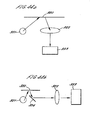
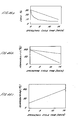
- the annular bowl 100 acts to even out the concentration of the diluted liquid product entering the cylindrical funnel 40 by holding back a proportion of the concentrated liquid product and releasing it into the exiting liquid stream flow path steadily throughout the operating cycle as illustrated in Figure 46a where the concentration of the milk measured as a percentage of the total solids present is shown during an operating cycle of approximately 15 seconds.
- Line a illustrates the concentration profile with the bowl 100 whilst line b illustrates a cartridge without the bowl 100.
- the initial concentration of the milk is typically 30-35% SS and at the end of the cycle 10% SS. This results in a dilution ratio of around 3 to 1, although dilution ratios of between 1 to 1 and 6 to 1 are possible with the present invention.
- concentrations may vary. For example for liquid chocolate the initial concentration is approximately 67% SS and at the end of the cycle 12-15% SS.
- a dilution ratio ratio of aqueous medium to beverage ingredient in dispensed beverage
- dilution ratios ratio of between 2 to 1 and 10 to 1 are possible with the present invention.
- the initial concentration is between 40-67% and the concentration at the end of dispense 1-2% SS.
- a dilution ratio of between 20 to 1 and 70 to 1, although dilution ratios of between 10 to 1 and 100 to 1 are possible with the present invention.
- the beverage is forced under pressure through the aperture 128 by the back pressure of beverage collecting in the filtration chamber 134 and chamber 90.
- the beverage is thus forced through aperture 128 as a jet and into an expansion chamber formed by the upper end of the discharge spout 43.
- the jet of beverage passes directly over the air inlet 71.
- the pressure of the beverage jet drops.
- air is entrained into the beverage stream in the form of a multitude of small air bubbles as the air is drawn up through the air inlet 71.
- the jet of beverage issuing from the aperture 128 is funnelled downwards to the outlet 44 where the beverage is discharged into a receptacle such as a cup where the air bubbles form the desired frothy appearance.
- the inner member 3, outer member 2, laminate 5 and filter 4 can all be readily sterilised due to the components being separable and not individually comprising tortuous passageways or narrow crevices. Rather, it is only after conjoining the components, after sterilisation, that the necessary passageways are formed. This is particularly important where the beverage ingredient is a dairy-based product such as liquid milk concentrate.
- the fourth embodiment of beverage cartridge is particularly advantageous for dispensing a concentrated dairy-based liquid product such as liquid milk.
- a concentrated dairy-based liquid product such as liquid milk.
- powdered milk products have been provided in the form of sachets for adding to a pre-prepared beverage.
- a cappuccino-style beverage it is necessary to foam the milk. This has been achieved previously by passing steam through a liquid milk product.
- steam passes through a liquid milk product.
- this necessitates the provision of a steam supply which increases the cost and complexity of the machine used to dispense the beverage.
- the use of steam also increases the risk of injury during operation of the cartridge.
- the present invention provides for a beverage cartridge having a concentrated dairy-based liquid product therein.
- Fresh semi-skimmed milk contains approximately 1.6% fat and 10% total solids.
- the concentrated liquid milk preparations of the present invention contain between 0.1 and 12% fat and 25 to 40% total solids. In a typical example, the preparation contains 4% fat and 30% total solids.
- the concentrated milk preparations are suitable for foaming using a low pressure preparation machine as will be described below. In particular, foaming of the milk is achieved at pressures below 2 bar, preferably approximately 1.5 bar using the cartridge of the fourth embodiment described above.
- the foaming of the concentrated milk is particularly advantageous for beverages such as cappuccinos and milk shakes.
- the passing of the milk through the aperture 128 and over the air inlet 71 and the optional use of the bowl 100 enables foaming levels of greater than 40%, preferably greater than 70% for milk.
- foaming levels of greater than 40% preferably greater than 70% for milk.
- For liquid chocolate foaming levels of greater than 70% are possible.
- For liquid coffee foaming levels of greater than 70% are possible.
- the foamability of the milk is enhanced by the provision of the bowl 100 as can be seen in Figure 46b.
- the foamability of the milk dispensed with the bowl 100 present (line a) is greater than that of milk dispensed without the bowl present (line b).
- the foamability of the milk is positively correlated to the concentration of the milk and as shown in Figure 46a the bowl 100 maintains a higher concentration of the milk a larger part of the operating cycle.
- foamability of the milk is positively correlated to temperature of the aqueous medium as shown in Figure 46c.
- the bowl 100 is advantageous since more of the milk remains in the cartridge until near the end of the operating cycle when the aqueous medium is at its hottest. This again improves foamability.
- the cartridge of the fourth embodiment is also advantageous in dispensing liquid coffee products.
- beverage cartridge of the present invention advantageously provide an improved consistency of the brewed beverage when compared to prior art cartridges.
- Table 1 shows the results of brew yields for twenty samples each of cartridges A and B containing roast and ground coffee.
- Cartridge A is a beverage cartridge according to the first embodiment of the present invention.
- Cartridge B is a prior art beverage cartridge as described in the applicant's document WO01/58786.
- % Yield (%SS * Brew Volume (g))/ (100 * Coffee Weight (g))
- the materials of the cartridges described above may be provided with a barrier coating to improve their resistance to oxygen and/or moisture and/or other contaminant ingress.
- the barrier coating may also improve the resistance to leakage of the beverage ingredients from within the cartridges and/or reduce the degree of leaching of extractibles from the cartridge materials which might adversely affect the beverage ingredients.
- the barrier coating may be of a material selected from the group of PET, Polyamide, EVOH, PVDC or a metallised material.
- the barrier coating may be applied by a number of mechanisms including but not limited to vapour deposition, vacuum deposition, plasma coating, co-extrusion, in-mould labelling and two/multi-stage moulding.
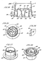
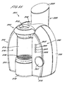
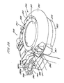
- a beverage preparation machine 201 for use with the above described beverage cartridges is shown in Figures 35 to 45.
- the beverage preparation machine 201 generally comprises a housing 210 containing a water tank 220, a water heater 225, a water pump 230, an air compressor 235, a control processor, a user interface 240 and a cartridge head 250.
- the cartridge head 250 in turn generally comprises a cartridge holder 251 for holding, in use, the beverage cartridge 1, cartridge recognition means 252 and inlet and outlet piercers 253, 254 for forming, in use, the inlet 121 and the outlet 122 in the beverage cartridge 1.
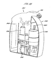
- the housing 210 contains and holds in position the other components of the machine 201.
- the housing 210 preferably made in whole or in part from a robust plastics material such as ABS.
- the housing 210 can be made in whole or in part from a metallic material such as stainless steel or aluminium.
- the housing 210 is preferably comprises a clam-shell design having a front half 211 and a rear half 212 which allow access during assembly for fitting of the machine 201 components and can afterwards be joined together to define an interior 213 of the housing 210.
- the rear half 212 provides a recess 214 for the attachment of the water tank 220.
- the housing 210 is formed with means, such as detents, abutments, bosses and threaded portions, for retaining the components of the machine 201 in position without the need for a separate chassis. This reduces the overall cost and weight of the machine 201.
- a base 215 of the housing 210 is preferably provided with feet for standing the machine thereon in a stable manner. Alternatively, the base 215 itself may have a shape forming a stable support.
- the front half 211 of the housing 210 comprises a dispense station 270 where dispensation of the beverage takes place.
- the dispense station 270 comprises a receptacle stand 271 having a hollow interior forming a drip tray 272.
- An upper surface 273 of the receptacle stand is provided with a grill 274 on which the receptacle is positioned.
- the drip tray 272 is removable from the housing 210 to ease emptying of the collected water.
- a recess 275 is formed in the front half of the housing 210 above the receptacle stand 271 to accommodate the dimensions of the receptacle.
- the cartridge head 250 is located towards the top of the housing 210 above the receptacle stand as shown in Figures 35 and 36.
- the height of the grill 274 relative to the cartridge head 250 can be adjusted to accommodate different sizes of receptacle. It is preferred that the receptacle is as close to the cartridge head 250 as possible, whilst still allowing the receptacle to be inserted and withdrawn from the dispense station 270, so as to minimise the height that the dispensed beverage has to descend before contacting the receptacle. This acts to minimise spraying and splashing of the beverage and minimise loss of entrained air bubbles where these are present.
- receptacles of between 70mm and 110 mm in height can be inserted between the grill 274 and cartridge head 250.
- the machine user interface 240 is located on the front of the housing 210 and comprises a start/stop button 241, and a plurality of status indicators 243-246.
- the status indicators 243-246 preferably include a light emitting diode (LED) 243 to indicate readiness of the machine 201, a LED 244 to indicate if an error has occurred in the machine 201 operation, and one or more LEDs 245-256 to indicate whether the machine 201 is operating in manual or automatic modes.
- the LEDs 243-246 may be controlled to illuminate at a constant intensity, to flash intermittently, or both depending on the status of the machine 201.
- the LEDs 243-246 may have a variety of colours including green, red and yellow.
- the start/stop button 241 controls commencement of the operating cycle and is a manually operated push-button, switch or similar.
- a volume adjustment control may be provided to allow a user of the machine 201 to manually adjust the volume of the delivered beverage without altering the other operating characteristics.
- the volume adjustment control allows an adjustment in volume of plus or minus 20%.
- the volume adjustment control may be a rotary knob, a linear slider, a digital readout with increment and decrement buttons, or similar. More typically, volume is controlled by a user operating the start/stop button 241.
- a manual power switch (not shown) may be provided on the machine 201.
- power supply can be controlled simply by insertion or removal or the power supply plug from the mains power supply.
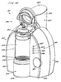
- the water tank 220 is located to the rear of the housing 210 and is connected to the rear half 212 of the housing 210.
- the water tank 220 comprises a generally cylindrical body 221 which may be right circular or a frustum as desired for aesthetic reasons.
- the tank comprises an inlet for filling the tank with water which is closed off in use by a manually removable lid 222.
- An outlet is provided towards a lower end of the tank which communicates with the water pump 230.
- the water tank 220 may be made from a transparent or translucent material to allow a consumer to view the quantity of water remaining in the tank. Alternatively, the water tank 220 may be made from an opaque material but have provided a viewing window therein.
- the water tank 220 may be provided with a low level sensor which prevents operation of the water pump 230 and optionally triggers a warning indicator, such as an LED, when the water level in the tank descends to a preselected level.
- the water tank 220 preferably has an internal capacity of approximately 1.5 litres.
- the water pump 230 is operatively connected between the water tank 220 and the water heater 225 as shown schematically in Figure 43 and is controlled by the control processor.
- the pump provides a maximum flow rate of 900 ml/min of water at a maximum pressure of 2.5 bar. Preferably, in normal use, the pressure will be limited to 2 bar.
- the flow rate of water through the machine 201 can be controlled by the control processor to be a percentage of the maximum flow rate of the pump by cycle chopping the electrical supply to the pump.
- the pump can be driven at any of 10%, 20%, 30%, 40%, 50%, 60%, 70%, 80%, 90% or 100% of the maximum rated flow rate.
- the accuracy of the volume of water pumped is preferably + or - 5% leading to a + or - 5% accuracy in the final volume of the dispensed beverage.
- a suitable pump is the Evolution EP8 pump produced by Ulka S.r.l. (Pavia, Italy).
- a volumetric flow sensor (not shown) is preferably provided in the flow line either upstream or downstream of the water pump 230. Preferably, the volumetric flow sensor is a rotary sensor.
- the water heater 225 is located in the interior of the housing 210.
- the heater 225 has a power rating of 1550 W and is able to heat water received from the water pump 230 from a starting temperature of approximately 20 °C to an operating temperature of around 85 °C in under 1 minute.
- the dwell time between the end of one operating cycle and the heater 225 being able to commence a subsequent operating cycle is less than 10 seconds.
- the heater maintains the selected temperature to within + or - 2 °C during the operating cycle.
- the water for the operating cycle may be delivered to the cartridge head 250 at 83 °C or 93 °C.
- the heater 225 is able to quickly adjust the delivery temperature to either 83 °C or 93 °C from a nominal water temperature of 85 °C.
- the heater 225 comprises an over-temperature cut-off which shuts off the heater if the temperature exceeds 98 °C.
- Water output from the heater 225 is fed to the cartridge head 250 and cartridge 1 by means of a three-way valve. If the pressure of the water flow is acceptable the water is passed to the cartridge 1. If the pressure is below or above predetermined limits then the water is diverted by means of the three-way valve into the drip tray recovery receptacle 270.
- the air compressor 235 is operatively connected to the cartridge head 250 by means of a one-way valve and controlled by the control processor.
- the air compressor 235 provides a maximum flow rate of air of 500 ml/min at 1.0 bar. In use a working volume of 35 ml is pressurised to 2.0 bar.
- the air compressor 235 can produce two flow rates: a fast (or maximum) flow rate and a slow flow rate.
- the control processor of the beverage preparation machine 201 comprises a processing module and a memory.
- the control processor is operatively connected to, and controls operation of, the water heater 225, water pump 230, air compressor 235 and user interface 240.
- the memory of the control processor includes one or more variables for one or more operational parameters for the beverage preparation machine 201.
- the operational parameters are the temperature of the water passed through the beverage cartridge 1 during the operating stage, the speed of charging the beverage cartridge 1, the presence or otherwise of a soak step, the total dispensed volume of the beverage, the flow rate of the water during the discharge stage, and the flow rate and period of the purge stage.
- the variables for the operational parameters are stored in the memory.
- the cartridge 1 comprises a code provided on or in the cartridge 1 representing the operational parameters required for optimal dispensation of the beverage in that cartridge 1.
- the code is in binary format and comprises a plurality of data bits corresponding to the variables stored in the control processor memory. Table 3 illustrates how 13 bits of data can be used to represent the necessary variables for the operational parameters described above.
- the code on or in the cartridge 1 will normally comprises one or more extra data bits for error checking.
- a 16 bit code is provided.
- a cartridge 1 bearing the code "1000100011110” would have the following operational parameters: 10 Water temperature of 83 °C 00 Fast charge with soak 1000 Dispensed drink volume of 150ml 111 Flow rate equals 100% 10 Fast air flow purge/short period.
- the memory of the control processor does not store operational instructions for beverage cartridges based on the cartridge type, i.e. instructions for a coffee cartridge, instructions for a chocolate cartridge, instructions for a tea cartridge etc. Instead the memory of the control processor stores variables for adjusting the individual operational parameters of the operating cycle.
- Prior coding solutions relying on storing instructions by cartridge type rather than by individual parameters are unsuited to such subtle differences in operating cycles for similar beverage types because they quickly consume the available storage space in the coding medium and control processor.
- the coding method of the present invention allows for new beverage cartridge types to be used in pre-existing beverage preparation machines even where the operational parameters for the operating cycle for the new beverage cartridge 1 are only decided upon after sale of the beverage preparation machine 201. This is because the control processor of the beverage preparation machine 201 does not need to recognise that the beverage is of a new type. Rather the operational parameters of the operating cycle are set without direct reference to the beverage type.
- the coding method of the present invention provides excellent backward compatibility of the beverage preparation machines for new beverage types.
- the manufacturer is restricted to dispensing a new beverage type using one of the pre-existing dispensation cycles as determined by the in-market machines.
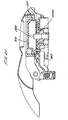
- the cartridge head 250 is shown in Figures 39 to 42.
- the cartridge holder 251 of the cartridge head 250 comprises a fixed lower part 255, a rotatable upper part 256 and a pivotable cartridge mount 257 positioned inbetween the fixed lower part 255 and the rotatable upper part 256.
- the upper part 256, lower part 255 and cartridge mount 257 are rotated about a common hinge axis 258.
- Figures 39 to 42 show the cartridge holder 251 with some components of the machine 201 omitted for clarity.
- the rotatable upper part 256 and pivotable cartridge mount 257 are moved relative to the fixed lower part 255 by means of a clamping mechanism 280.
- the clamping mechanism 280 comprises a clamping lever having first and second members or parts 281 and 282.
- the first part 281 of the clamping lever comprises a U-shaped arm which is pivotably mounted to the upper part 256 at two first pivot points 283, one on each side of the cartridge holder 251.
- the second part of the clamping lever comprises two over-centre arms 282, one on each side of the cartridge holder 251 which are each pivotably mounted to the upper part 256 at a second pivot point 285 located on the hinge axis 258 coupling the upper part 256 to the fixed lower part 255.
- Each over-centre arm 282 is a reciprocal member comprising a cylinder 282a, a stem 282b and a resilient sleeve 282c.
- the cylinder 282a has an internal bore and is rotatably mounted at one end at the hinge axis 258. A first end of the stem 282b is slidingly received in the bore of the cylinder 282a.
- the opposite end of the stem 282b is rotatably mounted to the U-shaped arm 281 at a third pivot point 286.
- the third pivot points 286 are unconnected to, and freely moveable relative to, the upper part 256 and lower part 255.
- the resilient sleeve 282c is mounted externally on the stem 282b and extends, in use, between abutment surfaces on the cylinder 282a and stem 282b.
- the resilient sleeve 282c accommodates shortening of the over-centre arm 282 but biases the over-centre arm 282 into an extended configuration. Movement of the third pivot points 286 towards and away from the hinge axis 258 is thus possible by relative movement of the stems 282b in the cylinders 282a.
- the resilient sleeves 282c are preferably formed from silicone.
- the U-shaped arm 281 extends around the front of the cartridge holder 251 and comprises two downwardly dependant hook members 287, one on each side of the cartridge holder 251, each comprising a cam surface 288 facing the hinge axis 258.
- the fixed lower part 255 of the cartridge holder 251 is provided with two bosses 259, or detents, located one on each side of the lower part 255 at or near a front edge 260 thereof aligned generally with the hook members 287.
- the U-shaped arm 281 may be formed from a one piece plastics moulding comprising an ergonomic hand grip and the hook members 287 integral to the arm.
- the cartridge mount 257 is rotatably mounted between the upper and lower parts 255, 256 of the cartridge holder 251.
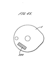
- the mount 257 is provided with a substantially circular recess 290 which receives in use the beverage cartridge 1.
- the recess 290 includes an irregularity 291 for accommodating the handle portion 24 of the beverage cartridge 1 which also acts to prevent rotation of the beverage cartridge 1 in the cartridge holder 251.
- the cartridge mount 257 is sprung relative to the fixed lower part 255 such that in the open position, as shown in Figure 41, the cartridge mount 257 is biased out of contact with the fixed lower part 255 so that the cartridge mount 257 is moved out of contact with the outlet and inlet piercer members 254, 253.
- the cartridge mount 257 is provided with an aperture 292 for receiving therethrough the inlet and outlet piercers 253, 254 and a head 300 of the cartridge recognition means 252 when the cartridge mount 257 is moved into the closed position.
- the upper part 255 comprises a generally circular body 310 housing a circular viewing window 312 through which a consumer can view the beverage cartridge 1 during an operating cycle and also visually confirm whether a cartridge 1 is loaded in the machine 201.
- the viewing window 312 is cup-shaped having a downwardly directed rim 311 which engages and grips the flange 35 of the beverage cartridge 1 against the lower part 256 when the cartridge holder 251 is closed. At the same time the window 312 contacts the closed top 11 of the cartridge 1.
- a wave spring (not shown) is positioned between the viewing window 312 and the circular body 310 to enable the viewing window 312 to move axially relative to the circular body 310 by a small degree. The pressure exerted by the rim 311 on the flange 35 and by the window 312 on the closed top 11 ensures a fluid tight seal between the cartridge 1 and the cartridge holder 251.
- the lower part 255 comprises the inlet and outlet piercers 253, 254 and the head 300 of the cartridge recognition means 252.
- the inlet piercer 253 comprises a hollow needle-like tube 260 having a sharpened end 261 for perforating the laminate 5 of the beverage cartridge 1 in use.
- the inlet piercer 253 is in fluid communication with a water conduit 262 as shown in Figure 42 which passes through the lower part 255 and is connected to an outlet conduit 263 of the water heater 225.
- the outlet piercer 254 is similar in type to the outlet piercer described in the applicant's European patents EP 0 389 141 and EP 0 334 572 and comprises an open ended cylinder 264 of circular or D-shaped cross-section having dimensions larger than the discharge spout 43.
- An arcuate portion 265 of the upper end of the outlet piercer 254 is serrated to pierce and eventually cut the laminate of the beverage cartridge 1.
- the remainder of the upper end is cut back longitudinally of the cylinder at least to the base of the teeth 266 of the serrated portion to fold or pull the cut laminate 5 away from the outlet aperture before the beverage is dispensed therethrough.
- the outlet piercer 254 pierces the laminate 5 externally of the discharge spout 43 and when the cartridge mount 257 is in the closed position, rests in the annulus between the discharge spout 43 and the outer wall 42 of the discharge funnel 40.
- the outlet piercer 254 folds back the cut laminate 105 into the annulus. Thereby both the outlet piercer 254 and the cut laminate 105 are held out of the way of the discharged beverage.
- the outlet piercer 254 is surrounded by a ledge 254a which is raised relative to its surroundings by 0.5mm.
- the outlet piercer 254 is removable from the lower part 255 to enable it to be thoroughly cleaned, for example, in a dishwasher.
- the removable outlet piercer 254 is received in a recess 267 in the lower part 255 where it is seated.
- the inlet piercer 253 and/or the outlet piercer 254 may be made of a metal, such as stainless steel, or from a plastics material.
- the use of plastic cutting elements is enabled by use of a laminate 5 which is able to be punctured and cut by a non-metallic material. Consequently, the piercers 253, 254 can be made less sharp which lowers the risk of injury to the consumer.
- plastic piercing elements are not prone to rust.
- the inlet piercer 253 and the outlet piercer 24 are formed as a single, integral unit which is removable from the lower part 255.
- the upper part 256 of the cartridge holder 251 is movable from an open position in which it is orientated vertically or towards the vertical as shown in Figure 36, to a closed position in which it is orientated substantially horizontally and in interengagement with the fixed lower part 255 and cartridge mount 257.
- the upper part 256 is moved from the open to the closed positions by operation of the clamping lever.
- To close the upper part 256 a user takes hold of the clamping lever by the U-shaped arm 281 and pulls downwards. Consequently, the upper part 256 rotates which first brings the rim 311 of the viewing window 312 into contact with the flange 35 of the beverage cartridge 1 in the cartridge mount 257 and the window 312 itself into contact with the closed top 11 of the cartridge 1.
- the clamping force of the mechanism as moderated by the action of the wave spring ensures a clamping pressure on the cartridge of between 130 and 280N.
- the force is approximately 200N.
- a force less than about 130N does not provide an adequate seal, whilst a force greater than about 280N leads to plastic failure of the components of the cartridge 1.
- the laminate 5 of the cartridge 1 is tensioned as it is brought into contact with the ledge 254a surrounding the outlet piercer 254 which causes the laminate 5 to flex out of plane as the distal end of the outer tube 42 of the cylindrical funnel is moved upwardly by 0.5mm relative to the flange 35.
- This movement also ensures that the great majority of the compressive force applied to the cartridge acts through the central region of the cartridge 1 through the load-bearing inner member 3.
- the cartridge 1 is thus clamped around the flange 35 by means of the rim 311 of the viewing window 312 and firmly clamped between the closed top 11 of the cartridge and the outer tube 42 of the inner member 3 by contact with the viewing window 312 and the ledge 254a.
- These clamping forces help prevent failure of the cartridge 1 during pressurisation and also ensure that the inner member 3 and outer member 2 are fully seated relative to one another and thus that all internal passageways and apertures remain at their intended dimensions even during internal pressurisation.
- An imaginary datum line can be drawn between the first and second pivot points 283, 285 of the cartridge holder 251.
- the third pivot points 286 are located on the side of the datum line nearest the fixed lower part 255.
- the third pivot points 286 of the clamping lever pass through the datum line joining the first and second pivot points 283, 285 to the opposite side of the line, furthest from the fixed lower part 255. Consequently, the U-shaped arm 281 'snaps through' from a first stable position to a second stable position. The snap through action is accommodated by shortening of the over-centre arms 282 and consequential compression of the resilient sleeves 282c.
- the clamping lever thus has a bi-stable operation in that the lever is stable in the open or closed positions but unstable at the point when the third pivot points 286 lie on the imaginary datum line joining the first and second pivot points 283, 285.
- the snap-through action of the clamping lever provides a positive closure mechanism which leads to a definite closure action wherein in the final stages of the clamping lever's rotation, the snap-through action of the U-shaped arm 281 and second arms 284 forces the hook members 287 firmly into engagement with the bosses 259.
- the resilient sleeves 282c provide a resistance to re-opening of the upper part 256 since a minimum force is required to compress the sleeves 282c sufficiently to move the third pivot points 286 back into line with the datum line joining the first and second pivot points 283, 285.
- the interengagement of the hook members 287 and the bosses 259 prevents separation of the upper and lower parts other than by rotation of the clamping lever. This is useful in preventing opening of the cartridge head 250 during operation when the cartridge head 250 is subject to internal pressurisation.
- the cartridge recognition means 252 comprises an optical barcode reader which reads a printed barcode 320 provided on the laminate 5 of the beverage cartridge 1 as shown in Figure 45.
- the barcode 320 is formed from a plurality of bars of contrasting colour. Preferably the bars are black on a white background to maximise the contrast.
- the barcode 320 is not required to conform to a published standard but a standard format for barcodes, such as EAN-13, UPC-A, or Interleaved 2 of 5 may be used.
- the optical barcode reader comprises one or more LEDs 321 to illuminate the barcode 320, a focusing lens 322 to acquire an image of the barcode, a charge coupled device (CCD) 323 for producing an electrical signal representative of the acquired image and support circuitry for the LEDs and CCD.
- CCD charge coupled device
- the space in the lower part for accommodating the barcode reader is limited.
- a mirror or mirrors 324 may be used to reflect the light from the LEDs 321 to a focussing lens which is not located in the lower part 255. Schematic arrangements are shown in Figures 44a and 44b.
- the lower part 255 comprises an aperture 326 which is the same size as the barcode 320 on the beverage cartridge 1. In use the electrical signals produced are decoded by signal processing software and the results forwarded to the control processor.
- the software can recognise whether the read of the barcode contained errors.
- the barcode 320 may be rescanned a number of times before an error message is presented to the consumer. If the machine 201 is unable to read the barcode the consumer is able to use the beverage cartridge 1 to dispense a beverage using a manual mode of operation.
- the cartridge head 250 also includes a cartridge sensor for detecting whether a cartridge is present in the cartridge holder 251.
- the cartridge head 250 also includes a lock sensor which detects whether the cartridge holder 251 is properly closed.
- the lock sensor comprises a micro-switch which is triggered when the cartridge holder 251 is closed and locked.
- the cartridge sensor and lock sensor are connected in series such that the output of both sensors must be satisfactory, i.e. cartridge present and mechanism locked, before the operating cycle can be commenced.
- Operation of the machine 201 comprises insertion of a beverage cartridge 1 into the cartridge head 250, carrying out an operating cycle in which the beverage is dispensed and removal of the cartridge 1 from the machine.
- the operational behaviour of the machine 201 is determined by software embedded in the control processor. Operation of the machine can be described in terms of 'States', wherein the machine 201 will normally exist in a particular State until an event occurs to change the State, a step called a State transition.
- Table 4 shows a State Transition Table which illustrates the States and State transitions for one embodiment of the beverage preparation machine 201.
- the following example illustrates an operating cycle to exemplify the use of the State Transitions by the control processor.
- the machine 201 is initially switched off and with no cartridge 1 inserted in the cartridge head 250.
- the control processor is in State 1.
- the water heater 225 is switched on. Once the temperature reaches 85 °C the control processor transits to State 2. If at any time during State 1 or 2 the cartridge holder 251 is closed the lock sensor will be triggered to send a signal to the control processor indicating that the cartridge holder 251 is properly closed.
- the control processor then interrogates the cartridge sensor by sending a 'readpod' instruction.
- the cartridge sensor returns a signal to the control processor indicating whether a cartridge is in place in the cartridge holder 251.
- control processor transits to State 3 where it remains in a readiness state until the cartridge holder 251 is reopened at which point the control processor transits back to State 2. If a cartridge is present in State 2 then the control processor transits to State 4 and operation is commenced automatically. During States 4 to 9 the water temperature is controlled in the background to remain within the required tolerance range of the desired temperature as set by the operational parameters set by the barcode on the beverage cartridge 1. Once the discharge stage of dispense is completed an air purge is commenced in State 8. Once the air purge is completed the operating cycle is completed and the machine enters to standby mode in State 10. If, during operation, an error occurs then the processor transits to State 11. If a low water level is detected then the processor transits to State 12.
- the cartridge holder 251 is opened as described above to expose the cartridge mount 257.
- the cartridge 1 is then placed on the cartridge mount 257 received within the recess 290 such that the handle 24 of the cartridge is located in the irregularity 291.
- the optical or magnetic barcode 320 of the cartridge 1 is orientated directly above the aperture 326 in the cartridge mount 257.
- the cartridge holder 251 is then closed by operation of the clamping lever as described above.
- the inlet and outlet piercers 253, 254 pierce the laminate 5 of the cartridge 1 to form the cartridge inlet 121 and outlet 122.
- the laminate 5 cut by the outlet piercer 254 is folded up into the annulus surrounding the discharge spout 43.
- the cartridge holder 251 grips the cartridge 1 around the rim 35 between the cartridge mount 257 and the upper part 256 and between the window 311 and the top 11 of the cartridge 1 to form a fluid tight seal of sufficient integrity to withstand the pressures developed during the operating cycle.
- the operating cycle comprises the steps of cartridge recognition and the discharge cycle.
- Cartridge recognition is performed by the optical cartridge recognition means 252 as described above assuming that the outputs from the cartridge sensor and lock sensor are satisfactory. Once the barcode 320 has been decoded the operational parameters of the machine 201 are adjusted by the control processor. The discharge cycle is then automatically commenced.
- the discharge cycle has four main stages, not all of which are used for all beverage types:
- the cartridge 1 In the pre-wet stage the cartridge 1 is charged with water from the water storage tank 220 by means of the water pump 230.
- the charging with water causes the beverage ingredients 200 in the filtration chamber 130 to be wetted.
- the charging may take place at a "fast" flow rate of 600 ml/min or a “slow” flow rate of 325 ml/min.
- the slow charging rate is particularly useful for cartridges containing viscous liquid beverage ingredients where the ingredients require some dilution before they are able to be pumped at a higher volume flow rate.
- the volume of water injected into the cartridge 1 is selected to ensure that water or beverage does not drip out of the cartridge outlet 122 during this stage.
- the pause stage allows the beverage ingredients 200 to soak in the water injected during the pre-wet stage for a predetermined period of time.
- Both the pre-wetting and soaking stages are known to increase the yield of the extractibles from the beverage ingredients 200 and to improve the end flavour of the beverage. Pre-wetting and soaking are particularly used where the beverage ingredients are roast and ground coffee.
- water is passed through the cartridge 1 in order to produce the beverage from the beverage ingredients 200.
- the temperature of the water is determined by the control processor which sends instructions to the water heater 225 to heat the water passing from the water tank 220 to the cartridge head 250.
- Water enters the lower part 255 of the cartridge holder 251 through the conduit 262 via the inlet valve and the inlet piercer 253 into the inlet chamber 126 of the beverage cartridge 1. Brewing and/or mixing and subsequent dispensing of the beverage from the beverage cartridge 1 is as described above with reference to the versions of the beverage cartridge 1.
- the air purge comprises the blowing of pressurised air through the beverage preparation machine and the beverage cartridge 1 to ensure that all beverage is dispensed and that the flow path is cleared ready for dispensing another beverage.
- the air purge does not commence immediately on cessation of the brew/mixing stage to allow for the majority of the fluid to clear the flow path. This prevents an unacceptable spike in internal pressure on commencement of the air purge.
- the consumer removes the cartridge 1 by opening the cartridge holder 251 and manually removing and disposing of the cartridge.
- the machine 201 may be provided with an automatic ejection mechanism for removing the cartridge automatically on opening the cartridge holder 251.
- the delivery times for beverages using the machine 201 and cartridges 1 are typically between 10 and 120 seconds, preferably 30 to 40 seconds for roast and ground coffee, between 5 and 120 seconds, preferably 10 to 20 seconds for chocolate and between 5 and 120 seconds, preferably 10 to 20 seconds for milk.
- the machine 201 may also advantageously comprise a memory in operative communication with the control processor that stores information on the type of beverage dispensed by a user.
- the operating cycle of the machine 201 may then be adjusted for the next cartridge 1.
- This is especially advantageous where two or more beverage cartridges 1 are used sequentially to form a beverage.
- a coffee cartridge may be dispensed followed by a milk cartridge to form a cappuccino beverage.
- a chocolate cartridge could be used followed by a milk cartridge to produce a creamy hot chocolate beverage.
- the manner of dispensing the second cartridge say a milk cartridge, may be altered to achieve an optimum beverage.
- the milk dispensed for hot chocolate may, typically, be diluted less than the milk added to the coffee.
- the milk dispensed for chocolate may be dispensed at a slower flow rate to lessen the degree of foaming of the beverage.
- the memory may be used to allow the machine 201 to 'predict' the type of beverage that a user will next want to dispense. For example, if a user predominantly drinks one beverage type then the machine can instruct the water heater to remain at the optimum temperature for that beverage type.
Abstract

Description
- The present invention relates to a machine for the preparation of beverages and, in particular, for use with sealed cartridges which are formed from substantially air-and water-impermeable materials and which contain one or more ingredients for the preparation of beverages.
- It has previously been proposed to seal beverage preparation ingredients in individual air-impermeable packages for use in beverage machines. For example, cartridges or capsules containing compacted ground coffee are known for use in certain coffee preparation machines which are generally termed "espresso" machines. In the production of coffee using these preparation machines the coffee cartridge is placed in a brewing chamber and hot water is passed though the cartridge at relatively high pressures, thereby extracting the aromatic coffee constituents from the ground coffee to produce the coffee beverage. Typically, such machines operate at a pressure of greater than 6 x 10⁵ Pa. The preparation machines of the type described have to date been relatively expensive since components of the machine, such as the water pumps and seals, must be able to withstand the high pressures.
- In WO01/58786 there is described a cartridge for the preparation of beverages which operates at a pressure generally in the range 0.7 to 2.0 x 10⁵ Pa. However, the cartridge is designed for use in a beverage preparation machine for the commercial or industrial market and is relatively expensive. Hence, there remains a requirement for a cartridge for the preparation of beverages wherein the cartridges and beverage preparation machine are suitable, in particular, for the domestic market in terms of cost, performance and reliability. There is also a need for a beverage preparation machine for such cartridges which is simple to operate and reliable in operation.
- Accordingly, the present invention provides a low pressure beverage preparation system for automatically preparing a range of beverage types from a range of beverage cartridges, the system comprising:
- a beverage preparation machine;
- and a plurality of beverage cartridges, each
beverage cartridge containing one or more beverage
ingredients associated with a specific beverage type,
wherein the beverage preparation system comprises:
- a. means for receiving one of said plurality of beverage cartridges in said beverage preparation machine and means for supplying, in use, to said beverage cartridge an aqueous medium at a pressure of less than 2 bar to produce a beverage from the one or more beverage ingredients contained therein;
- b. a reader in said beverage preparation machine for automatically interpreting a code written on said beverage cartridge;
- c. processing means for creating a specific brewing cycle based on said code;
- d. means for automatically adjusting a temperature of said aqueous medium based on said code prior to supply of said aqueous medium to the beverage cartridge;
- e. means in at least some of said plurality of beverage cartridges for optionally, dependant on beverage type, producing foaming of the beverage; and
- f. a user interface for initiating an operating cycle; wherein the beverage preparation system can produce a range of beverage types including at least, but not limited to, filtered coffee, cappuccino, tea, chocolate and frothed milk, and wherein operation of the user interface is independent of the beverage type being dispensed.
-
- Advantageously, the beverage preparation machine of the present invention is simple to operate. In particular the same method of operation is used by a consumer irrespective of the beverage type to be dispensed.
- It will be understood that by the term "cartridge" as used herein is meant any package, container, sachet or receptacle which contains one or more beverage ingredients in the manner described. The cartridge may be rigid, semi-rigid or flexible.
- The cartridge for use in the present system may contain one or more beverage ingredients suitable for the formation of a beverage product. The beverage product may be, for example, one of coffee, tea, chocolate or a dairy-based beverage including milk. The beverage ingredients may be powdered, ground, leaf-based or liquid. The beverage ingredients may be insoluble or soluble. Examples include roast and ground coffee, leaf tea, powdered cocoa solids and soup, liquid milk-based beverages and concentrated fruit juices.
- Preferably, the range of beverage types includes coffee, tea, chocolate, milk, soup and fruit juices.
- Preferably, the beverage preparation machine further comprises means for purging the beverage cartridge after dispensing of the beverage.
- The system may also be used with one or more cartridges comprising one or more non-beverage ingredients, for preparation of non-beverage products, such as sauces and desserts.
- The reader may be an optical bar code reader.
- The system may be a domestic low pressure beverage preparation system.
- The present invention also provides a method of preparing at least one of a range of beverages comprising the steps of:
- a. inserting at least one beverage cartridge containing one or more beverage ingredients into a low pressure beverage preparation machine;
- b. operating a user interface of said beverage preparation machine to initiate an operating cycle;
- c. operating a reader to detect a code written on said beverage cartridge;
- d. creating a specific brewing cycle based on said code;
- e. passing an aqueous medium through the beverage cartridge to produce a beverage, wherein the temperature, pre-wet, volume, flow rate and air purge of the aqueous medium is set based on the code;
- f. for at least some of the range of beverages, producing foaming of the beverage; wherein the method can produce a range of beverage type using one or more beverage cartridges including at least, but not limited to, filtered coffee, cappuccino, tea, chocolate and frothed milk, and wherein operation of the user interface is independent of the beverage type being dispensed.
-
- The present invention also provides a method of preparing a beverage comprising the steps of:
- a. inserting a first beverage cartridge containing one or more beverage ingredients into a beverage preparation machine;
- b. operating said beverage preparation machine to pass an aqueous medium through the first beverage cartridge at a pressure of less than 2 bar to dispense a first portion of said beverage into a receptacle;
- c. storing in a memory of said beverage preparation machine information on the type of the first beverage cartridge;
- d. inserting a second beverage cartridge containing one or more beverage ingredients into the beverage preparation machine; and
- e. operating the beverage preparation machine to pass an aqueous medium through the second beverage cartridge at a pressure of less than 2 bar to dispense a second portion of said beverage into the receptacle; wherein one or more operating parameters of the beverage preparation machine during dispensing of the second beverage cartridge are set with reference to the information stored in the memory on the type of the first beverage cartridge. Optionally, the method further comprises using additional beverage cartridges to dispense three or more portions of a beverage.
-
- Preferably, the one or more operating parameters include:
- I. the temperature of the aqueous medium passed through the beverage cartridge;
- II. the flow rate of the aqueous medium;
- III. the presence or absence of a pre-wet stage;
- IV. the presence of absence of an air-purge stage;
- V. the pressure of the aqueous medium; and/or
- VI. the total volume of aqueous medium dispensed.
-
- In the following description the terms "upper" and "lower" and equivalents will be used to describe the relational positioning of features of the invention. The terms "upper" and "lower" and equivalents should be understood to refer to the cartridge (or other components) in its normal orientation for insertion into a beverage preparation machine and subsequent dispensing as shown, for example, in Figure 4. In particular, "upper" and "lower" refer, respectively, to relative positions nearer or further from a
top surface 11 of the cartridge. In addition, the terms "inner" and "outer" and equivalents will be used to describe the relational positioning of features of the invention. The terms "inner" and "outer" and equivalents should be understood to refer to relative positions in the cartridge (or other components) being, respectively, nearer or further from a centre or major axis X of the cartridge 1 (or other component). - Embodiments of the present invention will now be described, by way of example only, with reference to the accompanying drawings, in which:
- Figure 1 is cross-sectional drawing of an outer member of first and second embodiments of cartridge for use with the present invention;
- Figure 2 is a cross-sectional drawing of a detail of the outer member of Figure 1 showing an inwardly directed cylindrical extension;
- Figure 3 is a cross-sectional drawing of a detail of the outer member of Figure 1 showing a slot;
- Figure 4 is a perspective view from above of the outer member of Figure 1;
- Figure 5 is a perspective view from above of the outer member of Figure 1 in an inverted orientation;
- Figure 6 is a plan view from above of the outer member of Figure 1;
- Figure 7 is a cross-sectional drawing of an inner member of the first embodiment of cartridge;
- Figure 8 is a perspective view from above of the inner member of Figure 7;
- Figure 9 is a perspective view from above of the inner member of Figure 7 in an inverted orientation;
- Figure 10 is a plan view from above of the inner member of Figure 7;
- Figure 11 is a cross-sectional drawing of the first embodiment of cartridge in an assembled condition;
- Figure 12 is a cross-sectional drawing of an inner member of the second embodiment of cartridge;
- Figure 13 is a cross-sectional drawing of a detail of the inner member of Figure 12 showing an aperture;
- Figure 14 is a perspective view from above of the inner member of Figure 12;
- Figure 15 is a perspective view from above of the inner member of Figure 12 in an inverted orientation;
- Figure 16 is another cross-sectional drawing of the inner member of Figure 12;
- Figure 17 is a cross-sectional drawing of another detail of the inner member of Figure 12 showing an air inlet;
- Figure 18 is a cross-sectional drawing of the second embodiment of cartridge in an assembled condition;
- Figure 19 is cross-sectional drawing of an outer member of third and fourth embodiments of cartridge for use with the present invention;
- Figure 20 is a cross-sectional drawing of a detail of the outer member of Figure 19 showing an inwardly directed cylindrical extension;
- Figure 21 is a plan view from above of the outer member of Figure 19;
- Figure 22 is a perspective view from above of the outer member of Figure 19;
- Figure 23 is a perspective view from above of the outer member of Figure 19 in an inverted orientation;
- Figure 24 is a cross-sectional drawing of an inner member of the third embodiment of cartridge;
- Figure 25 is a plan view from above of the inner member of Figure 24;
- Figure 26 is a cross-sectional drawing of a detail of the inner member of Figure 24 showing an in-turned upper rim;
- Figure 27 is a perspective view from above of the inner member of Figure 24;
- Figure 28 is a perspective view from above of the inner member of Figure 24 in an inverted orientation;
- Figure 29 is a cross-sectional drawing of the third embodiment of cartridge in an assembled condition;
- Figure 30 is a cross-sectional drawing of an inner member of the fourth embodiment of cartridge;
- Figure 31 is a plan view from above of the inner member of Figure 30;
- Figure 32 is a perspective view from above of the inner member of Figure 30;
- Figure 33 is a perspective view from above of the inner member of Figure 30 in an inverted orientation;
- Figure 34 is a cross-sectional drawing of the fourth embodiment of cartridge in an assembled condition;
- Figure 35 is a front perspective view of a beverage preparation machine according to the present invention;
- Figure 36 is a front perspective view of the machine of Figure 35 with a cartridge head in an open position;
- Figure 37 is a rear perspective view of the machine of Figure 35 with some parts omitted for clarity;
- Figure 38 is another rear perspective view of the machine of Figure 35 with some parts omitted for clarity;
- Figure 39 is a perspective view of the cartridge head of the machine of Figure 35 with some parts omitted for clarity;
- Figure 40 is another perspective view of the cartridge head of the machine of Figure 35 with some parts omitted for clarity;
- Figure 41 is a cross-sectional view of the cartridge head in a closed position;
- Figure 42 is a cross-sectional view of the cartridge head in an open position;
- Figure 43 is a schematic layout of the machine of Figure 35;
- Figure 44a and 44b are schematic layouts of first and second code recognition means for the machine of Figure 35;
- Figure 45 is a plan view of a beverage of the present invention comprising a barcode.
- Figure 46a is a graph of concentration vs. operating cycle time;
- Figure 46b is a graph of foamability vs. operating cycle time; and
- Figure 46c is a graph of temperature vs. operating cycle time.
-
- As shown in Figure 11, the cartridge 1 for use with the present invention generally comprises an
outer member 2, aninner member 3 and alaminate 5. Theouter member 2,inner member 3 andlaminate 5 are assembled to form the cartridge 1 which has an interior 120 for containing one or more beverage ingredients, aninlet 121, anoutlet 122 and a beverage flow path linking theinlet 121 to theoutlet 122 and which passes through theinterior 120. Theinlet 121 andoutlet 122 are initially sealed by thelaminate 5 and are opened in use by piercing or cutting of thelaminate 5. The beverage flow path is defined by spatial interrelationships between theouter member 2,inner member 3 andlaminate 5 as discussed below. Other components may optionally be included in the cartridge 1, such as a filter 4, as will be described further below. - A first version of cartridge 1 which will be described for background purposes is shown in Figures 1 to 11. The first version of the cartridge 1 is particularly designed for use in dispensing filtered products such as roast and ground coffee or leaf tea. However, this version of the cartridge 1 and the other versions described below may be used with other products such as chocolate, coffee, tea, sweeteners, cordials, flavourings, alcoholic beverages, flavoured milk, fruit juices, squashes, sauces and desserts.
- As can be seen from Figure 5, the overall shape of the cartridge 1 is generally circular or disc-shaped with the diameter of the cartridge 1 being significantly greater than its height. A major axis X passes through the centre of the outer member as shown in Figure 1. Typically the overall diameter of the
outer member 2 is 74.5 mm ±6mm and the overall height is 16 mm ±3mm. Typically the volume of the cartridge 1 when assembled is 30.2 ml ±20%. - The
outer member 2 generally comprises a bowl-shapedshell 10 having a curvedannular wall 13, a closed top 11 and anopen bottom 12. The diameter of theouter member 2 is smaller at the top 11 compared to the diameter at the bottom 12, resulting from a flaring of theannular wall 13 as one traverses from the closed top 11 to theopen bottom 12. Theannular wall 13 and closed bottom 11 together define a receptacle having an interior 34. - A hollow inwardly directed
cylindrical extension 18 is provided in the closed top 11 centred on the major axis X. As more clearly shown in Figure 2, thecylindrical extension 18 comprises a stepped profile having first, second andthird portions first portion 19 is right circular cylindrical. Thesecond portion 20 is frusto-conical in shape and is inwardly tapered. Thethird portion 21 is another right circular cylinder and is closed off by alower face 31. The diameter of the first, second andthird portion cylindrical extension 18 decreases as one traverses from the top 11 to the closedlower face 31 of thecylindrical extension 18. A generallyhorizontal shoulder 32 is formed on thecylindrical extension 18 at the junction between the second andthird portions - An outwardly extending
shoulder 33 is formed in theouter member 2 towards the bottom 12. The outwardly extendingshoulder 33 forms asecondary wall 15 co-axial with theannular wall 13 so as to define an annular track forming a manifold 16 between thesecondary wall 15 and theannular wall 13. The manifold 16 passes around the circumference of theouter member 2. A series ofslots 17 are provided in theannular wall 13 level with the manifold 16 to provide gas and liquid communication between the manifold 16 and the interior 34 of theouter member 2. As shown in Figure 3, theslots 17 comprise vertical slits in theannular wall 13. Between 20 and 40 slots are provided. In the embodiment shown thirty-sevenslots 17 are provided generally equi-spaced around the circumference of the manifold 16. Theslots 17 are preferably between 1.4 and 1.8 mm in length. Typically the length of each slot is 1.6 mm representing 10% of the overall height of theouter member 2. The width of each slot is between 0.25 and 0.35 mm. Typically, the width of each slot is 0.3 mm. The width of theslots 17 is sufficiently narrow to prevent the beverage ingredients passing therethrough into the manifold 16 either during storage or in use. - An
inlet chamber 26 is formed in theouter member 2 at the periphery of theouter member 2. Acylindrical wall 27 is provided, as most clearly shown in Figure 5, which defines theinlet chamber 26 within, and partitions theinlet chamber 26 from, theinterior 34 of theouter member 2. Thecylindrical wall 27 has a closedupper face 28 which is formed on a plane perpendicular to the major axis X and an openlower end 29 co-planar with the bottom 12 of theouter member 2. Theinlet chamber 26 communicates with the manifold 16 via twoslots 30 as shown in Figure 1. Alternatively, between one and four slots may be used to communicate between the manifold 16 and theinlet chamber 26. - A lower end of the outwardly extending
shoulder 33 is provided with an outwardly extendingflange 35 which extends perpendicularly to the major axis X. Typically theflange 35 has a width of between 2 and 4 mm. A portion of theflange 35 is enlarged to form ahandle 24 by which theouter member 2 may be held. Thehandle 24 is provided with anupturned rim 25 to improve grip. - The
outer member 2 is formed as a single integral piece from high density polyethylene, polypropylene, polystyrene, polyester, or a laminate of two or more of these materials. A suitable polypropylene is the range of polymers available from DSM UK Limited (Redditch, United Kingdom). The outer member may be opaque, transparent or translucent. The manufacturing process may be injection moulding. - The
inner member 3 as shown in Figures 7 to 10, comprises anannular frame 41 and a downwardly extendingcylindrical funnel 40. A major axis X passes through the centre of theinner member 3 as shown in Figure 7. - As best shown in Figure 8, the
annular frame 41 comprises anouter rim 51 and aninner hub 52 joined by ten equi-spacedradial spokes 53. Theinner hub 52 is integral with and extends from thecylindrical funnel 40.Filtration apertures 55 are formed in theannular frame 41 between theradial spokes 53. A filter 4 is disposed on theannular frame 41 so as to cover thefiltration apertures 55. The filter is preferably made from a material with a high wet strength, for example a non-woven fibre material of polyester. Other materials which may be used include a water-impermeable cellulosic material, such as a cellulosic material comprising woven paper fibres. The woven paper fibres may be admixed with fibres of polypropylene, polyvinyl chloride and/or polyethylene. The incorporation of these plastic materials into the cellulosic material renders the cellulosic material heat-sealable. The filter 4 may also be treated or coated with a material which is activated by heat and/or pressure so that it can be sealed to theannular frame 41 in this way. - As shown in the cross-sectional profile of Figure 7, the
inner hub 52 is located at a lower position than theouter rim 51, resulting in theannular frame 41 having a sloping lower profile. - The upper surface of each spoke 53 is provided with an
upstanding web 54 which divides a void space above theannular frame 41 into a plurality ofpassages 57. Eachpassage 57 is bounded on either side by aweb 54 and on a lower face by the filter 4. Thepassages 57 extend from theouter rim 51 downwardly towards, and open into, thecylindrical funnel 40 atopenings 56 defined by the inner extremities of thewebs 54. - The
cylindrical funnel 40 comprises anouter tube 42 surrounding aninner discharge spout 43. Theouter tube 42 forms the exterior of thecylindrical funnel 40. Thedischarge spout 43 is joined to theouter tube 42 at an upper end of thedischarge spout 43 by means of anannular flange 47. Thedischarge spout 43 comprises aninlet 45 at an upper end which communicates with theopenings 56 of thepassages 57 and anoutlet 44 at a lower end through which the prepared beverage is discharged into a cup or other receptacle. Thedischarge spout 43 comprises a frusto-conical portion 48 at an upper end and acylindrical portion 58 at a lower end. Thecylindrical portion 58 may have a slight taper such that it narrows towards theoutlet 44. The frusto-conical portion 48 helps to channel beverage from thepassages 57 down towards theoutlet 44 without inducing turbulence to the beverage. An upper surface of the frusto-conical portion 48 is provided with foursupport webs 49 equi-spaced around the circumference of thecylindrical funnel 40. Thesupport webs 49 definechannels 50 therebetween. The upper edges of thesupport webs 49 are level with one another and perpendicular to the major axis X. - The
inner member 3 may be formed as a single integral piece from polypropylene or a similar material as described above and by injection moulding in the same manner as theouter member 2. - Alternatively, the
inner member 3 and/or theouter member 2 may be made from a biodegradable polymer. Examples of suitable materials include degradable polyethylene (for example, SPITEK supplied by Symphony Environmental, Borehamwood, United Kingdom), biodegradable polyester amide (for example, BAK 1095 supplied by Symphony Environmental), poly lactic acids (PLA supplied by Cargil, Minnesota, USA), starch-based polymers, cellulose derivatives and polypeptides. - The
laminate 5 is formed from two layers, a first layer of aluminium and a second layer of cast polypropylene. The aluminium layer is between 0.02 and 0.07 mm in thickness. The cast polypropylene layer is between 0.025 and 0.065 mm in thickness. In one embodiment the aluminium layer is 0.06 mm and the polypropylene layer is 0.025 mm thick. This laminate is particularly advantageous as it has a high resistance to curling during assembly. As a result thelaminate 5 may be pre-cut to the correct size and shape and subsequently transferred to the assembly station on the production line without undergoing distortion. Consequently, thelaminate 5 is particularly well suited to welding. Other laminate materials may be used including PET/Aluminium/PP, PE/EVOH/PP, PET/metallised/PP and Aluminium/PP laminates. Roll laminate stock may be used instead of die cut stock. - The cartridge 1 may be closed by a rigid or semi-rigid lid instead of a flexible laminate.
- Assembly of the cartridge 1 involves the following steps:
- a) the
inner member 3 is inserted into theouter member 2; - b) the filter 4 is cut to shape and placed onto the
inner member 3 so to be received over thecylindrical funnel 40 and come to rest against theannular frame 41; - c) the
inner member 3,outer member 2 and filter 4 are joined by ultrasonic welding; - d) the cartridge 1 is filled with one or more beverage ingredients;
- e) the
laminate 5 is affixed to theouter member 2. -
- These steps will be discussed in greater detail below.
- The
outer member 2 is orientated with the open bottom 12 directed upwards. Theinner member 3 is then inserted into theouter member 2 with theouter rim 51 being received as a loose fit in anaxial extension 14 attop 11 of the cartridge 1. Thecylindrical extension 18 of theouter member 2 is at the same time received in the upper portion of thecylindrical funnel 40 of theinner member 3. Thethird portion 21 of thecylindrical extension 18 is seated inside thecylindrical funnel 40 with the closedlower face 31 of thecylindrical extension 18 bearing against thesupport webs 49 of theinner member 3. The filter 4 is then placed over theinner member 3 such that the filter material contacts theannular rim 51. An ultrasonic welding process is then used to join the filter 4 to theinner member 3 and at the same time, and in the same process step, theinner member 3 to theouter member 2. Theinner member 3 and filter 4 are welded around theouter rim 51. Theinner member 3 andouter member 2 are joined by means of weld lines around theouter rim 51 and also the upper edges of thewebs 54. - As shown most clearly in Figure 11, the
outer member 2 andinner member 3 when joined together define avoid space 130 in the interior 120 below theannular flange 41 and exterior thecylindrical funnel 40 which forms a filtration chamber. Thefiltration chamber 130 andpassages 57 above theannular frame 41 are separated by the filter paper 4. - The
filtration chamber 130 contains the one ormore beverage ingredients 200. The one or more beverage ingredients are packed into thefiltration chamber 130. For a filtered style beverage the ingredient is typically roast and ground coffee or leaf tea. The density of packing of the beverage ingredients in thefiltration chamber 130 can be varied as desired. Typically, for a filtered coffee product the filtration chamber contains between 5.0 and 10.2 grams of roast and ground coffee in a filtration bed of thickness of typically 5 to 14 mm. Optionally, the interior 120 may contain one or more bodies, such as spheres, which are freely movable within the interior 120 to aid mixing by inducing turbulence and breaking down deposits of beverage ingredients during discharge of the beverage. - The
laminate 5 is then affixed to theouter member 2 by forming aweld 126 around the periphery of thelaminate 5 to join thelaminate 5 to the lower surface of the outwardly extendingflange 35. Theweld 126 is extended to seal thelaminate 5 against the lower edge of thecylindrical wall 27 of theinlet chamber 26. Further, aweld 125 is formed between the laminate 5 and the lower edge of theouter tube 42 of thecylindrical funnel 40. Thelaminate 5 forms the lower wall of thefiltration chamber 130 and also seals theinlet chamber 26 andcylindrical funnel 40. However, asmall gap 123 exists prior to dispensation between the laminate 5 and the lower edge of thedischarge spout 43. A variety of welding methods may be used, such as heat and ultrasonic welding, depending on the material characteristics of thelaminate 5. - Advantageously, the
inner member 3 spans between theouter member 2 and thelaminate 5. Theinner member 3 is formed from a material of relative rigidity, such as polypropylene. As such, theinner member 3 forms a load-bearing member that acts to keep thelaminate 5 andouter member 2 spaced apart when the cartridge 1 is compressed. It is preferred that the cartridge 1 is subjected to a compressive load of between 130 and 280N in use. The compressive force acts to prevent the cartridge failing under internal pressurisation and also serves to squeeze theinner member 3 andouter member 2 together. This ensures that the internal dimensions of passageways and apertures in the cartridge 1 are fixed and unable to change during pressurisation of the cartridge 1. - To use the cartridge 1 it is first inserted into a beverage preparation machine (which will be described in further detail below) and the
inlet 121 andoutlet 122 are opened by piercing members of the beverage preparation machine which perforate and fold back thelaminate 5. An aqueous medium, typically water, under pressure enters the cartridge 1 through theinlet 121 into theinlet chamber 26 at a pressure of between 0.1-2.0 bar, although higher pressures may be used with the cartridges of the present invention. From there the water is directed to flow through theslots 30 and round themanifold 16 and into thefiltration chamber 130 of the cartridge 1 through the plurality ofslots 17. The water is forced radially inwardly through thefiltration chamber 130 and mixes with thebeverage ingredients 200 contained therein. The water is at the same time forced upwardly through the beverage ingredients. The beverage formed by passage of the water through the beverage ingredients passes through the filter 4 andfiltration apertures 55 into thepassages 57 lying above theannular frame 41. The sealing of the filter 4 onto thespokes 53 and the welding of therim 51 with theouter member 2 ensures that there are no short-circuits and all the beverage has to pass through the filter 4. - The beverage then flows downwardly along the
radial passages 57 formed between thewebs 54 and through theopenings 56 and into thecylindrical funnel 40. The beverage passes along thechannels 50 between thesupport webs 47 and down thedischarge spout 43 to theoutlet 44 where the beverage is discharged into a receptacle such as a cup. - Preferably, the beverage preparation machine comprises an air purge facility, wherein compressed air is forced through the cartridge 1 at the end of the operating cycle to flush out the remaining beverage into the receptacle.
- A second version of cartridge 1 is shown in Figures 12 to 18. The second version of the cartridge 1 is particularly designed for use in dispensing espresso-style products such as roast and ground coffee where it is desirable to produce a beverage having a froth of tiny bubbles known as a crema. Many of the features of the second version of the cartridge 1 are the same as in the first version and like numerals have been used to reference like features. In the following description the differences between the first and second versions will be discussed. Common features which function in the same manner will not be discussed in detail.
- The
outer member 2 is of the same construction as in the first version of cartridge 1 and as shown in Figures 1 to 6. - The
annular frame 41 of theinner member 3 is the same as in the first version. Also, a filter 4 is disposed on theannular frame 41 so as to cover thefiltration apertures 55. Theouter tube 42 of thecylindrical funnel 40 is also as before. However, there are a number of differences in the construction of theinner member 2 of the second version compared to the first version. As shown in Figure 16, thedischarge spout 43 is provided with apartition 65 which extends part way up thedischarge spout 43 from theoutlet 44. Thepartition 65 helps to prevent the beverage spraying and/or splashing as it exits thedischarge spout 43. The profile of thedischarge spout 43 is also different and comprises a stepped profile with a distinct dog-leg 66 near an upper end of thetube 43. - A
rim 67 is provided upstanding from theannular flange 47 joining theouter tube 42 to thedischarge spout 43. Therim 67 surrounds theinlet 45 to thedischarge spout 43 and defines anannular channel 69 between therim 67 and the upper portion of theouter tube 42. Therim 67 is provided with an inwardly directedshoulder 68. At one point around the circumference of therim 67 anaperture 70 is provided in the form of a slot which extends from an upper edge ofrim 67 to a point marginally below the level of theshoulder 68 as most clearly shown in Figures 12 and 13. The slot has a width of 0.64 mm. - An
air inlet 71 is provided inannular flange 47 circumferentially aligned with theaperture 70 as shown in Figures 16 and 17. Theair inlet 71 comprises an aperture passing through theflange 47 so as to provide communication between a point above theflange 47 and the void space below theflange 47 between theouter tube 42 anddischarge spout 43. Preferably, and as shown, theair inlet 71 comprises an upper frusto-conical portion 73 and a lowercylindrical portion 72. Theair inlet 71 is typically formed by a mould tool such as a pin. The tapered profile of theair inlet 71 allows the mould tool to be more easily removed from the moulded component. The wall of theouter tube 42 in the vicinity of theair inlet 71 is shaped to form achute 75 leading from theair inlet 71 to theinlet 45 of thedischarge spout 43. As shown in Figure 17, acanted shoulder 74 is formed between theair inlet 71 and thechute 75 to ensure that the jet of beverage issuing from theslot 70 does not immediately foul on the upper surface of theflange 47 in the immediate vicinity of theair inlet 71. - The assembly procedure for the second version of cartridge 1 is similar to the assembly of the first version. However, there are certain differences. As shown in Figure 18, the
third portion 21 of thecylindrical extension 18 is seated inside thesupport rim 67 rather than against support webs. Theshoulder 32 of thecylindrical extension 18 between thesecond portion 20 andthird portion 21 bears against the upper edge of thesupport rim 67 of theinner member 3. Aninterface zone 124 is thus formed between theinner member 3 and theouter member 2 comprising a face seal between thecylindrical extension 18 and thesupport rim 67 which extends around nearly the whole circumference of the cartridge 1. The seal between thecylindrical extension 18 and thesupport rim 67 is not fluid-tight though since theslot 70 in thesupport rim 67 extends through thesupport rim 67 and downwardly to a point marginally below theshoulder 68. Consequently the interface fit between thecylindrical extension 18 and thesupport rim 67 transforms theslot 70 into anaperture 128, as most clearly shown in Figure 18, providing gas and liquid communication between theannular channel 69 and thedischarge spout 43. The aperture is typically 0.64 mm wide by 0.69 mm long. - Operation of the second version of cartridge 1 to dispense a beverage is similar to the operation of the first version but with certain differences. Beverage in the
radial passages 57 flows downwardly along thepassages 57 formed between thewebs 54 and through theopenings 56 and into theannular channel 69 of thecylindrical funnel 40. From theannular channel 69 the beverage is forced under pressure through theaperture 128 by the back pressure of beverage collecting in thefiltration chamber 130 andpassages 57. The beverage is thus forced throughaperture 128 as a jet and into an expansion chamber formed by the upper end of thedischarge spout 43. As shown in Figure 18, the jet of beverage passes directly over theair inlet 71. As the beverage enters thedischarge spout 43 the pressure of the beverage jet drops. As a result air is entrained into the beverage stream in the form of a multitude of small air bubbles as the air is drawn up through theair inlet 71. The jet of beverage issuing from theaperture 128 is funnelled downwards to theoutlet 44 where the beverage is discharged into a receptacle such as a cup where the air bubbles form the desired crema. Thus, theaperture 128 and theair inlet 71 together form an eductor which acts to entrain air into the beverage. Flow of beverage into the eductor should be kept as smooth as possible to reduce pressure losses. Advantageously, the walls of the eductor should be made concave to reduce losses due to 'wall effect' friction. The dimensional tolerance of theaperture 128 is small. Preferably the aperture size is fixed plus or minus 0.02 mm2. Hairs, fibrils or other surface irregularities can be provided within or at the exit of the eductor to increase the effective cross-sectional area which has been found to increase the degree of air entrainment. - A third version of cartridge 1 is shown in Figures 19 to 29. The third version of the cartridge 1 is particularly designed for use in dispensing soluble products which may be in powdered, liquid, syrup, gel or similar form. The soluble product is dissolved by or forms a suspension in, an aqueous medium such as water when the aqueous medium is passed, in use, through the cartridge 1. Examples of beverages include chocolate, coffee, milk, tea, soup or other rehydratable or aqueous-soluble products. Many of the features of the third version of the cartridge 1 are the same as in the previous versions and like numerals have been used to reference like features. In the following description the differences between the third and previous versions will be discussed. Common features which function in the same manner will not be discussed in detail.
- Compared to the
outer member 2 of the previous versions, the hollow inwardly directedcylindrical extension 18 of theouter member 2 of the third version has a larger overall diameter as shown in Figure 20. In particular the diameter of thefirst portion 19 is typically between 16 and 18 mm compared to 13.2 mm for theouter member 2 of the previous versions. In addition, thefirst portion 19 is provided with a convexouter surface 19a, or bulge, as most clearly shown in Figure 20, the function of which will be described below. The diameter of thethird portions 21 of the cartridges 1 are however the same resulting in the area of theshoulder 32 being greater in this, the third version of the cartridge 1. Typically the volume of the cartridge 1 when assembled is 32.5 ml ±20%. - The number and positioning of the slots in the lower end of the
annular wall 13 is also different. Between 3 and 5 slots are provided. In the embodiment as shown in Figure 23, fourslots 36 are provided equi-spaced around the circumference of the manifold 16. Theslots 36 are slightly wider than in the previous versions of the cartridge 1 being between 0.35 and 0.45 mm, preferably 0.4 mm wide. - In other respects the
outer members 2 of the cartridges 1 are the same. - The construction of the
cylindrical funnel 40 of theinner member 3 is the same as in the first version of cartridge 1 with anouter tube 42,discharge spout 45,annular flange 47 andsupport webs 49 being provided. The only difference is that thedischarge spout 45 is shaped with an upper frusto-conical section 92 and a lowercylindrical section 93. - In contrast to the previous versions and as shown in Figures 24 to 28, the
annular frame 41 is replaced by a skirt portion 80 which surrounds thecylindrical funnel 40 and is joined thereto by means of eightradial struts 87 which adjoin thecylindrical funnel 40 at or near theannular flange 47. Acylindrical extension 81 of the skirt portion 80 extends upwardly from thestruts 87 to define achamber 90 with an open upper face. Anupper rim 91 of thecylindrical extension 81 has an in-turned profile as shown in Figure 26. Anannular wall 82 of the skirt portion 80 extends downwardly from thestruts 87 to define anannular channel 86 between the skirt portion 80 and theouter tube 42. - The
annular wall 82 comprises at a lower end anexterior flange 83 which lies perpendicular to the major axis X. Arim 84 depends downwardly from a lower surface of theflange 83 and contains fiveapertures 85 which are circumferentially equi-spaced around therim 84. Thus, therim 84 is provided with a castellated lower profile. -
Apertures 89 are provided between thestruts 87 allowing communication between thechamber 90 and theannular channel 86. - The assembly procedure for the third version of cartridge 1 is similar to the assembly of the first version but with certain differences. The
outer member 2 andinner member 3 are push-fitted together as shown in Figure 29 and retained by means of a snap-fit arrangement rather than welded together. On joining the two members the inwardly directedcylindrical extension 18 is received inside the uppercylindrical extension 81 of the skirt portion 80. Theinner member 3 is retained in theouter member 2 by frictional interengagement of the convexouter surface 19a of thefirst portion 19 of thecylindrical extension 18 with the in-turnedrim 91 of the uppercylindrical extension 81. With theinner member 3 located in the outer member 2 amixing chamber 134 is defined located exterior to the skirt portion 80. The mixingchamber 134 contains thebeverage ingredients 200 prior to dispensation. It should be noted that the fourinlets 36 and the fiveapertures 85 are staggered circumferentially with respect to one another. The radial location of the two parts relative to each other need not be determined or fixed during assembly since the use of fourinlets 36 and fiveapertures 85 ensures that misalignment occurs between the inlets and apertures whatever the relative rotational positioning of the components. - The one or more beverage ingredients are packed into the mixing
chamber 134 of the cartridge. The density of packing of the beverage ingredients in the mixingchamber 134 can be varied as desired. - The
laminate 5 is then affixed to theouter member 2 andinner member 3 in the same manner as described above in the previous versions. - In use, water enters the mixing
chamber 134 through the fourslots 36 in the same manner as previous versions of the cartridge. The water is forced radially inwardly through the mixing chamber and mixes with the beverage ingredients contained therein. The product is dissolved or mixed in the water and forms the beverage in the mixingchamber 134 and is then driven though theapertures 85 into theannular channel 86 by back pressure of beverage and water in the mixingchamber 134. The circumferential staggering of the fourinlet slots 36 and the fiveapertures 85 ensures that jets of water are not able to pass radially directly from theinlet slots 36 to theapertures 85 without first circulating within the mixingchamber 134. In this way the degree and consistency of dissolution or mixing of the product is significantly increased. The beverage is forced upwardly in theannular channel 86, through theapertures 89 between thestruts 87 and into thechamber 90. The beverage passes fromchamber 90 through theinlets 45 between thesupport webs 49 into thedischarge spout 43 and towards theoutlet 44 where the beverage is discharged into a receptacle such as a cup. The cartridge finds particular application with beverage ingredients in the form of viscous liquids or gels. In one application a liquid chocolate ingredient is contained in the cartridge 1 with a viscosity of between 1700 and 3900mPa at ambient temperature and between 5000 and 10000mPa at 0°C and a refractive solids of 67 Brix ±3. In another application liquid coffee is contained in the cartridge 1 with a viscosity of between 70 and 2000mPa at ambient and between 80 and 5000mPa at 0°C where the coffee has a total solids level of between 40 and 70%. The liquid coffee ingredient may contain between 0.1 and 2.0% by weight sodium bicarbonate, preferably between 0.5 and 1.0% by weight. The sodium bicarbonate acts to maintain the pH level of the coffee at or below 4.8 enabling a shelf-life for coffee-filled cartridges of up to 12 months. - A fourth version of cartridge 1 is shown in Figures 30 to 34. The fourth version of the cartridge 1 is particularly designed for use in dispensing liquid products such as concentrated liquid milk. Many of the features of the fourth version of the cartridge 1 are the same as in the previous versions and like numerals have been used to reference like features. In the following description the differences between the fourth and previous versions will be discussed. Common features which function in the same manner will not be discussed in detail.
- The
outer member 2 is the same as in the third version of cartridge 1 and as shown in Figures 19 to 23. - The
cylindrical funnel 40 of theinner member 3 is similar to that shown in the second version of cartridge 1 but with certain differences. As shown in Figure 30 thedischarge spout 43 is shaped with an upper frusto-conical section 106 and a lowercylindrical section 107. Three axial ribs 105 are provided on the inner surface of thedischarge spout 43 to direct the dispensed beverage downwards towards theoutlet 44 and prevent the discharged beverage from spinning within the spout. Consequently, the ribs 105 act as baffles. As in the second version of cartridge 1, anair inlet 71 is provided through theannular flange 47. However, thechute 75 beneath theair inlet 71 is more elongated than in the second version. - A skirt portion 80 is provided similar to that shown in the third version of the cartridge 1 described above. Between 5 and 12
apertures 85 are provided in therim 84. Typically ten apertures are provided rather than the five provided in the third version of cartridge 1. - An
annular bowl 100 is provided extending from and integral with theflange 83 of the skirt portion 80. Theannular bowl 100 comprises a flaredbody 101 with an openupper mouth 104 which is directed upwards. Fourfeed apertures 103 shown in Figures 30 and 31 are located in thebody 101 at or near the lower end of thebowl 100 where it joins the skirt portion 80. Preferably, the feed apertures are equi-spaced around the circumference of thebowl 100. - The
laminate 5 is of the type described above in the previous embodiments. - The assembly procedure for the fourth version of cartridge 1 is the same as that for the third version.
- Operation of the fourth version of cartridge is similar to that of the third version. The water enters the cartridge 1 and the mixing
chamber 134 in the same manner as before. There the water mixes with and dilutes the liquid product which is then forced out below thebowl 100 and through theapertures 85 towards theoutlet 44 as described above. The proportion of the liquid product initially contained within theannular bowl 100 as shown in Figure 34 is not subject to immediate dilution by the water entering the mixingchamber 134. Rather, the diluted liquid product in the lower part of the mixingchamber 134 will tend to exit throughapertures 85 rather than be forced up and into theannular bowl 100 throughupper mouth 104. Consequently, the liquid product in theannular bowl 100 will remain relatively concentrated during the initial stages of the operating cycle compared to the product in the lower part of the mixingchamber 134. The liquid product in theannular bowl 100 drips through thefeed apertures 103 under gravity into the stream of product exiting the mixingchamber 134 through theapertures 85 and below thebowl 100. Theannular bowl 100 acts to even out the concentration of the diluted liquid product entering thecylindrical funnel 40 by holding back a proportion of the concentrated liquid product and releasing it into the exiting liquid stream flow path steadily throughout the operating cycle as illustrated in Figure 46a where the concentration of the milk measured as a percentage of the total solids present is shown during an operating cycle of approximately 15 seconds. Line a illustrates the concentration profile with thebowl 100 whilst line b illustrates a cartridge without thebowl 100. As can be seen the concentration profile with thecup 100 is more even during the operating cycle and there is no immediate large drop in concentration as occurs without thebowl 100. The initial concentration of the milk is typically 30-35% SS and at the end of thecycle 10% SS. This results in a dilution ratio of around 3 to 1, although dilution ratios of between 1 to 1 and 6 to 1 are possible with the present invention. For other liquid beverage ingredients the concentrations may vary. For example for liquid chocolate the initial concentration is approximately 67% SS and at the end of the cycle 12-15% SS. This results in a dilution ratio (ratio of aqueous medium to beverage ingredient in dispensed beverage) of around 5 to 1, although dilution ratios of between 2 to 1 and 10 to 1 are possible with the present invention. For liquid coffee the initial concentration is between 40-67% and the concentration at the end of dispense 1-2% SS. This results in a dilution ratio of between 20 to 1 and 70 to 1, although dilution ratios of between 10 to 1 and 100 to 1 are possible with the present invention. - From the
annular channel 86 the beverage is forced under pressure through theaperture 128 by the back pressure of beverage collecting in thefiltration chamber 134 andchamber 90. The beverage is thus forced throughaperture 128 as a jet and into an expansion chamber formed by the upper end of thedischarge spout 43. As shown in Figure 34, the jet of beverage passes directly over theair inlet 71. As the beverage enters thedischarge spout 43 the pressure of the beverage jet drops. As a result air is entrained into the beverage stream in the form of a multitude of small air bubbles as the air is drawn up through theair inlet 71. The jet of beverage issuing from theaperture 128 is funnelled downwards to theoutlet 44 where the beverage is discharged into a receptacle such as a cup where the air bubbles form the desired frothy appearance. - Advantageously, the
inner member 3,outer member 2,laminate 5 and filter 4 can all be readily sterilised due to the components being separable and not individually comprising tortuous passageways or narrow crevices. Rather, it is only after conjoining the components, after sterilisation, that the necessary passageways are formed. This is particularly important where the beverage ingredient is a dairy-based product such as liquid milk concentrate. - The fourth embodiment of beverage cartridge is particularly advantageous for dispensing a concentrated dairy-based liquid product such as liquid milk. Previously, powdered milk products have been provided in the form of sachets for adding to a pre-prepared beverage. However, for a cappuccino-style beverage it is necessary to foam the milk. This has been achieved previously by passing steam through a liquid milk product. However this necessitates the provision of a steam supply which increases the cost and complexity of the machine used to dispense the beverage. The use of steam also increases the risk of injury during operation of the cartridge. Accordingly the present invention provides for a beverage cartridge having a concentrated dairy-based liquid product therein. It has been found that by concentrating the milk product a greater amount of foam can be produced for a particular volume of milk when compared to fresh or UHT milk. This reduces the size required for the milk cartridge. Fresh semi-skimmed milk contains approximately 1.6% fat and 10% total solids. The concentrated liquid milk preparations of the present invention contain between 0.1 and 12% fat and 25 to 40% total solids. In a typical example, the preparation contains 4% fat and 30% total solids. The concentrated milk preparations are suitable for foaming using a low pressure preparation machine as will be described below. In particular, foaming of the milk is achieved at pressures below 2 bar, preferably approximately 1.5 bar using the cartridge of the fourth embodiment described above.
- The foaming of the concentrated milk is particularly advantageous for beverages such as cappuccinos and milk shakes. Preferably the passing of the milk through the
aperture 128 and over theair inlet 71 and the optional use of thebowl 100 enables foaming levels of greater than 40%, preferably greater than 70% for milk. For liquid chocolate foaming levels of greater than 70% are possible. For liquid coffee foaming levels of greater than 70% are possible. The foamability level is measured as the ratio of the volume of the foam produced to the volume of liquid beverage ingredient dispensed. For example, where 138.3ml of beverage is dispensed, of which 58.3ml is foam the foamability is measured as [58.3/(138.3-58.3)]*100 = 72.9%. The foamability of the milk (and other liquid ingredients) is enhanced by the provision of thebowl 100 as can be seen in Figure 46b. The foamability of the milk dispensed with thebowl 100 present (line a) is greater than that of milk dispensed without the bowl present (line b). This is because the foamability of the milk is positively correlated to the concentration of the milk and as shown in Figure 46a thebowl 100 maintains a higher concentration of the milk a larger part of the operating cycle. It is also known that foamability of the milk is positively correlated to temperature of the aqueous medium as shown in Figure 46c. Thus thebowl 100 is advantageous since more of the milk remains in the cartridge until near the end of the operating cycle when the aqueous medium is at its hottest. This again improves foamability. - The cartridge of the fourth embodiment is also advantageous in dispensing liquid coffee products.
- It has been found that the embodiments of beverage cartridge of the present invention advantageously provide an improved consistency of the brewed beverage when compared to prior art cartridges. Reference is made to Table 1 below which shows the results of brew yields for twenty samples each of cartridges A and B containing roast and ground coffee. Cartridge A is a beverage cartridge according to the first embodiment of the present invention. Cartridge B is a prior art beverage cartridge as described in the applicant's document WO01/58786. The refractive index of the brewed beverage is measured in Brix units and converted to a percentage of soluble solids (%SS) using standard tables and formulae. In the examples below:
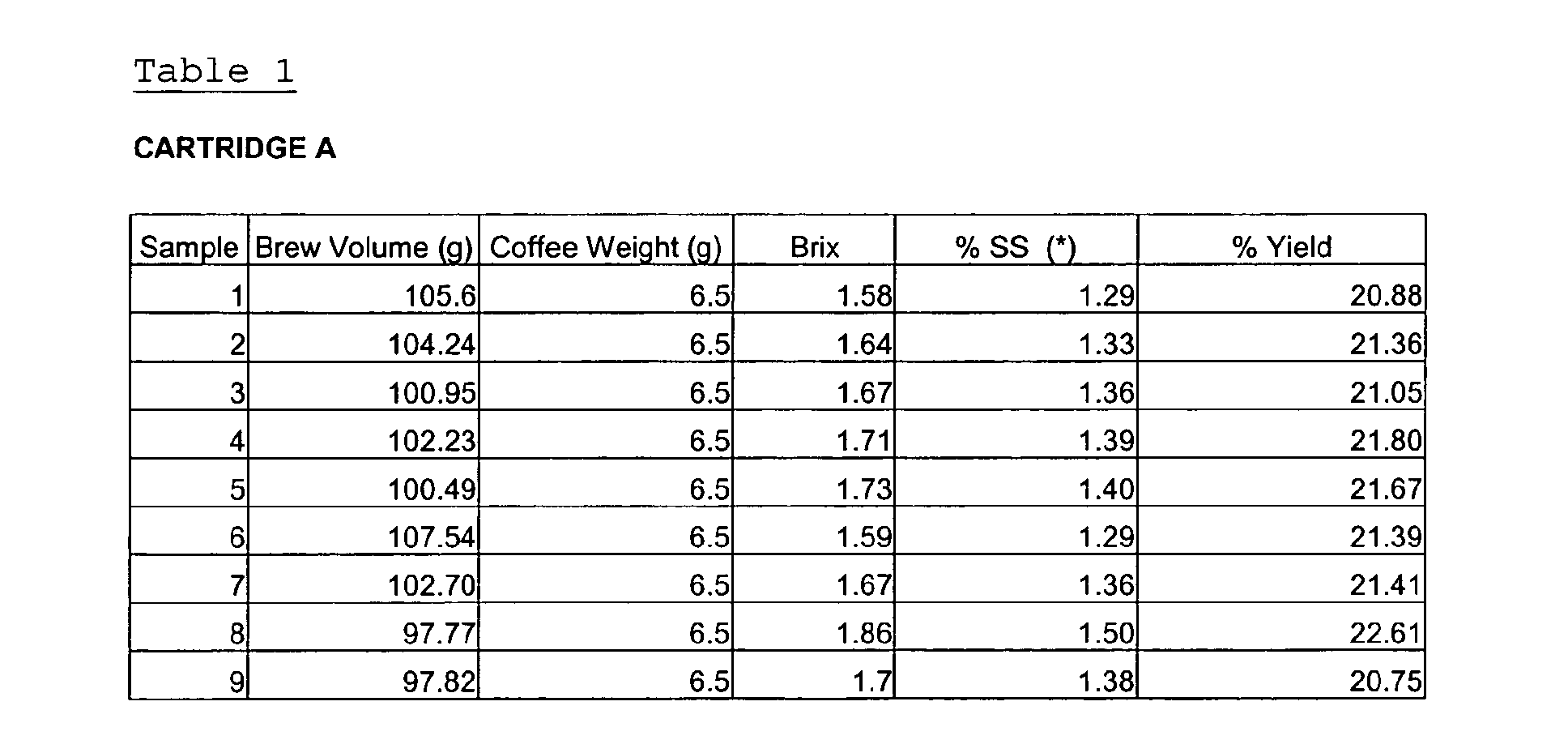

- Performing a t-test statistical analysis on the above data gives the following results:
t-Test: Two-Sample Assuming Equal Variances % Yield (Cartridge A) % Yield (Cartridge B) Mean 20.99 23.09 Variance 0.77 5.04 Observations 20 20 Pooled Variance 2.90 Hypothesized Mean Difference 0 df 38 t Stat -3.90 P(T<=t) one-tail 0.000188 t Critical one-tail 1.686 P(T<=t) two-tail 0.000376 t Critical two-tail 2.0244 Standard Deviation 0.876 2.245 - The analysis shows that the consistency of % yield, which equates to brew strength, for the cartridges of the present invention is significantly better (at a 95% confidence level) than the prior art cartridges, with a standard deviation of 0.88% compared to 2.24%. This means that beverages brewed with the cartridges of the present invention have a more repeatable and uniform strength. This is preferred by consumers who like their drinks to taste the same time after time and do not want arbitrary changes in brew strength.
- The materials of the cartridges described above may be provided with a barrier coating to improve their resistance to oxygen and/or moisture and/or other contaminant ingress. The barrier coating may also improve the resistance to leakage of the beverage ingredients from within the cartridges and/or reduce the degree of leaching of extractibles from the cartridge materials which might adversely affect the beverage ingredients. The barrier coating may be of a material selected from the group of PET, Polyamide, EVOH, PVDC or a metallised material. The barrier coating may be applied by a number of mechanisms including but not limited to vapour deposition, vacuum deposition, plasma coating, co-extrusion, in-mould labelling and two/multi-stage moulding.
- A
beverage preparation machine 201 according to the present invention for use with the above described beverage cartridges is shown in Figures 35 to 45. Thebeverage preparation machine 201 generally comprises ahousing 210 containing awater tank 220, awater heater 225, awater pump 230, anair compressor 235, a control processor, auser interface 240 and acartridge head 250. Thecartridge head 250 in turn generally comprises acartridge holder 251 for holding, in use, the beverage cartridge 1, cartridge recognition means 252 and inlet andoutlet piercers inlet 121 and theoutlet 122 in the beverage cartridge 1. - The
housing 210 contains and holds in position the other components of themachine 201. Thehousing 210 preferably made in whole or in part from a robust plastics material such as ABS. Alternatively, thehousing 210 can be made in whole or in part from a metallic material such as stainless steel or aluminium. Thehousing 210 is preferably comprises a clam-shell design having afront half 211 and arear half 212 which allow access during assembly for fitting of themachine 201 components and can afterwards be joined together to define an interior 213 of thehousing 210. Therear half 212 provides arecess 214 for the attachment of thewater tank 220. Thehousing 210 is formed with means, such as detents, abutments, bosses and threaded portions, for retaining the components of themachine 201 in position without the need for a separate chassis. This reduces the overall cost and weight of themachine 201. Abase 215 of thehousing 210 is preferably provided with feet for standing the machine thereon in a stable manner. Alternatively, the base 215 itself may have a shape forming a stable support. - The
front half 211 of thehousing 210 comprises a dispensestation 270 where dispensation of the beverage takes place. The dispensestation 270 comprises areceptacle stand 271 having a hollow interior forming adrip tray 272. Anupper surface 273 of the receptacle stand is provided with agrill 274 on which the receptacle is positioned. Thedrip tray 272 is removable from thehousing 210 to ease emptying of the collected water. Arecess 275 is formed in the front half of thehousing 210 above the receptacle stand 271 to accommodate the dimensions of the receptacle. - The
cartridge head 250 is located towards the top of thehousing 210 above the receptacle stand as shown in Figures 35 and 36. Preferably, the height of thegrill 274 relative to thecartridge head 250 can be adjusted to accommodate different sizes of receptacle. It is preferred that the receptacle is as close to thecartridge head 250 as possible, whilst still allowing the receptacle to be inserted and withdrawn from the dispensestation 270, so as to minimise the height that the dispensed beverage has to descend before contacting the receptacle. This acts to minimise spraying and splashing of the beverage and minimise loss of entrained air bubbles where these are present. Preferably receptacles of between 70mm and 110 mm in height can be inserted between thegrill 274 andcartridge head 250. - The
machine user interface 240 is located on the front of thehousing 210 and comprises a start/stop button 241, and a plurality of status indicators 243-246. - The status indicators 243-246 preferably include a light emitting diode (LED) 243 to indicate readiness of the
machine 201, aLED 244 to indicate if an error has occurred in themachine 201 operation, and one or more LEDs 245-256 to indicate whether themachine 201 is operating in manual or automatic modes. The LEDs 243-246 may be controlled to illuminate at a constant intensity, to flash intermittently, or both depending on the status of themachine 201. The LEDs 243-246 may have a variety of colours including green, red and yellow. - The start/
stop button 241 controls commencement of the operating cycle and is a manually operated push-button, switch or similar. - A volume adjustment control may be provided to allow a user of the
machine 201 to manually adjust the volume of the delivered beverage without altering the other operating characteristics. Preferably the volume adjustment control allows an adjustment in volume of plus or minus 20%. The volume adjustment control may be a rotary knob, a linear slider, a digital readout with increment and decrement buttons, or similar. More typically, volume is controlled by a user operating the start/stop button 241. - A manual power switch (not shown) may be provided on the
machine 201. Alternatively, power supply can be controlled simply by insertion or removal or the power supply plug from the mains power supply. - The
water tank 220 is located to the rear of thehousing 210 and is connected to therear half 212 of thehousing 210. Thewater tank 220 comprises a generallycylindrical body 221 which may be right circular or a frustum as desired for aesthetic reasons. The tank comprises an inlet for filling the tank with water which is closed off in use by a manuallyremovable lid 222. An outlet is provided towards a lower end of the tank which communicates with thewater pump 230. Thewater tank 220 may be made from a transparent or translucent material to allow a consumer to view the quantity of water remaining in the tank. Alternatively, thewater tank 220 may be made from an opaque material but have provided a viewing window therein. In addition, or in place of the above, thewater tank 220 may be provided with a low level sensor which prevents operation of thewater pump 230 and optionally triggers a warning indicator, such as an LED, when the water level in the tank descends to a preselected level. Thewater tank 220 preferably has an internal capacity of approximately 1.5 litres. - The
water pump 230 is operatively connected between thewater tank 220 and thewater heater 225 as shown schematically in Figure 43 and is controlled by the control processor. The pump provides a maximum flow rate of 900 ml/min of water at a maximum pressure of 2.5 bar. Preferably, in normal use, the pressure will be limited to 2 bar. The flow rate of water through themachine 201 can be controlled by the control processor to be a percentage of the maximum flow rate of the pump by cycle chopping the electrical supply to the pump. Preferably the pump can be driven at any of 10%, 20%, 30%, 40%, 50%, 60%, 70%, 80%, 90% or 100% of the maximum rated flow rate. The accuracy of the volume of water pumped is preferably + or - 5% leading to a + or - 5% accuracy in the final volume of the dispensed beverage. A suitable pump is the Evolution EP8 pump produced by Ulka S.r.l. (Pavia, Italy). A volumetric flow sensor (not shown) is preferably provided in the flow line either upstream or downstream of thewater pump 230. Preferably, the volumetric flow sensor is a rotary sensor. - The
water heater 225 is located in the interior of thehousing 210. Theheater 225 has a power rating of 1550 W and is able to heat water received from thewater pump 230 from a starting temperature of approximately 20 °C to an operating temperature of around 85 °C in under 1 minute. Preferably the dwell time between the end of one operating cycle and theheater 225 being able to commence a subsequent operating cycle is less than 10 seconds. The heater maintains the selected temperature to within + or - 2 °C during the operating cycle. As discussed below, the water for the operating cycle may be delivered to thecartridge head 250 at 83 °C or 93 °C. Theheater 225 is able to quickly adjust the delivery temperature to either 83 °C or 93 °C from a nominal water temperature of 85 °C. Theheater 225 comprises an over-temperature cut-off which shuts off the heater if the temperature exceeds 98 °C. Water output from theheater 225 is fed to thecartridge head 250 and cartridge 1 by means of a three-way valve. If the pressure of the water flow is acceptable the water is passed to the cartridge 1. If the pressure is below or above predetermined limits then the water is diverted by means of the three-way valve into the driptray recovery receptacle 270. - The
air compressor 235 is operatively connected to thecartridge head 250 by means of a one-way valve and controlled by the control processor. Theair compressor 235 provides a maximum flow rate of air of 500 ml/min at 1.0 bar. In use a working volume of 35 ml is pressurised to 2.0 bar. Preferably, theair compressor 235 can produce two flow rates: a fast (or maximum) flow rate and a slow flow rate. - The control processor of the
beverage preparation machine 201 comprises a processing module and a memory. The control processor is operatively connected to, and controls operation of, thewater heater 225,water pump 230,air compressor 235 anduser interface 240. - The memory of the control processor includes one or more variables for one or more operational parameters for the
beverage preparation machine 201. In the illustrated embodiment the operational parameters are the temperature of the water passed through the beverage cartridge 1 during the operating stage, the speed of charging the beverage cartridge 1, the presence or otherwise of a soak step, the total dispensed volume of the beverage, the flow rate of the water during the discharge stage, and the flow rate and period of the purge stage. - The variables for the operational parameters are stored in the memory. The cartridge 1 comprises a code provided on or in the cartridge 1 representing the operational parameters required for optimal dispensation of the beverage in that cartridge 1. The code is in binary format and comprises a plurality of data bits corresponding to the variables stored in the control processor memory. Table 3 illustrates how 13 bits of data can be used to represent the necessary variables for the operational parameters described above.
Bit Parameter Description 0 & 1 Water temperature 00 = cold 01 = warm 10 = 83 ° C 11 = 93 ° C 2 & 3 Cartridge charge 00 = fast charge with soak 01 = fast charge without soak 10 = slow charge with soak 11 = slow charge without soak 4, 5, 6 & 7 Beverage volume 0000 = 50 ml 0001 = 60 ml 0010 = 70 ml 0011 = 80 ml 0100 = 90 ml 0101 = 100 ml 0110 = 110 ml 0111 = 130 ml 1000 = 150 ml 1001 = 170 ml 1010 = 190 ml 1011 = 210 ml 1100 = 230 ml 1101 = 250 ml 1110 = 275 ml 1111 = 300 ml 8, 9 & 10 Flow rate 000 = 30% 001 = 40% 010 = 50% 011 = 60% 100 = 70% 101 = 80% 110 = 90% 111 = 100% 11 &12 Purge 00 = slow flow/short period 01 = slow flow/ long period 10 = fast flow/ short period 11 = fast flow/long period - The code on or in the cartridge 1 will normally comprises one or more extra data bits for error checking. In one example a 16 bit code is provided. For example, using the variables listed in Table 3, a cartridge 1 bearing the code "1000100011110" would have the following operational parameters:
10 Water temperature of 83 °C 00 Fast charge with soak 1000 Dispensed drink volume of 150ml 111 Flow rate equals 100% 10 Fast air flow purge/short period. - Thus, unlike in previous beverage preparation machines, the memory of the control processor does not store operational instructions for beverage cartridges based on the cartridge type, i.e. instructions for a coffee cartridge, instructions for a chocolate cartridge, instructions for a tea cartridge etc. Instead the memory of the control processor stores variables for adjusting the individual operational parameters of the operating cycle. This has a number of advantages. Firstly, a greater degree of control of the dispensation cycle can be exercised. For example, slightly different operational parameters can be used for different grades or blends of coffee rather than using the same parameters for all types of coffee. Prior coding solutions relying on storing instructions by cartridge type rather than by individual parameters are unsuited to such subtle differences in operating cycles for similar beverage types because they quickly consume the available storage space in the coding medium and control processor. Secondly, the coding method of the present invention allows for new beverage cartridge types to be used in pre-existing beverage preparation machines even where the operational parameters for the operating cycle for the new beverage cartridge 1 are only decided upon after sale of the
beverage preparation machine 201. This is because the control processor of thebeverage preparation machine 201 does not need to recognise that the beverage is of a new type. Rather the operational parameters of the operating cycle are set without direct reference to the beverage type. Hence the coding method of the present invention provides excellent backward compatibility of the beverage preparation machines for new beverage types. In contrast, with prior machines, the manufacturer is restricted to dispensing a new beverage type using one of the pre-existing dispensation cycles as determined by the in-market machines. - The
cartridge head 250 is shown in Figures 39 to 42. Thecartridge holder 251 of thecartridge head 250 comprises a fixedlower part 255, a rotatableupper part 256 and apivotable cartridge mount 257 positioned inbetween the fixedlower part 255 and the rotatableupper part 256. Theupper part 256,lower part 255 andcartridge mount 257 are rotated about acommon hinge axis 258. Figures 39 to 42 show thecartridge holder 251 with some components of themachine 201 omitted for clarity. - The rotatable
upper part 256 andpivotable cartridge mount 257 are moved relative to the fixedlower part 255 by means of aclamping mechanism 280. Theclamping mechanism 280 comprises a clamping lever having first and second members orparts first part 281 of the clamping lever comprises a U-shaped arm which is pivotably mounted to theupper part 256 at two first pivot points 283, one on each side of thecartridge holder 251. - The second part of the clamping lever comprises two
over-centre arms 282, one on each side of thecartridge holder 251 which are each pivotably mounted to theupper part 256 at a second pivot point 285 located on thehinge axis 258 coupling theupper part 256 to the fixedlower part 255. Eachover-centre arm 282 is a reciprocal member comprising a cylinder 282a, a stem 282b and a resilient sleeve 282c. The cylinder 282a has an internal bore and is rotatably mounted at one end at thehinge axis 258. A first end of the stem 282b is slidingly received in the bore of the cylinder 282a. The opposite end of the stem 282b is rotatably mounted to theU-shaped arm 281 at athird pivot point 286. The third pivot points 286 are unconnected to, and freely moveable relative to, theupper part 256 andlower part 255. The resilient sleeve 282c is mounted externally on the stem 282b and extends, in use, between abutment surfaces on the cylinder 282a and stem 282b. The resilient sleeve 282c accommodates shortening of theover-centre arm 282 but biases theover-centre arm 282 into an extended configuration. Movement of the third pivot points 286 towards and away from thehinge axis 258 is thus possible by relative movement of the stems 282b in the cylinders 282a. The resilient sleeves 282c are preferably formed from silicone. - The
U-shaped arm 281 extends around the front of thecartridge holder 251 and comprises two downwardlydependant hook members 287, one on each side of thecartridge holder 251, each comprising acam surface 288 facing thehinge axis 258. The fixedlower part 255 of thecartridge holder 251 is provided with twobosses 259, or detents, located one on each side of thelower part 255 at or near afront edge 260 thereof aligned generally with thehook members 287. - As shown in Figure 39, the
U-shaped arm 281 may be formed from a one piece plastics moulding comprising an ergonomic hand grip and thehook members 287 integral to the arm. - The
cartridge mount 257 is rotatably mounted between the upper andlower parts cartridge holder 251. Themount 257 is provided with a substantiallycircular recess 290 which receives in use the beverage cartridge 1. Therecess 290 includes anirregularity 291 for accommodating thehandle portion 24 of the beverage cartridge 1 which also acts to prevent rotation of the beverage cartridge 1 in thecartridge holder 251. Thecartridge mount 257 is sprung relative to the fixedlower part 255 such that in the open position, as shown in Figure 41, thecartridge mount 257 is biased out of contact with the fixedlower part 255 so that thecartridge mount 257 is moved out of contact with the outlet andinlet piercer members cartridge mount 257 is provided with anaperture 292 for receiving therethrough the inlet andoutlet piercers head 300 of the cartridge recognition means 252 when thecartridge mount 257 is moved into the closed position. - The
upper part 255 comprises a generallycircular body 310 housing acircular viewing window 312 through which a consumer can view the beverage cartridge 1 during an operating cycle and also visually confirm whether a cartridge 1 is loaded in themachine 201. Theviewing window 312 is cup-shaped having a downwardly directedrim 311 which engages and grips theflange 35 of the beverage cartridge 1 against thelower part 256 when thecartridge holder 251 is closed. At the same time thewindow 312 contacts theclosed top 11 of the cartridge 1. A wave spring (not shown) is positioned between theviewing window 312 and thecircular body 310 to enable theviewing window 312 to move axially relative to thecircular body 310 by a small degree. The pressure exerted by therim 311 on theflange 35 and by thewindow 312 on the closed top 11 ensures a fluid tight seal between the cartridge 1 and thecartridge holder 251. - The
lower part 255 comprises the inlet andoutlet piercers head 300 of the cartridge recognition means 252. Theinlet piercer 253 comprises a hollow needle-like tube 260 having a sharpenedend 261 for perforating thelaminate 5 of the beverage cartridge 1 in use. Theinlet piercer 253 is in fluid communication with awater conduit 262 as shown in Figure 42 which passes through thelower part 255 and is connected to anoutlet conduit 263 of thewater heater 225. Theoutlet piercer 254 is similar in type to the outlet piercer described in the applicant's European patents EP 0 389 141 and EP 0 334 572 and comprises an open ended cylinder 264 of circular or D-shaped cross-section having dimensions larger than thedischarge spout 43. Anarcuate portion 265 of the upper end of theoutlet piercer 254 is serrated to pierce and eventually cut the laminate of the beverage cartridge 1. The remainder of the upper end is cut back longitudinally of the cylinder at least to the base of theteeth 266 of the serrated portion to fold or pull thecut laminate 5 away from the outlet aperture before the beverage is dispensed therethrough. Theoutlet piercer 254 pierces thelaminate 5 externally of thedischarge spout 43 and when thecartridge mount 257 is in the closed position, rests in the annulus between thedischarge spout 43 and theouter wall 42 of thedischarge funnel 40. Theoutlet piercer 254 folds back the cut laminate 105 into the annulus. Thereby both theoutlet piercer 254 and the cut laminate 105 are held out of the way of the discharged beverage. - The
outlet piercer 254 is surrounded by aledge 254a which is raised relative to its surroundings by 0.5mm. - Advantageously, the
outlet piercer 254 is removable from thelower part 255 to enable it to be thoroughly cleaned, for example, in a dishwasher. Theremovable outlet piercer 254 is received in a recess 267 in thelower part 255 where it is seated. Theinlet piercer 253 and/or theoutlet piercer 254 may be made of a metal, such as stainless steel, or from a plastics material. Advantageously, the use of plastic cutting elements is enabled by use of alaminate 5 which is able to be punctured and cut by a non-metallic material. Consequently, thepiercers inlet piercer 253 and theoutlet piercer 24 are formed as a single, integral unit which is removable from thelower part 255. - In use, the
upper part 256 of thecartridge holder 251 is movable from an open position in which it is orientated vertically or towards the vertical as shown in Figure 36, to a closed position in which it is orientated substantially horizontally and in interengagement with the fixedlower part 255 andcartridge mount 257. Theupper part 256 is moved from the open to the closed positions by operation of the clamping lever. To close the upper part 256 a user takes hold of the clamping lever by theU-shaped arm 281 and pulls downwards. Consequently, theupper part 256 rotates which first brings therim 311 of theviewing window 312 into contact with theflange 35 of the beverage cartridge 1 in thecartridge mount 257 and thewindow 312 itself into contact with theclosed top 11 of the cartridge 1. Continued rotation of theupper part 256 rotates theupper part 256 andcartridge mount 257 down into contact with thelower part 255. Further rotation of theU-shaped arm 281 causes theU-shaped arm 281 to rotate relative to theupper part 256 and thelower part 255 resulting in thehook members 287 of theupper part 256 engaging thebosses 259 of thelower part 255 with thecam surface 288 riding over thebosses 259. During this last stage of rotation the cartridge 1 is compressed between thecartridge mount 257 and theviewing window 312. As a result, theviewing window 312 is moved axially relative to thecircular body 310 of theupper part 256 against the bias of the wave spring. This movement allows for a take up of tolerances in the beverage cartridge 1 and beverage preparation machine and ensures that the amount of compressive force applied to the cartridge is kept within an acceptable range. The clamping force of the mechanism as moderated by the action of the wave spring ensures a clamping pressure on the cartridge of between 130 and 280N. Preferably the force is approximately 200N. A force less than about 130N does not provide an adequate seal, whilst a force greater than about 280N leads to plastic failure of the components of the cartridge 1. During closure of the cartridge head thelaminate 5 of the cartridge 1 is tensioned as it is brought into contact with theledge 254a surrounding theoutlet piercer 254 which causes thelaminate 5 to flex out of plane as the distal end of theouter tube 42 of the cylindrical funnel is moved upwardly by 0.5mm relative to theflange 35. This movement also ensures that the great majority of the compressive force applied to the cartridge acts through the central region of the cartridge 1 through the load-bearinginner member 3. In the closed position the cartridge 1 is thus clamped around theflange 35 by means of therim 311 of theviewing window 312 and firmly clamped between theclosed top 11 of the cartridge and theouter tube 42 of theinner member 3 by contact with theviewing window 312 and theledge 254a. These clamping forces help prevent failure of the cartridge 1 during pressurisation and also ensure that theinner member 3 andouter member 2 are fully seated relative to one another and thus that all internal passageways and apertures remain at their intended dimensions even during internal pressurisation. - An imaginary datum line can be drawn between the first and second pivot points 283, 285 of the
cartridge holder 251. As can be seen in Figure 41, in the open position the third pivot points 286 are located on the side of the datum line nearest the fixedlower part 255. As theupper part 256 reaches the closed position, the third pivot points 286 of the clamping lever pass through the datum line joining the first and second pivot points 283, 285 to the opposite side of the line, furthest from the fixedlower part 255. Consequently, the U-shaped arm 281 'snaps through' from a first stable position to a second stable position. The snap through action is accommodated by shortening of theover-centre arms 282 and consequential compression of the resilient sleeves 282c. Once the third pivot points 286 are past the imaginary datum line then recovery of the resilient sleeves 282c acts to continue the motion of the third pivot points 286 away from the imaginary datum line. The clamping lever thus has a bi-stable operation in that the lever is stable in the open or closed positions but unstable at the point when the third pivot points 286 lie on the imaginary datum line joining the first and second pivot points 283, 285. Thus, the snap-through action of the clamping lever provides a positive closure mechanism which leads to a definite closure action wherein in the final stages of the clamping lever's rotation, the snap-through action of theU-shaped arm 281 and second arms 284 forces thehook members 287 firmly into engagement with thebosses 259. In addition, the resilient sleeves 282c provide a resistance to re-opening of theupper part 256 since a minimum force is required to compress the sleeves 282c sufficiently to move the third pivot points 286 back into line with the datum line joining the first and second pivot points 283, 285. Advantageously, the interengagement of thehook members 287 and thebosses 259 prevents separation of the upper and lower parts other than by rotation of the clamping lever. This is useful in preventing opening of thecartridge head 250 during operation when thecartridge head 250 is subject to internal pressurisation. - The purpose of the cartridge recognition means 252 is to allow the
machine 201 to recognise the type of beverage cartridge 1 that has been inserted and to adjust one or more operational parameters accordingly. In a typical embodiment, the cartridge recognition means 252 comprises an optical barcode reader which reads a printedbarcode 320 provided on thelaminate 5 of the beverage cartridge 1 as shown in Figure 45. Thebarcode 320 is formed from a plurality of bars of contrasting colour. Preferably the bars are black on a white background to maximise the contrast. Thebarcode 320 is not required to conform to a published standard but a standard format for barcodes, such as EAN-13, UPC-A, orInterleaved 2 of 5 may be used. The optical barcode reader comprises one ormore LEDs 321 to illuminate thebarcode 320, a focusinglens 322 to acquire an image of the barcode, a charge coupled device (CCD) 323 for producing an electrical signal representative of the acquired image and support circuitry for the LEDs and CCD. The space in the lower part for accommodating the barcode reader is limited. A mirror or mirrors 324 may be used to reflect the light from theLEDs 321 to a focussing lens which is not located in thelower part 255. Schematic arrangements are shown in Figures 44a and 44b. Thelower part 255 comprises an aperture 326 which is the same size as thebarcode 320 on the beverage cartridge 1. In use the electrical signals produced are decoded by signal processing software and the results forwarded to the control processor. The software can recognise whether the read of the barcode contained errors. Thebarcode 320 may be rescanned a number of times before an error message is presented to the consumer. If themachine 201 is unable to read the barcode the consumer is able to use the beverage cartridge 1 to dispense a beverage using a manual mode of operation. - The
cartridge head 250 also includes a cartridge sensor for detecting whether a cartridge is present in thecartridge holder 251. - The
cartridge head 250 also includes a lock sensor which detects whether thecartridge holder 251 is properly closed. Preferably the lock sensor comprises a micro-switch which is triggered when thecartridge holder 251 is closed and locked. Preferably the cartridge sensor and lock sensor are connected in series such that the output of both sensors must be satisfactory, i.e. cartridge present and mechanism locked, before the operating cycle can be commenced. - Operation of the
machine 201 comprises insertion of a beverage cartridge 1 into thecartridge head 250, carrying out an operating cycle in which the beverage is dispensed and removal of the cartridge 1 from the machine. - The operational behaviour of the
machine 201 is determined by software embedded in the control processor. Operation of the machine can be described in terms of 'States', wherein themachine 201 will normally exist in a particular State until an event occurs to change the State, a step called a State transition. - Table 4 shows a State Transition Table which illustrates the States and State transitions for one embodiment of the
beverage preparation machine 201.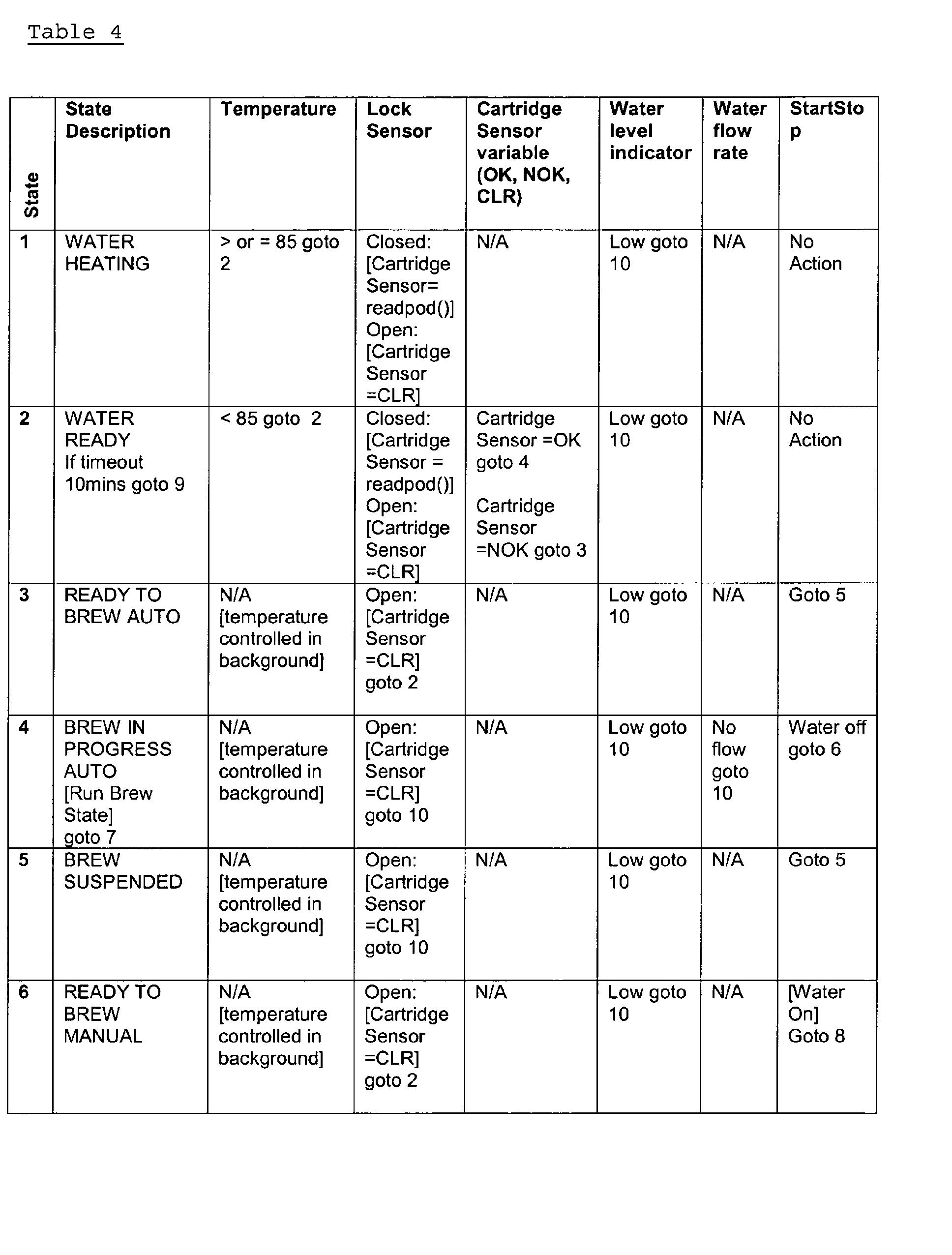

- The following example illustrates an operating cycle to exemplify the use of the State Transitions by the control processor.
- It is assumed that the
machine 201 is initially switched off and with no cartridge 1 inserted in thecartridge head 250. When themachine 201 is switched on the control processor is in State 1. Thewater heater 225 is switched on. Once the temperature reaches 85 °C the control processor transits toState 2. If at any time duringState 1 or 2 thecartridge holder 251 is closed the lock sensor will be triggered to send a signal to the control processor indicating that thecartridge holder 251 is properly closed. The control processor then interrogates the cartridge sensor by sending a 'readpod' instruction. The cartridge sensor returns a signal to the control processor indicating whether a cartridge is in place in thecartridge holder 251. If no cartridge is present the control processor transits toState 3 where it remains in a readiness state until thecartridge holder 251 is reopened at which point the control processor transits back toState 2. If a cartridge is present inState 2 then the control processor transits to State 4 and operation is commenced automatically. During States 4 to 9 the water temperature is controlled in the background to remain within the required tolerance range of the desired temperature as set by the operational parameters set by the barcode on the beverage cartridge 1. Once the discharge stage of dispense is completed an air purge is commenced in State 8. Once the air purge is completed the operating cycle is completed and the machine enters to standby mode inState 10. If, during operation, an error occurs then the processor transits toState 11. If a low water level is detected then the processor transits toState 12. - To insert the cartridge 1 the
cartridge holder 251 is opened as described above to expose thecartridge mount 257. The cartridge 1 is then placed on thecartridge mount 257 received within therecess 290 such that thehandle 24 of the cartridge is located in theirregularity 291. The optical ormagnetic barcode 320 of the cartridge 1 is orientated directly above the aperture 326 in thecartridge mount 257. Thecartridge holder 251 is then closed by operation of the clamping lever as described above. During closure the inlet andoutlet piercers laminate 5 of the cartridge 1 to form thecartridge inlet 121 andoutlet 122. As described above thelaminate 5 cut by theoutlet piercer 254 is folded up into the annulus surrounding thedischarge spout 43. When closed thecartridge holder 251 grips the cartridge 1 around therim 35 between thecartridge mount 257 and theupper part 256 and between thewindow 311 and the top 11 of the cartridge 1 to form a fluid tight seal of sufficient integrity to withstand the pressures developed during the operating cycle. - To commence the operating cycle the consumer operates the start/
stop button 241. - The operating cycle comprises the steps of cartridge recognition and the discharge cycle.
- Cartridge recognition is performed by the optical cartridge recognition means 252 as described above assuming that the outputs from the cartridge sensor and lock sensor are satisfactory. Once the
barcode 320 has been decoded the operational parameters of themachine 201 are adjusted by the control processor. The discharge cycle is then automatically commenced. - The discharge cycle has four main stages, not all of which are used for all beverage types:
- (i) Pre-wet
- (ii) Pause
- (iii) Brew/Mixing
- (iv) Purge
-
- In the pre-wet stage the cartridge 1 is charged with water from the
water storage tank 220 by means of thewater pump 230. The charging with water causes thebeverage ingredients 200 in thefiltration chamber 130 to be wetted. The charging may take place at a "fast" flow rate of 600 ml/min or a "slow" flow rate of 325 ml/min. The slow charging rate is particularly useful for cartridges containing viscous liquid beverage ingredients where the ingredients require some dilution before they are able to be pumped at a higher volume flow rate. The volume of water injected into the cartridge 1 is selected to ensure that water or beverage does not drip out of thecartridge outlet 122 during this stage. - The pause stage allows the
beverage ingredients 200 to soak in the water injected during the pre-wet stage for a predetermined period of time. Both the pre-wetting and soaking stages are known to increase the yield of the extractibles from thebeverage ingredients 200 and to improve the end flavour of the beverage. Pre-wetting and soaking are particularly used where the beverage ingredients are roast and ground coffee. - In the brew/mixing stage water is passed through the cartridge 1 in order to produce the beverage from the
beverage ingredients 200. The temperature of the water is determined by the control processor which sends instructions to thewater heater 225 to heat the water passing from thewater tank 220 to thecartridge head 250. Water enters thelower part 255 of thecartridge holder 251 through theconduit 262 via the inlet valve and theinlet piercer 253 into theinlet chamber 126 of the beverage cartridge 1. Brewing and/or mixing and subsequent dispensing of the beverage from the beverage cartridge 1 is as described above with reference to the versions of the beverage cartridge 1. - The air purge comprises the blowing of pressurised air through the beverage preparation machine and the beverage cartridge 1 to ensure that all beverage is dispensed and that the flow path is cleared ready for dispensing another beverage. The air purge does not commence immediately on cessation of the brew/mixing stage to allow for the majority of the fluid to clear the flow path. This prevents an unacceptable spike in internal pressure on commencement of the air purge.
- In normal operation a user manually stops the
machine 201 by operating the start/stop button 241. - Once the operating cycle has been completed the consumer removes the cartridge 1 by opening the
cartridge holder 251 and manually removing and disposing of the cartridge. Alternatively, themachine 201 may be provided with an automatic ejection mechanism for removing the cartridge automatically on opening thecartridge holder 251. - The delivery times for beverages using the
machine 201 and cartridges 1 are typically between 10 and 120 seconds, preferably 30 to 40 seconds for roast and ground coffee, between 5 and 120 seconds, preferably 10 to 20 seconds for chocolate and between 5 and 120 seconds, preferably 10 to 20 seconds for milk. - The
machine 201 may also advantageously comprise a memory in operative communication with the control processor that stores information on the type of beverage dispensed by a user. The operating cycle of themachine 201 may then be adjusted for the next cartridge 1. This is especially advantageous where two or more beverage cartridges 1 are used sequentially to form a beverage. For example a coffee cartridge may be dispensed followed by a milk cartridge to form a cappuccino beverage. Alternatively a chocolate cartridge could be used followed by a milk cartridge to produce a creamy hot chocolate beverage. By using a memory that stores information on the first beverage dispensed, the manner of dispensing the second cartridge, say a milk cartridge, may be altered to achieve an optimum beverage. In the above example the milk dispensed for hot chocolate may, typically, be diluted less than the milk added to the coffee. In addition, the milk dispensed for chocolate may be dispensed at a slower flow rate to lessen the degree of foaming of the beverage. Many combinations of cartridges are possible and operating parameters as will be obvious to the skilled person. In addition, the memory may be used to allow themachine 201 to 'predict' the type of beverage that a user will next want to dispense. For example, if a user predominantly drinks one beverage type then the machine can instruct the water heater to remain at the optimum temperature for that beverage type.
Claims (17)
- A low pressure beverage preparation system for automatically preparing a range of beverage types from a range of beverage cartridges, the system comprising:wherein the beverage preparation system can produce a range of beverage types including at least, but not limited to, filtered coffee, cappuccino, tea, chocolate and frothed milk, anda beverage preparation machine (201);and a plurality of beverage cartridges (1), each beverage cartridge containing one or more beverage ingredients (200) associated with a specific beverage type, wherein the beverage preparation system comprises:a. means for receiving one of said plurality of beverage cartridges in said beverage preparation machine and means for supplying, in use, to said beverage cartridge an aqueous medium at a pressure of less than 2 bar to produce a beverage from the one or more beverage ingredients contained therein;b. a reader (252) in said beverage preparation machine for automatically interpreting a code (320) written on said beverage cartridge;c. processing means for creating a specific brewing cycle based on said code;d. means for automatically adjusting a temperature of said aqueous medium based on said code prior to supply of said aqueous medium to the beverage cartridge;e. means in at least some of said plurality of beverage cartridges for optionally, dependant on beverage type, producing foaming of the beverage; andf. a user interface (240) for initiating an operating cycle;
wherein operation of the user interface is independent of the beverage type being dispensed. - A low pressure beverage preparation system as claimed in claim 1 wherein the range of beverage types includes coffee, tea, chocolate, milk, soup and fruit juices.
- A low pressure beverage preparation system as claimed in any preceding claim wherein the beverage preparation machine (201) further comprises means for purging the beverage cartridge after dispensing of the beverage.
- A low pressure beverage preparation system as claimed in any preceding claim further comprising means for controlling the flow rate of aqueous medium into the cartridge.
- A low pressure beverage preparation system as claimed in any preceding claim further comprising means for controlling the volume of aqueous medium delivered to the cartridge.
- A low pressure beverage preparation system as claimed in any preceding claim wherein one or more of the beverage ingredients is a liquid.
- A low pressure beverage preparation system as claimed in any preceding claim wherein one or more of the beverage ingredients is dairy-based.
- A low pressure beverage preparation system as claimed in any preceding claim wherein the system may also be used with one or more cartridges comprising one or more non-beverage ingredients, for preparation of non-beverage products, such as sauces and desserts.
- A low pressure beverage preparation system comprising a beverage preparation machine (201) and a plurality of beverage cartridges (1), each beverage cartridge containing one or more beverage ingredients (200), wherein the beverage preparation machine comprises processing means and a memory for storing information about the beverage cartridges dispensed by the beverage preparation machine.
- A low pressure beverage preparation system as claimed in claim 9 wherein the memory stores information about the beverage ingredients contained in the beverage cartridges dispensed by the beverage preparation machine.
- A low pressure beverage preparation system as claimed in claim 9 or claim 10 wherein the memory stores information about the order of beverage cartridges dispensed by the beverage preparation machine.
- A low pressure beverage preparation system as claimed in any preceding claim wherein the reader is an optical bar code reader.
- A low pressure beverage preparation system as claimed in any preceding claim being a domestic low pressure beverage preparation system.
- A method of preparing at least one of a range of beverages comprising the steps of:wherein the method can produce a range of beverage type using one or more beverage cartridges including at least, but not limited to, filtered coffee, cappuccino, tea, chocolate and frothed milk, and wherein operation of the user interface is independent of the beverage type being dispensed.a. inserting at least one beverage cartridge (1) containing one or more beverage ingredients into a low pressure beverage preparation machine (201);b. operating a user interface of said beverage preparation machine to initiate an operating cycle;c. operating a reader to detect a code (320) written on said beverage cartridge;d. creating a specific brewing cycle based on said code;e. passing an aqueous medium through the beverage cartridge to produce a beverage, wherein the temperature, pre-wet, volume, flow rate and air purge of the aqueous medium is set based on the code;f. for at least some of the range of beverages, producing foaming of the beverage;
- A method of preparing a beverage comprising the steps of:wherein one or more operating parameters of the beverage preparation machine during dispensing of the second beverage cartridge are set with reference to the information stored in the memory on the type of the first beverage cartridge.a. inserting a first beverage cartridge (1) containing one or more beverage ingredients (200) into a beverage preparation machine (201);b. operating said beverage preparation machine to pass an aqueous medium through the first beverage cartridge at a pressure of less than 2 bar to dispense a first portion of said beverage into a receptacle;c. storing in a memory of said beverage preparation machine information on the type of the first beverage cartridge;d. inserting a second beverage cartridge (1) containing one or more beverage ingredients (200) into the beverage preparation machine; ande. operating the beverage preparation machine to pass an aqueous medium through the second beverage cartridge at a pressure of less than 2 bar to dispense a second portion of said beverage into the receptacle;
- A method as claimed in claim 15 further comprising using additional beverage cartridges to dispense three or more portions of a beverage.
- A method as claimed in claim 15 or claim 16 wherein the one or more operating parameters include:I. the temperature of the aqueous medium passed through the beverage cartridge;II. the flow rate of the aqueous medium;III. the presence or absence of a pre-wet stage;IV. the presence or absence or an air-purge stage;V. the pressure of the aqueous medium; and/orVI. the total volume of aqueous medium dispensed.
Priority Applications (2)
| Application Number | Priority Date | Filing Date | Title |
|---|---|---|---|
| EP05026204A EP1629752B9 (en) | 2003-01-24 | 2004-01-23 | Machine for the preparation of beverages |
| DE602004009718.7T DE602004009718T3 (en) | 2003-01-24 | 2004-01-23 | Apparatus for making beverages |
Applications Claiming Priority (2)
| Application Number | Priority Date | Filing Date | Title |
|---|---|---|---|
| GB0301747 | 2003-01-24 | ||
| GB0301747A GB2397509B (en) | 2003-01-24 | 2003-01-24 | A system for the preparation of beverages |
Related Child Applications (2)
| Application Number | Title | Priority Date | Filing Date |
|---|---|---|---|
| EP05026204A Division-Into EP1629752B9 (en) | 2003-01-24 | 2004-01-23 | Machine for the preparation of beverages |
| EP05026204A Division EP1629752B9 (en) | 2003-01-24 | 2004-01-23 | Machine for the preparation of beverages |
Publications (5)
| Publication Number | Publication Date |
|---|---|
| EP1440640A2 true EP1440640A2 (en) | 2004-07-28 |
| EP1440640A3 EP1440640A3 (en) | 2004-08-04 |
| EP1440640B1 EP1440640B1 (en) | 2007-10-31 |
| EP1440640B2 EP1440640B2 (en) | 2014-06-18 |
| EP1440640B9 EP1440640B9 (en) | 2014-09-10 |
Family
ID=9951808
Family Applications (2)
| Application Number | Title | Priority Date | Filing Date |
|---|---|---|---|
| EP04250390.4A Expired - Lifetime EP1440640B9 (en) | 2003-01-24 | 2004-01-23 | Machine for the preparation of beverages |
| EP05026204A Expired - Lifetime EP1629752B9 (en) | 2003-01-24 | 2004-01-23 | Machine for the preparation of beverages |
Family Applications After (1)
| Application Number | Title | Priority Date | Filing Date |
|---|---|---|---|
| EP05026204A Expired - Lifetime EP1629752B9 (en) | 2003-01-24 | 2004-01-23 | Machine for the preparation of beverages |
Country Status (23)
| Country | Link |
|---|---|
| EP (2) | EP1440640B9 (en) |
| JP (1) | JP2006517429A (en) |
| KR (1) | KR101073804B1 (en) |
| CN (1) | CN100591253C (en) |
| AR (1) | AR042914A1 (en) |
| AT (2) | ATE439783T1 (en) |
| AU (1) | AU2004206100A1 (en) |
| BR (1) | BRPI0406892A (en) |
| CA (2) | CA2773078C (en) |
| DE (2) | DE602004022661D1 (en) |
| DK (1) | DK1440640T3 (en) |
| ES (2) | ES2295778T5 (en) |
| GB (2) | GB2397509B (en) |
| HK (2) | HK1065693B (en) |
| LT (1) | LT2005079A (en) |
| MX (1) | MXPA05007864A (en) |
| NO (1) | NO20053933L (en) |
| PE (1) | PE20041029A1 (en) |
| PL (1) | PL204367B1 (en) |
| RU (1) | RU2331348C2 (en) |
| SI (1) | SI1629752T1 (en) |
| TW (1) | TWI352585B (en) |
| WO (1) | WO2004064585A1 (en) |
Cited By (27)
| Publication number | Priority date | Publication date | Assignee | Title |
|---|---|---|---|---|
| FR2874210A1 (en) * | 2004-08-10 | 2006-02-17 | Cie Mediterraneenne Des Cafes | CONDITIONING FOR INFUSION OF A MATERIAL TO INFUSE |
| WO2006077259A1 (en) * | 2005-01-24 | 2006-07-27 | Nestec S.A. | Method of preparing a nutritional composition |
| WO2008104751A1 (en) * | 2007-02-27 | 2008-09-04 | Kraft Foods R & D, Inc. | Improvements in or relating to a machine for the preparation of beverages |
| EP1974638A1 (en) | 2007-03-29 | 2008-10-01 | Tchibo GmbH | System with a drinks dispensing machine and with portion capsules |
| WO2010003878A1 (en) * | 2008-07-08 | 2010-01-14 | Nestec S.A. | Portion-controlled nutrition system and method using capsules |
| ITTO20081006A1 (en) * | 2008-12-30 | 2010-06-30 | Lavazza Luigi Spa | MACHINE FOR THE PREPARATION OF DRINKS WITH THE USE OF PODS OR CAPSULES |
| WO2010076263A1 (en) | 2008-12-30 | 2010-07-08 | Nestec S.A. | Process of brewing tea leaves contained in a capsule |
| EP2236437A1 (en) * | 2009-03-31 | 2010-10-06 | Nestec S.A. | Capsule with filter for preparing a liquid nutritional or food composition and related beverage production system |
| EP2345352A1 (en) | 2010-01-19 | 2011-07-20 | Nestec S.A. | Method for providing information to a user from a capsule for the preparation of a beverage using a code |
| EP2345351A1 (en) | 2010-01-19 | 2011-07-20 | Nestec S.A. | Capsule for the preparation of a beverage comprising an identification code |
| WO2011144719A1 (en) * | 2010-05-21 | 2011-11-24 | Nestec S.A. | Ergonomic handle & user-interface |
| WO2012080597A1 (en) | 2010-12-17 | 2012-06-21 | Jacques Pitoux | Apparatus for dispensing a hot drink for a household machine for infusing a powdered material packaged in metered amounts |
| RU2584111C2 (en) * | 2011-07-29 | 2016-05-20 | Крафт Фудс Р & Д, Инк. | Beverage preparation method and system and beverage preparation cartridge |
| US9352287B2 (en) | 2009-11-12 | 2016-05-31 | Formulanow, Llc | Apparatus and method for preparing a liquid mixture |
| WO2016176779A1 (en) * | 2015-05-07 | 2016-11-10 | Smart Wave Technologies Corp. | Signal and detection system for pairing products |
| WO2016203471A1 (en) * | 2015-06-15 | 2016-12-22 | Instachef Ltd | Food capsule apparatus and method of using thereof |
| EP3132725A1 (en) * | 2015-08-18 | 2017-02-22 | Eugster/Frismag AG | Beverage preparation device and method of operation |
| US9598230B2 (en) | 2004-01-14 | 2017-03-21 | Caffitaly System S.P.A. | Cartridge containing one serving of coffee powder for preparing a coffee beverage |
| US9648980B2 (en) | 2009-09-24 | 2017-05-16 | Koninklijke Douwe Egberts B.V. | Beverage cartridge |
| EP3167775A1 (en) * | 2015-11-16 | 2017-05-17 | Qbo Coffee GmbH | Machine for making beverages, system with drink preparation machine, method of controlling the same |
| EP3175745A1 (en) * | 2015-12-01 | 2017-06-07 | Qbo Coffee GmbH | Brewing module, capsule sensor module and machine for making beverages |
| US9907432B2 (en) | 2007-05-18 | 2018-03-06 | Koninklijke Douwe Egberts B.V. | Beverage preparation machines |
| US9918585B2 (en) | 2010-05-20 | 2018-03-20 | Teatek Co., Ltd. | Filtering apparatus for filtering a beverage in a beverage producing apparatus |
| WO2018122218A1 (en) * | 2016-12-29 | 2018-07-05 | Koninklijke Philips N.V. | Coffee brewing |
| DE102014108930B4 (en) | 2014-06-25 | 2019-05-16 | Eugster/Frismag Ag | A beverage preparation device and method for expanding a beverage type variety obtainable from a beverage preparation device |
| US10368686B2 (en) | 2014-01-03 | 2019-08-06 | Koninklijke Douwe Egberts B.V. | Method for taking into use an exchangeable supply pack in a beverage dispensing machine and system comprising an exchangeable supply pack and computer program product |
| US10442611B2 (en) | 2003-01-24 | 2019-10-15 | Koninklijke Douwe Egberts B.V. | Machine for the preparation of beverages |
Families Citing this family (72)
| Publication number | Priority date | Publication date | Assignee | Title |
|---|---|---|---|---|
| US8505440B2 (en) | 2003-07-22 | 2013-08-13 | The Coca-Cola Company | System for varying coffee intensity |
| US8327754B2 (en) | 2003-07-22 | 2012-12-11 | The Coca-Cola Company | Coffee and tea pod |
| EP1609398A1 (en) * | 2004-06-25 | 2005-12-28 | Nestec S.A. | Verfahren zum Verbessern der Produktion von Schaum während der Herstellung von Getränken ausgehend von einer Kartusche und Vorrichtung zur Durchführung des Verfahrens |
| US7401545B2 (en) * | 2004-11-09 | 2008-07-22 | Nestec S.A. | Method and apparatus for optimizing variable liquid temperatures |
| EP1774878B1 (en) * | 2005-10-14 | 2008-01-23 | Nestec S.A. | Method for preparing a beverage from a capsule |
| DE202006007056U1 (en) * | 2005-12-21 | 2006-10-12 | Koninklijke Philips Electronics N.V. | Cassette for preparation of drinks has entry direction of cassette and coding line not parallel, with coding line as a straight line which is perpendicular to entry direction |
| US10631558B2 (en) | 2006-03-06 | 2020-04-28 | The Coca-Cola Company | Methods and apparatuses for making compositions comprising an acid and an acid degradable component and/or compositions comprising a plurality of selectable components |
| US7964230B2 (en) | 2006-08-04 | 2011-06-21 | The Coca-Cola Company | Method of sealing a pod for dispersible materials |
| US7947316B2 (en) | 2006-08-04 | 2011-05-24 | The Coca-Cola Company | Pod for dispersible materials |
| ATE546077T1 (en) * | 2007-01-19 | 2012-03-15 | Nestec Sa | AUTONOMOUS FOOD AND BEVERAGE DISPENSING MACHINE |
| ATE459553T1 (en) | 2007-01-24 | 2010-03-15 | Nestec Sa | IDENTIFICATION OF CAPSULES CONTAINING BEVERAGE INGREDIENTS |
| RU2472414C2 (en) * | 2007-03-20 | 2013-01-20 | Конинклейке Филипс Электроникс Н.В. | Method for determining at least one acceptable parameter for process of preparation of beverage |
| GB2449630B (en) | 2007-05-18 | 2010-01-06 | Kraft Foods R & D Inc | Beverage preparation machines and methods for operating beverage preparation machines |
| GB2449421B (en) * | 2007-05-18 | 2009-09-09 | Kraft Foods R & D Inc | Improvements in or relating to beverage preparation machines |
| GB2463350B (en) | 2007-05-18 | 2010-07-28 | Kraft Foods R & D Inc | Improvements in or relating to beverage preparation machines |
| GB2449213B (en) * | 2007-05-18 | 2011-06-29 | Kraft Foods R & D Inc | Improvements in or relating to beverage preparation machines and beverage cartridges |
| US8162176B2 (en) | 2007-09-06 | 2012-04-24 | The Coca-Cola Company | Method and apparatuses for providing a selectable beverage |
| DE602007005954D1 (en) * | 2007-12-18 | 2010-05-27 | Nestec Sa | Device for making a drink with an adjustable closing mechanism |
| SI2071986T1 (en) | 2007-12-18 | 2012-04-30 | Nestec Sa | System for preparing a beverage from ingredients supported by an encoded insert |
| US20100173054A1 (en) * | 2009-01-06 | 2010-07-08 | Starbucks Corporation Dba Starbucks Coffee Company | Method and system for making an espresso beverage |
| DE102009026830A1 (en) | 2009-06-08 | 2010-12-16 | Kraft Foods R & D, Inc., Northfield | Brewing head of a hot beverage vending machine based on dimensionally stable beverage cartridges |
| PT2506745E (en) * | 2009-12-01 | 2013-11-28 | Nestec Sa | Cartridge extraction device |
| DK2569230T3 (en) | 2010-05-12 | 2016-09-19 | Nestec Sa | Capsule, system and method for preparing a drink at the spin |
| CN103140154B (en) * | 2010-05-20 | 2016-02-17 | 上海天泰茶业科技有限公司 | Drink material cup, recognition device, drink draft machine, drink preparation system and drink preparation method |
| AU2011254648B2 (en) * | 2010-05-21 | 2015-09-17 | Société des Produits Nestlé S.A. | Remote controlled food processor |
| GB2481068B (en) * | 2010-06-11 | 2012-06-20 | Kraft Foods R & D Inc | Cartridge for the preparation of beverages |
| US20130081545A1 (en) * | 2010-06-11 | 2013-04-04 | Breville Pty Limited | Milk Frother |
| DK2409609T3 (en) * | 2010-07-22 | 2013-01-02 | Nestec Sa | Capsule holder or adapter for fitting a capsule in a capsule holder in a beverage preparation machine |
| BR112013009386A2 (en) * | 2010-10-27 | 2016-07-26 | Nestec Sa | beverage machine for different space environments |
| BR112013011180B1 (en) * | 2010-11-09 | 2020-05-19 | La Vit Tech Llc | dispenser for mixing a drink from a capsule and capsule |
| AU2011328110B2 (en) | 2010-11-11 | 2016-07-21 | Société des Produits Nestlé S.A. | Capsule, beverage production machine and system for the preparation of a nutritional product |
| GB2485575B (en) * | 2010-11-18 | 2013-05-15 | Kraft Foods R & D Inc | Apparatus and methods relating to dispensation from beverage machines |
| CN102551526A (en) * | 2010-12-15 | 2012-07-11 | 李文庆 | Household conditioning and brewing appliance bar code recognition device |
| CN102567694A (en) * | 2010-12-15 | 2012-07-11 | 李文庆 | Cooking household appliance or brewing household appliance recognition device |
| EP2468154A1 (en) * | 2010-12-23 | 2012-06-27 | Jura Elektroapparate AG | Brewing device for creating a coffee drink and method for creating a coffee drink with a brewing device |
| EP2713836B1 (en) * | 2011-05-23 | 2015-09-30 | Koninklijke Philips N.V. | Apparatus and method for preparing a beverage from a solvent and ingredients |
| DE102011079542B3 (en) * | 2011-07-21 | 2013-01-03 | BSH Bosch und Siemens Hausgeräte GmbH | Method for determining the flow in hot beverage machines |
| CN102273941A (en) * | 2011-08-24 | 2011-12-14 | 江西龙天茶业有限公司 | Intelligent full-automatic tea making device |
| JP6521356B2 (en) * | 2011-09-30 | 2019-05-29 | コーニンクレッカ フィリップス エヌ ヴェKoninklijke Philips N.V. | System for the manufacture of beverages |
| US10034570B2 (en) | 2011-11-09 | 2018-07-31 | LaVit Technology LLC | Capsule based system for preparing and dispensing a beverage |
| US10080459B2 (en) | 2011-11-09 | 2018-09-25 | La Vit Technology Llc | Capsule-based system for preparing and dispensing a beverage |
| DE102011086420A1 (en) * | 2011-11-15 | 2013-05-16 | BSH Bosch und Siemens Hausgeräte GmbH | Cartridge receptacle for a brewing chamber of a hot beverage vending machine based on dimensionally stable beverage cartridges |
| GB2499005B (en) * | 2012-02-02 | 2014-06-25 | Kraft Foods R & D Inc | Improvements in or relating to beverage preparation machines |
| GB2499201B (en) * | 2012-02-07 | 2014-07-02 | Kraft Foods R & D Inc | A beverage preparation system, a coded insert and methods of use thereof |
| IN2014DN08890A (en) * | 2012-04-25 | 2015-05-22 | Nestec Sa | |
| CA2894227C (en) * | 2012-12-13 | 2019-11-12 | Alexandre Perentes | Parametric recipes for preparing beverage with capsules in a centrifugal brewing system |
| CN105283104B (en) * | 2013-03-11 | 2019-06-18 | 尼尔·M·戴 | Method and apparatus for replicating coffee taste |
| DE102013005870B3 (en) * | 2013-04-08 | 2014-10-09 | Markus Kott | Capsule for containing beverage ingredients |
| CN104138208A (en) * | 2013-05-10 | 2014-11-12 | 上海天泰茶业科技有限公司 | Beverage raw material cup, reading device, beverage preparation machine, beverage preparation system and beverage preparation method of beverage preparation system |
| GB201308927D0 (en) | 2013-05-17 | 2013-07-03 | Kraft Foods R & D Inc | A beverage preparation system, a capsule and a method for forming a beverage |
| EP4190211A1 (en) | 2013-05-17 | 2023-06-07 | Koninklijke Douwe Egberts B.V. | A beverage preparation system, a capsule and a method for forming a beverage |
| US9320382B2 (en) | 2013-07-15 | 2016-04-26 | La Vit Technology Llc | Capsule based system for preparing and dispensing a beverage |
| GB2525923B (en) | 2014-05-09 | 2016-10-26 | Kraft Foods R&D Inc | Concentrate for milky beverages |
| EP2976975B1 (en) | 2014-07-22 | 2018-01-31 | Eugster/Frismag AG | Beverage preparation system and method for increasing the variety of beverages available from a beverage preparation device of the beverage preparation system |
| GB201420262D0 (en) | 2014-11-14 | 2014-12-31 | Kraft Foods R & D Inc | A method of forming a cup-shaped body for a beverage capsule |
| CN107205569B (en) * | 2015-02-05 | 2019-11-05 | 德隆吉器具有限公司 | Coffee machine and the method for being used to prepare a cup of Java |
| CN105982555A (en) * | 2015-03-06 | 2016-10-05 | 富士电机株式会社 | Beverage feeding device |
| PL3134330T3 (en) * | 2015-05-15 | 2019-12-31 | Koninklijke Douwe Egberts B.V. | A capsule, a system for preparing a potable beverage from such a capsule and use of such a capsule in a beverage preparation device |
| WO2017074208A1 (en) | 2015-10-25 | 2017-05-04 | Alva Alta, Lda | Packaging recognisable on the basis of symbols, system and method for preparing edible products on the basis of said recognisable packaging |
| WO2017074207A1 (en) | 2015-10-25 | 2017-05-04 | Alva Alta, Lda | Packaging recognisable by different types of means, system and method for preparing edible products on the basis of said recognisable packaging |
| ES2924497T3 (en) * | 2016-03-01 | 2022-10-07 | Bartesian Inc | Drink machine and capsule for use with the drink machine |
| WO2017200680A1 (en) * | 2016-05-20 | 2017-11-23 | Illinois Tool Works, Inc. | Automatic door for dishwasher with multi-position sensing |
| CN109310242B (en) | 2016-06-13 | 2023-02-17 | 雀巢产品有限公司 | Multipurpose beverage preparation machine |
| JP2018038756A (en) * | 2016-09-09 | 2018-03-15 | パナソニックIpマネジメント株式会社 | Beverage producing device |
| DE102016219199B4 (en) | 2016-10-04 | 2022-03-03 | BSH Hausgeräte GmbH | Refillable capsule for preparation devices |
| EP3537939B1 (en) * | 2016-11-08 | 2021-08-04 | Société des Produits Nestlé S.A. | Beverage or foodstuff preparation system |
| RU2754461C1 (en) | 2016-11-09 | 2021-09-02 | Пепсико, Инк. | Devices, methods and systems for preparation of carbonated beverages |
| DE102017203461A1 (en) | 2017-03-02 | 2018-09-06 | BSH Hausgeräte GmbH | Hot beverage device with closure handle |
| CA3068101A1 (en) * | 2017-06-26 | 2019-01-03 | Freezio Ag | Device for producing a beverage |
| DE102018205741A1 (en) * | 2018-04-16 | 2019-10-17 | BSH Hausgeräte GmbH | Pod coffee machine |
| GB2587321B (en) * | 2019-08-15 | 2023-06-07 | Douwe Egberts Bv | Beverage ingredient containers, methods of making and methods of using the same |
| CN111773960B (en) * | 2020-07-23 | 2022-01-28 | 湖南文理学院 | Highland barley milk tea processing is with agitating unit who has filtration |
Citations (10)
| Publication number | Priority date | Publication date | Assignee | Title |
|---|---|---|---|---|
| EP0334573B1 (en) † | 1988-03-21 | 1993-02-10 | General Foods Limited | Method for preparing beverages and beverage preparing machines |
| EP0451980B1 (en) † | 1990-03-30 | 1994-09-21 | Kraft Jacobs Suchard Ltd. | Packages containing comestibles |
| EP0638486B1 (en) † | 1993-08-11 | 1996-10-23 | Kraft Jacobs Suchard Ltd. | Cartridge and method for the preparation of whipped beverages |
| US5974950A (en) † | 1997-09-24 | 1999-11-02 | Innovations Amk, Inc. | Electronic coded coffee packets sealed in a gas flushed envelope, a beverage brewing machine using same as well as a method for brewing |
| WO2001058786A1 (en) † | 2000-02-14 | 2001-08-16 | Kraft Foods Uk Ltd. | Cartridge for the preparation of whipped beverages |
| WO2002028241A1 (en) * | 2000-10-06 | 2002-04-11 | Boyd Coffee Company | Encoded coffee packet |
| WO2002074143A2 (en) † | 2001-03-16 | 2002-09-26 | The Procter & Gamble Company | Beverage brewing devices for preparing creamy beverages |
| WO2002074144A2 (en) † | 2001-03-16 | 2002-09-26 | The Procter & Gamble Company | Beverage brewing system |
| WO2002078498A1 (en) † | 2001-03-31 | 2002-10-10 | Eugster/Frismag Ag | Machine-readable identifier on a portion package, which contains ground coffee, for espresso machines |
| WO2003005295A1 (en) † | 2001-07-03 | 2003-01-16 | Nestec S.A. | Method and system of setting and/or controlling of a food product dispensing machine using a tag-type communication device |
Family Cites Families (3)
| Publication number | Priority date | Publication date | Assignee | Title |
|---|---|---|---|---|
| IT1194662B (en) * | 1980-06-11 | 1988-09-22 | Giuseppe Stefano Piana | MACHINE FOR THE PREPARATION OF ESPRESSO COFFEE, CAPPUCCINO, TEA, BROTH OR OTHER INFUSIONS, AUTOMATICALLY OPERATED, BY A DISPOSABLE FILTER, CONTAINING ONE OR MORE DOSES OF PRODUCTS, INTRODUCED AS A COIN |
| IT1152110B (en) * | 1982-05-04 | 1986-12-31 | Illycaffe Spa | AUTOMATIC MACHINE FOR MAKING ESPRESSO COFFEE |
| GB9007133D0 (en) * | 1990-03-30 | 1990-05-30 | Gen Foods Kraft Ltd | Comestibles containing packages |
-
2003
- 2003-01-24 GB GB0301747A patent/GB2397509B/en not_active Expired - Lifetime
- 2003-01-24 GB GB0505992A patent/GB2409965B/en not_active Expired - Lifetime
-
2004
- 2004-01-23 WO PCT/GB2004/000287 patent/WO2004064585A1/en active Application Filing
- 2004-01-23 AT AT05026204T patent/ATE439783T1/en active
- 2004-01-23 CA CA2773078A patent/CA2773078C/en not_active Expired - Lifetime
- 2004-01-23 DE DE602004022661T patent/DE602004022661D1/en not_active Expired - Lifetime
- 2004-01-23 DE DE602004009718.7T patent/DE602004009718T3/en not_active Expired - Lifetime
- 2004-01-23 AU AU2004206100A patent/AU2004206100A1/en not_active Abandoned
- 2004-01-23 AT AT04250390T patent/ATE376793T1/en active
- 2004-01-23 DK DK04250390T patent/DK1440640T3/en active
- 2004-01-23 EP EP04250390.4A patent/EP1440640B9/en not_active Expired - Lifetime
- 2004-01-23 EP EP05026204A patent/EP1629752B9/en not_active Expired - Lifetime
- 2004-01-23 AR ARP040100196A patent/AR042914A1/en unknown
- 2004-01-23 CN CN200480007885A patent/CN100591253C/en not_active Expired - Lifetime
- 2004-01-23 ES ES04250390.4T patent/ES2295778T5/en not_active Expired - Lifetime
- 2004-01-23 KR KR1020057013525A patent/KR101073804B1/en active IP Right Grant
- 2004-01-23 MX MXPA05007864A patent/MXPA05007864A/en active IP Right Grant
- 2004-01-23 PL PL377942A patent/PL204367B1/en not_active IP Right Cessation
- 2004-01-23 BR BR0406892-0A patent/BRPI0406892A/en not_active IP Right Cessation
- 2004-01-23 SI SI200431284T patent/SI1629752T1/en unknown
- 2004-01-23 JP JP2006500242A patent/JP2006517429A/en active Pending
- 2004-01-23 CA CA2513891A patent/CA2513891C/en not_active Expired - Lifetime
- 2004-01-23 ES ES05026204T patent/ES2332098T3/en not_active Expired - Lifetime
- 2004-01-23 RU RU2005126705/12A patent/RU2331348C2/en active
- 2004-01-26 PE PE2004000097A patent/PE20041029A1/en not_active Application Discontinuation
- 2004-01-27 TW TW093101693A patent/TWI352585B/en not_active IP Right Cessation
- 2004-11-01 HK HK04108579A patent/HK1065693B/en not_active IP Right Cessation
-
2005
- 2005-08-23 NO NO20053933A patent/NO20053933L/en not_active Application Discontinuation
- 2005-08-23 LT LT2005079A patent/LT2005079A/en not_active Application Discontinuation
-
2006
- 2006-05-16 HK HK06105624.7A patent/HK1083301A1/en not_active IP Right Cessation
Patent Citations (10)
| Publication number | Priority date | Publication date | Assignee | Title |
|---|---|---|---|---|
| EP0334573B1 (en) † | 1988-03-21 | 1993-02-10 | General Foods Limited | Method for preparing beverages and beverage preparing machines |
| EP0451980B1 (en) † | 1990-03-30 | 1994-09-21 | Kraft Jacobs Suchard Ltd. | Packages containing comestibles |
| EP0638486B1 (en) † | 1993-08-11 | 1996-10-23 | Kraft Jacobs Suchard Ltd. | Cartridge and method for the preparation of whipped beverages |
| US5974950A (en) † | 1997-09-24 | 1999-11-02 | Innovations Amk, Inc. | Electronic coded coffee packets sealed in a gas flushed envelope, a beverage brewing machine using same as well as a method for brewing |
| WO2001058786A1 (en) † | 2000-02-14 | 2001-08-16 | Kraft Foods Uk Ltd. | Cartridge for the preparation of whipped beverages |
| WO2002028241A1 (en) * | 2000-10-06 | 2002-04-11 | Boyd Coffee Company | Encoded coffee packet |
| WO2002074143A2 (en) † | 2001-03-16 | 2002-09-26 | The Procter & Gamble Company | Beverage brewing devices for preparing creamy beverages |
| WO2002074144A2 (en) † | 2001-03-16 | 2002-09-26 | The Procter & Gamble Company | Beverage brewing system |
| WO2002078498A1 (en) † | 2001-03-31 | 2002-10-10 | Eugster/Frismag Ag | Machine-readable identifier on a portion package, which contains ground coffee, for espresso machines |
| WO2003005295A1 (en) † | 2001-07-03 | 2003-01-16 | Nestec S.A. | Method and system of setting and/or controlling of a food product dispensing machine using a tag-type communication device |
Cited By (72)
| Publication number | Priority date | Publication date | Assignee | Title |
|---|---|---|---|---|
| US10442611B2 (en) | 2003-01-24 | 2019-10-15 | Koninklijke Douwe Egberts B.V. | Machine for the preparation of beverages |
| US9598230B2 (en) | 2004-01-14 | 2017-03-21 | Caffitaly System S.P.A. | Cartridge containing one serving of coffee powder for preparing a coffee beverage |
| CN100564195C (en) * | 2004-08-10 | 2009-12-02 | 地中海咖啡股份有限公司 | Be used to wait to soak the packing of material preserved material |
| WO2006032565A1 (en) * | 2004-08-10 | 2006-03-30 | Compagnie Mediterraneenne Des Cafes S.A. | Package for brewing a substance to be brewed |
| FR2874210A1 (en) * | 2004-08-10 | 2006-02-17 | Cie Mediterraneenne Des Cafes | CONDITIONING FOR INFUSION OF A MATERIAL TO INFUSE |
| AU2006207464C1 (en) * | 2005-01-24 | 2017-06-15 | Société des Produits Nestlé S.A. | Method of preparing a nutritional composition |
| US8460732B2 (en) | 2005-01-24 | 2013-06-11 | Nestec S.A. | Method of preparing a nutritional composition |
| AU2006207464B2 (en) * | 2005-01-24 | 2011-09-29 | Société des Produits Nestlé S.A. | Method of preparing a nutritional composition |
| WO2006077259A1 (en) * | 2005-01-24 | 2006-07-27 | Nestec S.A. | Method of preparing a nutritional composition |
| AU2006207464A1 (en) * | 2005-01-24 | 2006-07-27 | Société des Produits Nestlé S.A. | Method of preparing a nutritional composition |
| US9723944B2 (en) | 2007-02-27 | 2017-08-08 | Koninklijke Douwe Egberts B.V. | Machine for the preparation of beverages |
| US9668606B2 (en) | 2007-02-27 | 2017-06-06 | Koninklijke Douwe Egberts B.V. | Machine for the preparation of beverages |
| WO2008104751A1 (en) * | 2007-02-27 | 2008-09-04 | Kraft Foods R & D, Inc. | Improvements in or relating to a machine for the preparation of beverages |
| US10729276B2 (en) | 2007-02-27 | 2020-08-04 | Koninklijke Douwe Egberts B.V. | In or relating to a machine for the preparation of beverages |
| US11684200B2 (en) | 2007-02-27 | 2023-06-27 | Koninklijke Douwe Egberts B.V. | Machine for the preparation of beverages |
| US8887622B2 (en) | 2007-02-27 | 2014-11-18 | Kraft Foods R & D, Inc. | Machine for the preparation of beverages |
| EP2266446A1 (en) * | 2007-03-29 | 2010-12-29 | Tchibo GmbH | System with a drinks dispensing machine and with portion capsules |
| EP1974638A1 (en) | 2007-03-29 | 2008-10-01 | Tchibo GmbH | System with a drinks dispensing machine and with portion capsules |
| US9907432B2 (en) | 2007-05-18 | 2018-03-06 | Koninklijke Douwe Egberts B.V. | Beverage preparation machines |
| WO2010003878A1 (en) * | 2008-07-08 | 2010-01-14 | Nestec S.A. | Portion-controlled nutrition system and method using capsules |
| US8857317B2 (en) | 2008-07-08 | 2014-10-14 | Nestec S.A. | Portion-controlled nutrition system and method using capsules |
| JP2012513784A (en) * | 2008-12-30 | 2012-06-21 | ネステク ソシエテ アノニム | Process for brewing tea leaves contained in capsules |
| CN102264266B (en) * | 2008-12-30 | 2014-11-05 | 雀巢产品技术援助有限公司 | Process of brewing tea leaves contained in a capsule |
| ITTO20081006A1 (en) * | 2008-12-30 | 2010-06-30 | Lavazza Luigi Spa | MACHINE FOR THE PREPARATION OF DRINKS WITH THE USE OF PODS OR CAPSULES |
| WO2010076264A1 (en) * | 2008-12-30 | 2010-07-08 | Nestec S.A. | Process of brewing tea leaves contained in a capsule |
| CN102264266A (en) * | 2008-12-30 | 2011-11-30 | 雀巢产品技术援助有限公司 | Process of brewing tea leaves contained in a capsule |
| WO2010076263A1 (en) | 2008-12-30 | 2010-07-08 | Nestec S.A. | Process of brewing tea leaves contained in a capsule |
| KR20110100308A (en) * | 2008-12-30 | 2011-09-09 | 네스텍 소시에테아노님 | Process of brewing tea leaves contained in a capsule |
| US8722124B2 (en) | 2008-12-30 | 2014-05-13 | Nestec S.A. | Process of brewing tea leaves contained in a capsule |
| US9743802B2 (en) | 2008-12-30 | 2017-08-29 | Nestec S.A. | Process of brewing tea leaves contained in a capsule |
| RU2530848C2 (en) * | 2008-12-30 | 2014-10-20 | Нестек С.А. | Method for brewing tea leaves contained in capsule |
| US8563058B2 (en) | 2009-03-31 | 2013-10-22 | Nestec S.A. | Capsule with filter for preparing a liquid nutritional or food composition and related beverage production system |
| CN102365214B (en) * | 2009-03-31 | 2014-04-30 | 雀巢产品技术援助有限公司 | Capsule with filter for preparing a liquid food composition and related beverage production system |
| CN102365214A (en) * | 2009-03-31 | 2012-02-29 | 雀巢产品技术援助有限公司 | Capsule with filter for preparing a liquid nutritional or food composition and related beverage production system |
| EP2236437A1 (en) * | 2009-03-31 | 2010-10-06 | Nestec S.A. | Capsule with filter for preparing a liquid nutritional or food composition and related beverage production system |
| WO2010112353A1 (en) * | 2009-03-31 | 2010-10-07 | Nestec S.A. | Capsule with filter for preparing a liquid nutritional or food composition and related beverage production system |
| US9648980B2 (en) | 2009-09-24 | 2017-05-16 | Koninklijke Douwe Egberts B.V. | Beverage cartridge |
| US9883767B2 (en) | 2009-09-24 | 2018-02-06 | Koninklijke Douwe Egberts B.V. | Beverage cartridge |
| US9352287B2 (en) | 2009-11-12 | 2016-05-31 | Formulanow, Llc | Apparatus and method for preparing a liquid mixture |
| US10213751B2 (en) | 2009-11-12 | 2019-02-26 | Formulanow, Llc | Apparatus and method for preparing a liquid mixture |
| EP2345351A1 (en) | 2010-01-19 | 2011-07-20 | Nestec S.A. | Capsule for the preparation of a beverage comprising an identification code |
| EP2345352A1 (en) | 2010-01-19 | 2011-07-20 | Nestec S.A. | Method for providing information to a user from a capsule for the preparation of a beverage using a code |
| US10117539B2 (en) | 2010-01-19 | 2018-11-06 | Nestec S.A. | Capsule for the preparation of a beverage comprising an identification code |
| US9980596B2 (en) | 2010-01-19 | 2018-05-29 | Nestec S.A. | Method for providing information to a user from a capsule for the preparation of a beverage using a code |
| WO2011089048A1 (en) | 2010-01-19 | 2011-07-28 | Nestec S.A. | Capsule for the preparation of a beverage comprising an identification code |
| WO2011089049A1 (en) | 2010-01-19 | 2011-07-28 | Nestec S.A. | Method for providing information to a user from a capsule for the preparation of a beverage using a code |
| US9999316B2 (en) | 2010-05-20 | 2018-06-19 | Teatek Co., Ltd. | Beverage substance cartridge, water filling apparatus, beverage producing equipment, beverage producing system and beverage producing method |
| US9918585B2 (en) | 2010-05-20 | 2018-03-20 | Teatek Co., Ltd. | Filtering apparatus for filtering a beverage in a beverage producing apparatus |
| WO2011144719A1 (en) * | 2010-05-21 | 2011-11-24 | Nestec S.A. | Ergonomic handle & user-interface |
| EP2571404B2 (en) † | 2010-05-21 | 2017-10-25 | Nestec S.A. | Ergonomic handle & user-interface |
| WO2012080597A1 (en) | 2010-12-17 | 2012-06-21 | Jacques Pitoux | Apparatus for dispensing a hot drink for a household machine for infusing a powdered material packaged in metered amounts |
| US10022011B2 (en) | 2011-07-29 | 2018-07-17 | Koninklijke Douwe Egberts B.V. | System of beverage preparation machine with beverage cartridge |
| RU2584111C2 (en) * | 2011-07-29 | 2016-05-20 | Крафт Фудс Р & Д, Инк. | Beverage preparation method and system and beverage preparation cartridge |
| US9375112B2 (en) | 2011-07-29 | 2016-06-28 | Kraft Foods R&D, Inc. | Method for delivering a beverage |
| US10368686B2 (en) | 2014-01-03 | 2019-08-06 | Koninklijke Douwe Egberts B.V. | Method for taking into use an exchangeable supply pack in a beverage dispensing machine and system comprising an exchangeable supply pack and computer program product |
| DE102014108930B4 (en) | 2014-06-25 | 2019-05-16 | Eugster/Frismag Ag | A beverage preparation device and method for expanding a beverage type variety obtainable from a beverage preparation device |
| US11889945B2 (en) | 2015-05-07 | 2024-02-06 | Smart Wave Technologies, Inc. | Signal and detection system for pairing products |
| US11026539B2 (en) | 2015-05-07 | 2021-06-08 | Smart Wave Technologies, Inc. | Signal and detection system for pairing products |
| WO2016176779A1 (en) * | 2015-05-07 | 2016-11-10 | Smart Wave Technologies Corp. | Signal and detection system for pairing products |
| WO2016203471A1 (en) * | 2015-06-15 | 2016-12-22 | Instachef Ltd | Food capsule apparatus and method of using thereof |
| EP3132725A1 (en) * | 2015-08-18 | 2017-02-22 | Eugster/Frismag AG | Beverage preparation device and method of operation |
| AU2016357991B2 (en) * | 2015-11-16 | 2019-07-11 | Qbo Coffee Gmbh | Beverage-making machine, system having a beverage-making machine, and method for controlling the same |
| RU2739650C1 (en) * | 2015-11-16 | 2020-12-28 | Кбо Кофи ГмбХ | Beverage preparation machine, system with a beverage preparation machine and method of its control |
| EP3167775A1 (en) * | 2015-11-16 | 2017-05-17 | Qbo Coffee GmbH | Machine for making beverages, system with drink preparation machine, method of controlling the same |
| US11026538B2 (en) | 2015-11-16 | 2021-06-08 | Qbo Coffee Gmbh | Drinks preparation machine, a system with a drinks preparation machine, method for its activation |
| EP3376915B1 (en) | 2015-11-16 | 2021-11-03 | Tchibo (Schweiz) AG | Machine for making beverages, system with drink preparation machine, method of controlling the same |
| WO2017085020A1 (en) | 2015-11-16 | 2017-05-26 | Qbo Coffee Gmbh | Beverage-making machine, system having a beverage-making machine, and method for controlling the same |
| EP3175745A1 (en) * | 2015-12-01 | 2017-06-07 | Qbo Coffee GmbH | Brewing module, capsule sensor module and machine for making beverages |
| US10820745B2 (en) | 2015-12-01 | 2020-11-03 | Qbo Coffee Gmbh | Brewing module, a capsule recognition module and a drinks preparation machine |
| EP3562357B1 (en) | 2016-12-29 | 2020-10-07 | Koninklijke Philips N.V. | Coffee brewing |
| US11399652B2 (en) | 2016-12-29 | 2022-08-02 | Koninklijke Philips N.V. | Method and device for providing a coffee beverage with reduced terpene content |
| WO2018122218A1 (en) * | 2016-12-29 | 2018-07-05 | Koninklijke Philips N.V. | Coffee brewing |
Also Published As
Similar Documents
| Publication | Publication Date | Title |
|---|---|---|
| US10442611B2 (en) | Machine for the preparation of beverages | |
| EP1440640B1 (en) | Machine for the preparation of beverages | |
| US7607385B2 (en) | Machine for the preparation of beverages | |
| EP1440639B1 (en) | Machine for the preparation of beverages | |
| US7592027B2 (en) | Method for the preparation of beverages | |
| US7097074B2 (en) | Machine for the preparation of beverages | |
| US7316178B2 (en) | Machine for the preparation of beverages | |
| US7255039B2 (en) | Machine for the preparation of beverages | |
| EP1440913B1 (en) | Cartridge for the preparation of beverages | |
| US7328651B2 (en) | Cartridge for the preparation of beverages | |
| EP1440910B1 (en) | System and method for the preparation of beverages | |
| CA2513719C (en) | Cartridge and method for the preparation of beverages | |
| EP1440644A1 (en) | Machine for the preparation of beverages | |
| CA2773106A1 (en) | Well bore reamer | |
| EP1440638A1 (en) | Machine for the preparation of beverages | |
| EP1440637A1 (en) | Machine for the preparation of beverages |
Legal Events
| Date | Code | Title | Description |
|---|---|---|---|
| PUAI | Public reference made under article 153(3) epc to a published international application that has entered the european phase |
Free format text: ORIGINAL CODE: 0009012 |
|
| PUAL | Search report despatched |
Free format text: ORIGINAL CODE: 0009013 |
|
| 17P | Request for examination filed |
Effective date: 20040131 |
|
| AK | Designated contracting states |
Kind code of ref document: A2 Designated state(s): AT BE BG CH CY CZ DE DK EE ES FI FR GB GR HU IE IT LI LU MC NL PT RO SE SI SK TR |
|
| AX | Request for extension of the european patent |
Extension state: AL LT LV MK |
|
| AK | Designated contracting states |
Kind code of ref document: A3 Designated state(s): AT BE BG CH CY CZ DE DK EE ES FI FR GB GR HU IE IT LI LU MC NL PT RO SE SI SK TR |
|
| AX | Request for extension of the european patent |
Extension state: AL LT LV MK |
|
| 17Q | First examination report despatched |
Effective date: 20040712 |
|
| RAP1 | Party data changed (applicant data changed or rights of an application transferred) |
Owner name: KRAFT FOODS R&D, INC. |
|
| RAP1 | Party data changed (applicant data changed or rights of an application transferred) |
Owner name: KRAFT FOODS R&D, INC. |
|
| REG | Reference to a national code |
Ref country code: HK Ref legal event code: DE Ref document number: 1065693 Country of ref document: HK |
|
| AKX | Designation fees paid |
Designated state(s): AT BE BG CH CY CZ DE DK EE ES FI FR GB GR HU IE IT LI LU MC NL PT RO SE SI SK TR |
|
| GRAP | Despatch of communication of intention to grant a patent |
Free format text: ORIGINAL CODE: EPIDOSNIGR1 |
|
| GRAS | Grant fee paid |
Free format text: ORIGINAL CODE: EPIDOSNIGR3 |
|
| GRAA | (expected) grant |
Free format text: ORIGINAL CODE: 0009210 |
|
| AK | Designated contracting states |
Kind code of ref document: B1 Designated state(s): AT BE BG CH CY CZ DE DK EE ES FI FR GB GR HU IE IT LI LU MC NL PT RO SE SI SK TR |
|
| REG | Reference to a national code |
Ref country code: GB Ref legal event code: FG4D |
|
| REG | Reference to a national code |
Ref country code: IE Ref legal event code: FG4D Ref country code: RO Ref legal event code: EPE |
|
| REG | Reference to a national code |
Ref country code: CH Ref legal event code: EP |
|
| REF | Corresponds to: |
Ref document number: 602004009718 Country of ref document: DE Date of ref document: 20071213 Kind code of ref document: P |
|
| REG | Reference to a national code |
Ref country code: SE Ref legal event code: TRGR |
|
| REG | Reference to a national code |
Ref country code: CH Ref legal event code: NV Representative=s name: KIRKER & CIE S.A. |
|
| REG | Reference to a national code |
Ref country code: GR Ref legal event code: EP Ref document number: 20080400072 Country of ref document: GR |
|
| REG | Reference to a national code |
Ref country code: DK Ref legal event code: T3 |
|
| REG | Reference to a national code |
Ref country code: ES Ref legal event code: FG2A Ref document number: 2295778 Country of ref document: ES Kind code of ref document: T3 |
|
| REG | Reference to a national code |
Ref country code: HK Ref legal event code: GR Ref document number: 1065693 Country of ref document: HK |
|
| PG25 | Lapsed in a contracting state [announced via postgrant information from national office to epo] |
Ref country code: SI Free format text: LAPSE BECAUSE OF FAILURE TO SUBMIT A TRANSLATION OF THE DESCRIPTION OR TO PAY THE FEE WITHIN THE PRESCRIBED TIME-LIMIT Effective date: 20071031 Ref country code: PT Free format text: LAPSE BECAUSE OF FAILURE TO SUBMIT A TRANSLATION OF THE DESCRIPTION OR TO PAY THE FEE WITHIN THE PRESCRIBED TIME-LIMIT Effective date: 20080331 Ref country code: BG Free format text: LAPSE BECAUSE OF FAILURE TO SUBMIT A TRANSLATION OF THE DESCRIPTION OR TO PAY THE FEE WITHIN THE PRESCRIBED TIME-LIMIT Effective date: 20080131 |
|
| PGFP | Annual fee paid to national office [announced via postgrant information from national office to epo] |
Ref country code: SE Payment date: 20080129 Year of fee payment: 5 |
|
| REG | Reference to a national code |
Ref country code: HU Ref legal event code: AG4A Ref document number: E002955 Country of ref document: HU |
|
| ET | Fr: translation filed | ||
| PGFP | Annual fee paid to national office [announced via postgrant information from national office to epo] |
Ref country code: DK Payment date: 20080331 Year of fee payment: 5 |
|
| PLBI | Opposition filed |
Free format text: ORIGINAL CODE: 0009260 |
|
| PG25 | Lapsed in a contracting state [announced via postgrant information from national office to epo] |
Ref country code: SK Free format text: LAPSE BECAUSE OF FAILURE TO SUBMIT A TRANSLATION OF THE DESCRIPTION OR TO PAY THE FEE WITHIN THE PRESCRIBED TIME-LIMIT Effective date: 20071031 Ref country code: MC Free format text: LAPSE BECAUSE OF NON-PAYMENT OF DUE FEES Effective date: 20080131 |
|
| REG | Reference to a national code |
Ref country code: DK Ref legal event code: EBP |
|
| PLAX | Notice of opposition and request to file observation + time limit sent |
Free format text: ORIGINAL CODE: EPIDOSNOBS2 |
|
| 26 | Opposition filed |
Opponent name: NESTEC S.A. Effective date: 20080731 |
|
| GBPC | Gb: european patent ceased through non-payment of renewal fee |
Effective date: 20080131 |
|
| PGFP | Annual fee paid to national office [announced via postgrant information from national office to epo] |
Ref country code: TR Payment date: 20080117 Year of fee payment: 5 |
|
| NLR1 | Nl: opposition has been filed with the epo |
Opponent name: NESTEC S.A. |
|
| PG25 | Lapsed in a contracting state [announced via postgrant information from national office to epo] |
Ref country code: GB Free format text: LAPSE BECAUSE OF NON-PAYMENT OF DUE FEES Effective date: 20080131 |
|
| PLAF | Information modified related to communication of a notice of opposition and request to file observations + time limit |
Free format text: ORIGINAL CODE: EPIDOSCOBS2 |
|
| PG25 | Lapsed in a contracting state [announced via postgrant information from national office to epo] |
Ref country code: EE Free format text: LAPSE BECAUSE OF FAILURE TO SUBMIT A TRANSLATION OF THE DESCRIPTION OR TO PAY THE FEE WITHIN THE PRESCRIBED TIME-LIMIT Effective date: 20071031 Ref country code: DK Free format text: LAPSE BECAUSE OF NON-PAYMENT OF DUE FEES Effective date: 20080131 |
|
| PG25 | Lapsed in a contracting state [announced via postgrant information from national office to epo] |
Ref country code: FI Free format text: LAPSE BECAUSE OF FAILURE TO SUBMIT A TRANSLATION OF THE DESCRIPTION OR TO PAY THE FEE WITHIN THE PRESCRIBED TIME-LIMIT Effective date: 20071031 |
|
| PGFP | Annual fee paid to national office [announced via postgrant information from national office to epo] |
Ref country code: GR Payment date: 20080130 Year of fee payment: 5 |
|
| PLBB | Reply of patent proprietor to notice(s) of opposition received |
Free format text: ORIGINAL CODE: EPIDOSNOBS3 |
|
| PG25 | Lapsed in a contracting state [announced via postgrant information from national office to epo] |
Ref country code: CY Free format text: LAPSE BECAUSE OF FAILURE TO SUBMIT A TRANSLATION OF THE DESCRIPTION OR TO PAY THE FEE WITHIN THE PRESCRIBED TIME-LIMIT Effective date: 20071031 |
|
| EUG | Se: european patent has lapsed | ||
| PG25 | Lapsed in a contracting state [announced via postgrant information from national office to epo] |
Ref country code: GR Free format text: LAPSE BECAUSE OF NON-PAYMENT OF DUE FEES Effective date: 20090804 |
|
| PGFP | Annual fee paid to national office [announced via postgrant information from national office to epo] |
Ref country code: HU Payment date: 20100118 Year of fee payment: 7 Ref country code: RO Payment date: 20100105 Year of fee payment: 7 |
|
| PG25 | Lapsed in a contracting state [announced via postgrant information from national office to epo] |
Ref country code: LU Free format text: LAPSE BECAUSE OF NON-PAYMENT OF DUE FEES Effective date: 20080123 |
|
| PG25 | Lapsed in a contracting state [announced via postgrant information from national office to epo] |
Ref country code: SE Free format text: LAPSE BECAUSE OF NON-PAYMENT OF DUE FEES Effective date: 20090124 |
|
| PG25 | Lapsed in a contracting state [announced via postgrant information from national office to epo] |
Ref country code: HU Free format text: LAPSE BECAUSE OF NON-PAYMENT OF DUE FEES Effective date: 20110124 |
|
| PG25 | Lapsed in a contracting state [announced via postgrant information from national office to epo] |
Ref country code: TR Free format text: LAPSE BECAUSE OF NON-PAYMENT OF DUE FEES Effective date: 20090123 |
|
| PG25 | Lapsed in a contracting state [announced via postgrant information from national office to epo] |
Ref country code: DK Free format text: LAPSE BECAUSE OF NON-PAYMENT OF DUE FEES Effective date: 20090131 |
|
| APAH | Appeal reference modified |
Free format text: ORIGINAL CODE: EPIDOSCREFNO |
|
| APBM | Appeal reference recorded |
Free format text: ORIGINAL CODE: EPIDOSNREFNO |
|
| APBP | Date of receipt of notice of appeal recorded |
Free format text: ORIGINAL CODE: EPIDOSNNOA2O |
|
| APBU | Appeal procedure closed |
Free format text: ORIGINAL CODE: EPIDOSNNOA9O |
|
| PUAH | Patent maintained in amended form |
Free format text: ORIGINAL CODE: 0009272 |
|
| STAA | Information on the status of an ep patent application or granted ep patent |
Free format text: STATUS: PATENT MAINTAINED AS AMENDED |
|
| 27A | Patent maintained in amended form |
Effective date: 20140618 |
|
| AK | Designated contracting states |
Kind code of ref document: B2 Designated state(s): AT BE BG CH CY CZ DE DK EE ES FI FR GB GR HU IE IT LI LU MC NL PT RO SE SI SK TR |
|
| REG | Reference to a national code |
Ref country code: CH Ref legal event code: AELC |
|
| REG | Reference to a national code |
Ref country code: ES Ref legal event code: DC2A Ref document number: 2295778 Country of ref document: ES Kind code of ref document: T5 Effective date: 20140711 |
|
| REG | Reference to a national code |
Ref country code: DE Ref legal event code: R102 Ref document number: 602004009718 Country of ref document: DE Effective date: 20140618 |
|
| REG | Reference to a national code |
Ref country code: NL Ref legal event code: T3 |
|
| PG25 | Lapsed in a contracting state [announced via postgrant information from national office to epo] |
Ref country code: GR Free format text: LAPSE BECAUSE OF FAILURE TO SUBMIT A TRANSLATION OF THE DESCRIPTION OR TO PAY THE FEE WITHIN THE PRESCRIBED TIME-LIMIT Effective date: 20140919 |
|
| REG | Reference to a national code |
Ref country code: HK Ref legal event code: AM43 Ref document number: 1065693 Country of ref document: HK |
|
| REG | Reference to a national code |
Ref country code: FR Ref legal event code: PLFP Year of fee payment: 13 |
|
| REG | Reference to a national code |
Ref country code: DE Ref legal event code: R082 Ref document number: 602004009718 Country of ref document: DE Representative=s name: WEICKMANN & WEICKMANN PATENTANWAELTE - RECHTSA, DE Ref country code: DE Ref legal event code: R081 Ref document number: 602004009718 Country of ref document: DE Owner name: KONINKLIJKE DOUWE EGBERTS B.V., NL Free format text: FORMER OWNER: KRAFT FOODS R&D, INC. ( N.D.GES.D.STAATES DELAWARE ), 81737 MUENCHEN, DE Ref country code: DE Ref legal event code: R082 Ref document number: 602004009718 Country of ref document: DE Representative=s name: WEICKMANN & WEICKMANN PATENT- UND RECHTSANWAEL, DE |
|
| REG | Reference to a national code |
Ref country code: NL Ref legal event code: PD Owner name: KONINKLIJKE DOUWE EGBERTS B.V.; NL Free format text: DETAILS ASSIGNMENT: VERANDERING VAN EIGENAAR(S), OVERDRACHT; FORMER OWNER NAME: KRAFT FOODS R&D, INC. Effective date: 20161004 |
|
| REG | Reference to a national code |
Ref country code: ES Ref legal event code: PC2A Owner name: KONINKLIJKE DOUWE EGBERTS B.V. Effective date: 20161115 |
|
| REG | Reference to a national code |
Ref country code: FR Ref legal event code: PLFP Year of fee payment: 14 |
|
| REG | Reference to a national code |
Ref country code: CH Ref legal event code: PK Free format text: RECTIFICATION TITULAIRE Ref country code: CH Ref legal event code: PUE Owner name: KONINKLIIJKE DOUWE EGBERTS B.V., NL Free format text: FORMER OWNER: KRAFT FOODS R&D, INC., DE |
|
| PGFP | Annual fee paid to national office [announced via postgrant information from national office to epo] |
Ref country code: AT Payment date: 20170103 Year of fee payment: 14 Ref country code: CZ Payment date: 20170110 Year of fee payment: 14 Ref country code: BE Payment date: 20170127 Year of fee payment: 14 Ref country code: IE Payment date: 20170127 Year of fee payment: 14 |
|
| REG | Reference to a national code |
Ref country code: FR Ref legal event code: TP Owner name: KONINKLIJKE DOUWE EGBERTS B.V., NL Effective date: 20170612 |
|
| REG | Reference to a national code |
Ref country code: FR Ref legal event code: PLFP Year of fee payment: 15 |
|
| REG | Reference to a national code |
Ref country code: AT Ref legal event code: PC Ref document number: 376793 Country of ref document: AT Kind code of ref document: T Owner name: KONINKLIJKE DOUWE EGBERTS B.V., NL Effective date: 20180201 |
|
| REG | Reference to a national code |
Ref country code: AT Ref legal event code: MM01 Ref document number: 376793 Country of ref document: AT Kind code of ref document: T Effective date: 20180123 |
|
| REG | Reference to a national code |
Ref country code: IE Ref legal event code: MM4A |
|
| REG | Reference to a national code |
Ref country code: BE Ref legal event code: FP Effective date: 20140904 Ref country code: BE Ref legal event code: MM Effective date: 20180131 Ref country code: BE Ref legal event code: PD Owner name: KONINKLIJKE DOUWE EGBERTS B.V.; NL Free format text: DETAILS ASSIGNMENT: CHANGE OF OWNER(S), AFFECTATION / CESSION Effective date: 20161213 |
|
| PG25 | Lapsed in a contracting state [announced via postgrant information from national office to epo] |
Ref country code: AT Free format text: LAPSE BECAUSE OF NON-PAYMENT OF DUE FEES Effective date: 20180123 Ref country code: BE Free format text: LAPSE BECAUSE OF NON-PAYMENT OF DUE FEES Effective date: 20180131 Ref country code: CZ Free format text: LAPSE BECAUSE OF NON-PAYMENT OF DUE FEES Effective date: 20180123 |
|
| PG25 | Lapsed in a contracting state [announced via postgrant information from national office to epo] |
Ref country code: IE Free format text: LAPSE BECAUSE OF NON-PAYMENT OF DUE FEES Effective date: 20180123 |
|
| PGFP | Annual fee paid to national office [announced via postgrant information from national office to epo] |
Ref country code: FR Payment date: 20230125 Year of fee payment: 20 Ref country code: ES Payment date: 20230201 Year of fee payment: 20 |
|
| PGFP | Annual fee paid to national office [announced via postgrant information from national office to epo] |
Ref country code: IT Payment date: 20230120 Year of fee payment: 20 Ref country code: DE Payment date: 20230127 Year of fee payment: 20 |
|
| P01 | Opt-out of the competence of the unified patent court (upc) registered |
Effective date: 20230505 |
|
| PGFP | Annual fee paid to national office [announced via postgrant information from national office to epo] |
Ref country code: NL Payment date: 20230126 Year of fee payment: 20 |
|
| PGFP | Annual fee paid to national office [announced via postgrant information from national office to epo] |
Ref country code: CH Payment date: 20230419 Year of fee payment: 20 |
|
| REG | Reference to a national code |
Ref country code: DE Ref legal event code: R071 Ref document number: 602004009718 Country of ref document: DE |
|
| REG | Reference to a national code |
Ref country code: NL Ref legal event code: MK Effective date: 20240122 |
|
| REG | Reference to a national code |
Ref country code: ES Ref legal event code: FD2A Effective date: 20240130 |
|
| REG | Reference to a national code |
Ref country code: CH Ref legal event code: PL |