TECHNICAL FIELD
-
The present invention relates to an apparatus
for manufacturing a molded product by pressing
molding materials, a method for manufacturing a
molded product with the apparatus and a molded
product that can be manufactured by the manufacturing
method. More particularly, the invention relates to
a rotary press for manufacturing a molded product
consisting of a plurality of molded parts part of
whose at least two molded parts faces outside of the
molded product, a method for manufacturing a molded
product with the press and a molded product and so on
whose characters and/or graphics can be externally
identified.
BACKGROUND ART
-
Drugs, foods, sanitary products, living
miscellaneous goods, sintered structural parts,
electronic parts and semiconductors are among areas
in which molded products are manufactured by pressing
a variety of materials. While molded or semi-molded
products in all these areas are manufactured by
pressing molding materials into an intended shape,
press systems are actually commonly different
depending on characteristics of intended molded
products and requested needs.
-
Molded products used for drugs, foods, sanitary
products and living miscellaneous goods are
relatively simple in shape, can be pressed at low
pressures and further generally use rotary presses
that can manufacture molded products at high speed
out of needs for manufacturing an exceedingly large
number of products at low cost. Rotary press, in
which a plurality of dies are arranged on a turn
table, with punches held thereabove and therebelow
and in which the turn table is moved in the direction
of rotation, manufactures molded products by
continuous supply of molding materials, pressing and
ejecting of molded products. Normally capable of
manufacturing several thousands of molded products
per minute, rotary presses mainly feature a
remarkably high productivity as compared with stroke
presses that will be discussed later.
-
On the other hand, stroke presses are chiefly
employed for molded products in areas such as
sintered structural parts, electronic parts and
semiconductors that are more complicated in shape and
require pressing at high pressures. As for stroke
presses used in metal working areas including
sintered structural parts, for example, pressurized
cylinder type and eccentric cam type presses are
generally used. These presses are designed to press-mold
molding materials by moving punches held above
and below a die in relative directions. Such presses
are commonly characterized in using a single die to
supply molding materials, press and eject molded
products and allow, because of their simple
structure, manufacture of molded products requiring
pressing at high pressures, molded products in
complicated shape using multipunch and molded
products of extremely high precision. However, such
presses are low in production efficiency due to the
structure and press system thereof and therefore not
suited for mass production - disadvantages as
compared with rotary presses.
-
In stroke presses, pairing of a die and punches
can be generally broadly divided into stationary die-movable
lower punch system and stationary lower
punch-movable die system - a system generally called
withdrawal dieset. Similarly in press system, some
use hydraulic or pneumatic cylinders to apply
pressure while others employ a system such as CNC
(Computer Numerical Control) equipped with an
electronic controller, servo-driven ball screw, etc.
-
Also in rotary presses, methods for producing
shapes of a certain degree of complexity have been
disclosed in the case of a single molding material
rather than a plurality of molding materials. Ring-shaped
punches, as in the lower punch mechanism of
the rotary powder compression molding machine recited
in Japanese Unexamined Patent Application Publication
No. 52-126577, are designed to ensure uniform bulk
material density during molding by moving the lower
center and outer punches separately and charging bulk
material in accordance with the shape of the final
molded product. However, since such multistructured
punches - conventional so-called ring-shaped punches
- are used to aid in charging of bulk material, no
consideration has been given to manufacturing a
molded product consisting of a plurality of molded
parts.
-
Rotary press for press-coated tablets used in
the area of drugs is among apparatuses for
manufacturing molded products consisting of a
plurality of molded parts. The manufacturing method
for press-coated tablets using a rotary press for
press-coated tablets is by manufacturing in advance
core with a separate rotary press, feeding the
coatings into the die of a rotary press for press-coated
tablets supplied with an outer-layer bulk
material and further feeding and press-molding the
outer-layer bulk material. According to the method,
it is possible to arrange different constituents at
the center and on the outside. In the method for
feeding coatings into the die, however, it is
substantially impossible to feed a coating identical
to the die inner diameter or accurately localize a
plurality of coatings at specific positions because
present rotary presses for press-coated tablets have
difficulties accurately positioning a coating at the
center of the die, and therefore it is extremely
difficult to divert a rotary press for press-coated
tablets for manufacturing non-coated molded products
consisting of a plurality of molded parts.
-
On the other hand, in sintered structural parts
or the so-called metallurgy area, a method for
manufacturing a molded product containing a plurality
of constituents in a localized manner has been
disclosed in Japanese Unexamined Patent Application
Publication No. 52-2817. The Publication recites a
method (Figs. 2) for manufacturing a molded product
in which different bulk materials are localized
perpendicularly to the pressure application surface,
as shown in Figs. 1(A), 1(B) and 1(C) (it should be
borne in mind that while the molded product in the
Publication is in troche form with a hollow at the
center and with a center pin provided for securing
the hollow, the substantial form is the same as those
shown in Figs. 1 and 2). According to the method,
multipunches are used for both the upper and lower
punches, and one of the lower punches is lowered
relative to the die first, and a powdered material is
fed into a created space. Then, the upper punch
corresponding to the lower punch is lowered to mold
under pressure the powdered material between the
lower punch, the die and the upper punch. Then, a
lower punch different from the lower punch is lowered
relative to the die, with the already molded powdered
molded compact left in the mold hole. A powdered
material different from the powdered material is
supplied and then molded under pressure together with
the temporary molded product to manufacture a molded
product. Although the manufacturing method is
assumably intended for a stroke press judging from
the area, the method presents a number of
manufacturing problems.
-
Thus, no prior art substantially exists since
there is no method for manufacturing a non-press-coated
molded product consisting of a plurality of
molded parts as industry at present.
-
In medical workplaces, for example, where white
round tablets are predominant, on the other hand,
tablet identifiability is an important issue. The
reason is that information such as product names,
contents of principal agents and manufacturers must
be discernible when tablets are in random
orientations after being taken out of their packages,
and such information is used for confirmation and
other purposes in medicine preparation and when
patients take medicines. Today, "tablet codes"
(codes by combination of characters and graphics) has
been introduced as a tablet identification method,
and the Federation of Pharmaceutical Manufacturers'
Associations of JAPAN (FPMAJ) has defined "the
Identification Code Implementation Procedure for
Tablets and Capsules" in the FPMAJ Issue 80 that is
now practiced by pharmaceuticals manufacturers as a
voluntary arrangement.
-
Tablet codes can be printed by printing
characters and other information on the tablet
surface by ink or engraved by pressing a punch of
convex shape on the surface thereof against a molded
product, compacting the tablet and thereby producing
a concave engraved code on the tablet surface. Among
these, the printing method has had a variety of
problems including complication of steps, cost
aspect, use of organic solvents and rigorous
technical requirements in printing step such as
"print deviation."
-
On the other hand, the engraving method accounts
for 70 to 80% of tablets on the whole. However, this
method has problems such as difficulties in seeing
codes, resulting in a hindrance to identifiability of
tablet codes. As compared with tablet printing,
nevertheless, engraving does not require tablet
coating - a step necessary in printing.
Additionally, engraving is simpler with less
manufacturing steps, thus allowing manufacturing cost
reduction. Further, engraving requires no use of
organic solvents needed in printing, resulting in
widespread use because of its freedom from printing
problems such as "print deviation."
-
While there may be a variety of reasons for
difficult-to-see engraving, such a difficulty is
commonly thought to be attributed to its form. Since
engraving is intended, by producing a concave
indentation on a monochrome tablet, to render the
code legible with the shadow created by the
indentation and the tablet surface, it is known that
the code is less legible due to halation at a
relatively bright location such as under a
fluorescent lamp, making engraving obviously inferior
in terms of identifiability to printing in which
characters are clearly discernible by color
difference.
-
Many areas other than drugs produce molded
products by compressing molding materials as well.
In such molded products, characters and graphics are
often added for the purpose of enhancing product
added values, from design aspect, for trademark
addition and so on. However, such molded products
are commonly manufactured by the same manufacturing
method as with the aforementioned tablets in drugs,
thus entailing the same problems.
DISCLOSURE OF THE INVENTION
-
As described above, in manufacturing a non-press-coated
molded product consisting of a plurality
of molded parts, there have been no manufacturing
methods or apparatuses conventional art suited for
mass production. Therefore, the present invention
has been perfected with an object to provide a
manufacturing method and apparatus that allows mass
production of a molded product consisting of a
plurality of molded parts part of whose at least two
molded parts faces outside of the molded product.
The present invention also provides codes for
imparting identifiability to a molded product, for
example, a molded product with enhanced
identifiability through identification by color
difference as in the printing method using the
manufacturing method and the apparatus to solve a
variety of problems associated with tablet codes.
The present invention will be described below
together with the progress until the present
invention was arrived at.
-
First, the present inventor investigated whether
a molded product consisting of a plurality of molded
parts using a plurality of molding materials could be
manufactured by reviewing various conventional press
methods.
-
First, stroke presses equipped with multipunches
suited for manufacture of complicated shapes were
investigated due to the fact that the method recited
in Japanese Unexamined Patent Application Publication
No. 52-2817 assumes a stroke press, and increasing
the number of punches and a die hole was examined.
More punches and a die hole considerably increase
production volume per step, thus enhancing
productivity to a level close to rotary presses.
Such an increase in punches and a die hole seemingly
allows relatively easy manufacture of products of
complicated shape in large volumes using a single
molding material. However, this option requires a
large compression pressure needed for pressing a
large quantity of products in a single step,
resulting in new problems such as scaleup of the
press itself and lower speed in press operations.
-
When a molded product consisting of a plurality
of molding materials is manufactured, accurately
charging a plurality of molding materials in a single
step is naturally difficult because of charging
quantity adjustment and contamination with other
molding materials, requiring molding materials to be
individually charged. That is, to clarify a boundary
between parts into which a plurality of molding
materials are charged and a device for adjusting
charging quantities, there are times when post-charging
compression of individual molding materials
by punches is necessary. However, stroke presses
generally convert rotational energy from the motor to
vertical motion using eccentric cam, etc., and the
distance between the tips of the upper and lower
punches in the die is, because of this structure,
determined by cam shape and/or cam position. The
punch-to-punch distance is relevant to charging of
molding materials into the die associated with
lowering of the lower punch, pressing of the molded
product and unloading thereof. If the punch-to-punch
distance is constant and if a molded product is
manufactured using a plurality of molding materials,
the punch-to-punch distance becomes the same between
when a first molding material is charged and pressed
and when a second molding material is charged and
pressed, with the molded product molded earlier held
on top of the lower punch, making it impossible to
control the second charging quantity and the pressure
for second pressing. As a countermeasure, it is
necessary to manually reduce the charging quantity of
the first molding material or change the cam shape or
position during the second pressing every time. If
continuous production is intended, however, these
countermeasures are deemed industrially unpractical.
-
When the compression method is switched from
eccentric cam to hydraulic cylinder or servomotor
using ball screw, while the punch-to-punch distance
can be adjusted in the second charging and pressing,
adjustment by hydraulic cylinder does not allow fine
tuning, and long hours of continuous operation are
impossible due to occurrence of bubbles in the
hydraulic cylinder. In contrast, servomotor-driven
compression can clear the problems presented by
hydraulic cylinder, but is deemed unfit for highspeed
continuous pressing because of its slow
operation.
-
Another problem involved in manufacturing a
molded product consisting of a plurality of molding
materials with a stroke press is difficulties in
finely adjusting charging quantities of individual
molding materials every pressing due to the
structure. The term "every pressing" refers to
charging quantity adjustment every pressing during a
cycle of molded product manufacture rather than
initial setting of charging quantity of each of a
plurality of molding materials.
-
Physical shapes of molding materials used for
metallurgy, molding of epoxy resin products and so on
- areas in which stroke presses are commonly employed
- are often uniform in particle distribution and
constant in density. Therefore, molded products
produced in an early stage of pressing do not differ
much in weight from those produced in a later stage
even if initial setting of charging quantity is in a
state fixed without fine adjustment every pressing.
However, molding materials used for drugs and foods
are mixtures of a variety of materials and normally
vary in particle distribution, density and so on.
Variation in charging caused by these variations
translates into variation in product weight and
further leads to molding failure attributed to
insufficient charging. As a method to eliminate
these variations, therefore, rotary presses, noting
the fact that the stress occurring during compression
molding is proportional to the amount of raw
material, have adopted a mechanism that compares the
signal with the control standard value set in advance
and sends a feedback, in the event of discrepancy, to
a powder charging unit to perform weight adjustment
(Powder Compression Molding Technology edited by
Medicine Manufacturing and Particle Design Group of
The Society of Powder Technology, Japan Nikkan Kogyo
Shimbun P.111). Weight adjustment of each of a
plurality of molding materials is made possible by
the fact that rotary press has as many physically
independent charging units as the number of a
plurality of molding materials on its turn table and
is constructed such that charging devices of the
independent charging units can move independently
from other charging units. In other words, rotary
press has a structure to allow instantaneous weight
adjustment of individual molding materials. To equip
a stroke press with such a feedback mechanism,
however, while only one charging device is required
for adjusting charging quantity of each of a
plurality of molding materials, adjustment of
charging quantity for each part must be made for each
of a plurality of molding materials, thus resulting
in a complex apparatus. Further, charging of a
molding material for a next part cannot be adjusted
due to the mechanism until charging of a molding
material for a previous part is complete, making it
impossible to instantaneously adjust weight of each
of the molding materials and thereby preventing high-speed
pressing. That is, charging quantities of
molding materials into the die cannot be changed
every pressing, making it, in much probability,
substantially impossible to adjust charging quantity
of each of a plurality of molding materials.
-
Another problem involved in manufacturing a
molded product consisting of a plurality of molding
materials with a stroke press is the need to arrange
a plurality of feed shoes (devices for storing and
charging molding materials) for charging molding
materials into the die. As indicated earlier, it
suffices, in the case of a rotary press, to arrange
on the turn table as many feed shoes as the number of
a plurality of molding materials according to the
sequence of charging. In the case of a stroke press
substantially consisting of a die and punches,
however, the number of feed shoes around the die
increases with increasing number of molding
materials. Motions of individual feed shoes become
complicated, with the feed shoe moving mechanism
becoming complicated as well, making it industrially
impossible to manufacture a molded product consisting
of a plurality of molding materials with a stroke
press.
-
On the other hand, it has been discovered that
an attempt to mass-produce a molded product, in which
different bulk materials are localized
perpendicularly to the pressure application surface,
using Japanese Unexamined Patent Application
Publication No. 52-2817 recited earlier in background
art faces a significant problem. The problem lies in
contamination taking place between different bulk
materials during manufacture. In the method of the
Japanese Unexamined Patent Application Publication
No. 52-2817 (Figs. 2), a temporary molded product
consisting of either one of the bulk materials is
molded first (Fig. 2D), and then the other bulk
material is charged into a space surrounded by the
temporary molded product, the lower punch, the die,
etc. (Fig. 2G) and compression-molded (Fig. 2M).
Depending on the position of the temporary molded
product molded earlier, however, the bulk material
may be charged into unnecessary portions in the next
step. More specifically, if the upper surface of the
molded product is lower than the upper surface of the
die as shown in Step C of Figs. 4, bulk material is
supplied onto the upper surface of the temporary
molded product molded earlier during bulk material
supply shown in Step D. Such bulk material is
impossible to remove by rubbing and cutting and
prevents manufacture of a composite molded product as
shown in Fig. 1 if compressed as is. Conversely, if
the upper surface of the molded product is higher
than the upper surface of the die as shown in Step C
of Figs. 3, the temporary molded product is damaged
by a rubbing-cutting plate in the Step E - step for
rubbing and cutting following bulk material supply in
Step D. These problems do not occur if the post-pressing
height of the temporary molded product is
constantly in agreement with that of the die upper
surface (Fig. 2F) as with the method recited in the
Publication. However, when each of temporary molded
products is actually manufactured, it seems
industrially impossible to adjust the height of the
molded product upper surface relative to individual
temporary molded products while at the same time
taking in consideration variation in charging of
individual bulk materials, post-compression
plasticity, elastic deformation, etc. of the molded
product.
-
Further, we suppose that a multipunch is used as
the lower punch as shown in Step A of Figs. 22(1) and
that the lower punch is arranged such that the
extreme tip surface (extreme tip portion) of the
lower punch matches with the die upper surface. If,
in this case, a molded product consisting of two or
more types of molding materials is manufactured using
a punch having a shape in which a concave surface
exists on the lower punch side relative to the die
upper surface, in other words, a shape that results
in unnecessary bulk material being supplied to the
concave portion on the upper tip surface, removal of
residual bulk material on the lower punch by the
conventional rubbing-cutting method is impossible,
and contamination between the bulk material of a next
step and the residual bulk material is unavoidable.
-
As a result of trial and error as described
above, the present inventor has devised a rotary
press for manufacturing a molded product consisting
of a plurality of molded parts part of whose at least
two molded parts faces outside of the molded product,
the rotary press having a rotatable turn table,
provided with a die having a die hole and holding
upper and lower punches above and below the die so as
to be vertically slidable, and being designed to
compress molding materials supplied and charged into
the die by moving the upper and lower punches in
mutually approaching directions and pressing the
molding materials with the punch tips in a state
inserted in the die, the rotary press comprising at
least the upper punch split into a plurality of
punches, means for moving the respective split
punches and allowing manipulation of at least two of
the plurality of split punches for compression
operation, a first molding material supply-charging
unit for supplying and charging a first molding
material into a space in the die formed above the tip
portion of the lower punch or formed by the tip
portions of split punches of the lower punch, a
second molding material supply-charging unit for
supplying and charging a second molding material into
a space formed above and/or around the first molding
material in the die, a precompression molding unit
for compression-molding at least one of the molding
materials supplied and charged and a main compression
molding unit for compression-molding the entire
molded product. The rotary press is normally
constructed to have the lower punch split into a
plurality of punches as with the upper punch and
comprises means for moving respective punches of the
plurality of punches and for allowing manipulation of
at least two of the plurality of split punches for
compression operation. The rotary press also
comprises, as necessary, devices for removing
residual molding material on the lower punch and/or
the temporary molded product.
-
To solve a variety of problems involved in
engraving tablets such as poor identifiability and
overcome numerous problems associated with printing,
on the other hand, the present inventor has devised a
new code identification system for molded products
using the aforementioned rotary press. The molded
product is characterized in that the product consists
of a plurality of molded parts part of whose at least
two molded parts faces outside of the molded product,
in that characters and/or graphics is shaped by at
least one molded part, that the molded part shaping
the characters and/or graphics differs from other
molded parts in color and that the characters and/or
graphics can be externally identified. The molded
product provides considerably improved
identifiability to characters and/or graphics to be
identified by representing the characters and/or
graphics to be identified with some molded parts and
by using different colors for the molded parts
representing the characters and/or graphics and the
other molded parts. The molded product can be
manufactured by using the rotary press according to
the present invention, employing a punch having a tip
portion shaped to represent characters and/or
graphics at least for the upper punch and using at
least two molding materials that differ from each
other in color.
BRIEF DESCRIPTION OF THE DRAWINGS
-
- Figs. 1(A), 1(B) and 1(C) illustrate an
embodiment (first example) of a molded product
manufactured by the manufacturing apparatus of the
present invention, with Fig. 1(A) being a side view,
Fig. 1(B) being a top view, and Fig. 1(C) being a
perspective view;
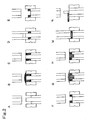
- Figs. 2 illustrate explanatory views of punch
tip operations showing an example of conventional
molded product manufacturing method in which a
plurality of molding materials are localized (shading
as cross section omitted);
- Figs. 3 illustrate explanatory views of punch
tip operations showing an example of problem in the
rubbing-cutting step in the conventional molded
product manufacturing method shown in Fig. 2 in which
a plurality of molding materials are localized
(shading as cross section omitted);
- Figs. 4 illustrate explanatory views of punch
tip operations showing another example of problem in
the rubbing-cutting step in the conventional molded
product manufacturing method shown in Fig. 2 in which
a plurality of molding materials are localized
(shading as cross section omitted);
- Figs. 5 illustrate explanatory views of punch
tip operations showing a first example of
manufacturing steps using the manufacturing apparatus
of the present invention for a molded product
(corresponding to the molded product in Figs. 1)
consisting of a plurality of molded parts part of
whose at least two molded parts faces outside of the
molded product (shading as cross section omitted);
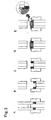
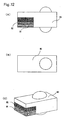
- Figs. 6(A), 6(B) and 6(C) illustrate an
embodiment (second example) of a molded product
manufactured by the manufacturing apparatus of the
present invention, with Fig. 6(A) being a side view,
Fig. 6(B) being a top view, and Fig. 6(C) being a
perspective view;
- Figs. 7 illustrate explanatory views of punch
tip operations showing a second example of
manufacturing steps using the manufacturing apparatus
of the present invention for a molded product
(corresponding to the molded product in Figs. 6)
consisting of a plurality of molded parts part of
whose at least two molded parts faces outside of the
molded product (shading as cross section omitted);
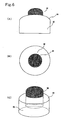
- Figs. 8(A), 8(B) and 8(C) illustrate an
embodiment (third example) of a molded product
manufactured by the manufacturing apparatus of the
present invention, with Fig. 8(A) being a side view,
Fig. 8(B) being a top view, and Fig. 8(C) being a
perspective view;
- Figs. 9 illustrate explanatory views of punch
tip operations showing a third example of
manufacturing steps using the manufacturing apparatus
of the present invention for a molded product
(corresponding to the molded product in Figs. 8)
consisting of a plurality of molded parts part of
whose at least two molded parts faces outside of the
molded product (shading as cross section omitted);
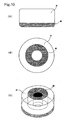
- Figs. 10(A), 10(B) and 10(C) illustrate an
embodiment (fourth example) of a molded product
manufactured by the manufacturing apparatus of the
present invention, with Fig. 10(A) being a side view,
Fig. 10(B) being a top view, and Fig. 10(C) being a
perspective view;
- Figs. 11 illustrate explanatory views of punch
tip operations showing a fourth example of
manufacturing steps using the manufacturing apparatus
of the present invention for a molded product
(corresponding to the molded product in Figs. 10)
consisting of a plurality of molded parts part of
whose at least two molded parts faces outside of the
molded product (shading as cross section omitted);
- Figs. 12(A), 12(B) and 12(C) illustrate an
embodiment (fifth example) of a molded product
manufactured by the manufacturing apparatus of the
present invention, with Fig. 12(A) being a side view,
Fig. 12(B) being a top view, and Fig. 12(C) being a
perspective view;
- Figs. 13 illustrate explanatory views of punch
tip operations showing a fifth example of
manufacturing steps using the manufacturing apparatus
of the present invention for a molded product
(corresponding to the molded product in Figs. 12)
consisting of a plurality of molded parts part of
whose at least two molded parts faces outside of the
molded product (shading as cross section omitted);
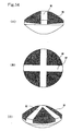
- Figs. 14(A), 14(B) and 14(C) illustrate an
embodiment (sixth example) of a molded product
manufactured by the manufacturing apparatus of the
present invention, with Fig. 14(A) being a side view,
Fig. 14(B) being a top view, and Fig. 14(C) being a
perspective view;
- Figs. 15 illustrate explanatory views of punch
tip operations showing a sixth example of
manufacturing steps using the manufacturing apparatus
of the present invention for a molded product
(corresponding to the molded product in Figs. 14)
consisting of a plurality of molded parts part of
whose at least two molded parts faces outside of the
molded product (shading as cross section omitted);
- Figs. 16(A), 16(B) and 16(C) illustrate an
embodiment (seventh example) of a molded product
manufactured by the manufacturing apparatus of the
present invention, with Fig. 16(A) being a side view,
Fig. 16(B) being a top view, and Fig. 16(C) being a
perspective view;
- Figs. 17 illustrate explanatory views of punch
tip operations showing a seventh example of
manufacturing steps using the manufacturing apparatus
of the present invention for a molded product
(corresponding to the molded product in Figs. 16)
consisting of a plurality of molded parts part of
whose at least two molded parts faces outside of the
molded product (shading as cross section omitted);
- Figs. 18(A), 18(B) and 18(C) illustrate an
embodiment (eighth example) of a molded product
manufactured by the manufacturing apparatus of the
present invention, with Fig. 18(A) being a side view,
Fig. 18(B) being a top view, and Fig. 18(C) being a
perspective view;
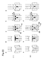
- Figs. 19 illustrate explanatory views of punch
tip operations showing an eighth example of
manufacturing steps using the manufacturing apparatus
of the present invention for a molded product
(corresponding to the molded product in Figs. 18)
consisting of a plurality of molded parts part of
whose at least two molded parts faces outside of the
molded product (shading as cross section omitted);
- Figs. 20(A), 20(B) and 20(C) illustrate an
embodiment (ninth example) of a molded product
manufactured by the manufacturing apparatus of the
present invention, with Fig. 20(A) being a side view,
Fig. 20(B) being a top view, and Fig. 20(C) being a
perspective view;
- Figs. 21 illustrate explanatory views of punch
tip operations showing a ninth example of
manufacturing steps using the manufacturing apparatus
of the present invention for a molded product
(corresponding to the molded product in Figs. 20)
consisting of a plurality of molded parts part of
whose at least two molded parts faces outside of the
molded product (shading as cross section omitted);
- Figs. 22(1) illustrate explanatory views of
punch tip operations when normal lower split punches
are used, and Figs. 22(2) illustrate explanatory
views of punch tip operations when a lower split
punch structure is adopted for reducing residual
molding material on the lower punches in the molding
product manufacturing apparatus according to the
present invention (shading as cross section omitted);
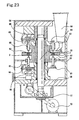
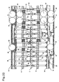
- Fig. 23 illustrates an overall front sectional
view of a common rotary press, although with no
sectional views of punches, vertical shaft and hopper
shown;
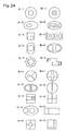
- Figs. 24 illustrate top views of example shapes
of punch tip portions having a split punch structure
used in the present invention, with the shapes
classified into four series A to D according to the
split form;
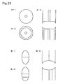
- Figs. 25A to 25E2 illustrate the diversity of
molded products that can be manufactured using a
punch having the single split punch structure in the
present invention, with A showing the shape of a
punch tip portion consists of a double structure, and
series B to E showing a classification of molded
products that can be manufactured from the punch
focusing attention on concave and convex structures
of molded parts provided at the center;
- Figs. 26 illustrate specific examples in which
split punch structures with different split shapes
are used for upper and lower punches in the punches
having the split punch structure used in the present
invention, with Figs. 26A-1 and 26B-1 showing upper
punches, Figs. 26A-2 and 26B-2 showing lower punches,
and Figs. 26A-3 and 26B-3 showing sectional views of
punch tips when tips of upper and lower punches are
brought close to each other as in actual use (shading
showing cross section omitted);
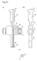
- Figs. 27(A), 27(B) and 27(C) illustrate an
example of punch having the split punch structure
used in the present invention, with Fig. 27(A) being
a vertical sectional view (right half) and schematic
diagram (left half), Fig. 27(B) being a side view,
and Fig. 27(C) being a top view of the punch tip
portion;
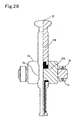
- Fig. 28 illustrates an example of punch having
the split punch structure used in the present
invention, showing a vertical sectional view (right
half) and schematic diagram (left half);
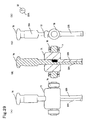
- Figs. 29(A), 29(B), 29(C), and 29(D) illustrate
an example of punch having the split punch structure
used in the present invention, with Fig. 29(A) being
a schematic diagram, Fig. 29(B) being a sectional
view, Fig. 29(C) being a side view, and Fig. 29(D)
being a top view of the punch tip portion;
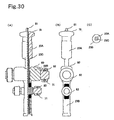
- Figs. 30(A), 30(B) and 30(C) illustrate an
example of punch having the split punch structure
used in the present invention, with Fig. 30(A) being
a vertical sectional view (right half) and schematic
diagram (left half), Fig. 30(B) being a side view,
and Fig. 30(C) being a top view of the punch tip
portion;
- Fig. 31 illustrates a schematic plan view
showing a turn table in an embodiment of the rotary
press of the present invention;
- Fig. 32 illustrates a schematic diagram
including some sectional portion showing the
operation mechanism of the upper and lower punches by
developing the turn table in an embodiment of the
rotary press of the present invention;
- Figs. 33(A) and 33(B) illustrate a residual
molding material removal device of the present
invention, with Fig. 33(A) being a bird's- eye view,
and Fig. 33(B) being a top view;
- Figs. 34(A), 34(B) and 34(C) illustrate an
embodiment (tenth example) of a molded product
manufactured by the manufacturing apparatus of the
present invention, with Fig. 34(A) being a side view,
Fig. 34(B) being a top view, and Fig. 34(C) being a
perspective view;
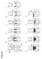
- Figs. 35 illustrate explanatory views of punch
tip operations showing a tenth example of
manufacturing steps using the manufacturing apparatus
of the present invention for a molded product
(corresponding to the molded product in Figs. 34)
consisting of a plurality of molded parts part of
whose at least two molded parts faces outside of the
molded product (shading as cross section omitted);
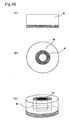
- Figs. 36(A), 36(B) and 36(C) illustrate an
embodiment (eleventh example) of a molded product
manufactured by the manufacturing apparatus of the
present invention, with Fig. 36(A) being a side view,
Fig. 36(B) being a top view, and Fig. 36(C) being a
perspective view;
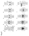
- Figs. 37 illustrate explanatory views of punch
tip operations showing an eleventh example of
manufacturing steps using the manufacturing apparatus
of the present invention for a molded product
(corresponding to the molded product in Figs. 36)
consisting of a plurality of molded parts part of
whose at least two molded parts faces outside of the
molded product (shading as cross section omitted);
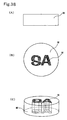
- Figs. 38(A), 38(B) and 38(C) illustrate an
example of molded product of the present invention
whose characters and/or graphics can be externally
identified, with Fig. 38(A) being a side view, Fig.
38(B) being a top view, and Fig. 38(C) being a
perspective view;
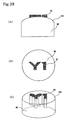
- Figs. 39(A), 39(B) and 39(C) illustrate an
example of molded product of the present invention
whose characters and/or graphics can be externally
identified, with Fig. 39(A) being a side view, Fig.
39(B) being a top view, and Fig. 39(C) being a
perspective view;
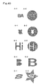
- Figs. 40 illustrate specific examples of punches
having the split punch structure used for
manufacturing a molded product of the present
invention whose characters and/or graphics can be
externally identified, with shapes of split punches
(e.g., center and outer punches) side by side;
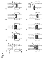
- Figs. 41 illustrate explanatory views of punch
tip operations showing a twelfth example of
manufacturing steps using the manufacturing apparatus
of the present invention for a molded product
(corresponding to the molded product in Figs. 42B-1
and 42B-2) consisting of a plurality of molded parts
part of whose at least two molded parts faces outside
of the molded product (shading as cross section
omitted); and
- Figs. 42A-1 to 42D2 illustrate a molded product
manufactured in the embodiment shown in Figs. 41 and
the diversity of molded products that can be
manufactured by slightly modifying the punch
operations, with Figs. 42A-1 to 42D-1 being sectional
views of molded products, and Figs. 42A-2 to 42D-2
being schematic diagrams of the molded products.
-
BEST MODE FOR CARRYING OUT THE INVENTION
-
In this description, the term "molding material"
is defined as any moldable material including bulk
material while the term "bulk material" as powder,
granules and something similar thereto. In the
present invention, bulk material is preferably used
as molding material.
-
A molded product intended by the present
invention is that which consists of a plurality of
molded parts part of whose at least two molded parts
faces outside of the molded product. In such a
molded product, two or more types of molding
materials are substantially localized respectively as
molded parts, and part of at least two molded parts
thereamong faces outside of the molded product. That
is, ordinary press-coated products, in which one
molded part is entirely covered by another molded
part, are excluded. It should be noted that molded
parts mean individual partial molded bodies making up
the whole of a molded product in the present
specification, with each molded part constituted by a
single molding material, and are produced by
compressing molding materials charged into molds
(including a space surrounded by a die and/or
punches). It should also be noted that if, for
instance, a molding material acquires a new added
value as a result of different physical property
(e.g., particle size, crystal shape) from the
original material despite identical constituents in
terms of chemical substance, the molding material can
be regarded as a different material from the original
material. This holds also true for the case in which
a molded product is claimed to be meaningful as two
separate molded parts by using two perfectly
identical molding materials.
-
A manufacturing apparatus, according to the
present invention that can efficiently mold, in a
single step, a molded product consisting of a
plurality of molded parts part of whose at least two
molded parts faces outside of the molded product, is
a rotary press having a rotatable turn table provided
with a die having a die hole and holding upper and
lower punches above and below the die so as to be
vertically slidable, and being designed to compress
molding materials supplied and charged into the die
by moving the upper and lower punches in mutually
approaching directions and pressing with the punch
tips in a state inserted in the die, the rotary press
being characterized in comprising at least the upper
punch or preferably both the upper and lower punches
split into a plurality of punches, means for moving
the plurality of split punches and allowing
manipulation of at least two of the plurality of
split punches for compression operation, a first
molding material supply-charging unit for supplying
and charging a first molding material into a space in
the die formed above the tip portion of the lower
punch or formed by the tip portions of split punches
of the lower punch, a second molding material supply-charging
unit for supplying and charging a second
molding material into a space formed above and/or
around the first molding material in the die, a
precompression molding unit for compression-molding
at least one of the molding materials supplied and
charged and a main compression molding unit for
compression-molding the entire molded product. The
rotary press comprises, as necessary, a residual
molding material removal unit for removing residual
molding material remaining on the lower punch and/or
the temporary molded product. That is, the apparatus
can perform the steps of supplying and charging a
plurality of molding materials respectively into
intended given spaces, compression-molding at least
one of the molding materials supplied and charged and
compression-molding the entire molded product as
essential steps and may, as necessary, allow
performing the step of removing residual molding
material on the lower punch and/or the temporary
molded product. It should be noted that the space
formed by the tip portions of split punches of the
lower punch split into a plurality of punches refers
to a space formed by moving some of the split punches
of the lower punch.
-
To prevent contamination between molding
materials and ensure clear identification between
molded parts, it is preferred that individual molding
materials be compression-molded every time they are
supplied and charged. For this reason, it is
preferred that the rotary press of the present
invention be normally provided with material supply-charging
units and precompression molding units as
many as the material supply-charging units, in
addition to a main compression molding unit.
-
It should be noted that main compression refers
to a compression operation designed to finally and
completely mold the entire molded product that is
carried out at high compression pressures. On the
other hand, precompression, as opposed to main
compression, refers to all compression operations
carried out at some point before main compression,
and it is preferred that precompression be normally
performed as temporary compression. Temporary
compression denotes compression operation at low
compression pressures. It should be noted that
precompression after supply of the last molding
material is precompression of the entire molded
product, and temporary compression is normally
carried out.
-
When manufacturing a molded product consisting
of a plurality of molded parts part of whose two
molded parts faces outside of the molded product, for
example, the rotary press of the present invention
comprises a first molding material supply-charging
unit for supplying and charging a first molding
material, a precompression molding unit for
compression-molding the first molding material, a
second molding material supply-charging unit for
supplying and charging a second molding material and
a main compression molding unit for compression-molding
the entire molded product and comprises, as
necessary, a residual molding material removal unit
for removing the residual first molding material.
-
If there are a number of molded parts or if
molding materials are localized in a complex manner
within the final molded product, naturally the number
of molding material supply-charging units increases.
Similarly, it is necessary to increase the number of
precompression molding units for compression-molding
molding materials and the number of residual molding
material removal units for removing residual molding
materials as necessary.
-
It can be said that the present invention is
characterized particularly in its embodiments that
contain the step of supplying and charging, onto a
molding material or a molded product consisting
thereof, another molding material. That is, the
rotary press that can perform such a step is
particularly characteristic among the rotary presses
of the present invention.
-
Further in addition to the present invention, a
method and apparatus are disclosed time that can
efficiently localize molding materials in the molded
product in the manufacturing step of supplying and
charging molding materials. Among them is a
provision of a method for pushing up a molded product
(temporary molded product) into a molding material,
further allowing the molded product to penetrate
through the molding material and removing residual
molding material on top, thus localizing the molding
material in a complicated manner and allowing easy
manufacture of the molded product. Also included is
use of lower split punches for reducing the amount of
residual molding material remaining on the lower
punch. That is, the present invention also discloses
a set of upper and lower punches having a split punch
structure, with each tip thereof being split into a
plurality of punches, individual split punches being
vertically slidable and at least two split punches
being manipulatable for compression operation, in
which at least one of the lower split punches is
further split as opposed to the corresponding upper
split punch, in which part or whole of a residual
molding material remaining on the lower punch can be
rubbed and cut by a rubbing-cutting plate as the
split punch is raised and in which, unlike the lower
punch, the upper punch does not have a split form
intended for removing the residual molding material
by rubbing and cutting. The set is, in other words,
a method for reducing a residual molding material in
the compression molding apparatus provided, above and
below the die, with punches having a split punch
structure, with each tip thereof being split into a
plurality of punches, individual split punches being
vertically slidable, and at least two split punches
being manipulatable for compression operation, the
method characterized in that at least one of the
lower split punches is further split as opposed to
the corresponding upper split punch and that part or
whole of a residual molding material remaining on the
lower punch can be rubbed and cut by a rubbing-cutting
plate as the split punch is raised.
-
Next, a specific description is given of steps
for manufacturing a molded product consisting of a
plurality of molded parts part of whose at least two
molded parts faces outside of the molded product
using the rotary press of the present invention. It
should be noted that temporary compression is
employed as precompression in the examples. While
molded products manufactured are shown with a
plurality of molded parts in different colors, this
is for purposes of convenience and clarity, and this
does not necessarily mean that molding materials of
different colors are used as in the invention of
molded products discussed later.
-
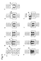
As a first example, a detailed description is
given mainly with reference to Figs. 5. It should be
noted that the molded product is cylindrical in shape
consisting of two types of molding materials, with
one of the molded parts surrounded by another, as
shown in Figs. 1. Both upper and lower punches used
have a double structure in which the tip portion of
one punch is completely enclosed by the tip portion
of the other punch, as shown in Fig. 24A-1.
-
First, with a lower split punch 1B lowered below
the turn table surface (Fig. 5A), a first molding
material M1 is supplied into a first molded part
space 200 above the lower split punch 1B within a die
2 (Fig. 5B). The lower split punch 1B is raised as
necessary, discharging the excess first molding
material M1 out of the die 2 and thus charging a
given amount into the space by rubbing and cutting
(Fig. 5C). Then, an upper split punch 2B and the
lower split punch 1B are moved in mutually
approaching directions for precompression, thus
temporarily molding the first molding material M1
(Fig. 5D). Next, the lower punches are moved to a
given position, with the temporary molded product
from the first molding material M1 held on the lower
split punch 1B (Fig. 5F). A second molding material
M2 is supplied into a second molded part space 201
above a lower punch 1A within the die 2 at a position
where the upper end surface of the temporary molded
product from the first molding material M1 is
slightly lower than the turn table surface (Fig. 5G).
The lower punch or punches (the lower split punch 1A
and/or the lower split punch 1B) are raised as
necessary, discharging the excess second molding
material M2 out of the die 2 and thus ensuring
charging of a given amount into the space by rubbing
and cutting (Fig. 5H). Then, an upper split punch 2A
is moved toward the lower split punch 1A such that
part of the surface of the second molding material M2
is covered (Fig. 5I). Under this condition, the
residual second molding material M2 on the temporary
molded product from the first molding material M1 is
removed (Fig. 5J). In the next compression
operation, compression by moving both upper and lower
split punches at the same speed is not preferred as
this may disturb the distribution of molding
materials within the molded product because of
difference in density between the temporary molded
product from the first molding material M1 and the
second molding material M2. For this reason, the
first molding material M1 is covered by moving the
upper punch (the upper split punch 2B) toward the
lower punch (Fig. 5K), and next the lower split punch
1A is moved toward the upper split punch 2A for
precompression until the punch tip surface of the
lower split punch 1A is aligned with the punch tip
surface of the lower split punch 1B (Fig. 5L). Then,
the upper punches (the upper split punches 2A and 2B)
and the lower punches (the lower split punches 1A and
1B) are moved respectively in mutually approaching
directions for precompression (temporary compression)
of the temporary molded products from the first
molding material M1 and the second molding material
M2 as necessary, eventually followed by main
compression (Fig. 5M). The step shown in Fig. 5N is
for unloading the completed molded product.
-
As a second example, a detailed description will
be given below mainly with reference to Figs. 7. The
molded product is convex in shape, with only the
molded part making up the center portion projecting
on one side, as shown in Figs. 6. The punches used
are the same type as those used in the first example.
-
First, with a lower split punch 3A lowered below
the turn table surface (Fig. 7A), the first molding
material M1 is supplied into a first molded part
space 202 above the lower split punch 3A enclosed by
a lower split punch 3B (Fig. 7B). The lower split
punch 3A is raised as necessary, discharging the
excess first molding material M1 out of the die 2 and
thus ensuring charging of a given amount into the
space by rubbing and cutting (Fig. 7C). Then, an
upper split punch 4A and the lower split punch 3A are
moved in mutually approaching directions for
precompression (Fig. 7D), thus temporarily molding
the first molding material M1. During or after
temporary molding of the first molding material M1,
the residual first molding material M1 remaining on
the lower split punch 3B is removed (Fig. 7E). Next,
with the temporary molded product from the first
molding material M1 held by the lower split punches
3A and 3B, the second molding material M2 is supplied
into a second molded part space 203 above and around
the temporary molded product from the first molding
material M1 within the die 2 (Fig. 7G) by lowering
the lower punch or punches (both the lower split
punches 3A and 3B or the lower split punch 3B) (Fig.
7F). After part of the temporary molded product from
the first molding material M1 is stuck into the
second molding material M2, the excess second molding
material M2 is discharged out of the die 2 as
necessary, thus charging a given amount into the
space by rubbing and cutting (Fig. 7H). It should be
noted that the second molding material M2 can be
supplied after sufficiently lowering the lower split
punch 3B first such that the temporary molded product
from the first molding material M1 is apparently
pushed up. Then, the upper punches (the upper split
punches 4A and 4B) and the lower punches (the lower
split punches 3A and 3B) are moved respectively in
mutually approaching directions for precompression
(temporary compression) of the entire molded product
consisting of the first and second molding materials
as necessary, eventually followed by main compression
(Fig. 7I). The step shown in Fig. 7J is for
unloading the completed molded product.
-
As a third example, a brief description is given
next mainly with reference to Figs. 9. The molded
product is that in which two types of molding
materials are used in the first molded part portion
in the molded product of the second example.
-
Although the third example is basically only a
repetition of supply of the first molding material in
the second example, the first molding material M1
need not always be compression-molded in Figs. 9D and
9E, and it suffices to only slightly press the
surface of the first molding material M1 with an
upper split punch 6A in order to allow removal of
residual molding material. To prevent contamination
between the first and second molding materials M1 and
M2, however, it is preferred that compression molding
of the first molding material M1 be carried out.
-
As a fourth example, a detailed description will
be given below mainly with reference to Figs. 11.
The molded product is donut-shaped, with a molding
material making up one of the surfaces of the
cylindrical structure also existing at the center
portion of the molded product, as shown in Figs. 10.
While the punches used are of the type in which the
tip portion of one punch completely encloses the tip
portions of other punches, as shown in Fig. 24B-1,
the upper punches have a double structure with a
hollow at the center while the lower punches a triple
structure with a split punch provided at the center.
It should be noted that a lower split punch 7C does
not perform compression operation.
-
First, with a lower split punch 7B lowered below
the turn table surface (Fig. 11A), the first molding
material M1 is supplied into a first molded part
space 204 above the lower split punch 7B enclosed by
the die 2 and a lower split punch 7A (Fig. 11B). The
lower split punch 7B is raised as necessary,
discharging the excess first molding material M1 out
of the die 2 and thus ensuring charging of a given
amount into the space by rubbing and cutting (Fig.
11C). Then, an upper split punch 8B and the lower
split punch 7B are moved in mutually approaching
directions for precompression (Fig. 11D), thus
temporarily molding the first molding material M1.
It should be noted that the tip surface of the lower
split punch 7C is always level with the turn table
unless otherwise required and may allow compression
operation even if fixed in this state. Next, after
temporary molding of the first molding material M1,
the residual first molding material M1 remaining on
the lower split punch 7A is removed (Fig. 11E). With
the temporary molded product from the first molding
material M1 held on the lower split punch 7B, the
second molding material M2 is supplied into a second
molded part space 205 above and inside the temporary
molded product from the first molding material M1
within the die 2 (Fig. 11G) by lowering the lower
punches (the lower split punches 7A and 7C or the
lower split punches 7A, 7B and 7C) (Fig. 11F). The
lower split punch 7C is raised to its initial
position (Fig. 11H), discharging the excess second
molding material M2 out of the die 2 as necessary and
thus ensuring charging of a given amount into the
space by rubbing and cutting (Fig. 11I). Then, the
upper punches (the upper split punches 8A and 8B) and
the lower punches (the lower split punches 7A and 7B)
are moved respectively in mutually approaching
directions for precompression (temporary compression)
of the entire molded product consisting of the first
and second molding materials as necessary, eventually
followed by main compression (Fig. 11J). The step
shown in Fig. 11K is for unloading the completed
molded product.
-
As a fifth example, a detailed description will
be given below mainly with reference to Figs. 13.
The molded product consists of three types of molding
materials, with a protrusion on both surfaces of a
rectangular parallelepiped, as shown in Figs. 12.
The punches used have a rectangular tip surface split
into two, with a recess provided on one side for
forming protrusions (Fig. 24 D-4).
-
First, with a lower split punch 9A lowered below
the turn table surface (Fig. 13A), the first molding
material M1 is supplied into a first molded part
space 206 above the lower split punch 9A and enclosed
by the die 2 and a lower split punch 9B (Fig. 13B).
The lower split punch 9A is raised as necessary,
discharging the excess first molding material M1 out
of the die 2 and thus ensuring charging of a given
amount into the space by rubbing and cutting (Fig.
13C). Then, an upper split punch 10A and the lower
split punch 9A are moved in mutually approaching
directions for precompression (Fig. 13D), thus
temporarily molding the first molding material M1.
During or after temporary molding of the first
molding material M1, the residual first molding
material M1 remaining on the lower split punch 9B is
removed (Fig. 13E). Next, the second molding
material M2 is supplied (Fig. 13G) into a second
molded part space 207 (Fig. 13F) above the temporary
molded product from the first molding material held
on the lower split punch 9A within the die 2. The
lower split punch 9A is raised as necessary,
discharging the excess second molding material M2 out
of the die 2 and thus ensuring charging of a given
amount into the space by rubbing and cutting (Fig.
13H). Then, the upper split punch 10A and the lower
split punch 9A are moved in mutually approaching
directions for precompression (Fig. 13I), thus
temporarily molding the second molding material M2
together with the temporary molded product from the
first molding material M1. During or after temporary
molding of the second molding material M2 (and the
first molding material M1), the residual second
molding material M2 remaining on the lower split
punch 9B is removed (Fig. 13J). Further, with the
lower punch or punches (the lower split punches 9A
and 9B or the lower split punch 9B) lowered, a third
molding material M3 is supplied (Fig. 13L) into a
third molded part space 208 (Fig. 13K) above the
temporary molded products from the first and second
molding materials M1 and M2 and on the lower split
punch 9B within the die 2. The excess third molding
material M3 is discharged out of the die 2 as
necessary, thus ensuring charging of a given amount
into the space by rubbing and cutting (Fig. 13M).
Finally, the upper punches (the upper split punch 10A
and an upper split punch 10B) and the lower punches
(the lower split punches 9A and 9B) are moved in
mutually approaching directions for precompression
(temporary compression) of the entire molded product
consisting of the first, second and third molding
materials, eventually followed by main compression
(Fig. 13N). The step shown in Fig. 130 is for
unloading the completed molded product. It should be
noted that it is possible for the first molding
material M1 to proceed with the step of removing the
residual first molding material by lightly pressing
down the surface of the first molding material M1
without precompression thereof.
-
As a sixth example, a detailed description will
be given below mainly with reference to Figs. 15.
The molded product is, with one molding material
split into four parts and localized on one of the
disc-shaped surfaces, as shown in Figs. 14. Both
upper and lower punches used have a split structure
as shown in Fig. 24D-1, with one of the split punches
having a tip portion split into four parts by the
other split punch - a cross-shaped split punch.
-
First, with a lower split punch 11B lowered
below the turn table surface (Fig. 15A), the first
molding material M1 is supplied into a first molded
part space 209 enclosed by the die 2 and a lower
split punch 11A above the lower split punch 11B
(Fig. 15B). The lower split punch 11B is raised as
necessary, discharging the excess first molding
material M1 out of the die 2 and thus ensuring
charging of a given amount into the space by rubbing
and cutting (Fig. 15C). Then, the upper split punch
12B and the lower split punch 11B are moved in
mutually approaching directions for precompression
(Fig. 15D), thus temporarily molding the first
molding material M1. After temporary molding of the
first molding material M1, the residual first molding
material M1 remaining on the lower split punch 11A is
removed (Fig. 15E). With the temporary molded
product from the first molding material M1 held on
the lower split punch 11B, the second molding
material M2 is supplied into a second molded part
space 210 above and around the temporary molded
product from the first molding material M1 within the
die 2 (Fig. 15G) by lowering the lower punches (the
lower split punches 11A and 11B or the lower split
punch 11A) (Fig. 15F). The excess second molding
material M2 is discharged out of the die 2 as
necessary, thus ensuring charging of a given amount
into the space by rubbing and cutting (Fig. 15H).
Then, the upper punches (the upper split punches 12A
and 12B) and the lower punches (the lower split
punches 11A and 11B) are moved respectively in
mutually approaching directions for precompression
(temporary compression) of the entire molded product
consisting of the first and second molding materials
as necessary, eventually followed by main compression
(Fig. 15I). The step shown in Fig. 15J is for
unloading the completed molded product.
-
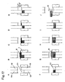
As a seventh example, a detailed description
will be given below mainly with reference to Figs.
17. The molded product is disc-shaped, with one of
the surfaces split into two parts along the diameter,
as shown in Figs. 16. The punches used have a
circular tip surface split into two parts, as shown
in Fig. 24D2.
-
First, with a lower split punch 13A lowered
below the turn table surface (Fig. 17A), the first
molding material M1 is supplied into a first molded
part space 211 enclosed by the die 2 and a lower
split punch 13B and above the lower split punch 13A
(Fig. 17B). The lower split punch 13A is raised as
necessary, discharging the excess first molding
material M1 out of the die 2 and thus ensuring
charging of a given amount into the space by rubbing
and cutting (Fig. 17C). Then, the upper split punch
14A and the lower split punch 13A are moved in
mutually approaching directions for precompression
(Fig. 17D), thus temporarily molding the first
molding material M1. During or after temporary
molding of the first molding material M1, the
residual first molding material M1 remaining on the
lower split punch 13B is removed (Fig. 17E). Next,
with the temporary molded product from the first
molding material M1 held by the lower split punches
13A and 13B, the second molding material M2 is
supplied into a second molded part space 212 above
the temporary molded product from the first molding
material M1 and above the lower split punch 13B
within the die 2 (Fig. 17G) by lowering the lower
punch or punches (both the lower split punches 13A
and 13B or the lower split punch 13B) (Fig. 17F).
The excess second molding material M2 is discharged
out of the die 2 as necessary, thus ensuring charging
of a given amount into the space by rubbing and
cutting (Fig. 17H). Then, the upper punches (the
upper split punches 14A and 14B) and the lower
punches (the lower split punches 13A and 13B) are
moved respectively in mutually approaching directions
for precompression (temporary compression) of the
entire molded product consisting of the first and
second molding materials as necessary, eventually
followed by main compression (Fig. 17I). The step
shown in Fig. 17J is for unloading the completed
molded product.
-
As an eighth example, a detailed description
will be given below mainly with reference to Figs.
19. The molded product is convex in shape, with the
center portion projecting and further the projecting
portion and the bottom portion being made of the same
molding material, as shown in Figs. 18. The punches
used are the same as those used in the first example.
-
First, with a lower split punch 15A lowered
below the turn table surface (Fig. 19A), the first
molding material M1 is supplied into a first molded
part space 213 enclosed by a lower split punch 15B
and above the lower split punch 15A (Fig. 19B). The
lower split punch 15A is raised as necessary,
discharging the excess first molding material M1 out
of the die 2 and thus ensuring charging of a given
amount into the space by rubbing and cutting (Fig.
19C). Then, the upper split punch 16A and the lower
split punch 15A are moved in mutually approaching
directions for precompression (Fig. 19D), thus
temporarily molding the first molding material M1.
During or after temporary molding of the first
molding material M1, the residual first molding
material M1 remaining on the lower split punch 15B is
removed (Fig. 19E). Next, with the temporary molded
product from the first molding material M1 held on
the lower split punch 15A, the second molding
material M2 is supplied into a second molded part
space 214 above and around the temporary molded
product from the first molding material M1 within the
die 2 (Fig. 19G) by lowering the lower punch or
punches (both the lower split punches 15A and 15B or
the lower split punch 15B) (Fig. 19F). After part of
the temporary molded product from the first molding
material M1 is stuck into the second molding material
M2 (Fig. 19H), the excess second molding material M2
is discharged out of the die 2 as necessary, thus
ensuring charging of a given amount into the space by
rubbing and cutting (Fig. 19I). It should be noted
that the second molding material M2 can be supplied
after sufficiently lowering the lower split punch 15B
first such that the temporary molded product from the
first molding material M1 is apparently pushed up.
Then, the upper split punch 16B and the lower split
punch 15B are moved respectively in mutually
approaching directions for precompression of the
second molding material (Fig. 19J) followed by
raising of the upper punch, thus removing the second
molding material M2 remaining on the temporary molded
product from the first molding material M1 (Fig.
19K). In the removal of the molding material, only
the uncompressed second molding material M2 on the
temporary molded product from the first molding
material M1 is removed while other portions remain
unremoved because they have been compression-molded.
Next, the third molding material M3 is supplied into
a third molded part space 215 above the temporary
molded products from the first and second molding
materials M1 and M2 within the die 2 (Fig. 19M). The
excess third molding material M3 is discharged out of
the die 2 as necessary, thus ensuring charging of a
given amount into the space by rubbing and cutting
(Fig. 19N). Then, the upper punches (the upper split
punches 16A and 16B) and the lower punches (the lower
split punches 15A and 15B) are moved respectively in
mutually approaching directions for precompression
(temporary compression) of the entire molded product
consisting of the first, second and third molding
materials as necessary, eventually followed by main
compression (Fig. 19O). The step shown in Fig. 19P
is for unloading the completed molded product.
-
It should be noted that although the same
material is used for the third molding material M3 as
for the first molding material M1, these materials
are described as separate materials for reasons of
convenience. It is of course possible to use a
completely different molding material for the third
molding material M3 from those of the first and
second molding materials M1 and M2.
-
It should be also noted that a method is
provided in the eighth example for localizing a
molding material in a complex manner and allowing
easy manufacture of the molded product by pushing up
a temporary molded product into the molding material,
allowing the molded product to penetrate through the
molding material and thereby removing the residual
molding material on top, as shown in Figs. 19G to
19L, as a method for efficiently localizing molding
materials in a molded product. The method is
possible only if a residual molding material removal
device is available, and a detailed description
thereof will be given later.
-
As a ninth example, a detailed description will
be given below mainly with reference to Figs. 21.
The molded product is disc-shaped, with two molded
parts provided on the right and left sides separately
from each other, as shown in Figs. 20. The punches
used are the same as those used in the seventh
example.
-
First, with a lower split punch 17A lowered
below the turn table surface (Fig. 21A), the first
molding material M1 is supplied into a first molded
part space 216 enclosed by a lower split punch 17B
and the die 2 and above the lower split punch 17A
(Fig. 21B). The lower split punch 17A is raised as
necessary, discharging the excess first molding
material M1 out of the die 2 and thus ensuring
charging of a given amount into the space by rubbing
and cutting (Fig. 21C). Then, the upper split punch
18A and the lower split punch 17A are moved in
mutually approaching directions for precompression
(Fig. 21D), thus temporarily molding the first
molding material M1. During or after temporary
molding of the first molding material M1, the
residual first molding material M1 remaining on the
lower split punch 17B is removed (Fig. 21E). Next,
with the temporary molded product from the first
molding material M1 held by the lower split punches
17A and 17B, the second molding material M2 is
supplied into a second molded part space 217 above
the temporary molded product from the first molding
material M1 within the die 2 (Fig. 21G) by lowering
the lower punch or punches (both the lower split
punches 17A and 17B or the lower split punch 17B)
(Fig. 21F). The excess second molding material M2 is
discharged out of the die 2 as necessary, thus
ensuring charging of a given amount into the space by
rubbing and cutting (Fig. 21H). Further, the second
molding material M2 remaining on the surface of the
temporary molded product from the first molding
material M1 on the lower split punch 17A is removed,
with the charged second molding material M2 lightly
covered by an upper split punch 18B (Fig. 21I).
Then, the upper split punch 18A is lowered onto the
molded product such that the tips of the upper split
punches are aligned with each other, followed by
precompression of the second molding material M2 by
the lower split punch 17B and the upper split punch
18B (Fig. 21J). Further, the upper punches (the
upper split punches 18A and 18B) and the lower
punches (the lower split punches 17A and 17B) are
moved respectively in mutually approaching directions
for precompression (temporary compression) of the
entire molded product consisting of the first and
second molding materials as necessary, eventually
followed by main compression (Fig. 21K). The step
shown in Fig. 21L is for unloading the completed
molded product.
-
It should be noted that the residual molding
material removal step can be carried out by
compressed air injection and suction (device shown in
Figs. 33), brushing, scraper, etc. or a device
equipped with a combination thereof in any one of the
embodiments. A detailed description will be given
later. It should be also noted that, depending on
the punch shapes, the residual molding material
removal step can be carried out concurrently with the
compression step in some cases while the step can
only be performed at the completion of the
compression step in other cases. If the compression
step is skipped, the residual molding material
removal step is carried out with the surface of the
molding material lightly pressed down by the punch.
-
While the embodiments requiring the residual
molding material removal step have been described so
far, an embodiment not requiring the step will be
presented next. As a tenth example, a detailed
description will be given below mainly with reference
to Figs. 35. The molded product is cylindrical in
shape and made up of two types of molding materials,
with one of the molded parts making up one of the
surfaces and the core of the molded product
surrounded by the other molded part, as shown in
Figs. 34. Both upper and lower punches used have a
double structure in which the tip portion of one
punch is completely enclosed by the tip portion of
the other punch, as shown in Fig. 24A-1.
-
First, with a lower split punch 21B lowered
below the turn table surface (Fig. 35A), the first
molding material M1 is supplied into a first molded
part space 220 above a lower split punch 21B within
the die 2 (Fig. 35B). The lower split punch 21B is
raised as necessary, discharging the excess first
molding material M1 out of the die 2 and thus
ensuring charging of a given amount into the space by
rubbing and cutting (Fig. 35C). Then, an upper split
punch 22B and the lower split punch 21B are moved in
mutually approaching directions for precompression,
thus temporarily molding the first molding material
M1 (Fig. 35D). Next, the lower punches are moved to
a given position, with the temporary molded product
from the first molding material M1 held on the lower
split punch 21B (Fig. 35F). The second molding
material M2 is supplied into a second molded part
space 221 above a lower punch 21A and above the
temporary molded product from the first molding
material M1 within the die 2 at a position where the
upper end surface of the temporary molded product
from the first molding material M1 is slightly lower
than the turn table surface (Fig. 35G). The lower
punch or punches (the lower split punch 21A and/or
the lower split punch 21B) are raised as necessary,
discharging the excess second molding material M2 out
of the die 2 and thus ensuring charging of a given
amount into the space by rubbing and cutting (Fig.
35H). In the next compression operation, compression
by moving both upper and lower split punches at the
same speed is not preferred as this may disturb the
distribution of molding materials within the molded
product because of difference in density between the
temporary molded product from the first molding
material M1 and the second molding material M2. For
this reason, the first molding material M1 is covered
by moving the upper punches (an upper split punch 22A
and the upper split punch 22B) toward the lower
punches, and next the lower split punch 21A is moved
toward the upper split punch 22A for precompression
until the punch tip surface of the lower split punch
21A is aligned with the punch tip surface of the
lower split punch 21B (Fig. 35I). Further, the upper
punches (the upper split punches 22A and 22B) and the
lower punches (the lower split punches 21A and/or
21B) are moved in mutually approaching directions for
precompression (temporary compression) of the
temporary molded products from the first and second
molding materials M1 and M2, eventually followed by
main compression (Fig. 35J). The step shown in Fig.
35K is for unloading the completed molded product.
-
As an eleventh example, a detailed description
will be given below mainly with reference to Figs.
37. The molded product is donut-shaped, with a
molding material making up one of the surfaces of the
cylindrical structure also existing at the center
portion of the molded product, as shown in Figs. 36.
While the punches used are of the type in which the
tip portions of other punches are completely enclosed
by the tip portion of one punch, as shown in Fig.
24B-1, the upper punches have a double structure with
a hollow at the center. The lower punches have a
triple structure with a split punch also provided at
the center. It should be noted that a lower split
punch 23C does not perform compression operation.
-
First, with a lower split punch 23B lowered
below the turn table surface (Fig. 37A), the first
molding material M1 is supplied into a first molded
part space 222 enclosed by the die 2 and a lower
split punch 23A and above the lower split punch 23B
(Fig. 37B). The lower split punch 23B is raised as
necessary, discharging the excess first molding
material M1 out of the die 2 and thus ensuring
charging of a given amount into the space by rubbing
and cutting (Fig. 37C). Then, an upper split punch
24B and the lower split punch 23B are moved in
mutually approaching directions for precompression
(Fig. 37D), thus temporarily molding the first
molding material M1. It should be noted that the tip
surface of the lower split punch 23C is always level
with the turn table unless otherwise required and may
allow compression operation even if fixed in this
state. Next, with the temporary molded product from
the first molding material M1 held on the lower split
punch 23B, the second molding material M2 is supplied
into a second molded part space 223 above and inside
the temporary molded product from the first molding
material M1 within the die 2 (Fig. 37F) by lowering
the lower punches (the lower split punches 23A and
23C or the lower split punches 23A, 23B and 23C)
(Fig. 37E). The lower split punch 23C is raised to
its initial position (Fig. 37G), discharging the
excess second molding material M2 out of the die 2 as
necessary and thus ensuring charging of a given
amount into the space by rubbing and cutting (Fig.
37H). Then, the upper punches (an upper split punch
24A and the upper split punch 24B) and the lower
punches (the lower split punches 23A and 23B) are
moved respectively in mutually approaching directions
for precompression (temporary compression) of the
entire molded product consisting of the first and
second molding materials as necessary, eventually
followed by main compression (Fig. 37I). The step
shown in Fig. 37J is for unloading the completed
molded product.
-
From here, a description will be further given
of the case in which a normal punch not having a
split punch structure is used as the lower punch.
The present embodiment will be explained below in
detail as a twelfth example mainly with reference to
Figs. 41. The molded product is cylindrical in
shape, with the center portion of a molded part
making up one of the surfaces projecting outward and
the molded part further projecting into the molded
product toward the center thereof, as shown in Figs.
42B. While the punches used are of the type in which
the tip portion of one punch is completely enclosed
by the tip portion of the other punch, as shown in
Fig. 24A-1, the upper punch has a double structure
while a normal punch with no split structure is used
as the lower punch.
-
First, with a lower punch 25A lowered below the
turn table surface (Fig. 41A), the first molding
material M1 is supplied into a first molded part
space 224 enclosed by the die 2 and the lower punch
25A and above a lower split punch 25B (Fig. 41B).
The lower punch 25A is raised as necessary,
discharging the excess first molding material M1 out
of the die 2 and thus ensuring charging of a given
amount into the space by rubbing and cutting (Fig.
41C). Then, with an upper split punch 26A projecting
beyond an upper split punch 26B, the upper split
punches 26A and 26B and the lower punch 25A are moved
in mutually approaching directions for precompression
(Fig. 41D), thus temporarily molding the first
molding material M1. Next, with the temporary molded
product from the first molding material M1 held on
the lower punch 25A, the second molding material M2
is supplied into a second molded part space 225 above
the temporary molded product from the first molding
material M1 within the die 2 (Fig. 41F) by moving the
lower punch 25A to a given position (Fig. 41E). The
lower punch 25A is raised to a given position as
necessary, discharging the excess second molding
material M2 out of the die 2 and thus charging a
given amount into the space by rubbing and cutting
(Fig. 41G). Then, with the upper split punch 26B
projecting beyond the upper split punch 26A, the
upper punches and the lower punch 25A are moved in
mutually approaching directions for precompression
(temporary compression) of the entire molded product
consisting of the first and second molding materials
as necessary, eventually followed by main compression
(Fig. 41M). The step shown in Fig. 41N is for
unloading the completed molded product.
-
Manufacturing steps have been described so far
in relation to various embodiments of the method for
manufacturing a molded product consisting of a
plurality of molded parts part of whose at least two
molded parts faces outside of the molded product
using the rotary press of the present invention. The
rotary press of the present invention is constructed
to allow performance of the manufacturing steps in
order to manufacture a molded product consisting of a
plurality of molded parts part of whose at least two
molded parts faces outside of the molded product.
From here onwards, conventional rotary press will be
described first followed by a detailed description of
structural portions of the manufacturing apparatus
which is the rotary press of the present invention.
-
If shaft-driven, for example, rotary press often
has a vertical shaft 58, supported by a bearing 57,
arranged at the center portion of a main body frame
56, with a motor 59 transmitting rotational drive
force to the vertical shaft and a turn table 1 fixed
near the vertical shaft (Fig.23). Further, there are
provided an upper punch holding portion 60, located
on the upper portion of the turn table 1, for holding
an upper punch so as to be vertically slidable and a
lower punch holding portion 61, located on the lower
portion of the turn table 1, for holding a lower
punch so as to be vertically slidable such that the
turn table 1 is sandwiched between the upper and
lower punch holding portions 60 and 61. On the turn
table 1, there is a die portion made up of a
plurality of a die mounting hole 62, for fitting the
die 2 so as to be slidable, that are provided along
the same circumference. On each of the upper and
lower punch holding portions 60 and 61, there are a
plurality of punch holding hole 63 drilled for
holding the upper and lower punches so as to be
slidable. Each of the punch holding hole 63 and the
die mounting hole 62 is drilled on the turn table
such that the lower punch 64, the upper punch 65 and
the die 2 are arranged vertically with their center
lines aligned. Tracks 66 are provided
correspondingly for track contact portions of the
upper punch 65 and the lower punch 64, and the
punches move vertically on the tracks as they engage
with and are guided by respective cams which will be
discussed later. The die 2 has a die hole 67 cut
vertically through the die into which the tips of the
upper and lower punches 65 and 64 are inserted. It
should be noted that 68 represents a compression
roller while 69 a hopper in Fid. 23. In addition to
shaft-driven rotary press, there are other types of
rotary presses such as external gear-driven (external
gear type) rotary press in which rotational drive
force is transmitted by equipping the turn table with
a gear and also internal gear-driven (internal gear
type) rotary press.
-
Next, a description will be given of the punches
having a multi-split structure used in the present
invention and the portions associated therewith.
-
The rotary press of the present invention is
constructed to have at least the upper punch or
preferably both upper and lower punches split into a
plurality of punches. Various split forms of the
punch tip portions are shown in Figs. 24. For
instance, Figs. 24A illustrate punches, each of which
consists of two split punches with the tip portions
thereof also split into two parts and in which the
tip portion of one punch is completely enclosed by
the tip portion of the other punch. Figs. 24B
illustrate punches, each of which consists of two or
more split punches with their tip portions also split
into three or more parts and in which the tip portion
of one punch completely encloses the tip portions of
other punches. Figs. 24C illustrate punches, each of
which consists of two or more split punches and in
which the tip portions of at least two punches are
not completely enclosed by the tip portion of other
punch. Figs. 24D illustrate punches, each of which
consists of two or more split punches and in which
the tip portions of none of the punches are enclosed
by the tip portion of other punch. It is to be
understood that while some of the punches of Figs.
24B to 24D consist of the same number of split
punches as the number of divisions of the tip
portion, others take on the form in which only the
tip portion of one split punch is split further.
Although the aforementioned forms represent typical
split forms of the punch tip portions, split forms
are not limited thereby.
-
While individual split punches that are separate
from one another commonly take on the split form in
which the upper and lower punches can perform
compression in a mutually responsive fashion, the
split patterns of the upper and lower punches do not
necessarily need to coincide with each other, and the
number of divisions and the split shapes of the upper
and lower punches may differ from each other. The
split patterns of the upper and lower punches are
changed for different reasons including changing the
split shapes in accordance with the target molded
product shape or the arrangement of a plurality of
individual ingredients and splitting the lower punch
further to reduce the amount of residual molding
materials. Among specific examples are the upper and
lower punches in which one of the split punches
encloses the other split punch or punches as shown in
Figs. 26A with the upper punch split into two parts
and the lower punch into three parts, those in which
while the upper punch is only split into two
semicircles, one of the semicircles of the lower
punch is further split into two punches as shown in
Figs. 26B and those used for example in Figs. 11 in
which the upper punch has a double structure with a
hollow at the center while the lower punch has a
triple structure with no hollow. In any case, the
number of divisions and the split shapes are not
limited so long as the upper and lower punches can
perform compression operation in the compression step
using individual split punches making up the upper
and lower punches and the combination thereof.
Alternatively, it is possible to manipulate the
molded product shape by using the lower punch with no
split structure and the upper punch with a split
structure.
-
A description will be given of the upper and
lower punches both having a split structure but
differing in split shape mainly with reference to
Figs. 26. Fig. A-1 shows an upper punch, Fig. A-2 a
lower punch and Fig. A-3 a sectional view of the
punch tips when the upper and lower punches of Figs.
A-1 and A-2 are brought close to each other in the
condition adhering to the actual usage (shading
representing cross section omitted). The same holds
true for Figs. B-1 to B-3. In this case, the main
purpose of having different split shapes for the
upper and lower punches lies in reducing the amount
of residual molding material on the lower punch
rather than localizing the molding material. To
reduce the amount of residual molding material on the
lower punch, the lower punch is split into more parts
than the upper punch, thus reducing the residual
molding material on the lower punch not removable
with the rubbing-cutting plate. For instance, Figs.
26A-1 to 26A-3 correspond to Figs. 22(2). As is
apparent from comparison between Figs. 22(1) and
Figs. 22(2), a split punch is used for the portion
capable of forming the same plane as the turn table,
allowing removal of excess molding material from the
portions by the rubbing-cutting plate as the split
punch is raised to the same plane as the turn table
and thereby reducing the absolute amount of residual
molding material. Here, the two punch tip portions
(20B1, 20B2) for removing excess molding material
make up a single split punch. Further, if the punch
tips consist entirely of curving surfaces as shown in
Figs. 26B-1 to 26B-3, it is impossible for the lower
punch to form the same plane as the turn table.
However, removal of excess molding material by the
rubbing-cutting plate is possible by raising some of
the lower split punches to the proximity of the turn
table, thus reducing the absolute amount of residual
molding material. That is, the present method for
splitting punches does not require the lower punch to
take on the split form that allows formation of the
same plane as the turn table. It suffices to use the
split form that allows reduction of the absolute
amount of residual molding material by the rubbing-cutting
plate, and the number of divisions is not
specifically limited. For example, the lower punch
shown in Figs. 26B-1 to 26B-3 consists of three split
punches, with the split form not being evenly split
with respect to the longer diameter. The reason is
that if the purpose is to remove molding material
remaining on one of the split punches, then splitting
the other split punch further or evenly splitting the
lower punch is meaningless (Fig.17D, Fig.21D).
-
Split punches used in the present invention can
be grouped under five types in terms of split form of
the upper and lower punches as follows. (1) Both of
the upper and lower punches consist of two split
punches, with the tip portion of one of the split
punches completely enclosing the tip portion of the
other punch. (both upper and lower punches with a
double structure) (2) Either of the upper and lower
punches consists of three or more split punches, with
the tip portion of one of the split punches
completely enclosing the tip portions of the other
punches. (3) At least two of the tip portions of
either of the upper and lower punches are not
completely enclosed by the other split punches. (4)
The tip portions of none of the punches of both the
upper and lower punches are enclosed by the tip
portions of the other punches. (5) The lower punch
is a normal punch with no split structure.
-
A description has been given so far focusing on
punch split forms. Diversity of molded products will
be described below that can be manufactured by the
rotary press of the present invention and the
aforementioned punches. As is evident from the punch
split forms and punch structures, punches consisting
of a single split form are capable of manufacturing a
variety of molded products of different forms. The
reason is that while shape change beyond the die
inner diameter is impossible as with common presses,
variations can be added to molded products, as far as
the vertical direction with respect to the punch
surface is concerned, by the amount and type of
molding material charged, or repetition thereof or
the method for setting a space into which molding
material is to be charged. Further, the respective
split punches of the punches in the rotary press of
the present invention having a split punch structure
are slidable and at least two thereof are
manipulatable for compression operation, considerably
enhancing variations as compared with conventional
non-split punches.
-
One of such examples is shown in Figs. 25. Fig.
25A illustrates a punch tip surface in which the tip
portion of one of the punches completely encloses the
tip portion of the other punch (same as Fig. 24A-1).
Next, Figs. 25B-1 to 25E-2 show modes of the molded
products that can be manufactured with the punch
having the split form. Those shown in Figs. 25B-1 to
25B-3 are molded products consisting of a plurality
of molded parts with no concave or convex structure
on either of the surfaces of the cylindrical
structure. In detail, these figures show: a molded
product in which the molding material located at the
center stretches to both surfaces of the cylinder
(25B-1, same as Figs. 1) ; another molded product in
which the molding material stretches to only one of
the cylinder surfaces (25B-2) and still another
molded product in which the molding material
stretches to both surfaces of the cylinder but is
separated within the molded product (Fig. 25B-3).
Figs. 25C-1 to 25C-3 show molded products consisting
of a plurality of molded parts with a convex
structure on one of the surfaces of the cylindrical
structure: a molded product in which a molding
material located at the center stretches to the
opposite surface of the cylinder (25C-1); another
molded product in which the molding material stops
halfway within the cylindrical molded product (25C-2)
and still another molded product in which the molding
material exists only on top of the cylindrical molded
product (25C-3). Figs. 25D-1 and 25D-2 show molded
products consisting of a plurality of molded parts
with a convex structure on both surfaces of the
cylindrical structure: a molded product in which a
molding material located at the center stretches to
the opposite surface of the cylinder (25D-1) and
another molded product in which the molding material
exists on both surfaces but is separated within the
cylindrical molded product (25D-2). Figs. 25E-1 and
25E-2 show molded products consisting of a plurality
of molded parts with a concave structure on either of
the surfaces of the cylindrical structure: a molded
product in which a molding material located at the
center stops halfway within the molded product (25E-1)
and another molded product in which the other
surface has a convex structure consisting of the same
molding material. In addition to the above, a
variety of other molded products can be manufactured
such as those having a concave structure on both
surfaces and that including three or more molding
materials. Thus, punches made up of a single split
form are capable of manufacturing a variety of molded
products of different forms, and this holds true for
all other punches shown in Figs. 24.
-
It is to be understood that there are also a
considerably large number of variations in moldable
molded products in particular in the case of the
lower punch being a normal punch with no split
structure. One example is shown in Figs. 42. These
molded products are also shaped in such a manner as
to combine large and small cylindrical structures and
consist of a plurality of molded parts with a convex
or concave structure on either of the surfaces as
with the aforementioned molded products. In detail,
Figs. 42A show a molded product that has a combined
structure of a cylindrical molded part with a convex
structure on one of the surfaces and another
cylindrical molded part with no concave or convex
structure. Figs. 42B show a molded product that,
although having a structure similar to that of Figs.
42A, has a cylindrical molded part with a convex
structure further having a convex structure on the
junction surface within the molded product. Figs.
42C show a molded product that consists of a
cylindrical molded part with a concave structure on
one of the surfaces of the cylindrical structure and
another cylindrical molded part with no concave or
convex structure. Figs. 42D show a cylindrical
molded product that has a three-layer structure in
which a molded part is added on top of the molded
product of Figs. 42A and has no concave or convex
structure as a whole.
-
In the present invention, it is absolutely
essential that all individual split punches making up
a punch be slidable and that at least two of the
split punches making up a punch be manipulatable for
compression operation. As an example, a punch is
shown in Figs. 27 that corresponds to the series of
punches in Figs. 24A and consists of two split
punches in which the tip portion of one of the
punches completely encloses the tip portion of the
other punch. It is to be noted that, from here
onwards, the split punches are called split A and B
punches for convenience. The punch comprises a split
A punch 3A, a split B punch 3B, a split A punch
compression head (substantially the same location as
the bottom portion of the split A punch) 25, a split
B punch compression head 70 and a split B punch
vertical sliding motion adjustment roller 23. The
compression step is carried out by pressing the split
A punch compression head 25 with compression rollers
(29, 31, 35 in Fig.32) and further by pressing the
split B punch compression head 70 with compression
rollers (33, 37 in Fig. 32). Manipulation of the
split A and B punches for compression operation is
thus achieved. It is to be noted that the portions
of the split A and B punches in contact with the
compression rollers (the split B punch compression
head 70 and the split A punch compression head 25)
are separated vertically, thus preventing the
compression rollers for the split A and B punches
from interfering with one another.
-
While the vertical sliding motion of the split A
punch is controlled by a normal method mainly using a
split A punch track and the bottom portion thereof
(split A punch compression head) 25, the vertical
sliding motion adjustment roller 23 is provided that
comes in direct contact with a split B punch track to
allow vertical sliding motion of the split B punch.
Preferably, a plurality of bearings 71 are provided
within the rollers to allow rotation of the rollers
and smooth vertical sliding motion of the split B
punch. Here, the vertical sliding motion adjustment
roller 23 is arranged outside the split B punch
compression head 70, with the vertical sliding motion
adjustment roller 23 separated from the split B punch
compression head 70. This allows the compression
rollers to apply pressure only to the split B punch
compression head 70 while not applying direct
pressure to the vertical sliding motion adjustment
roller 23, thus preventing breakage of the bearings
71 within the vertical sliding motion adjustment
roller 23. In compression operation, it is possible
to apply pressure to the outer punch more from the
side of the center punch, thus allowing efficient
transfer of pressure from the compression rollers to
the molding materials.
-
While Figs. 27 assume the lower punch, the basic
structure is the same for the upper punch. Among
differences between the upper and lower punches are a
longer length of the tip portion of the lower punch
inserted into the die and different portions
prescribing the punch motion (e.g., spaces within the
punches) due to different motions of the upper and
lower punches.
-
There is a possibility that the aforementioned
punch may have a form in which the motions of the
split A and B punches are respectively controlled in
reverse. That is, the punch controls the motion of
the split A punch with the vertical sliding motion
adjustment roller and the track and the motion of the
split B punch with the punch bottom portion (same
location as the compression head 72 of the split B
punch) and the track. The punch is characterized in
that an opening (a split B punch opening 73) is
provided on the main body of the split B punch and
that a split A punch compression head 74 integral
with the split A punch and a split A punch vertical
sliding motion adjustment roller 75 project from the
opening. A description of the punch will be omitted
since the same holds true for the punch as for the
punch of Figs. 27, except that the motions of the
split A and B punches are respectively controlled in
reverse.
-
Figs. 29 show, as an example of other form of
split punches, an embodiment of the punch whose cross
section is split into two semicircular punches in
which neither of the split punches are enclosed by
the other split punch, which corresponds to the punch
of Fig. 24D-2. The punch conforms to the basic
structure of the punch shown in Figs. 27 except that
the tip portion of the punch is not enclosed by other
split punches. The punch also comprises a split A
punch 22A, a split B punch 22B, a split A punch
compression head 76, a split B punch compression head
77, a split B punch vertical sliding motion
adjustment roller 78 and others and adopts a similar
system for the mechanism controlling the vertical
sliding motions and manipulation of the split A and B
punches for compression operation.
-
In addition, as for the punch whose tip portion
is shaped as shown in Fig. 24D-1 for pressing the
molded product shapes as shown in Figs. 14, the tip
portions of both the upper and lower split punches
12B and 11B as shown in Figs.15 are split into four
parts. However, since these four-part tip portions
do not need to perform sliding motion and compression
individually, each has an integral structure at the
shell portion thereof as the upper split punch 12B or
the lower split punch 11B, thus allowing sliding
motion and compression integrally. Such a structure,
known as so-called "multiple punch" (double punch,
sextuple punch) and employed in wide-ranging fields
including drugs, is basically identical in terms of
structure to those punches in which only the tip
portion is split into a plurality of parts.
-
Next, Figs. 30 show, as still another form of
split punches, an embodiment of the punch that has a
triple split punch structure in which the punch is
split into three parts, which corresponds to the
punch of Fig. 24B-1. While the punch conforms to
those punches shown in Figs. 27 to 29 in terms of
basic structure with the majority of the structure
being similar, manipulation for compression operation
and vertical sliding motion of a split C punch
located at the centermost portion are controlled by
other portion. The punch comprises split A, B and C
punches 23A, 23B and 23C, split A, B and C punch
compression heads 79, 80 and 81 and split B and C
punch vertical sliding motion adjustment rollers 82
and 83. The compression step is carried out by
pressing the split A, B and C punch compression heads
79, 80 and 81 with compression rollers of the press.
It is to be noted that since the split A and C punch
compression heads 79 and 81 are in proximity of each
other, it is necessary to set the positions of the
compression rollers of the press so as to prevent
contact points (positions) between the compression
rollers and the split A and C punches from
interfering with each other in order to allow
compression operation in the independent compression
step. For compression by the split A punch, for
example, the compression roller positions are
adjusted such that the edge portion of the split A
punch compression head comes in contact with the
compression rollers to achieve compression. For
compression by the split C punch, on the other hand,
it is possible to prevent interference between the
split A and C punches in the compression step by
reducing the compression roller width.
Alternatively, interference by the compression
rollers can be avoided by moving the split A and C
punches toward either side rather than locating them
at the center as in the split C punch compression
head position in Figs. 30 and thereby securing a
distance between the contact point between the split
A punch and the compression roller and that between
the split C punch and the compression roller (not
shown). It may be also possible to prevent
interference between individual split punches in the
compression step by adjusting the positions of both
the rollers and the punch compression heads.
Manipulation of the split A, B and C punches for
compression operation is achieved by such a
structure. While the vertical sliding motion of the
split A punch is controlled by a normal method mainly
using the split A punch track and the split A punch
bottom portion 79 (same location as the split A punch
compression head 79), the vertical sliding motion
adjustment roller 82 is provided that comes in direct
contact with the split B punch track to allow
vertical sliding motion of the split B punch. The
vertical sliding motion mechanism of the split C
punch is similar to that of the split B punch.
-
Next, a description will be given in detail of
an embodiment of the apparatus corresponding to the
second embodiment of the manufacturing method of the
present invention (Figs. 7) together with operations
of the portions thereof mainly with reference to
Figs. 31 and 32 and, as necessary, Figs. 7 as the
apparatus of the present invention that is the rotary
press for manufacturing a molded product consisting
of a plurality of molded parts part of whose at least
two molded parts faces outside of the molded product.
-
When looked from above the turn table as shown
in Fig.31, molding material supply portions 3 and 4,
molding material charging units 5 and 6, molding
material rubbing-cutting portions 7 and 8,
compression molding units 9, 10 and 11, a residual
molding material removal unit 12 and a product
unloading portion 13 are provided along the direction
of rotation of the turn table 1. Individual
mechanisms will be described separately below.
-
The molding material supply portions 3 and 4 can
be separated, according to the sequence of supply of
molding materials, into the portion 3 for supplying
the first molding material M1 and the portion 4 for
supplying the second molding material M2, with the
molding materials supplied by natural fall or by a
metered supply machine (not shown) from hoppers 14
and 15 filled with the respective molding materials.
-
The respective molding materials supplied by the
molding material supply portions are then sent next
to the molding material charging units 5 and 6. The
molding material charging units are designed to
charge the first and second molding materials M1 and
M2, used as molding materials for the first and
second molded parts, respectively into the first and
second molded part spaces 202 and 203 (refer to Figs.
7). These portions are intended to hold fixed
amounts of the respective molding materials supplied
from the molding material supply portions using open
feed shoes 16 and 17, provided on the turn table 1
and capable of both storing and supplying the molding
materials, and introduce the molding materials held
by the feed shoes 16 and 17 into the first and second
molded part spaces 202 and 203 (refer to Figs. 7) by
lowering the lower split A punch 3A using lowerers 19
and 20 provided on a frame 18, and in certain
circumstances, by lowering the lower split B punch 3B
using a lowerer 22 provided on a lower split B punch
track 21. Although the open feed shoes 16 and 17 are
shown in Fig. 31, agitation feed shoes may be
employed that forcefully charge the molding materials
into the die 2 using agitation vanes (installed at
the same positions as the open feed shoes; not
shown).
-
In detail, the first molding material is charged
by lowering the lower split A punch 3A within the
first open feed shoe 16 on the turn table 1 (Figs. 7A
and 7B). The lower split B punch 3B is maintained at
a constant height with respect to the turn table by
moving the lower split B punch 3B on the lower split
B punch track 21 installed so as to bring the extreme
tip portion of the lower split B punch to the same
height as the surface of the turn table 1 using the
vertical sliding motion adjustment roller 23 of the
lower outer punch. On the other hand, the lower
split A punch 3A is moved on a lower split A punch
track 24 provided on the frame 18 using the lower
split A punch bottom portion 25 (same location as the
lower split A punch compression head) and further
adjusted to a predetermined position using the first
lower split A punch lowerer 19 provided on the lower
split A punch track 24. The first molding material
M1 for the first molded part is thus introduced into
the first molded part space 202 enclosed by the lower
split B punch 3B and above the lower split A punch
3A.
-
Next, the second molding material M2 is charged
by lowering both the lower split A punch 3A holding
the temporary molded first molded part and the lower
split B punch 3B or only the lower split B punch 3B
within the second open feed shoe 17 on the turn table
1 (Figs. 7F and G). Here, the lower split B punch 3B
is lowered by using the lower split B punch lowerer
22 provided on the lower split B punch track 21. On
the other hand, the lower split A punch 3A is moved
on the lower split A punch track 24 provided on the
frame 18 using the lower split A punch bottom portion
25 (same location as the compression head of the
lower split A punch) and lowered using the second
lower split A punch lowerer 20 provided on the lower
split A punch track 24. The second molding material
M2 is thus introduced by lowering both the lower
split A punch 3A holding the temporary molded first
molded part and the lower split B punch 3B or only
the lower split B punch 3B into the second molded
part space 203 created above and around the first
molding material M1 within the die 2.
-
The die and the punches charged with the molding
materials by the molding material charging units next
enter the molding material rubbing-cutting portions 7
and 8. The molding material rubbing-cutting portions
adjust the first and second molding materials M1 and
M2 supplied and charged as described above to fixed
amounts. That is, the respective excess molding
materials overflowing from the given spaces are
rubbed and cut for removal by rubbing-cutting plates
26 and 27 as the lower split A punch 3A or both the
lower split A and B punches 3A and 3B are raised to
predetermined positions.
-
In detail, the first molding material M1 is
rubbed and cut by the rubbing-cutting plate 26
attached to the first open feed shoe 16 on the turn
table 1. With the extreme tip portion of the lower
split B punch 3B leveled with the turn table, the
lower split A punch 3a is raised to a predetermined
position using the lower split A punch track 24 and
the lower split A punch lowerer 19, thus causing the
excess amount of the first molding material M1
charged into the first molded part space 202 to
overflow from the space. Further, the overflowing
first molding material M1 is rubbed and cut by the
rubbing-cutting plate 26 attached to the open feed
shoe 16, thus allowing a fixed amount of the charged
first molding material M1 (Fig. 7C).
-
Next, the second molding material M2 is rubbed
and cut by the rubbing-cutting plate 27 attached to
the second open feed shoe 17 on the turn table 1 as
with the first molding material M1. Here, the
temporary molded product of the first molding
material M1 held by the lower split A and B punches
3A and 3B is pushed up into the second molding
material M2 supplied into the die 2 as the lower
split A punch 3A or both the lower split A and B
punches 3A and 3B are raised to predetermined
positions using the lower split A punch track 24 and
the lower split A punch lowerer 20 or further the
lower split B punch track 21 and the lower split B
punch lowerer 22, thus causing the excess amount of
the second molding material M2 to overflow. Further,
the overflowing second molding material M2 is rubbed
and cut by the rubbing-cutting plate 27 attached to
the second open feed shoe 17, thus allowing a fixed
amount of the charged second molding material M2
(Fig. 7H).
-
The die and the punches charged with fixed
amounts of the molding materials next enter the
compression molding units 9, 10 and 11. The
compression molding units are intended to perform
precompression or main compression on either of the
first and second molding materials M1 and M2 or both
thereof (including the temporary molded product)
using compression rollers 28 to 37 held by the frame
18. While precompression may be carried out at the
same high compression pressures as for main
compression, it is normally preferred that temporary
compression at low compression pressures be
performed.
-
In detail, precompression of the first molding
material M1 is carried out by pressing using the
upper split A punch 4A and the lower split A punch
3A. The upper split A punch 4A is lowered by an
upper split A punch lowering cam 39 furnished on an
upper split A punch track 38, and preferably the
upper split B punch 4B is also concurrently lowered
to a predetermined position by an upper split B punch
lowering cam 42 furnished on an upper split B punch
track 41, thus inserting the tip of the upper split A
punch 4A into the space above the lower split A punch
3A and enclosed by the lower split B punch 3B within
the die 2. The first molding material M1 charged
into the given space is thus confined from above and
below and pressed so as to be sandwiched between the
upper and lower compression rollers 28 and 29, thus
molding a temporary molded product (Fig. 7D).
-
Precompression (temporary compression) of the
temporary molded product from the first molding
material M1 and the second molding material M2 is
carried out by pressing using the upper split A and B
punches 4A and 4B (upper punches) and the lower split
A and B punches 3A and 3B (lower punches). To insert
the upper split A and B punches 4A and 4B into the
die 2, the upper split A and B punches 4A and 4B are
lowered to predetermined positions using an upper
split A punch lowering cam 40 furnished on the upper
split A punch track 38 and an upper split B punch
lowering cam 43 furnished on the upper split B punch
track 41, inserting the punch tips into the die 2.
The temporary molded product from the first molding
material M1 and the second molding material M2 are
confined so as to be sandwiched from above and below
and press-molded in a preliminary fashion by upper
split A and B punch precompression rollers 30 and 32
and lower split A and B punch precompression rollers
31 and 33.
-
In main compression following precompression
(temporary compression), the molded product press-molded
in a preliminary fashion is press-molded as is
in a full scale manner by upper split A and B punch
main compression rollers 34 and 36 and lower split A
and B punch main compression rollers 35 and 37 (Fig.
7I). It is to be noted that although not preferred,
it is possible to omit the precompression of the
temporary molded product from the first molding
material M1 and the second molding material M2 and
perform only the main compression.
-
Next, the residual molding material removal unit
12 is provided at the precompression location of the
first molding material M1 or a location immediately
thereafter. As shown in Figs. 7, in the
precompression step or immediately thereafter, the
lower split B punch 3B is held such that the extreme
tip portion thereof is maintained at the same height
as the surface of the turn table 1, thus removing the
first molding material M1 remaining on the upper end
surface of the lower split B punch 3B by compressed
air injection and suction, etc.
-
In detail, an upper end surface 19B of the lower
split B punch 3B shown in Figs. 7 corresponds to a
curving surface 84 of the finished product shown in
Figs. 6, and a residual molding material R1 remains
at the location. The residual molding material R1 is
impossible to remove by rubbing and cutting using the
rubbing-cutting plates 26 and 27 of the open feed
shoes or agitation feed shoes provided on the turn
table 1, and there is a concern of contamination of
the first and second molding materials M1 and M2 if
the residual molding material is in a state
unremoved. In the present embodiment, for this
reason, the residual molding material R1 is removed
by the residual molding material removal unit 12
furnished on the turn table 1 following the
precompression step (Fig. 7E). A residual molding
material removal device constituting the residual
molding material removal unit comprises, for example
as shown in Fig.33, compressed air injection nozzles
44 for injecting compressed air onto the die surface
from all directions and suction boxes 46 and 47
provided with suction hole 45 for aspirating the
residual molding material, with the compressed air
injection nozzles 44 and the suction boxes 46 and 47
arranged on and parallel with the surface of the turn
table 1 so as to sandwich the die and the punches.
The compressed air injection nozzles 44 inject
compressed air onto the punches and the die from all
directions and further the residual molding material
R1 is aspirated by the suction hole 45 near the die
surface, keeping the residual molding material R1
from flying outside for reliable removal of the
residual molding material R1.
-
The final molded product is sent to the product
unloading portion 13 for ejection outside the molding
apparatus. The product unloading portion is designed
to unload the product using a scraper 48 that guides
to a chute 49 by pushing up the product as the lower
split A and B punches 3A and 3B rise.
-
In detail, the upper split A and B punches 3A
and 3B are raised along the rising sloped surface by
upper split A and B punch raising cams 50 and 51,
thus pulling the punch tips out of the die 2.
Further, using lower split A and B punch push-up
rails 52 and 53, the lower split A and B punches 3A
and 3B are pushed up, thus completely pushing a
molded product 54 out of the die 2. The molded
product 54 that has been pushed out is scraped using
the scraper 48 for unloading outside the turn table 1
and then guided into the chute 49 for unloading of
the product.
-
In the apparatus of the present invention shown
in Fig. 32, means for moving the split A and B
punches refer to the tracks (the lower split B punch
track 21, the lower split A punch track 24, the upper
split B punch track 41, the upper split A punch track
38), the lowerers (the first lower split A punch
lowerer 19, the second lower split A punch lowerer
20, the lower split B punch lowerer 22), the raising
cams (the upper split A and B punch raising cams 50
and 51), the lowering cams (the upper split A punch
lowering cams 39 and 40, the upper split B punch
lowering cams 42 and 43), the push-up rails (the
lower split A and B punch push-up rails 52 and 53),
the vertical sliding motion adjustment rollers (the
lower split B punch vertical sliding motion
adjustment roller 23, the upper split B punch
vertical sliding motion adjustment roller 55), the
lower split A punch bottom portions 25 (same
locations as the lower split A punch compression head
25; including those for the upper and lower split
punches) and the bearings 71. On the other hand,
means for allowing manipulation of the split A and B
punches for compression operation refer to the
compression rollers (the upper and lower
precompression rollers 28 and 29, the upper split A
and B punch precompression rollers 30 and 32, the
lower split A and B punch precompression rollers 31
and 33, the upper split A and B punch main
compression rollers 34 and 36, the lower split A and
B punch main compression rollers 35 and 37), the
split B punch compression head 70 shown in Figs. 27
and the split A punch compression heads 25 (including
those for the upper and lower punches). It is to be
noted that these include not only elements of the
apparatus main body but also those of the punches.
It is also to be noted that the number of punches
capable of sliding motion or compression can be
increased by increasing the compression rollers, the
tracks and so on.
-
As already described in relation to the punches,
means for moving the split A and B punches or means
for allowing manipulation of the split A and B
punches for compression operation include not only
the method of controlling the motions of the split B
punches by the vertical sliding motion adjustment
rollers and tracks thereof and the motions of the
split A punches by the split A punch bottom portions
(substantially the same location as the split A punch
compression heads) and tracks thereof (corresponds to
the punches shown in Figs. 27) as shown in Fig. 32
but also an alternative method that is a reverse
thereof in which the motions of the split A punches
are controlled by the vertical sliding motion
adjustment rollers and tracks and the motions of the
split B punches by the punch bottom portions and
tracks (Fig. 28).
-
A description has been given so far of the
embodiment of the apparatus corresponding to the
aforementioned second embodiment of the manufacturing
method of the present invention (Figs. 7) as the
apparatus of the present invention that is the rotary
press for manufacturing a molded product consisting
of a plurality of molded parts part of whose at least
two molded parts faces outside of the molded product.
As for the rotary presses corresponding to
embodiments other than the above, it is possible to
readily construct such rotary presses by selecting
split punches suitable for respective manufacturing
steps and molded product and incorporating means for
moving the respective split punches and means for
allowing manipulation of the split punches for
compression operation in conformance with the
apparatus corresponding to the second embodiment.
-
A description will be given next of molded
products that can be manufactured by the rotary press
for manufacturing a molded product consisting of a
plurality of molded parts part of whose at least two
molded parts faces outside of the molded product and
whose characters and/or graphics can be externally
identified.
-
The molded product of the present invention
whose characters and/or graphics can be externally
identified is characterized in that the product
consists of a plurality of molded parts part of whose
at least two molded parts faces outside of the molded
product, that the characters and/or graphics is
shaped by at least one molded part and that the
molded part shaping the characters and/or graphics
differs from other molded parts in color. That is,
the molded product allows the shape of the characters
and/or graphics, represented by at least one molded
part, to be correctly externally identified by
difference in color between molded parts. Here, the
term "molded parts" refers to press-molded parts
obtained by directly compressing and molding molding
materials such as bulk materials as described
earlier. That is, such parts are fundamentally
different from molded parts, etc. manufactured by
cast molding or plastic molding.
-
The molded product of the present invention is
basically that which can represent characters and/or
graphics by molded parts of different color from
other molded parts. In the present molded products,
while part or majority of the molded parts shaping
characters and/or graphics may be covered by other
molded parts and the molded parts shaping characters
and/or graphics may shape the outline of the molded
product, an intermediate configuration therebetween
may also be used. While one molded part may be used
to represent characters and/or graphics, a plurality
of molded parts may also be used to do so. The fact
that some molded parts shape characters and/or
graphics means that other molded parts different in
color also naturally shape the characters and/or
graphics or part thereof in the same outline at the
adjacent locations.
-
The fact that two molded parts are different
from each other in color literally means that there
is a difference in color between the two molded parts
and more precisely a difference in color related
information in terms of one or more options selected
from among hue, brightness and chroma. Further in
detail, this indicates that the absolute value,
defined by ΔL*, Δa*, Δb* that are the differences in
coordinates L*, a*, b* in the L*a*b* color
specification system, is 0 or more. It is to be
noted that use of one transparent molded part may be
possible in applications other than drugs. In this
case, the molded parts can be said to be different in
color if the other molded part is not transparent or
if the part is different in degree of transparency.
The term "characters and/or graphics" in the present
invention refers to numbers and also characters in a
narrow sense as far as characters are concerned and
more specifically includes languages in a broad sense
such as numbers, kanji, hiragana, katakana and
English. The term "graphics", on the other hand,
means shapes conveying some kind of meaning such as
marks, signs, emblems and trademarks and further all
graphics in a broad sense such as graphics and
symbols used simply from the viewpoint of design. It
is to be understood that characters and graphics may
be used alone or together.
-
It is possible according to the present
invention to mass-produce molded products whose
characters and/or graphics of the same standard can
be externally identified. That is, the present
invention makes it possible to provide a set of
molded products whose characters and/or graphics of
the same standard can be externally identified. The
term "of the same standard" refers to the fact that
the shapes, colors and absolute positions of the
molded parts, within the final molded product, that
shape characters and/or graphics remain unchanged.
It is possible according to the present invention to
arrange specific molded parts correctly at specific
positions since the manufacturing method thereof has
the property to prevent displacement of molded parts.
Further, the present invention uses molding materials
of different colors so as to ensure that the molded
parts shaping characters and/or graphics differ in
color from other molded parts. Since respective
molding materials may be of the same origin, these
molding materials basically remain unchanged in color
between molded products. Assuming conventional
printing, the shape and color may change due to
"faded print", and the position readily moves due to
"print deviation", which makes the present invention
stand in contrast to the prior art. It is to be
noted that the term "a set of molded products" refers
to a number of mass-produced molded products that may
be, for example, 1000 pieces or more or 10000 pieces
or more.
-
A further detailed description will be given
below of the case in which the molded product of the
present invention whose characters and/or graphics
can be externally identified is used for drugs.
-
It suffices for the molded product of the
present invention whose characters and/or graphics
can be externally identified to be shaped so as to be
easy to hold or so as not to cause malaise when
consumed and is not specifically limited. However,
it is preferred that the molded product be circular
or elliptical as with ordinary drugs.
-
It suffices for the molded product of the
present invention whose characters and/or graphics
can be externally identified to be sized so as to be
insertable into the mouth and so as not to involve
difficulties in deglutition, and it suffices, in the
case of a circular tablet, to design the tablet to be
about 16mm or less in diameter or 3mm to 16mm in
diameter and preferably 5mm to 13mm in diameter.
-
Various additives regularly used in the field of
formulation technology such as filler, binder,
disintegrator, lubricant and anti-cohesion agent may
be, if desired, mixed into molding materials for
respective molded parts of the molded product of the
present invention whose characters and/or graphics
can be externally identified. The amount of addition
thereof may be used without any problem based on the
scope of knowledge regularly used in the field of
formulation technology. It is also possible to
obtain a pleasant feeling of consumption by flavoring
or scenting respective molded parts with sweeteners
and scenting agents regularly used in the field of
formulation technology.
-
As for coloring agents that may be used for
coloring molded parts, it suffices to use those
regularly used in the field of formulation
technology. Possible coloring agents include yellow
ferric oxide, red ferric oxide, amaranth, amaranth
aluminum lake, tartrazine, tartrazine aluminum lake,
fast green FCF, fast green FCF aluminum lake,
brilliant blue, brilliant blue aluminum lake, copper
chlorophyll, etc.
-
It is to be understood that while ingredients
allowed to be contained in respective molded parts
may be used as is, granulated granular substance may
be prepared once by granulation by a normal method
and sized as necessary for use. It is also possible
to prepare granulated granular substance by coating
the main ingredient and a binder on an inactive
carrier. In the case of an active ingredient of
drugs, granulated granular substance may be further
coated as necessary with sustained release capsule,
time lag capsule, enteric capsule, gastric capsule,
water soluble capsule, etc.
-
Next, a detailed description will be given of
the method for manufacturing the molded product of
the present invention whose characters and/or
graphics can be externally identified.
-
The molded product of the present invention
whose characters and/or graphics can be externally
identified can be readily manufactured using the
rotary press of the present invention for
manufacturing a molded product consisting of a
plurality of molded parts part of whose at least two
molded parts faces outside of the molded product.
That is, it is basically possible to manufacture the
molded product of the present invention using
compression molding means provided with punches above
and below the die, the upper and lower punches having
a double structure consisting of a center punch and
an outer punch enclosing part or whole of the outer
perimeter of the center punch, the tip portion of the
center punch and/or the outer punch being shaped to
represent characters and/or graphics and both the
center and outer punches being slidable and
manipulatable for compression operation, and by using
molding materials of different colors from each other
for the molded part shaping the characters and/or
graphics and the other molded part. It is also
possible to use punches having a further complex
split structure or multistructured punches, while on
the other hand, a normal punch with no split
structure may be used for the lower punch. While the
aforementioned compression molding means are
preferably the rotary press of the present invention
for manufacturing a molded product consisting of a
plurality of molded parts part of whose at least two
molded parts faces outside of the molded product,
manufacture can be accomplished by manipulating the
die and the punches with a manual press. It is to be
understood that compression molding by following a
series of steps using only a set of die and punches
is referred to as integral molding. For instance,
conventional press-coated molded products have been
manufactured by molding the center molded part in
advance with one press and supplying the part to
another press halfway through the molding step, and
the term "integral molding" has an implication that
stands in contrast to such a conventional method. If
the molded product of the present invention whose
characters and/or graphics can be externally
identified is thus defined, the features thereof
manifest themselves particularly in the case of
integral molding.
-
Next, a description will be given of the shape
of the tip portions of the punches used for
manufacturing the molded product of the present
invention whose characters and/or graphics can be
externally identified.
-
The fact that characters and/or graphics is
shaped by at least one molded part means that the
punch tip portions are shaped to represent the
characters and/or graphics and that, when viewed from
the molded parts, one or a plurality of molded parts
formed by the punches represent the characters and/or
graphics. In the example described later, "SA" or
"Y1" is shaped, and although basically based on the
shape of the tip portion of a single punch, each of
these shapes consists of a plurality of molded parts
as far as molded parts are concerned. In detail,
such shapes correspond to the punch tip portions
illustrated in Figs. 40. In Figs. 40, Fig. 40A-1
shows the tip portion of a center punch, and Fig.
40A-2 the tip portion of an outer punch. While at
least the upper punch takes on such a form, the same
form is commonly employed for both upper and lower
punches. The same holds true for the tip portions
shown in Fig. 40B to 40E. The series of punches
shown in Figs. 40A to 40C are those designed to
manufacture molded products in which the molded part
molded by the center punch shapes characters and/or
graphics. The punches shown in Figs. 40D are used to
manufacture molded products in which the molded part
molded by the outer punch shapes characters and/or
graphics. The punches shown in Figs. 40E are
designed to manufacture molded products in which
respective molded parts molded by the center and
outer punches shape characters and/or graphics.
While, in the series of punches shown in Figs. 40A,
40B and 40D, the center punch is completely enclosed
by the outer punch, part of the center punch is
enclosed by the outer punch in the series of punches
shown in Figs. 40C and 40E. It is to be noted that
if the center punch is divided into "S" and "A" as in
the case of the punch of Figs. 40A, it is preferred
that the tip portion of a single center punch be
branched into two portions - one for shaping S and
the other for shaping A, for example - rather than
using two independent punches as described earlier.
Similarly, it is preferred that the molded part
molded by the outer punch be the center portion of
the center molded part "A" shaping the alphabet
(corresponds to the inside enclosed within "A").
Thus, in the case of a molded product in which molded
parts coexist in a complex manner, it is also
preferred that a plurality of molded parts other than
that shaping characters and/or graphics be molded by
a single punch branched at the tip portion rather
than by a plurality of independent punches. Thus,
branching the tip portion of a single punch ensures
that the same amount of pressure is transferred to a
plurality of molded parts at the same speed during
compression, thus maintaining the same moldability.
Moreover, no complex form will result due to the
punch structure, offering additional advantages in
terms of punch manufacture and operation. Further,
this allows simplification of the punch control means
on the main body of the molding apparatus. It is
also possible to have an integral punch structure by
using a single structural body for the punch shell
portion and a separate structural body for the punch
tip portion and fastening the shell portion and a
plurality of punch tip portions. It is alternately
possible, although not preferred, to use a plurality
of independent punches rather than a single punch
branched at the tip thereof.
-
From here onwards, various embodiments will be
illustrated in relation to the molded product whose
characters and/or graphics can be externally
identified and the manufacturing method thereof.
-
First, a description will be given of a
cylindrical molded product in which the surrounding
and side portions of the molded part shaping the
alphabets "SA" are enclosed by the molded part of
different color as shown in Figs. 38. The molded
product can be manufactured by a method that conforms
to the first embodiment (Figs. 5) using different
colors for the first and second molding materials.
Both the upper and lower punches used in this case
have a double structure in which the tip portion of
the center punch (Fig. 40A-1) shapes the alphabets
"SA", with the tip portion of the outer punch (Fig.
40A-2) completely enclosing the tip portion of the
center punch (Fig. 40A-1).
-
A description will be given next of a convex
molded product in which the molded part shaping the
alphabet and number "Y1" projects on one side of the
molded product as shown in Figs.39. The molded
product can be manufactured by a method that conforms
to the second embodiment (Figs. 7) using different
colors for the first and second molding materials.
The punches used in this case are those similar to
the aforementioned punches in which the tip portion
of the center punch shapes "Y1."
-
In addition to the above, if molding materials
of apparently different colors are used as shown in
the figures for the molded products manufactured
using the rotary press of the present invention and
consisting of a plurality of molded parts part of
whose at least two molded parts faces outside of the
molded product shown in the specific examples of
steps for manufacturing a molded product, then these
molded products can be said to be externally
identifiable. In the embodiment of Figs. 41, it is
also possible to manufacture a molded product having
a molded part shaping characters and/or graphics on
the surface of the molded product by using the upper
center punch for shaping characters and/or graphics,
reducing the amount of the second molding material
and performing precompression only on the center
punch portion in Fig. 41H and removing surrounding
molding material as residual molding material.
-
It is to be understood that the technical scope
of the present invention is not limited by the
aforementioned embodiments.
INDUSTRIAL APPLICABILITY
-
The rotary press of the present invention makes
possible mass production of molded products, among
other molded products consisting of a plurality of
molded parts, part of whose at least two molded parts
faces outside of the molded products and is
applicable to drugs, foods, sanitary products and
living miscellaneous goods, metallurgy, electronic
semiconductors and so on. The present invention also
provides a new code identification system for molded
products.