EP1443252A2 - Tube joint - Google Patents
Tube joint Download PDFInfo
- Publication number
- EP1443252A2 EP1443252A2 EP04008172A EP04008172A EP1443252A2 EP 1443252 A2 EP1443252 A2 EP 1443252A2 EP 04008172 A EP04008172 A EP 04008172A EP 04008172 A EP04008172 A EP 04008172A EP 1443252 A2 EP1443252 A2 EP 1443252A2
- Authority
- EP
- European Patent Office
- Prior art keywords
- tube
- outer circumferential
- wall surface
- circumferential wall
- ring member
- Prior art date
- Legal status (The legal status is an assumption and is not a legal conclusion. Google has not performed a legal analysis and makes no representation as to the accuracy of the status listed.)
- Granted
Links
Images


Classifications
-
- F—MECHANICAL ENGINEERING; LIGHTING; HEATING; WEAPONS; BLASTING
- F16—ENGINEERING ELEMENTS AND UNITS; GENERAL MEASURES FOR PRODUCING AND MAINTAINING EFFECTIVE FUNCTIONING OF MACHINES OR INSTALLATIONS; THERMAL INSULATION IN GENERAL
- F16L—PIPES; JOINTS OR FITTINGS FOR PIPES; SUPPORTS FOR PIPES, CABLES OR PROTECTIVE TUBING; MEANS FOR THERMAL INSULATION IN GENERAL
- F16L13/00—Non-disconnectible pipe-joints, e.g. soldered, adhesive or caulked joints
- F16L13/14—Non-disconnectible pipe-joints, e.g. soldered, adhesive or caulked joints made by plastically deforming the material of the pipe, e.g. by flanging, rolling
- F16L13/141—Non-disconnectible pipe-joints, e.g. soldered, adhesive or caulked joints made by plastically deforming the material of the pipe, e.g. by flanging, rolling by crimping or rolling from the outside
-
- F—MECHANICAL ENGINEERING; LIGHTING; HEATING; WEAPONS; BLASTING
- F16—ENGINEERING ELEMENTS AND UNITS; GENERAL MEASURES FOR PRODUCING AND MAINTAINING EFFECTIVE FUNCTIONING OF MACHINES OR INSTALLATIONS; THERMAL INSULATION IN GENERAL
- F16L—PIPES; JOINTS OR FITTINGS FOR PIPES; SUPPORTS FOR PIPES, CABLES OR PROTECTIVE TUBING; MEANS FOR THERMAL INSULATION IN GENERAL
- F16L15/00—Screw-threaded joints; Forms of screw-threads for such joints
-
- B—PERFORMING OPERATIONS; TRANSPORTING
- B21—MECHANICAL METAL-WORKING WITHOUT ESSENTIALLY REMOVING MATERIAL; PUNCHING METAL
- B21D—WORKING OR PROCESSING OF SHEET METAL OR METAL TUBES, RODS OR PROFILES WITHOUT ESSENTIALLY REMOVING MATERIAL; PUNCHING METAL
- B21D39/00—Application of procedures in order to connect objects or parts, e.g. coating with sheet metal otherwise than by plating; Tube expanders
- B21D39/04—Application of procedures in order to connect objects or parts, e.g. coating with sheet metal otherwise than by plating; Tube expanders of tubes with tubes; of tubes with rods
- B21D39/048—Application of procedures in order to connect objects or parts, e.g. coating with sheet metal otherwise than by plating; Tube expanders of tubes with tubes; of tubes with rods using presses for radially crimping tubular elements
-
- B—PERFORMING OPERATIONS; TRANSPORTING
- B25—HAND TOOLS; PORTABLE POWER-DRIVEN TOOLS; MANIPULATORS
- B25B—TOOLS OR BENCH DEVICES NOT OTHERWISE PROVIDED FOR, FOR FASTENING, CONNECTING, DISENGAGING OR HOLDING
- B25B27/00—Hand tools, specially adapted for fitting together or separating parts or objects whether or not involving some deformation, not otherwise provided for
- B25B27/02—Hand tools, specially adapted for fitting together or separating parts or objects whether or not involving some deformation, not otherwise provided for for connecting objects by press fit or detaching same
- B25B27/10—Hand tools, specially adapted for fitting together or separating parts or objects whether or not involving some deformation, not otherwise provided for for connecting objects by press fit or detaching same inserting fittings into hoses
-
- F—MECHANICAL ENGINEERING; LIGHTING; HEATING; WEAPONS; BLASTING
- F16—ENGINEERING ELEMENTS AND UNITS; GENERAL MEASURES FOR PRODUCING AND MAINTAINING EFFECTIVE FUNCTIONING OF MACHINES OR INSTALLATIONS; THERMAL INSULATION IN GENERAL
- F16L—PIPES; JOINTS OR FITTINGS FOR PIPES; SUPPORTS FOR PIPES, CABLES OR PROTECTIVE TUBING; MEANS FOR THERMAL INSULATION IN GENERAL
- F16L13/00—Non-disconnectible pipe-joints, e.g. soldered, adhesive or caulked joints
- F16L13/14—Non-disconnectible pipe-joints, e.g. soldered, adhesive or caulked joints made by plastically deforming the material of the pipe, e.g. by flanging, rolling
- F16L13/141—Non-disconnectible pipe-joints, e.g. soldered, adhesive or caulked joints made by plastically deforming the material of the pipe, e.g. by flanging, rolling by crimping or rolling from the outside
- F16L13/142—Non-disconnectible pipe-joints, e.g. soldered, adhesive or caulked joints made by plastically deforming the material of the pipe, e.g. by flanging, rolling by crimping or rolling from the outside with a sealing element inserted into the female part before crimping or rolling
-
- F—MECHANICAL ENGINEERING; LIGHTING; HEATING; WEAPONS; BLASTING
- F16—ENGINEERING ELEMENTS AND UNITS; GENERAL MEASURES FOR PRODUCING AND MAINTAINING EFFECTIVE FUNCTIONING OF MACHINES OR INSTALLATIONS; THERMAL INSULATION IN GENERAL
- F16L—PIPES; JOINTS OR FITTINGS FOR PIPES; SUPPORTS FOR PIPES, CABLES OR PROTECTIVE TUBING; MEANS FOR THERMAL INSULATION IN GENERAL
- F16L13/00—Non-disconnectible pipe-joints, e.g. soldered, adhesive or caulked joints
- F16L13/14—Non-disconnectible pipe-joints, e.g. soldered, adhesive or caulked joints made by plastically deforming the material of the pipe, e.g. by flanging, rolling
- F16L13/141—Non-disconnectible pipe-joints, e.g. soldered, adhesive or caulked joints made by plastically deforming the material of the pipe, e.g. by flanging, rolling by crimping or rolling from the outside
- F16L13/143—Non-disconnectible pipe-joints, e.g. soldered, adhesive or caulked joints made by plastically deforming the material of the pipe, e.g. by flanging, rolling by crimping or rolling from the outside with a sealing element placed around the male part before crimping or rolling
-
- F—MECHANICAL ENGINEERING; LIGHTING; HEATING; WEAPONS; BLASTING
- F16—ENGINEERING ELEMENTS AND UNITS; GENERAL MEASURES FOR PRODUCING AND MAINTAINING EFFECTIVE FUNCTIONING OF MACHINES OR INSTALLATIONS; THERMAL INSULATION IN GENERAL
- F16L—PIPES; JOINTS OR FITTINGS FOR PIPES; SUPPORTS FOR PIPES, CABLES OR PROTECTIVE TUBING; MEANS FOR THERMAL INSULATION IN GENERAL
- F16L33/00—Arrangements for connecting hoses to rigid members; Rigid hose connectors, i.e. single members engaging both hoses
- F16L33/20—Undivided rings, sleeves or like members contracted on the hose or expanded in the hose by means of tools; Arrangements using such members
- F16L33/207—Undivided rings, sleeves or like members contracted on the hose or expanded in the hose by means of tools; Arrangements using such members only a sleeve being contracted on the hose
- F16L33/2071—Undivided rings, sleeves or like members contracted on the hose or expanded in the hose by means of tools; Arrangements using such members only a sleeve being contracted on the hose the sleeve being a separate connecting member
- F16L33/2073—Undivided rings, sleeves or like members contracted on the hose or expanded in the hose by means of tools; Arrangements using such members only a sleeve being contracted on the hose the sleeve being a separate connecting member directly connected to the rigid member
-
- F—MECHANICAL ENGINEERING; LIGHTING; HEATING; WEAPONS; BLASTING
- F16—ENGINEERING ELEMENTS AND UNITS; GENERAL MEASURES FOR PRODUCING AND MAINTAINING EFFECTIVE FUNCTIONING OF MACHINES OR INSTALLATIONS; THERMAL INSULATION IN GENERAL
- F16L—PIPES; JOINTS OR FITTINGS FOR PIPES; SUPPORTS FOR PIPES, CABLES OR PROTECTIVE TUBING; MEANS FOR THERMAL INSULATION IN GENERAL
- F16L37/00—Couplings of the quick-acting type
- F16L37/08—Couplings of the quick-acting type in which the connection between abutting or axially overlapping ends is maintained by locking members
- F16L37/084—Couplings of the quick-acting type in which the connection between abutting or axially overlapping ends is maintained by locking members combined with automatic locking
- F16L37/091—Couplings of the quick-acting type in which the connection between abutting or axially overlapping ends is maintained by locking members combined with automatic locking by means of a ring provided with teeth or fingers
- F16L37/0915—Couplings of the quick-acting type in which the connection between abutting or axially overlapping ends is maintained by locking members combined with automatic locking by means of a ring provided with teeth or fingers with a separate member for releasing the coupling
-
- F—MECHANICAL ENGINEERING; LIGHTING; HEATING; WEAPONS; BLASTING
- F16—ENGINEERING ELEMENTS AND UNITS; GENERAL MEASURES FOR PRODUCING AND MAINTAINING EFFECTIVE FUNCTIONING OF MACHINES OR INSTALLATIONS; THERMAL INSULATION IN GENERAL
- F16L—PIPES; JOINTS OR FITTINGS FOR PIPES; SUPPORTS FOR PIPES, CABLES OR PROTECTIVE TUBING; MEANS FOR THERMAL INSULATION IN GENERAL
- F16L37/00—Couplings of the quick-acting type
- F16L37/08—Couplings of the quick-acting type in which the connection between abutting or axially overlapping ends is maintained by locking members
- F16L37/084—Couplings of the quick-acting type in which the connection between abutting or axially overlapping ends is maintained by locking members combined with automatic locking
- F16L37/092—Couplings of the quick-acting type in which the connection between abutting or axially overlapping ends is maintained by locking members combined with automatic locking by means of elements wedged between the pipe and the frusto-conical surface of the body of the connector
- F16L37/0925—Couplings of the quick-acting type in which the connection between abutting or axially overlapping ends is maintained by locking members combined with automatic locking by means of elements wedged between the pipe and the frusto-conical surface of the body of the connector with rings which bite into the wall of the pipe
-
- F—MECHANICAL ENGINEERING; LIGHTING; HEATING; WEAPONS; BLASTING
- F16—ENGINEERING ELEMENTS AND UNITS; GENERAL MEASURES FOR PRODUCING AND MAINTAINING EFFECTIVE FUNCTIONING OF MACHINES OR INSTALLATIONS; THERMAL INSULATION IN GENERAL
- F16L—PIPES; JOINTS OR FITTINGS FOR PIPES; SUPPORTS FOR PIPES, CABLES OR PROTECTIVE TUBING; MEANS FOR THERMAL INSULATION IN GENERAL
- F16L37/00—Couplings of the quick-acting type
- F16L37/08—Couplings of the quick-acting type in which the connection between abutting or axially overlapping ends is maintained by locking members
- F16L37/084—Couplings of the quick-acting type in which the connection between abutting or axially overlapping ends is maintained by locking members combined with automatic locking
- F16L37/092—Couplings of the quick-acting type in which the connection between abutting or axially overlapping ends is maintained by locking members combined with automatic locking by means of elements wedged between the pipe and the frusto-conical surface of the body of the connector
- F16L37/0926—Couplings of the quick-acting type in which the connection between abutting or axially overlapping ends is maintained by locking members combined with automatic locking by means of elements wedged between the pipe and the frusto-conical surface of the body of the connector with an inner support sleeve arranged within the pipe
-
- F—MECHANICAL ENGINEERING; LIGHTING; HEATING; WEAPONS; BLASTING
- F16—ENGINEERING ELEMENTS AND UNITS; GENERAL MEASURES FOR PRODUCING AND MAINTAINING EFFECTIVE FUNCTIONING OF MACHINES OR INSTALLATIONS; THERMAL INSULATION IN GENERAL
- F16L—PIPES; JOINTS OR FITTINGS FOR PIPES; SUPPORTS FOR PIPES, CABLES OR PROTECTIVE TUBING; MEANS FOR THERMAL INSULATION IN GENERAL
- F16L37/00—Couplings of the quick-acting type
- F16L37/08—Couplings of the quick-acting type in which the connection between abutting or axially overlapping ends is maintained by locking members
- F16L37/084—Couplings of the quick-acting type in which the connection between abutting or axially overlapping ends is maintained by locking members combined with automatic locking
- F16L37/092—Couplings of the quick-acting type in which the connection between abutting or axially overlapping ends is maintained by locking members combined with automatic locking by means of elements wedged between the pipe and the frusto-conical surface of the body of the connector
- F16L37/0927—Couplings of the quick-acting type in which the connection between abutting or axially overlapping ends is maintained by locking members combined with automatic locking by means of elements wedged between the pipe and the frusto-conical surface of the body of the connector the wedge element being axially displaceable for releasing the coupling
-
- F—MECHANICAL ENGINEERING; LIGHTING; HEATING; WEAPONS; BLASTING
- F16—ENGINEERING ELEMENTS AND UNITS; GENERAL MEASURES FOR PRODUCING AND MAINTAINING EFFECTIVE FUNCTIONING OF MACHINES OR INSTALLATIONS; THERMAL INSULATION IN GENERAL
- F16L—PIPES; JOINTS OR FITTINGS FOR PIPES; SUPPORTS FOR PIPES, CABLES OR PROTECTIVE TUBING; MEANS FOR THERMAL INSULATION IN GENERAL
- F16L37/00—Couplings of the quick-acting type
- F16L37/08—Couplings of the quick-acting type in which the connection between abutting or axially overlapping ends is maintained by locking members
- F16L37/084—Couplings of the quick-acting type in which the connection between abutting or axially overlapping ends is maintained by locking members combined with automatic locking
- F16L37/098—Couplings of the quick-acting type in which the connection between abutting or axially overlapping ends is maintained by locking members combined with automatic locking by means of flexible hooks
- F16L37/0982—Couplings of the quick-acting type in which the connection between abutting or axially overlapping ends is maintained by locking members combined with automatic locking by means of flexible hooks with a separate member for releasing the coupling
-
- F—MECHANICAL ENGINEERING; LIGHTING; HEATING; WEAPONS; BLASTING
- F16—ENGINEERING ELEMENTS AND UNITS; GENERAL MEASURES FOR PRODUCING AND MAINTAINING EFFECTIVE FUNCTIONING OF MACHINES OR INSTALLATIONS; THERMAL INSULATION IN GENERAL
- F16L—PIPES; JOINTS OR FITTINGS FOR PIPES; SUPPORTS FOR PIPES, CABLES OR PROTECTIVE TUBING; MEANS FOR THERMAL INSULATION IN GENERAL
- F16L47/00—Connecting arrangements or other fittings specially adapted to be made of plastics or to be used with pipes made of plastics
- F16L47/06—Connecting arrangements or other fittings specially adapted to be made of plastics or to be used with pipes made of plastics with sleeve or socket formed by or in the pipe end
- F16L47/12—Connecting arrangements or other fittings specially adapted to be made of plastics or to be used with pipes made of plastics with sleeve or socket formed by or in the pipe end with additional locking means
-
- F—MECHANICAL ENGINEERING; LIGHTING; HEATING; WEAPONS; BLASTING
- F16—ENGINEERING ELEMENTS AND UNITS; GENERAL MEASURES FOR PRODUCING AND MAINTAINING EFFECTIVE FUNCTIONING OF MACHINES OR INSTALLATIONS; THERMAL INSULATION IN GENERAL
- F16L—PIPES; JOINTS OR FITTINGS FOR PIPES; SUPPORTS FOR PIPES, CABLES OR PROTECTIVE TUBING; MEANS FOR THERMAL INSULATION IN GENERAL
- F16L47/00—Connecting arrangements or other fittings specially adapted to be made of plastics or to be used with pipes made of plastics
- F16L47/20—Connecting arrangements or other fittings specially adapted to be made of plastics or to be used with pipes made of plastics based principally on specific properties of plastics
- F16L47/24—Connecting arrangements or other fittings specially adapted to be made of plastics or to be used with pipes made of plastics based principally on specific properties of plastics for joints between metal and plastics pipes
-
- Y—GENERAL TAGGING OF NEW TECHNOLOGICAL DEVELOPMENTS; GENERAL TAGGING OF CROSS-SECTIONAL TECHNOLOGIES SPANNING OVER SEVERAL SECTIONS OF THE IPC; TECHNICAL SUBJECTS COVERED BY FORMER USPC CROSS-REFERENCE ART COLLECTIONS [XRACs] AND DIGESTS
- Y10—TECHNICAL SUBJECTS COVERED BY FORMER USPC
- Y10T—TECHNICAL SUBJECTS COVERED BY FORMER US CLASSIFICATION
- Y10T29/00—Metal working
- Y10T29/53—Means to assemble or disassemble
- Y10T29/536—Piston ring inserter or remover
-
- Y—GENERAL TAGGING OF NEW TECHNOLOGICAL DEVELOPMENTS; GENERAL TAGGING OF CROSS-SECTIONAL TECHNOLOGIES SPANNING OVER SEVERAL SECTIONS OF THE IPC; TECHNICAL SUBJECTS COVERED BY FORMER USPC CROSS-REFERENCE ART COLLECTIONS [XRACs] AND DIGESTS
- Y10—TECHNICAL SUBJECTS COVERED BY FORMER USPC
- Y10T—TECHNICAL SUBJECTS COVERED BY FORMER US CLASSIFICATION
- Y10T29/00—Metal working
- Y10T29/53—Means to assemble or disassemble
- Y10T29/53657—Means to assemble or disassemble to apply or remove a resilient article [e.g., tube, sleeve, etc.]
-
- Y—GENERAL TAGGING OF NEW TECHNOLOGICAL DEVELOPMENTS; GENERAL TAGGING OF CROSS-SECTIONAL TECHNOLOGIES SPANNING OVER SEVERAL SECTIONS OF THE IPC; TECHNICAL SUBJECTS COVERED BY FORMER USPC CROSS-REFERENCE ART COLLECTIONS [XRACs] AND DIGESTS
- Y10—TECHNICAL SUBJECTS COVERED BY FORMER USPC
- Y10T—TECHNICAL SUBJECTS COVERED BY FORMER US CLASSIFICATION
- Y10T29/00—Metal working
- Y10T29/53—Means to assemble or disassemble
- Y10T29/5367—Coupling to conduit
-
- Y—GENERAL TAGGING OF NEW TECHNOLOGICAL DEVELOPMENTS; GENERAL TAGGING OF CROSS-SECTIONAL TECHNOLOGIES SPANNING OVER SEVERAL SECTIONS OF THE IPC; TECHNICAL SUBJECTS COVERED BY FORMER USPC CROSS-REFERENCE ART COLLECTIONS [XRACs] AND DIGESTS
- Y10—TECHNICAL SUBJECTS COVERED BY FORMER USPC
- Y10T—TECHNICAL SUBJECTS COVERED BY FORMER US CLASSIFICATION
- Y10T29/00—Metal working
- Y10T29/53—Means to assemble or disassemble
- Y10T29/53796—Puller or pusher means, contained force multiplying operator
- Y10T29/5383—Puller or pusher means, contained force multiplying operator having fluid operator
Abstract
Description
Claims (23)
- A tube joint comprising:wherein a part of said body at said second end is tightly sandwiched between said ring member and said engaging member, and said release bush is placed inside said engaging member for preventing said tube in said annular space from being disengaged from said attachment/detachment mechanism.a body made of a resin material having an edge and an opening at a second end of said body;an attachment/detachment mechanism into which a tube is configured to be inserted and which comprises:a sleeve provided in said opening at said second end of said body;a release bush provided outside said sleeve, the tube being configured to be fitted onto said sleeve such that said tube is inserted into an annular space formed between said sleeve and said release bush for allowing a fluid to flow through said tube into said opening at said second end; andan engaging member provided outside said release bush and having a projection which outwardly projects from an outer circumferential surface of said engaging member and which engages with an inner circumferential wall surface of said body at said second end; anda ring member fitted to an outer circumferential wall surface of said body at said second end,
- The tube joint according to claim 1, wherein said ring member presses the outer circumferential wall surface of said body radially inwardly.
- The tube joint according to claim 1, wherein said sleeve has a flange facing an end surface of said tube in said annular space.
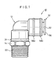
- The tube joint according to claim 1, wherein a connecting member, which is made of a metal material and which is adapted to be screwed into a port of a pressure fluid driven apparatus, is coupled to a first end of said body , and another ring member made of metal which has its outer circumference pressed radially inwardly so that said body and said connecting member are prevented from disengagement, is fitted to said outer circumferential wall surface of said body coupled to said connecting member; and
wherein said connecting member has at least one annular expanded section for preventing the disengagement of said connecting member from said body. - The tube joint according to claim 1, wherein said attachment/detachment mechanism further includes a seal member for surrounding an outer circumferential surface of said tube to prevent a pressure fluid from leakage.
- The tube joint according to claim 1, further comprising an additional ring member fitted to the outer circumferential wall surface of said second end of said body and pressing the outer circumferential wall surface of said body radially inwardly for preventing said body from being deformed, said additional ring member being positioned such that the projection of said engaging member is located between the ring member and the additional ring member.
- The tube joint according to claim 1, wherein said second end does not have any slits.
- A tube joint comprising:wherein said attachment/detachment mechanism is constructed such that said engaging member engages with said taper section of said collet to press said fastening section radially inwardly toward the outer circumferential surface of the tube when a force is applied to the tube to pull out the tube from the attachment/detachment mechanism.a body made of a resin material having a distal edge and an opening at a second end of said body;an attachment/detachment mechanism into which a tube is configured to be inserted and which comprises:a fastening section configured to bite an outer circumferential surface of the tube;a collet having a taper section provided outside said fastening section; andan engaging member provided outside said taper section, said engaging member having a projection which outwardly projects from an outer circumferential surface of said engaging member and which engages with an inner circumferential wall surface of said body at said second end;a ring member fitted to an outer circumferential wall surface of said body at said second end,
- The tube joint according to claim 8, wherein said ring member presses the outer circumferential wall surface of said body radially inwardly.
- The tube joint according to claim 8, wherein a connecting member, which is made of a metal material and which is adapted to be screwed into a port of a pressure fluid driven apparatus, is coupled to a first end of said body, and another ring member made of metal which has its outer circumference pressed radially inwardly so that said body and said connecting member are prevented from disengagement, is fitted to said outer circumferential wall surface of said body coupled to said connecting member; and
wherein said connecting member has at least one annular expanded section for preventing the disengagement of said connecting member from said body. - The tube joint according to claim 8, wherein said attachment/detachment mechanism further includes a seal member for surrounding an outer circumferential surface of said tube to prevent a pressure fluid from leakage, and a release bush inserted into a chuck to release a fastened state of said fastening section with respect to said tube.
- The tube joint according to claim 8, further comprising an additional ring member fitted to the outer circumferential wall surface of said second end of said body and pressing the outer circumferential wall surface of said body radially inwardly for preventing said body from being deformed, said additional ring member being positioned such that the projection of said engaging member is located between the ring member and the additional ring member.
- The tube joint according to claim 8, wherein said second end does not have any slits.
- A tube joint comprising:wherein said attachment/detachment mechanism is constructed such that said engaging member engages with said taper section of said collet to press said fastening section radially inwardly toward the outer circumferential surface of the tube when a force is applied to the tube to pull out the tube from the attachment/detachment mechanism; anda body made of a resin material having a distal edge and an opening at a second end of said body;an attachment/detachment mechanism into which a tube is configured to be inserted and which comprises:a fastening section configured to bite an outer circumferential surface of the tube;a collet having a taper section provided outside said fastening section; and an engaging member provided outside said taper section, said engaging member having a projection which outwardly projects from an outer circumferential surface of said engaging member and which engages with an inner circumferential wall surface of said body at said second end;a ring member fitted to an outer circumferential wall surface of said body at said second end and pressing the outer circumferential wall surface of said body radially inwardly,
wherein said ring member presses the outer circumferential wall surface of said body radially inwardly, and said taper section of said collet engages with an end surface of said engaging member to press said fastening section for preventing said engaging member from being disengaged from said body . - The tube joint according to claim 14, wherein a connecting member, which is made of a metal material and which is adapted to be screwed into a port of a pressure fluid driven apparatus, is coupled to a first end of said body, and another ring member made of metal which has its outer circumference pressed radially inwardly so that said body and said connecting member are prevented from disengagement, is fitted to said outer circumferential wall surface of said body coupled to said connecting member; and
wherein said connecting member has at least one annular expanded section for preventing the disengagement of said connecting member from said body. - The tube joint according to claim 14, wherein said attachment/detachment mechanism further includes a seal member for surrounding an outer circumferential surface of said tube to prevent a pressure fluid from leakage, and a release bush inserted into a chuck to release a fastened state of said fastening section with respect to said tube.
- The tube joint according to claim 14, further comprising an additional ring member fitted to the outer circumferential wall surface of said second end of said body and pressing the outer circumferential wall surface of said body radially inwardly for preventing said body from being deformed, said additional ring member being positioned such that the projection of said engaging member is located between the ring member and the additional ring member.
- The tube joint according to claim 15, wherein said second end does not have any slits.
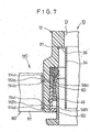
- A tube joint comprising:a body made of a resin material and having a first end side with an edge;a connecting member inserted into the first end side of the body, said connecting member having an annular expanded section which outwardly projects from an outer circumferential surface of the connecting member and which engages with an inner circumferential wall surface of said body at said first end side; anda ring member fitted to an outer circumferential wall surface of said first end side of said body and pressing the outer circumferential wall surface of said body radially inwardly, said ring member being positioned between the annular expanded section of said connecting member and the edge of said first end side, so that said body and said connecting member are prevented from disengagement.
- The tube joint according to claim 19, wherein said ring member is formed to have a substantially circular configuration by tightening its outer circumference toward its center substantially uniformly over its entire circumference.
- The tube joint according to claim 19, further comprising a seal member provided between the outer circumferential surface of the connecting member and the inner circumferential wall surface of said body at said first end side such that the annular expanded section of said connecting member is located between the seal member and the ring member.
- The tube joint according to claim 21, wherein said seal member is an O-ring.
- The tube joint according to claim 19, further comprising:an attachment/detachment mechanism which is adapted to be attached to and detached from a fluid tube, said attachment/detachment mechanism including a guide member provided inside a second end side of said body, said guide member having an annular expanded section which outwardly projects from an outer circumferential surface of the guide member and which engages with an inner circumferential wall surface of said body at said second end side; andanother ring member fitted to an outer circumferential wall surface of said second end side of said body and pressing the outer circumferential wall surface of said body radially inwardly, said another ring member being positioned between the annular expanded section of said guide member and the edge of said second end side, so that said body and said guide member are prevented from disengagement.
Priority Applications (1)
| Application Number | Priority Date | Filing Date | Title |
|---|---|---|---|
| EP06009289A EP1688197A3 (en) | 1998-05-13 | 1999-04-27 | Resin tube joint with reinforcing ring |
Applications Claiming Priority (4)
| Application Number | Priority Date | Filing Date | Title |
|---|---|---|---|
| JP13013698 | 1998-05-13 | ||
| JP10130136A JPH11325362A (en) | 1998-05-13 | 1998-05-13 | Pipe joint |
| EP02013869A EP1250970B1 (en) | 1998-05-13 | 1999-04-27 | Resin tube joint with reinforcing ring |
| EP99108222A EP0957306B1 (en) | 1998-05-13 | 1999-04-27 | Apparatus for producing a tube joint |
Related Parent Applications (3)
| Application Number | Title | Priority Date | Filing Date |
|---|---|---|---|
| EP02013869A Division EP1250970B1 (en) | 1998-05-13 | 1999-04-27 | Resin tube joint with reinforcing ring |
| EP99108222.3 Division | 1999-04-27 | ||
| EP02013869.9 Division | 2002-06-22 |
Related Child Applications (1)
| Application Number | Title | Priority Date | Filing Date |
|---|---|---|---|
| EP06009289A Division EP1688197A3 (en) | 1998-05-13 | 1999-04-27 | Resin tube joint with reinforcing ring |
Publications (3)
| Publication Number | Publication Date |
|---|---|
| EP1443252A2 true EP1443252A2 (en) | 2004-08-04 |
| EP1443252A3 EP1443252A3 (en) | 2004-08-11 |
| EP1443252B1 EP1443252B1 (en) | 2006-07-05 |
Family
ID=15026827
Family Applications (4)
| Application Number | Title | Priority Date | Filing Date |
|---|---|---|---|
| EP99108222A Expired - Lifetime EP0957306B1 (en) | 1998-05-13 | 1999-04-27 | Apparatus for producing a tube joint |
| EP04008172A Expired - Lifetime EP1443252B1 (en) | 1998-05-13 | 1999-04-27 | Tube joint |
| EP06009289A Withdrawn EP1688197A3 (en) | 1998-05-13 | 1999-04-27 | Resin tube joint with reinforcing ring |
| EP02013869A Expired - Lifetime EP1250970B1 (en) | 1998-05-13 | 1999-04-27 | Resin tube joint with reinforcing ring |
Family Applications Before (1)
| Application Number | Title | Priority Date | Filing Date |
|---|---|---|---|
| EP99108222A Expired - Lifetime EP0957306B1 (en) | 1998-05-13 | 1999-04-27 | Apparatus for producing a tube joint |
Family Applications After (2)
| Application Number | Title | Priority Date | Filing Date |
|---|---|---|---|
| EP06009289A Withdrawn EP1688197A3 (en) | 1998-05-13 | 1999-04-27 | Resin tube joint with reinforcing ring |
| EP02013869A Expired - Lifetime EP1250970B1 (en) | 1998-05-13 | 1999-04-27 | Resin tube joint with reinforcing ring |
Country Status (6)
| Country | Link |
|---|---|
| US (5) | US6578879B2 (en) |
| EP (4) | EP0957306B1 (en) |
| JP (1) | JPH11325362A (en) |
| KR (1) | KR100345914B1 (en) |
| CN (2) | CN1096591C (en) |
| DE (3) | DE69932270T2 (en) |
Families Citing this family (62)
| Publication number | Priority date | Publication date | Assignee | Title |
|---|---|---|---|---|
| JPH11325362A (en) * | 1998-05-13 | 1999-11-26 | Smc Corp | Pipe joint |
| AUPQ886200A0 (en) * | 2000-07-19 | 2000-08-10 | Betaswage Pty Ltd | Hydraulic swage press |
| KR100405380B1 (en) * | 2000-12-14 | 2003-11-20 | 주식회사 디엠티 | A conection valve |
| KR100405381B1 (en) * | 2001-01-08 | 2003-11-19 | 주식회사 디엠티 | A cartridge |
| JP3925775B2 (en) * | 2001-09-07 | 2007-06-06 | 豊田合成株式会社 | Resin tube |
| DE10206852B4 (en) * | 2002-02-18 | 2009-02-12 | Walterscheid Rohrverbindungstechnik Gmbh | Coupling for connecting hydraulic lines |
| JP3932398B2 (en) * | 2002-03-18 | 2007-06-20 | Smc株式会社 | Pipe fitting |
| JP4288314B2 (en) * | 2002-03-22 | 2009-07-01 | Smc株式会社 | Pipe fitting |
| KR20030092288A (en) * | 2002-05-29 | 2003-12-06 | 현대자동차주식회사 | a tube connecting structure |
| US20050242581A1 (en) * | 2002-06-05 | 2005-11-03 | Nowling Michael D | Coupler |
| US7506899B2 (en) * | 2003-03-20 | 2009-03-24 | Rain Bird Corporation | Multi-diameter tube fitting |
| JP4329063B2 (en) * | 2003-05-23 | 2009-09-09 | Smc株式会社 | Pipe fitting |
| WO2005003614A1 (en) * | 2003-07-04 | 2005-01-13 | Friatec Aktiengesellschaft | Plug-in coupling |
| JP2006010010A (en) * | 2004-06-29 | 2006-01-12 | Smc Corp | Pipe joint |
| SE0403154L (en) * | 2004-12-21 | 2006-03-28 | Volvo Lastvagnar Ab | Container for flowing material |
| WO2007010339A2 (en) * | 2005-07-19 | 2007-01-25 | Pi.Effe.Ci. S.R.L. | Tool for the connection of tubes by means of connection sleeves |
| FR2892474B1 (en) * | 2005-10-26 | 2007-12-28 | Legris Sa | NON-AGGRESSIVE ANCHOR WASHER |
| DE102006010316A1 (en) * | 2006-03-07 | 2007-09-13 | Karl Storz Gmbh & Co. Kg | clutch mechanism |
| DE102006015158B4 (en) * | 2006-03-30 | 2009-10-29 | Kaimer Gmbh & Co. Holding Kg | Connectors |
| US7419189B2 (en) * | 2006-04-26 | 2008-09-02 | International Engine Intellectual Property Company, Llc | Hydraulic fitting |
| US20080114308A1 (en) * | 2006-11-13 | 2008-05-15 | Di Palma Giorgio | Vascular Access Port with Catheter Connector |
| ITTO20060846A1 (en) * | 2006-11-29 | 2008-05-30 | Knorr Bremse Systeme | QUICK CONNECTION DEVICE, PARTICULARLY FOR TUBES AND THE LIKE. |
| US20080231048A1 (en) * | 2007-03-22 | 2008-09-25 | Norgren, Inc. | Pneumatic swivel elbow |
| US8480134B2 (en) | 2007-05-25 | 2013-07-09 | Quick Fitting, Inc. | Piping joint assembly system and method with sealing ring stabilizer |
| US8205915B1 (en) | 2007-05-25 | 2012-06-26 | Quick Fitting, Inc. | Piping joint assembly system and method |
| US20090026758A1 (en) * | 2007-07-24 | 2009-01-29 | Sanzone Brian D | Tube fitting with indication of fit |
| US7490865B1 (en) * | 2007-07-30 | 2009-02-17 | Tzu Liang Tsai | Quick connector |
| JP2011513152A (en) | 2008-03-04 | 2011-04-28 | エンタープライジズ インターナショナル インク | Strap changer for banding system |
| CN201262294Y (en) * | 2008-08-04 | 2009-06-24 | 浙江兴鑫爱特铜业有限公司 | Novel fast tube connecting structure |
| BRPI0804302B1 (en) * | 2008-10-07 | 2020-09-15 | Embraco Indústria De Compressores E Soluções Em Refrigeração Ltda | OIL PUMP ASSEMBLY ARRANGEMENT IN A COOLING COMPRESSOR |
| TWI387697B (en) * | 2008-10-23 | 2013-03-01 | Yugen Kaisha Hama Int | Tube fitting |
| US9857008B2 (en) * | 2008-11-20 | 2018-01-02 | Gates Corporation | Crimpable or swageable fluid power ferrules, couplings, systems and methods employing torque communication |
| WO2011004935A1 (en) * | 2009-07-08 | 2011-01-13 | (주)스톰테크 | Tube coupling |
| JP2011069395A (en) * | 2009-09-24 | 2011-04-07 | Sekisui Chem Co Ltd | Pipe joint with coming-off preventing ring, method and device of mounting the coming-off preventing ring |
| JP5709096B2 (en) * | 2009-11-18 | 2015-04-30 | Smc株式会社 | Pipe fitting |
| US8398122B2 (en) | 2010-12-30 | 2013-03-19 | Quick Fitting, Inc. | Push connect joint assembly, system and method |
| DE202012102342U1 (en) * | 2012-06-26 | 2013-10-02 | Voss Automotive Gmbh | Connecting device for pipelines |
| JP2014098472A (en) * | 2012-11-16 | 2014-05-29 | Disco Abrasive Syst Ltd | Tube connector |
| US9976677B2 (en) * | 2013-03-15 | 2018-05-22 | Ultraflo Corporation | Dual use coupling end for pipes and fittings |
| WO2015079907A1 (en) * | 2013-11-26 | 2015-06-04 | オリンパス株式会社 | Balloon removing device |
| US9377140B2 (en) * | 2014-07-08 | 2016-06-28 | Alkon Corporation | Configurable coupling apparatus for tubular elements |
| JP2016089884A (en) * | 2014-10-31 | 2016-05-23 | ニッタ株式会社 | Connecting mechanism of valve and joint in air piping |
| CN104455829B (en) * | 2014-11-30 | 2017-01-25 | 嘉兴迈思特管件制造有限公司 | Connecting pipe assembly for large automobile chassis |
| CN104455815B (en) * | 2014-11-30 | 2017-01-25 | 嘉兴迈思特管件制造有限公司 | Tapered sealing pipe connector for excavator |
| GB201502172D0 (en) * | 2015-02-10 | 2015-03-25 | Irwin William J And Canning William A | A pipe coupling |
| DE202015103455U1 (en) * | 2015-07-01 | 2015-07-14 | Ti Automotive Engineering Centre (Heidelberg) Gmbh | Connecting element for connecting a pipe end to a component of an air conditioning system |
| US9879810B2 (en) | 2015-09-18 | 2018-01-30 | Quick Fitting, Inc. | Push-to-connect joint assembly with protective shield device and method |
| US9562637B1 (en) | 2015-09-22 | 2017-02-07 | Quick Fitting, Inc. | Locking pipe joint assembly, device and method |
| US9857006B2 (en) | 2016-03-31 | 2018-01-02 | Quick Fitting, Inc. | Retaining ring for pipe joint devices |
| US9671049B1 (en) | 2016-07-27 | 2017-06-06 | Quick Fitting, Inc. | Hybrid push-to-connect fitting device and assembly |
| GB2554662A (en) * | 2016-09-30 | 2018-04-11 | Perkins Engines Co Ltd | Joint assembly |
| US9964243B1 (en) * | 2017-03-23 | 2018-05-08 | Wen Sheng Fu Co. Ltd. | Pipe joint structure |
| CN107023751A (en) * | 2017-05-15 | 2017-08-08 | 阜阳国祯燃气有限公司 | A kind of high-pressure gas storage well residual air recovery system |
| US10400929B2 (en) | 2017-09-27 | 2019-09-03 | Quick Fitting, Inc. | Fitting device, arrangement and method |
| US11560967B2 (en) * | 2018-09-04 | 2023-01-24 | Brasscraft Manufacturing Company | Rotation-resistant push-on conduit coupling cartridge |
| WO2020058818A1 (en) * | 2018-09-18 | 2020-03-26 | Tosi F.Lli S.R.L. | Quick plug-in fitting with integrated extractor device |
| US11287050B2 (en) | 2019-05-02 | 2022-03-29 | Automatic Switch Company | Solenoid valve with crimp fitting |
| CN110081252A (en) * | 2019-05-27 | 2019-08-02 | 程思哲 | A kind of flexible duct interface and the hydraulic piping that disappears |
| DE102019127857A1 (en) * | 2019-10-16 | 2021-04-22 | Voss Automotive Gmbh | Tooth lock washer |
| US10969047B1 (en) | 2020-01-29 | 2021-04-06 | Quick Fitting Holding Company, Llc | Electrical conduit fitting and assembly |
| US11035510B1 (en) | 2020-01-31 | 2021-06-15 | Quick Fitting Holding Company, Llc | Electrical conduit fitting and assembly |
| US11105452B1 (en) | 2021-02-25 | 2021-08-31 | Quick Fitting Holding Company, Llc | Push-to-connect joint assembly and device |
Citations (5)
| Publication number | Priority date | Publication date | Assignee | Title |
|---|---|---|---|---|
| US3017203A (en) * | 1957-07-19 | 1962-01-16 | W D Allen Mfg Co | Connectors for plastic hose |
| US3378282A (en) * | 1965-12-30 | 1968-04-16 | Amp Inc | Tube coupling |
| DE3831611A1 (en) * | 1988-09-17 | 1990-03-22 | Manibs Spezialarmaturen | Transition coupling between a plastic pipe and a metal pipe |
| EP0370641A1 (en) * | 1988-11-01 | 1990-05-30 | Smc Corporation | Pipe joint |
| EP0548627A1 (en) * | 1991-12-21 | 1993-06-30 | Continental Aktiengesellschaft | Method and apparatus for the sealed mounting of a piece of hose made of elastomeric material on a connecting member |
Family Cites Families (50)
| Publication number | Priority date | Publication date | Assignee | Title |
|---|---|---|---|---|
| US590258A (en) * | 1897-09-21 | Connecting hose to nipples | ||
| US602617A (en) * | 1898-04-19 | Charles h | ||
| US2139745A (en) * | 1937-04-07 | 1938-12-13 | Howard W Goodall | Hose coupling |
| US2453997A (en) * | 1946-05-02 | 1948-11-16 | Resistofiex Corp | Fitting for flexible hose |
| US3578360A (en) * | 1969-07-16 | 1971-05-11 | Perfex Plastics Inc | A fitting for a liner pipe formed of polyethylene |
| US3843169A (en) * | 1972-05-24 | 1974-10-22 | Mach & Tooling Co | Coupling for hose,pipe,tubing or the like |
| CA1025904A (en) * | 1972-08-23 | 1978-02-07 | Canadian General Electric Company Limited | Mechanically locked bell and spigot coupling for ducts |
| US4018460A (en) * | 1975-10-28 | 1977-04-19 | American Stamping Company | Hose coupling |
| US4135744A (en) * | 1976-05-13 | 1979-01-23 | Robert E. Fouts | Terminal fitting for a tubular conduit |
| US4508369A (en) * | 1978-06-02 | 1985-04-02 | Nycoil Corporation | Releasable coupling device |
| IT1195214B (en) * | 1981-10-14 | 1988-10-12 | Giovanni Fassina | QUICK JOINT FOR ELASTOMER PIPES INTENDED FOR THE TRANSPORT OF FLUIDS (GAS, LIQUIDS, POWDERS OR GRANULATES) IN PARTICULAR FOR HOUSEHOLD APPLIANCES, BOTH IN CONNECTION WITH THEM AND IN COUPLING WITH CONNECTIONS OR DIRECTLY WITH THE APPLIANCE |
| US4524501A (en) | 1982-03-31 | 1985-06-25 | United States Steel Corporation | Apparatus for joining flared ended tubes |
| JPS58155475U (en) * | 1982-04-14 | 1983-10-17 | エスエムシ−株式会社 | pipe fittings |
| FR2544407B1 (en) * | 1983-04-18 | 1986-08-08 | Legris | METHOD AND DEVICE FOR JOINING MULTIPLE ORGANS, PARTICULARLY CONNECTING ORGANS FOR FLUID FITTINGS |
| US5220716A (en) | 1983-06-17 | 1993-06-22 | Lostra John M | Tools for disassembling universal joints |
| US4593943A (en) | 1983-08-23 | 1986-06-10 | Kabushiki Kaisha Nihon Pisco | Tubing joint |
| GB8406226D0 (en) * | 1984-03-09 | 1984-04-11 | Hepworth Plastics Ltd | Pipe couplings |
| JPS614796A (en) | 1984-06-20 | 1986-01-10 | Idemitsu Kosan Co Ltd | Production of synthetic lubricating oil |
| DE3603721C2 (en) * | 1985-08-20 | 1994-11-17 | Smc Kk | Coupling for multiple passage line |
| FR2605709A1 (en) * | 1986-10-22 | 1988-04-29 | Chausson Usines Sa | Moulded connection end-piece for tubes, flexible piping and the like |
| US5054821A (en) | 1988-03-03 | 1991-10-08 | Cordis Corporation | Sterile sleeve/connector assembly |
| DE3914645A1 (en) * | 1988-05-04 | 1989-11-09 | Rasmussen Gmbh | Plug-in coupling for coupling a hose onto a pipe |
| FR2648894B2 (en) | 1989-01-04 | 1991-08-16 | Legris Sa | IMPROVEMENTS IN A CLAMP FOR INSTANTANEOUS FLUID CONDUIT CONNECTION DEVICE, AND DEVICES HAVING SUCH A CLAMP |
| US4955122A (en) | 1989-09-27 | 1990-09-11 | Nippon Air Brake Co., Ltd. | Lock unit for a fluid coupling apparatus |
| JPH073119Y2 (en) | 1989-11-20 | 1995-01-30 | シーケーディ株式会社 | Pipe fitting |
| HU215999B (en) | 1990-02-02 | 1999-04-28 | Etablissements Caillau | Pipe junction |
| US5044671A (en) * | 1990-06-21 | 1991-09-03 | S & H Fabricating And Engineering Incorporated | Swaged-type flexible hose coupling |
| US5139290A (en) * | 1990-06-25 | 1992-08-18 | Shafer Terry C | Quick coupling for plastic pipe |
| US5096231A (en) * | 1990-11-28 | 1992-03-17 | S&H Fabricating And Engineering Inc. | Flexible fluid conduit assembly |
| JPH0753032Y2 (en) * | 1991-06-11 | 1995-12-06 | 日東工器株式会社 | Pipe fitting |
| US5230539A (en) * | 1991-12-31 | 1993-07-27 | Dana Corporation | Quick connect tube coupling |
| EP0593838A1 (en) * | 1992-10-23 | 1994-04-27 | FORANTE ORAZIO & C. S.n.c. di Orazio Forante | A machine for pressing tubes, in particular the ends of rubber oleodynamic tubes for the formation of connecting pieces |
| AU5951694A (en) | 1993-02-01 | 1994-08-29 | Aeroquip Corporation | Improved hose fitting and method of making |
| US5580100A (en) * | 1994-02-25 | 1996-12-03 | Usui Kokusai Sangyo Kaisha Ltd. | Connecting joint for plastic tube |
| US5601317A (en) * | 1995-02-01 | 1997-02-11 | Signet Systems, Inc. | Clamping system |
| JP3593382B2 (en) | 1995-04-13 | 2004-11-24 | Smc株式会社 | Pipe fittings |
| US6115898A (en) | 1995-06-06 | 2000-09-12 | Btm Corporation | Force multiplying apparatus for clamping a workpiece and forming a joint therein |
| US5582439A (en) * | 1995-06-07 | 1996-12-10 | Spears Manufacturing Company | Strengthened pipe fitting and method |
| DE19521755C1 (en) | 1995-06-14 | 1996-10-02 | Schunk Fritz Gmbh | System repeatedly connecting two components |
| PL183366B1 (en) * | 1995-07-07 | 2002-06-28 | Marley Tile Ag | Press-fit pipe unions |
| FR2737276B1 (en) * | 1995-07-24 | 1997-10-17 | Manuli Automobile France Sa | SEALED CONNECTION DEVICE BETWEEN A RIGID TUBE END AND A FLEXIBLE HOSE AND METHOD FOR MANUFACTURING SUCH A DEVICE |
| JP3081864B2 (en) | 1996-01-08 | 2000-08-28 | 三井化学株式会社 | Synthetic resin pipe joint with metal connecting member and method of manufacturing the same |
| US5722702A (en) * | 1996-04-12 | 1998-03-03 | Arnco Corporation | Plastic pipe compression coupler |
| US5715723A (en) * | 1996-08-14 | 1998-02-10 | Owens; Carl H. | Hose crimping apparatus |
| JPH11325362A (en) | 1998-05-13 | 1999-11-26 | Smc Corp | Pipe joint |
| US6010162A (en) * | 1998-09-25 | 2000-01-04 | Aeroquip Corporation | Clip fitting for a hose |
| JP3372886B2 (en) * | 1999-02-18 | 2003-02-04 | エスエムシー株式会社 | Pipe fittings |
| US6155898A (en) * | 1999-04-16 | 2000-12-05 | Hollywood Hopeful Productions L.L.C. | Convertible amphibious shoes for swimming and walking |
| JP4288314B2 (en) * | 2002-03-22 | 2009-07-01 | Smc株式会社 | Pipe fitting |
| JP4110520B2 (en) * | 2002-10-23 | 2008-07-02 | Smc株式会社 | Pipe fitting |
-
1998
- 1998-05-13 JP JP10130136A patent/JPH11325362A/en active Pending
-
1999
- 1999-04-27 EP EP99108222A patent/EP0957306B1/en not_active Expired - Lifetime
- 1999-04-27 DE DE69932270T patent/DE69932270T2/en not_active Expired - Lifetime
- 1999-04-27 DE DE69905514T patent/DE69905514T2/en not_active Expired - Lifetime
- 1999-04-27 EP EP04008172A patent/EP1443252B1/en not_active Expired - Lifetime
- 1999-04-27 EP EP06009289A patent/EP1688197A3/en not_active Withdrawn
- 1999-04-27 DE DE69920059T patent/DE69920059T2/en not_active Expired - Lifetime
- 1999-04-27 EP EP02013869A patent/EP1250970B1/en not_active Expired - Lifetime
- 1999-04-28 US US09/300,447 patent/US6578879B2/en not_active Expired - Lifetime
- 1999-05-08 KR KR1019990016450A patent/KR100345914B1/en active IP Right Grant
- 1999-05-13 CN CN99106397A patent/CN1096591C/en not_active Expired - Lifetime
-
2000
- 2000-09-07 US US09/656,858 patent/US6415488B1/en not_active Expired - Lifetime
-
2002
- 2002-07-08 US US10/189,457 patent/US7210708B2/en not_active Expired - Lifetime
- 2002-10-16 CN CNB021468699A patent/CN1249372C/en not_active Expired - Lifetime
- 2002-10-24 US US10/279,098 patent/US6880864B2/en not_active Expired - Lifetime
-
2005
- 2005-01-07 US US11/030,162 patent/US7093862B2/en not_active Expired - Lifetime
Patent Citations (5)
| Publication number | Priority date | Publication date | Assignee | Title |
|---|---|---|---|---|
| US3017203A (en) * | 1957-07-19 | 1962-01-16 | W D Allen Mfg Co | Connectors for plastic hose |
| US3378282A (en) * | 1965-12-30 | 1968-04-16 | Amp Inc | Tube coupling |
| DE3831611A1 (en) * | 1988-09-17 | 1990-03-22 | Manibs Spezialarmaturen | Transition coupling between a plastic pipe and a metal pipe |
| EP0370641A1 (en) * | 1988-11-01 | 1990-05-30 | Smc Corporation | Pipe joint |
| EP0548627A1 (en) * | 1991-12-21 | 1993-06-30 | Continental Aktiengesellschaft | Method and apparatus for the sealed mounting of a piece of hose made of elastomeric material on a connecting member |
Also Published As
| Publication number | Publication date |
|---|---|
| EP0957306B1 (en) | 2003-02-26 |
| EP1688197A3 (en) | 2006-08-23 |
| DE69920059D1 (en) | 2004-10-14 |
| US20010045748A1 (en) | 2001-11-29 |
| US20030067165A1 (en) | 2003-04-10 |
| EP1443252B1 (en) | 2006-07-05 |
| EP0957306A3 (en) | 2000-07-19 |
| EP1250970A2 (en) | 2002-10-23 |
| US6415488B1 (en) | 2002-07-09 |
| US20050121910A1 (en) | 2005-06-09 |
| EP1250970A3 (en) | 2002-10-30 |
| DE69932270D1 (en) | 2006-08-17 |
| US7210708B2 (en) | 2007-05-01 |
| KR19990088137A (en) | 1999-12-27 |
| KR100345914B1 (en) | 2002-07-27 |
| EP1443252A3 (en) | 2004-08-11 |
| US6578879B2 (en) | 2003-06-17 |
| CN1235254A (en) | 1999-11-17 |
| EP0957306A2 (en) | 1999-11-17 |
| DE69920059T2 (en) | 2005-09-29 |
| DE69932270T2 (en) | 2007-06-28 |
| JPH11325362A (en) | 1999-11-26 |
| DE69905514T2 (en) | 2003-12-11 |
| US7093862B2 (en) | 2006-08-22 |
| EP1250970B1 (en) | 2004-09-08 |
| DE69905514D1 (en) | 2003-04-03 |
| CN1096591C (en) | 2002-12-18 |
| EP1688197A2 (en) | 2006-08-09 |
| CN1405480A (en) | 2003-03-26 |
| US6880864B2 (en) | 2005-04-19 |
| CN1249372C (en) | 2006-04-05 |
| US20020175518A1 (en) | 2002-11-28 |
Similar Documents
| Publication | Publication Date | Title |
|---|---|---|
| US7093862B2 (en) | Tube joint and apparatus for producing the same | |
| US3822074A (en) | Releasable coupling for tubular members and method for assemblying said coupling | |
| US3685860A (en) | Hose coupling | |
| US6427309B1 (en) | Method and forming element for producing a press connection between a fitting and a pipe and being inserted into the reception of the fitting | |
| EP1065425B1 (en) | Tube joint | |
| US7350831B2 (en) | End structure of water pipe | |
| JPH0680985U (en) | Pipe joint structure | |
| JPH08178157A (en) | Pipe joint | |
| JPH0596678U (en) | Pipe joint structure | |
| US6543817B1 (en) | Process for forming radially upset tube flange and tube connector assembly formed thereby | |
| KR20040045453A (en) | Connections | |
| TWI822965B (en) | Joint structure | |
| KR102013451B1 (en) | Assembly for connecting pipes | |
| JPH02286993A (en) | Hose joint | |
| KR100393349B1 (en) | Pipe having ridge on spigot and method of forming the ridge | |
| JP2000283364A (en) | Hose joint | |
| JPH04224388A (en) | Separation preventive pipe joint | |
| JPH02240494A (en) | Corrugated pipe with joint | |
| WO2023032988A1 (en) | Pressing ring, pipe joint, and method for joining pipes | |
| JP2605195B2 (en) | Pipe joint structure | |
| JP2008051342A (en) | Pipe coupling | |
| JP4159156B2 (en) | Fitting for flexible tube | |
| JP4293769B2 (en) | Brake pipe and fittings | |
| CN116490712A (en) | Pipe joint, press ring and pipe joining method | |
| JP2000304180A (en) | Hose connector |
Legal Events
| Date | Code | Title | Description |
|---|---|---|---|
| PUAI | Public reference made under article 153(3) epc to a published international application that has entered the european phase |
Free format text: ORIGINAL CODE: 0009012 |
|
| PUAL | Search report despatched |
Free format text: ORIGINAL CODE: 0009013 |
|
| AC | Divisional application: reference to earlier application |
Ref document number: 0957306 Country of ref document: EP Kind code of ref document: P Ref document number: 1250970 Country of ref document: EP Kind code of ref document: P |
|
| AK | Designated contracting states |
Kind code of ref document: A2 Designated state(s): DE FR GB |
|
| AK | Designated contracting states |
Kind code of ref document: A3 Designated state(s): DE FR GB |
|
| 17P | Request for examination filed |
Effective date: 20041120 |
|
| AKX | Designation fees paid |
Designated state(s): DE FR GB |
|
| 17Q | First examination report despatched |
Effective date: 20050502 |
|
| GRAP | Despatch of communication of intention to grant a patent |
Free format text: ORIGINAL CODE: EPIDOSNIGR1 |
|
| GRAS | Grant fee paid |
Free format text: ORIGINAL CODE: EPIDOSNIGR3 |
|
| GRAA | (expected) grant |
Free format text: ORIGINAL CODE: 0009210 |
|
| RIN1 | Information on inventor provided before grant (corrected) |
Inventor name: MUTO, MASAAKI, C/O SMC KABUSHIKI KAISHA |
|
| RAP1 | Party data changed (applicant data changed or rights of an application transferred) |
Owner name: SMC KABUSHIKI KAISHA |
|
| AC | Divisional application: reference to earlier application |
Ref document number: 0957306 Country of ref document: EP Kind code of ref document: P Ref document number: 1250970 Country of ref document: EP Kind code of ref document: P |
|
| AK | Designated contracting states |
Kind code of ref document: B1 Designated state(s): DE FR GB |
|
| REG | Reference to a national code |
Ref country code: GB Ref legal event code: FG4D |
|
| REF | Corresponds to: |
Ref document number: 69932270 Country of ref document: DE Date of ref document: 20060817 Kind code of ref document: P |
|
| ET | Fr: translation filed | ||
| PLBE | No opposition filed within time limit |
Free format text: ORIGINAL CODE: 0009261 |
|
| STAA | Information on the status of an ep patent application or granted ep patent |
Free format text: STATUS: NO OPPOSITION FILED WITHIN TIME LIMIT |
|
| 26N | No opposition filed |
Effective date: 20070410 |
|
| REG | Reference to a national code |
Ref country code: FR Ref legal event code: PLFP Year of fee payment: 18 |
|
| REG | Reference to a national code |
Ref country code: FR Ref legal event code: PLFP Year of fee payment: 19 |
|
| REG | Reference to a national code |
Ref country code: FR Ref legal event code: PLFP Year of fee payment: 20 |
|
| PGFP | Annual fee paid to national office [announced via postgrant information from national office to epo] |
Ref country code: DE Payment date: 20180420 Year of fee payment: 20 |
|
| PGFP | Annual fee paid to national office [announced via postgrant information from national office to epo] |
Ref country code: FR Payment date: 20180420 Year of fee payment: 20 |
|
| PGFP | Annual fee paid to national office [announced via postgrant information from national office to epo] |
Ref country code: GB Payment date: 20180418 Year of fee payment: 20 |
|
| REG | Reference to a national code |
Ref country code: DE Ref legal event code: R071 Ref document number: 69932270 Country of ref document: DE |
|
| REG | Reference to a national code |
Ref country code: GB Ref legal event code: PE20 Expiry date: 20190426 |
|
| PG25 | Lapsed in a contracting state [announced via postgrant information from national office to epo] |
Ref country code: GB Free format text: LAPSE BECAUSE OF EXPIRATION OF PROTECTION Effective date: 20190426 |