BACKGROUND OF THE INVENTION
1. Technical Field of the Invention
-
The present invention relates to an integrated building
production information system capable of making the work
solution of a design department and an execution department more
rational and more efficient by electronicizing key jobs
(integration, estimation, procurement, profit-and-loss
management and the like) of the production side in a field of
construction.
2. Background Art
-
Particularly, the present invention relates to a database
CAD (computer-aided design) system which can aim at making more
efficient and more laborsaving the work of preparing design
drawings and specifications and at improving the productivity
and quality by making it possible for personal computers using
CAD software connected with a database to grasp necessary
quantities and share necessary data for design among the
personal computers, by integrating specifications and
quantities in a design work using CAD's performed by each
personal computer, and by unifying the data flow from design
information to estimation and execution information.
-
Up to now, pattern information (drawing information) as
information for building production has been generally
communicated by means of "paper".
-
On the contrary, in recent years, with the advance of
information-systematization in each domain of building
production, CAD is extensively used and the present purpose of
it is to improve the efficiency of drawing figures and the
quality of drawing representation.
-
Thus, due to the above-mentioned purpose, the range of
utilization of CAD stays mostly within each domain specific to
design or execution.
-
From 1980's to the early part of 1990' s, "CAD systems for
integrating design and execution into a consistent work" were
developed by many companies including general constructors, and
features common to them are as follows.
- (1) A minicomputer or an EWS (engineering workstation) is
utilized as a base;
- (2) Attribute parameters are made separately by the respective
companies;
- (3) Jobs of picking and totalizing quantities are performed
within a single system;
- (4) Mainly the scope of utilization of the system is on and after
an execution design stage; and
- (5) The system is operated by an operator.
-
-
However, for all CAD data of drawings made with much effort,
there has not been a mechanism for utilizing them in a process
of estimating quantities or preparing execution drawings being
the next process.
-
Estimated quantities have been computed mainly by an
outside order estimation office on the basis of design drawings
(paper information) , and execution drawings have also been made
mainly by an outside order office as definitely settling pending
parts in design drawings and adding information of execution
to them.
-
On the other hand, execution design drawings and
specifications representing the contents of estimation and
contract have contained a too small amount of information and
a too large amount of pending contents to perform execution as
they are.
-
The present situation in which redo or readjustment
occurs due to defining the contents of design or specifications
as preparing execution drawings in course of construction and
the next process is performed as the execution information is
not definitely determined. Such present situation has
hindered the rationalization in various aspects.
-
In order to promote the rationalization of building
production, it is necessary to make the degree of definite
settlement as high as possible at an upstream stage, namely,
at a design stage in an early process.
-
And the maximum usefulness of electronic information
including CAD data is clearly the possibility of using the data
in various applications, and in order to improve the efficiency
of building production by making the best use of its property,
it is necessary to distribute design information generated at
an early stage of a project as converting the design information
so as to meet each stage of production.
-
Thereupon, there is a synthetic drawing preparation
system of Japanese Patent Laid-Open Publication No. Hei
8-235,243 of a Japanese patent application among matters filed
as a synthetic drawing preparation system making it possible
to uniformly handle building drawing data and equipment drawing
data prepared by heterogeneous CAD apparatuses.
-
This is a synthetic drawing preparation system which
converts drawing data among a building CAD apparatus for
preparing building drawings, an equipment CAD apparatus for
preparing equipment drawings and a synthetic CAD apparatus for
preparing synthetic drawings, said system converting drawing
data on the layer of the building CAD apparatus or equipment
CAD apparatus and drawing data on the layer of the synthetic
CAD apparatus into each other, and preparing synthetic drawings
by means of the synthetic CAD apparatus on the basis of drawings
prepared by the building CAD apparatus and the equipment CAD
apparatus.
-
According to this Japanese Patent Laid-Open Publication
No. Hei 8-235,243, drawings of the building side such as plan
detail drawings, skeleton drawings and the like to be prepared
by building CAD apparatuses are made by the respective building
CAD apparatuses.
-
Since the prepared drawings have the data formats of the
respective dedicated CAD apparatuses, they are converted into
the DXF format and converted from each unique layer of these
dedicated CAD apparatuses into the layer of the synthetic CAD
apparatus.
-
And each of drawings to be prepared by the equipment side
such as drawings of electric equipment, sanitary equipment, air
conditioning equipment and the like is made by a CAD apparatus
possessed by each subcontractor in charge of equipment.
-
Since the prepared drawings have the data formats of the
respective dedicated CAD apparatuses, they are converted into
the DXF format and converted from each unique layer of these
dedicated CAD apparatuses into the layer of the synthetic CAD
apparatus.
-
A processing synthetic CAD apparatus in a synthetic CAD
apparatus can handle uniformly drawings made by a building CAD
apparatus or an equipment CAD apparatus. In case that a
building side performs a change having an influence on the whole
execution, for example, a synthetic CAD apparatus converts the
data format and layer of a changed drawing and passes the
converted drawing data to another building CAD apparatus or
equipment CAD apparatus, which can perform a necessary change
on the basis of the changed drawing data by means of each
dedicated CAD. The changed drawing is converted in the
synthetic CAD apparatus side and is combined with a layer
according to a synthetic drawing and outputted to a display
device or a plotter.
-
In this way, since a drawing made by each dedicated CAD
apparatus can be handled by another dedicated CAD apparatus,
a modification based on some changed spot can be handled
uniformly by a building side or an equipment side and, therefore,
even a large-scale building can be corrected exactly and
quickly.
-
However, said synthetic drawing preparation system of
Japanese Patent Laid-Open Publication No. Hei 8-235,243 is a
system for securing the compatibility in a job of making a
synthetic drawing at an execution stage but is not a system for
securing the compatibility at a design stage. Securing the
compatibility at an execution stage results in having many
pending matters, and redo and readjustment occur even in the
course of execution as described above and the rationalization
is hindered in various aspects by entering the next process as
leaving necessary information not definitely determined.
-
And this system uses pattern data of a drawing but does
not inheritably use the attribute of a design drawing. The
linkage of such pattern data is low in the degree of freedom
and the CAD data of a design drawing can be utilized in making
a synthetic drawing in the next process as pattern data, but
since the attribute of it is not utilized, the data cannot be
utilized in calculation of quantities to be estimated.
-
Further, said synthetic drawing preparation system of
Japanese Patent Laid-Open Publication No. Hei 8-235,243 is a
system which fully performs a layer management of drawing data
and converts the layer of drawing data into a layer
configuration convenient for a synthetic drawing on the basis
of a predetermined rule of layer conversion, but the layer rule
is not often strictly observed and an effective result cannot
be often obtained. Generally, management based on layer is
effective for an object but is often ineffective for another
object, and in case of using a layer management for another
object, such a system performs conversion but often cannot
effectively distribute data.
-
Further, the synthetic drawing preparation system of
Japanese Patent Laid-Open Publication No. Hei 8-235,243 is
supposed as a system primarily handling two-dimensional matters
and cannot perform examination from an optional direction in
confirming the compatibility and is difficult to estimate
exactly the quantities.
-
By the way, in order to integrate building production
information, it is necessary to take the compatibility among
building information, structure information and equipment
information, but it is caused by the following reasons that CAD
systems of building, structure and equipment have not been
unified and have not come to spread. There are such reasons
as a fact that a CAD system has been expensive in lease expense
of hardware/software, maintenance cost and the like, a fact that
there has not been a receiver of data since CAD has not been
popular in building sites, a fact that estimation is often
performed by manually picking up and no electronic data have
been utilized in a downstream process, and a fact that an
operator has been required not only to operate a CAD system but
also to have deep knowledge of both design drawings and
execution drawings, namely, a young operator skilled in
operation of CAD has also needed to be skilled in settlement
or sequence of execution and the like.
-
Further, the following factors are conceivable.
-
The work of a conventional CAD system is only the exchange
of pattern data in the DWG format or DXF format and exchanges
data having no attribute from beginning to end.
-
And two-dimensional data are primarily handled and the
correction of errors caused by conversion requires much time,
and it is difficult to check the compatibility by means of
two-dimensional superposition of pattern data.
DISCLOSURE OF THE INVENTION
-
The present invention aims at solving said disadvantages
of the prior art, and a first object of the invention is to
realize improving the quality of a design drawing and provide
an integrated building production information system in which
information is unified by developing a function of linking CAD
information and high-quality data being excellent in
compatibility made at an execution design stage can be obtained
as a result that the compatibility can be spontaneously obtained
or that the efficiency of collation work can be improved.
-
A second object of the invention is to shorten the whole
process and provide an integrated building production
information system in which a work of making data compatible
can be easily advanced further in a short time, and, therefore,
the whole process is shortened and furthermore, the compatible
data can be diverted and utilized at the estimation and
execution stages after the execution design stage and the
efficiency of building production can be comprehensively
improved.
-
A first feature of the present invention in order to
achieve the above-mentioned objects provides as its main
purport an integrated building production information system
comprising a design CAD based on software of building, structure
and equipment, and a database built in the outside separately
from this design CAD, said database making an integrated DB-CAD
system of building, structure and equipment as an
execution-linked system in DB-CAD's sharing data of a standard
database, wherein said integrated building production
information system stores the information made compatible by
three-dimensional superposition at the time of design into the
shared database (DB) of the integrated DB-CAD system and further
receives and links information of this shared database to
external systems such as a skeleton drawing CAD, reinforcing
bar and steel frame systems and the like and makes execution
information.
-
Describing in more detail, according to the present
invention, design CAD's are based on different software
products according to the respective features of building,
structure and equipment (building: Graphisoft, structure:
AutoCAD, and equipment: CADWe'll CAPE) and databases share MDB
data of Microsoft Access being a standard database of Kajima,
and since a database made of CAD data is not shared but a database
disconnected separately from CAD is made in the outside and
shared in such a way, it is enough to develop only an interface
part for connecting a CAD software product with a database and
exchanging information between them.
-
Further, it is enough to use only de facto standard
articles available anywhere on the market as a CAD software
product and a database software product, said articles being
easy to use and arrange.
-
In addition to this, an execution-linked system (for
estimating quantities and making execution drawings), which can
be integrated with a DB-CAD (database CAD), receives
information of a shared database, diverts design data to the
execution-linked system and thereby links these data to a
skeleton drawing CAD or reinforcing bar and steel frame systems,
and performs consistently operations to the estimation of
quantities and the preparation of execution drawings, and
thereby makes it possible to improve the efficiency of work and
reduce the expense of estimation/preparation of execution
drawings.
-
And information of the shared database is excellent in
compatibility due to integrated utilization of DB-CAD's of
building, structure and equipment systems, and can be made
higher in degree of definite settlement by making execution
design drawings, and makes it possible to take information of
an execution side into design at an early stage and improve the
compatibility and linkage between design drawings and execution
drawings.
-
As for execution, a branch office or the like can manage
for itself the quantities to be the core of a building by
utilizing the estimated quantities; and by incorporating
information of the execution side into design at an early stage
and performing a high-compatibility design being high in degree
of definite settlement, it is possible to reduce redoing jobs
caused by design and site works spent for improving the degree
of definite settlement of design.
-
And since a synthetic drawing efficiently made due to data
linkage has an execution settlement added and clearly indicates
a part which must be decided by a building site side at an
execution stage, the building site side can check mutually
various production drawings on the basis of this synthetic
drawing and this leads to a smooth construction management.
-
Since a skeleton drawing can also be automatically made
on the basis of said synthetic drawing, the reliability of it
is high. As for equipment, data is utilized as an equipment
execution original drawing, which is diverted to an equipment
execution drawing by a cooperative company and can be utilized
in a job in which execution has been started.
-
By the way, according to a system of the present invention,
the sorting by attribute is effective without depending on layer.
In case that the contents described in a DB are linked to a CAD
of an execution system, since the linked contents are reproduced
by a CAD software function at the linked side, there is the merit
that work can be performed in a layer configuration convenient
for the linked side regardless of the layer configuration at
the original CAD software side. The original CAD software side
can also do with a layer configuration convenient to itself and
does not need to consider the layer configuration of the linked
side. The linkage through DB has a merit that it can be
performed regardless of layer configuration.
-
In addition to said action, the system performs
superposition of plans by a two-dimensional CAD software
product, superposition of plan sections and elevation sections
at predetermined positions by a three-dimensional CAD software
product and further new superposition of three-dimensional
objects by a three-dimensional CAD software product, said
superposition having been used up to now as means for securing
the compatibility; and the three-dimensional superposition has
the following merits.
- (1) A three-dimensional system makes it possible to examine and
confirm the compatibility and the like from an optional
direction.
- (2) A system for accurately estimating the quantities needs
originally to be three-dimensional.
-
-
The present invention makes it possible to immediately
find incompatibility by viewing a part to be verified from an
optional direction out of 360°.
-
A conventional superposition method of plan sections and
elevation sections cut out by a three-dimensional CAD has
specified in advance the positions of sections to be superposed,
cut out these sections by CAD's of the respective systems and
then checked the superposed part.
-
However, this method takes a long time for prearrangement
and further, in case that an irrational and questionable part
appears, it is necessary to repeat the same method in order to
check a section taken along another direction and, therefore,
this method has been inefficient due to needing double labor.
-
The present invention provides and reproduces
three-dimensional information as data of DB or data in the IFC
format from building and equipment DB's to a three-dimensional
building CAD.
-
Due to this, it is possible to confirm the superposed state
of building, structure and equipment from any direction on a
three-dimensional building CAD.
-
Further, in comparison with the case of cutting out and
superposing said predetermined sections, it is possible to take
the contents of structure and equipment as three-dimensional
objects into a three-dimensional building CAD by simply reading
three-dimensional data of structure and equipment and,
therefore, the prearrangement is made remarkably labor-saving
and it is not necessary to repeatedly check.
-
Furthermore, since data with attribute of structure and
equipment is taken into a three-dimensional building CAD, it
is possible to take in only necessary information for checking
the compatibility, check interference by means of attribute and
easily check the interference of parts difficult to judge by
only viewing a display screen.
-
Thus, although building, structure and equipment CAD's
are based respectively on different CAD software products, they
are kept compatible with one another on DB's.
-
A second feature of the present invention provides as its
purport an integrated building production information system,
wherein a design CAD makes a building model virtually
reproducing a building to be actually built after now inside
a computer software product using a personal computer-based
three-dimensional CAD programmed so that a shape made on CAD
software and an attribute being its own property are linked with
each other on the CAD software, and stores building
specifications such as the specifications, dimensions,
quantities, heights and the like of a structural skeleton,
finish, fittings, equipment piping, ducts, and machines and
instruments as attribute data into the shared database.
-
According to the present invention, in addition to the
action of said first feature, differently from a conventional
two-dimensional CAD simply drawing lines, since a design CAD
makes a virtual building model (virtually reproducing a
building to be actually built from now in a piece of computer
software) by means of a personal computer-based
three-dimensional CAD having an obj ect function (programmed so
that an object drawn on a piece of CAD software behaves having
an attribute being its own property within the CAD software)
and has such attributes as the specifications, dimensions,
quantities, heights (position information) and the like of a
structural skeleton, finish, fittings, equipment piping, ducts,
and machines and instruments stored in a shared database, by
reading and reproducing the information by means of the CAD
software of the execution side it is possible to reproduce
attribute information as well as pattern information, save a
labor of repetitive input, and continue working in a layer
configuration convenient to its own CAD software.
-
The linkage of a shape made on such object-oriented CAD
software to its attribute in the CAD software means that when
the shape is changed the quantity is also changed at the same
time.
-
For example, a building has a wall and in case of providing
a window in this building, the window has the property of making
a hole in the wall. And the linkage is a sequence of changes
that when the window is changed in size the hole is also changed
in size (the wall is also changed in area).
-
In case of equipment, for example, in case of piping, the
linkage has use, piping material and size as attribute, and in
case of branching, it generates a joint having a shape adapted
to its material and size and makes it impossible to join pipes
having different uses with each other.
-
In case of structure, the linkage is as follows.
- 1. Since there is information what floor columns and walls
belong to, when the floor height information is changed all of
the columns and walls are automatically changed in height.
- 2. Since the relation of connection between members is
recognized, for example, when a column is changed in size, a
beam attached to the column is automatically changed in length
adaptively to movement of the column face.
- 3. When the shape information of a member section symbol is
changed, all members arranged with this symbol are recognized
with a new shape.
-
-
In case of two-dimensional CAD, two-dimensional plane
data are superposed and the incompatibility in height has been
judged by a person. In order to make this easy to do, there
has been performed a contrivance for making it easy to find the
incompatibility in height by performing a layer classification
by height information, giving symbols to and classifying in
advance layers such as a ceiling surface, ceiling inside, wall
surface, floor surface and the like, and performing a layer
change on the superposed drawings. In case of
three-dimensional CAD as well, in case that the respective
systems use different three-dimensional CAD's, it has been
performed that the sections to be superposed are predetermined
in position, the predetermined sections are made by the
respective three-dimensional CAD's, their data are superposed
on each other and thereby the compatibility is confirmed.
-
The present invention makes it possible to confirm the
compatibility from an optional direction in a short time by
newly superposing three-dimensional objects as they are as a
means for storing compatible information.
-
And it is possible to check the interference, utilizing
attribute information without performing a layer change.
-
Further, a system of the invention makes it possible to
reproduce attribute information as well as pattern information,
save a labor of repetitive input and continue working in a layer
configuration convenient to its own CAD software by reading and
reproducing information stored in a shared database by means
of a CAD software product of the execution side.
-
A third feature of the present invention provides an
integrated building production information system having the
following matters as its purport.
-
Databases are built in the outside separately from design
CAD's and these design CAD's are based on building, structure
and equipment software products.
-
The databases make it possible to grasp and share the
quantities by sorting data of a standard database into character
information and pattern information by means of a design CAD
on a personal computer, unify specifications and quantities and
unify data flows from design information to estimation and
execution information.
-
The invention makes an integrated DB-CAD database of
building, structure and equipment as an execution-linked system
in DB-CAD's, and links and integrates with one another the
database CAD's comprising three DB-CAD's including a building
DB-CAD related to finish, fittings and the like, an equipment
DB-CAD related to machines and instruments, piping, ducts,
wiring and the like, and a structure DB-CAD related to columns,
beams, slabs and the like.
-
Between the building DB-CAD and the equipment DB-CAD, a
means for linking and integrating these DB-CAD's with one
another provides equipment 3-D information (three-dimensional
information of equipment) from the equipment DB-CAD to the
building DB-CAD, returns 3-D interference information from the
building DB-CAD to the equipment DB-CAD, and provides plan
information (plan drawing, room area, room name, ceiling height
and floor height) and skeleton information such as building
shape information, building member information, building
section information and the like at the beginning of making
drawings,
between the structure DB-CAD and the equipment DB-CAD,
said means provides such skeleton information as building shape
information, building member information, building section
information and the like from the structure DB-CAD to the
equipment DB-CAD, and returns skeleton opening (sleeve)
information such as information of making a hole in said
skeleton information from the equipment DB-CAD to the structure
DB-CAD, and
between the building DB-CAD and the structure DB-CAD,
said means transfers reciprocally such skeleton information as
building shape information, building member information,
building section information and the like, and confirms
mutually such skeleton information.
-
A fourth feature of the present invention provides as its
purport an integrated building production information system
for realizing the linkage of data between different CAD software
products, further transferring reciprocally data described
with character information (DB information), realizing the
exchange of three-dimensional data with attribute, and making
the information reading CAD side reproduce the attribute and
pattern on the basis of this information.
-
The present invention having the third and fourth
features, intending to realize the data linkage between
different CAD software products, makes it possible to take in
information and secure the compatibility by means of a method
which performs the guarantee of compatibility and the
unification of data, makes a means of three-dimensional
superposition, and, therefore, reciprocally transfers data
described with character information (DB information) and
realizes the exchange of three-dimensional data with attribute
and makes the data reading CAD side reproduce the attribute and
pattern on the basis of the information.
-
The linkage of the building DB-CAD with the structure
DB-CAD make it possible to secure the compatibility of skeleton;
the linkage of the building DB-CAD with the equipment DB-CAD
makes it possible to confirm and secure the compatibility of
the contents of equipment with a building plan, and reproduce
a building plan at the start of drawing figures; and the linkage
of the structure DB-CAD with the equipment DB-CAD makes it
possible to reproduce the skeleton at the beginning of drawing
figures and return the skeleton opening information to the
structure DB-CAD.
BRIEF DESCRIPTION OF THE DRAWINGS
-
- Figure 1 is an explanatory diagram showing an embodiment
of an integrated building production information system of the
present invention.
- Figure 2 is an explanatory diagram showing a system
configuration for embodying an integrated building production
information system of the present invention.
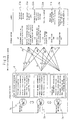
- Figure 3 is an explanatory diagram of data flow showing
an embodiment of an integrated building production information
system of the present invention.
- Figure 4 is an explanatory diagram of the confirmation
of compatibility.
- Figure 5 is an explanatory diagram showing the flow of
information of an integrated database CAD system of
building, equipment and structure.
- Figure 6 is an explanatory diagram showing output and
adjustment of the reference origins and centers.
- Figure 7 is an explanatory diagram showing output and
adjustment of the reference origins and centers in case that
the centers are separate.
- Figure 8 is an explanatory diagram showing output and
adjustment of the reference origins and centers in case that
the relation between this side model and the other side model
is not one-to-one.
- Figure 9 is an explanatory diagram showing output and
adjustment of the reference origins and centers in case that
the centers each are in the shape of a circular arc.
-
BEST MODE FOR CARRYING OUT THE INVENTION
-
An embodiment of the present invention is described in
detail with reference to the drawings in the following. Figure
1 is an explanatory diagram showing an embodiment of an
integrated building production information system of the
present invention, and numbers 1, 2 and 3 in this figure are
respectively a building CAD, a structure CAD and an equipment
CAD as design CAD's, and are based on different software
products according to their respective features.
-
There are provided databases DB-CAD (building) 1a, DB-CAD
(structure) 2a and DB-CAD (equipment) 3a built in the outside
separately from these design CAD's including building CAD 1,
structure CAD 2 and equipment CAD 3.
-
Taking building CAD 1 and DB-CAD (building) 1a as an
example, the exchange of data between a CAD and an external DB
is ordinarily performed as text data obtained by being converted
into the CSV (comma separated value) format, and an interface
making it possible to directly write/read from building CAD 1
to a specific DB-CAD (building) 1a utilizing the Access Link
function of specific software is used.
-
In this way, it is intended to directly link with each
other the design work extending from planning to basic execution
and the estimation, ordering and execution drawing preparation
jobs in associated systems utilizing attribute functions of
DB-CAD (building) 1a on a personal computer. That is to say,
data of openings, finish and the like stored in a specific DB-CAD
(building) 1a can be not only outputted to various rough
estimation systems in a design department or a fittings table
and a finish table but also utilized in various systems in an
estimation or execution department at the lower stream side.
-
By taking out a part having an RC attribute from a design
model, the design model can be utilized as a skeleton drawing
preparation model, but the effect of attributes possessed by
an object in this DB-CAD (building) 1a is in that building
elements such as columns, beams, openings and the like are
collected and various attributes such as areas, specifications
and the like are stored in a specific DB due to a fact that
building CAD 1 is linked with the specific DB. Therefore, when
a model corresponding to each stage of design has been made,
at the same time it is possible to grasp a floor area, finished
areas of a wall, ceiling and the like, and the quantity of parts
and further rough estimation and the like. A designer can
advance a rational design meeting the requirements of a customer
as considering these data. On the other hand, an estimation
department can effectively utilize these numerical data. It
is possible not only to directly input these data into an
estimation system but also to utilize them in checking data from
an estimation office.
-
As for DB-CAD (structure) 2a, when a drawing is made by
structure CAD 2, its drawing information is automatically
stored as character data into a DB through a building model,
and contrarily when data of the DB is changed, the change is
automatically reflected in an associated drawing.
-
General information of a building, information about
materials and member section information out of structural
design information of input data contents into DB-CAD
(structure) 2a are stored as an ACCESS file at the time of input.
On the other hand, information about the shape of a building
and the arrangement of members is kept as a three-dimensional
model of CAD at the time of an input operation. By keeping the
information of arrangement inside a CAD at the time of an input
operation, it is possible to realize the compatibility by
sharing information between a framing plan and a framing
elevation with response at a practical level.
-
On the other hand, a database in which information about
the shape of a building and information about the arrangement
of members are stored as a three-dimensional model of CAD at
the time of input and structure CAD 2 which outputs the
information stored as said three-dimensional model of CAD to
a file of said specific format through batch processing at the
time of linking with an external system are provided and the
whole structure design information is standardized into a fixed
form.
-
According to this DB-CAD (structure) 2a, a structure
design department can unify structure design information and
pursue the improvement in efficiency of design work by utilizing
a skeleton database CAD having files of a specific format of
this system being a three-dimensional CAD. And at a design
stage, the result of planning is automatically inputted into
a skeleton database and thereby, original data for a structure
computation can be generated. Since the compatibility between
various drawings of structural design and structural
computation can automatically be obtained through a
three-dimensional model of CAD and a skeleton database, the
efficiency of design work can be improved.
-
As output drawings, there are a framing plan, framing
elevation (automatically made) and a detailed reinforcing bar
drawing (automatically made), and additionally, there are a
detailed steel frame drawing (automatically made), a section
list (semi-automatically made) and a skeleton DB output, and
further there is also prepared a layout function for making
various mixed drawings.
-
And DB-CAD (equipment) 3a is composed of equipment CAD
3 for preparing equipment drawings and a DB combined with each
other, inputs and stores specifications of machines and
instruments by means of equipment CAD 3, associates drawing
information of a design drawing with machine and instrument
information of a specific DB, outputs one or plural pieces of
arrangement information of machines and instruments, quantity
information of materials and equipment opening information from
a design drawing into its own DB, and takes out one or plural
pieces of data for drawings, specifications, estimation and
execution.
-
Further, the system passes the information of
specifications, arrangement and quantities of machines and
instruments and the quantity information of materials as
character-based information to an adjustment and estimation
system, and diverts a design drawing as pattern (drawing)
information to an execution drawing or a completed building
drawing.
-
And DB-CAD (equipment) 3a has a job registering function,
a machine and instrument specifications registering and editing
function and a various output data preparing function, and
equipment CAD 3 has a function of referring machine and
instrument specifications information registered at its own DB,
a function of linking machines and instruments registered at
its own DB with symbols, a function of outputting arrangement
information of machines and instruments to its own DB, a
function of outputting equipment opening information into its
own DB, a function of outputting the quantities of materials,
and a function of adding attributes necessary for outputting
the quantities.
-
An integrated DB-CAD obtained by integrating these means
stores compatible information into the shared database 4, and
further an execution system 5 available on the market receives
information of this shared database 4, links the received
information to a skeleton drawing CAD or a reinforcing bar and
steel frame system on the market for a bill of quantities 6,
a synthetic drawing and skeleton drawing 7, a reinforcement
quantity execution drawing 8, a steel frame quantity execution
drawing 9 and the like.
-
The shared database 4 has three CAD's including building
CAD 1 related to finish, fittings and the like, structure CAD
2 related to columns, beams, slabs and the like, and equipment
CAD 3 related to machines and instruments, piping, ducts, wiring
and the like, and links and integrates these CAD's with one
another.
-
The present invention links with one another three
DB-CAD's including DB-CAD (building) 1a related to finish and
fittings, DB-CAD (equipment) 3a related to machines and
instruments, piping, ducts, wiring and the like, and DB-CAD
(structure) 2a related to columns, beams and slabs, as described
above.
-
As shown in Figure 5, between DB-CAD (building) 1a and
DB-CAD (equipment) 3a, this mutual linkage provides equipment
3-D information (three-dimensional information of equipment)
from DB-CAD (equipment) 3a to DB-CAD (building) 1a and returns
3-D interference information from DB-CAD (building) 1a to
DB-CAD (equipment) 3a, and provides plan information (plan,
room area, room name, ceiling height and floor height) and
skeleton information such as building shape information,
building member information, building section information and
the like at the beginning of making drawings.
-
Between DB-CAD (structure) 2a and DB-CAD (equipment) 3a,
this mutual linkage provides skeleton information such as
building shape information, building member information,
building section information and the like from DB-CAD
(structure) 2a to DB-CAD (equipment) 3a and returns skeleton
opening (sleeve) information such as information of making a
hole in said skeleton information from DB-CAD (equipment) 3a
to DB-CAD (structure) 2a, and
between DB-CAD (building) 1a and DB-CAD (structure) 2a,
this mutual linkage exchanges skeleton information such as
building shape information, building member information,
building section information and the like, and makes them
mutually confirm this skeleton information.
-
In such linkage, how to handle attribute data is the key.
For example, in a column configuration, a set of 4 segments seen
by human eyes can be recognized as a column function, but is
considered simply as a set of lines or a tetragon on CAD. The
present invention makes it possible to identify the kind,
material, size and the like of a column by providing it with
attributes as CAD.
-
How to read individual objects from a database is
performed with center information as the center. The
compatibility is secured by reading in such a way, and then the
structure side is limited to columns, beams, slabs and the like
which it is in charge of, and the equipment side is limited to
the range of responsibility of it including electric equipment,
sanitary equipment and air conditioning equipment. In
relation to matters other than these, individual objects are
transferred to and from the building side.
-
As described above, it is necessary to realize the
exchange of three-dimensional data with attributes through
transferring data described with character information (DB
information) and make the reading CAD side reproduce the
attributes and patterns on the basis of this information.
-
In order to do so, it is necessary to make objects coincide
with one another in positional relation, and for this purpose,
the reference origin and center are outputted and adjusted.
Each system outputs all information of center (symbols, and the
coordinates of the starting point and end point). It outputs
the center information for each drawing.
-
The reading side determines definitely the position of
center and vector of the opposite party from the points of
intersection of three centers of the opposite party (two
parallel lines and one line crossing them, for example, X1, X2,
Y1), and adjusts and arranges members comparing them with its
own center. This correspondence is applied, for example, in
case that a building side and a structure side respectively make
models in a one-to-one correspondence.
-
As shown in Figure 6, on the assumption that the centers
for describing a building such as X1, X2, X3, X4, X5, Y1, Y2
and Y3 exist on actual data, the system writes out these data,
determines the starting point in positional relation, for
example, takes out optional three lines of X1, X2 and Y1 and
identifies the coordinates of the points of intersection,
compares the coordinates of the points of intersection with the
data actually written there in a program, finds the relative
positions existing on the opposite party's database and makes
them correspond to X1, X2 and Y1 in its own system, and computes
and outputs the relative positions of these points as the result
of computation on the program.
-
Even in case that the centers are separated as shown in
Figure 7, since they are one in data, if optional three lines
are taken out, there is no problem, and even in case that the
relation between its own model and the opposite party's model
is not one-to-one as shown in Figure 8, there is no problem if
optional three lines can be taken out from each of the models.
Further, even in case of the center of a circular-arc shape as
shown in Figure 9, the relative positions can be identified if
the center position and radius are identified.
-
First, the linkage between DB-CAD (building) 1a and
DB-CAD (equipment) 3a is described.
-
As shown in Figure 5 described above, for checking the
interference between building and equipment the system provides
equipment 3-D information (three-dimensional information of
equipment) from DB-CAD (equipment) 3a to DB-CAD (building) 1a
and contrarily returns 3-D interference information from DB-CAD
(building) 1a to DB-CAD (equipment) 3a.
-
Having the interference information returned, said
interference information indicating what part and what part
interfere with each other in case that the building side reviews
objects described in such a form that equipment is reproduced
in the DB-CAD (building) 1a side from DB-CAD (equipment) 3a
through a database, the equipment side corrects again the
defective part.
-
Concretely, as the linkage of equipment 3-D information
to building (DB-CAD (equipment) 3a → DB-CAD (building) 1a), from
a synthetic drawing made by DB-CAD (equipment) 3a, the system
writes out information including the sizes, coordinates, file
names, file paths, figure numbers (ID) and the like of lighting
fittings, air conditioning instruments, sanitary instruments,
piping and ducts to an equipment 3-D database (EPM-DAT.mdb).
-
DB-CAD (building) 1a takes these data into DB-CAD
(building) 1a and generates data of three-dimensional equipment
members. Due to this it is possible to effectively confirm the
state of installation of equipment members or check the
interference of them with building members on DB-CAD (building)
1a.
-
A method of making said equipment 3-D data by means of
a personal computer is performed in the following manner, for
example.
- (1) A user makes a synthetic drawing by superposing the
respective drawings of electric equipment, sanitary equipment
and air conditioning equipment on one another (the synthetic
adjustment in equipment has been finished at this point of
time).
- (2) The user presses the equipment 3-D data making button.
- (3) Since a dialog screen appears, the user determines a
destination folder by pressing the reference button on the
dialog screen.
- (4) Next, the user inputs an output file name.
- (5) The user inputs a floor name for data to be outputted.
- (6) When the preparation has been completed, the user presses
the OK button.
-
-
Then, equipment 3-D data is made at a specified location.
This data is linked with DB-CAD (building) 1a.
-
Next, describing the linkage of interference information
with equipment (DB-CAD (building) 1a → DB-CAD (equipment) 3a),
DB-CAD (building) 1a makes it possible to check the interference
of equipment members taken in through the 3-D linkage with
building members such as columns, beams, walls, ceilings and
the like for each region. Further, the system outputs
information including the figure numbers (ID), file names, file
paths and the like of the equipment members extracted by this
interference checking in the form of a text file from DB-CAD
(building) 1a to the outside.
-
For example, it is assumed that there is a screen for
receiving MDB of DB-CAD (equipment) 3a of a region where the
interference with an equipment member is to be checked as a
screen for taking equipment members into DB-CAD (building) 1a.
-
The user selects "Link/Link with piping ducts/Read
equipment DB" of the menu bar and then reads MDB received from
a person in charge of equipment design, confirms "Drawing name"
and "Floor", and selects "Objective member" to be read.
-
As a result, a member of DB-CAD (equipment) 3a is arranged
on the basis of an optional intersecting point of a center.
-
A layer screen for taking in an equipment member (electric
equipment: CHCK-E, sanitary equipment: CHCK-P, air
conditioning equipment: CHCK-M) becomes a screen for indicating
the interference checking between an equipment member and a
building member, and the user selects "Link/Piping
ducts/Interference check" of the menu bar, selects "Building
member to be checked" and "Equipment member to be checked", and
presses "Interference check". Thus, "Members" and "ID's" of
a building member and an equipment member interfering with each
other are displayed on "Interference ID" of the screen.
-
And since an equipment member interfering with a building
member on a plan is displayed in red on the screen, when the
interfering member is selected on the interference check screen
the selected member is also selected on the plan.
-
On the other hand, describing from the equipment side,
it is possible to read interference information also into DB-CAD
(equipment) 3a and easily confirm what equipment member of what
drawing interferes with a building member.
-
Describing the outline of a method of taking in 3-D
interference data, the method (1) executes an interference data
input command reads interference information outputted from
DB-CAD (building) 1a and then (2) displays an interference
information confirmation screen, and (3) displays the total
number of interfering members on each floor in the interference
information confirmation screen. (4) An operator selects a
floor to be confirmed and presses a confirm button. (5) When
the confirm button is executed, drawing data to be confirmed
is automatically opened and an interfering member is displayed
in a different color. By the above-described operations, an
equipment member interfering with a building member can easily
be identified by the DB-CAD (equipment) 3a side.
-
And plan information including a plan, room area, room
name, ceiling height, floor height, skeleton information and
the like at the start of making drawings is provided from DB-CAD
(building) 1a to DB-CAD (equipment) 3a, and the DB-CAD
(equipment) 3a side can make drawings on the basis of this
information.
-
Such a linkage of building information to equipment
(DB-CAD (building) 1a → DB-CAD (equipment) 3a) makes it possible
to cut out plan data (DWG data) of each floor from
three-dimensional modeling data made by DB-CAD (building) 1a
and put the cut-out data into DB-CAD (equipment) 3a.
-
An example of a method of taking in plan data is described
below.
- (1) An operator selects DWG data by clicking an icon for opening
a file. In this case, the operator selects DWG drawing (*.dwg)
as the kind of a file. When a DWG drawing to be edited is
selected, a DWG import screen is displayed, where the operator
selects first a conversion table.
After selecting the conversion table, the operator
confirms that "Arranged layer" is set at "Building" and then
adapts "Paper size" to "Scale", and if the operator clicks "OK"
at the time of finishing the setting, a building drawing is
opened. Thus, data conversion including integration of layers,
unification of line colors and the like is performed so as to
make a building drawing for equipment easy to process.DB-CAD (equipment) 3a is provided with a conversion table
for efficiently reading DXF data and CAD We'll data as standard
in addition to a DWG import table.Next, a sheet movement is performed so as to make it
possible for DB-CAD (equipment) 3a to recognize room names and
room areas taken in from DB-CAD (building) 1a.
- (2) The operator selects a layer number and presses "OK".
- (3) The operator selects "Setting" - "Sheet function" - "Move
and copy" or selects "Move and copy" from a menu displayed by
right-clicking on a sheet tab.
- (4) Since a dialog screen is displayed, the operator selects
mode "Move (M)" and destination "Room area", and presses "OK".
- (5) Since "Enter a point you specify" (Enter: the same position)
is displayed, the operator presses "Enter" as prompted. Thus,
information of a room name and a room area which have been on
a base sheet is moved onto a room area sheet.
- (6) In a similar manner, a room name being on the room area sheet
is moved to a room name sheet. When the operator selects
"Setting" - "Sheet function" - "Move and copy" after selecting
a character to be moved, the dialog screen described above is
displayed, and the operator selects mode "Move (M)" and
destination "Room name" and presses "OK". Thus, information
of a room name that has been on the room area sheet is moved
onto the room name sheet.
- (7) Since areas are needed in case that they are used as DB-CAD
(equipment) 3a but they do not need to be printed when being
outputted, all of them are made into auxiliary figures. The
operator selects all sheet tags as keeping the Shift key
pressed.
- (8) Non-display of a dialog is selected by right-clicking the
mouse in a state where a sheet tag is displayed reverse-video
in black.
- (9) Since only a selected sheet can be edited, only a room area
is displayed by clicking a tag of the room area sheet.
- (10) The operator selects "Setting" - "Color, line" - "Change"
in the menu. Since "Select a figure" is displayed, the operator
encloses and selects all figures with the mouse and then presses
"Enter" on the keyboard.
- (11) Since an attribute change dialog is displayed, the operator
selects an auxiliary figure line from a list of line kinds and
presses "OK". The room area is made into an auxiliary figure
by the above operations.
-
-
Taking in building information with IFC data is performed
by outputting skeleton information including room areas, room
names, ceiling heights, floor heights, columns, beams, slabs,
walls and the like made by DB-CAD (building) 1a as IFC data and
reading these data into DB-CAD (equipment) 3a.
-
IFC (Industry Foundation Classes), which presents the
definition of specifications of a systematic representation
method and the data structure of a project model for handling
objects (elements such as doors, windows, walls and the like
for example) to form a building among different systems, is a
world-standard data structure.
-
Thanks to this, it is possible to collectively take data
of ceiling, floor, room area and room name in addition to data
of column, beam, slab and wall linked with a structure DB-CAD
up to now into DB-CAD (equipment) 3a from DB-CAD (building) 1a.
As shown in Figure 5, the linkage between DB-CAD (structure)
2a and DB-CAD (equipment) 3a provides skeleton information
through a structure DB converter 26 from DB-CAD (structure) 2a
to DB-CAD (equipment) 3a, and generates a three-dimensional
structural skeleton drawing in a CAD for preparing equipment
drawings of DB-CAD (equipment) 3a. The structure DB converter
26 plays a role of generating a structural skeleton on an
equipment CAD.
-
Concretely describing, in case of the linkage of
structure data to equipment data (DB-CAD (structure) 2a → DB-CAD
(equipment) 3a), data of column, beam, slab and wall made by
DB-CAD (structure) 2a can be taken into DB-CAD (equipment) 3a
by being converted by the structure DB converter 26.
-
An operation of conversion of the
structure DB converter
26 is described.
- (1) An operator starts a "skeleton converter" and specifies a
drive, directory and object on a taken object specifying screen.
- (2) The operator selects a model to be an object and presses
the OK button.
- (3) Next, the operator specifies necessary floor data.
- (4) The operator specifies a drawing number in a drawing name
specifying dialog.
- (6) The operator confirms the specified information.
Subsequently to "Conversion - drawing number - name", the
operator specifies a drawing and presses the OK button when the
specification is finished.
- (7) A dialog of being under preparation of an intermediate file
is displayed. When the conversion is ended, an information
setting dialog is displayed. The operator enters a person in
charge in the dialog and specifies a location where a converted
file is to be stored to an output device. Further, the operator
gives an object code. The operator confirms the paper size and
scale through a structure designer in advance, and specifies
them. The operator places a check on the file selection in an
attribute conversion table, and selects "For DB-CAD" as the
file.
- (8) "Conversion completed" is displayed.
- (9) Since the process is returned to the initial screen, in case
of ending the process the operator selects "File" - "End".
- (10) The operator starts Explorer. The converted data is
generated under D:¥Drawfile¥Itoen¥. (Extension.dwx)
-
-
Describing how to take in structure data, structure data
converted by the
structure DB converter 26 is read by DB-CAD
(equipment) 3a.
- (1) An operator selects DWX data by clicking an icon for opening
a file. In this case the operator selects a DWX drawing (*.dwx)
as the kind of a file.
- (2) When a DWX drawing to be edited is selected, a Cadwell import
screen is displayed. Hereupon, the operator selects first a
conversion table. The operator selects a table name
WELTABLE.wet. After selecting the conversion table, the
operator confirms that "Arranged layer" is set at "Building",
and then adapts "Paper size" to "Scale". When the setting is
finished, a structure drawing is opened by clicking "OK".
-
-
By the above-mentioned operations, a work for taking data
made by DB-CAD (structure) 2a into DB-CAD (equipment) 3a is
completed. These data are superposed on a building drawing on
the basis of a reference point. Since structure data are not
needed at the time of paper-outputting, all of them are made
into auxiliary figures.
-
On the other hand, the operator returns sleeve or
equipment opening information such as information of making a
hole in said skeleton information from DB-CAD (equipment) 3a
to DB-CAD (structure) 2a.
-
When the operator writes a drawing of equipment into a
drawing of said three-dimensional structural skeleton, the
operator returns opening information (sleeve information) of
piping or a duct in a beam, floor and wall to DB-CAD (structure)
2a and examines some reinforcement of the opening.
-
In another manner, the operator writes a sleeve into a
steel frame section called a framing elevation being in DB-CAD
(structure) 2a. The operator makes the equipment side read
again the information of sleeve and opening outputted from
DB-CAD (equipment) 3a and writes a beam sleeve into its framing
elevation and thereby can perform checking.
-
More concretely describing the linkage of such sleeve or
equipment opening information to structure (DB-CAD (equipment)
3a → DB-CAD (structure) 2a), a procedure of preparing sleeve
or equipment opening information comprises the steps of 1)
preparing a building drawing for drawing a sleeve or equipment
opening figure; 2) arranging sleeves or equipment openings
(preparing a synthetic sleeve drawing of electric, sanitary and
air conditioning equipment); 3) setting drawing information
(setting a drawing path, a sleeve path and the like); 4) adding
information of sleeve division (equipment division and class);
and 5) outputting sleeve or equipment opening information
(making SL-DAT.mdb).
-
A drawing information setting method comprises the steps
of (1) starting a job by setting air-conditioning equipment or
sanitary equipment in menu "Setting" - "Equipment change", (2)
opening a sleeve or equipment opening information output
drawing file by means of menu "File" - "Open" or icon "Open",
(3) displaying dialog "Equipment DB-CAD drawing information"
using icon "Drawing information setting", (4) specifying
necessary items including "Equipment DB path", "Structure DB
path", the kind of drawing and the like, where the kind of drawing
is a sleeve drawing, and (5) pressing button "Refer to structure
DB", referring a structure DB and making it possible to confirm
a floor order in order to specify "Floor" and "Floor order".
-
Describing a sleeve or equipment opening data preparing
method, this method comprises the steps of (1) displaying dialog
"Member insertion" by means of menu "Air conditioning" -
"Member" - "Insert" or icon "Equipment and member insertion";
(2) selecting tag "Sleeve", entering necessary items including
a member to be inserted, class 1 or 2 facing and the like and
pressing the "OK" button; (3) specifying the position of
insertion since "Specify the position of insertion (straight
pipe)" is displayed in a command input bar; (4) specifying the
end point since "Specify the end point (straight pipe)" is
displayed in the command input bar; (5) determining the
direction and pressing "Enter" since "Determine the direction
(Enter: end of selection and Shift + left click: change)" is
displayed, where thus a sleeve is inserted; (6) next, pressing
icon "Addition of sleeve division"; (7) selecting a sleeve and
then pressing "Enter" since "Select a sleeve to have division
added" is displayed, where an ID number is automatically
assigned to the sleeve; (8) checking the equipment division and
class of the selected sleeve since dialog "Equipment DB-CAD
sleeve division" is displayed, where the sleeve having an
equipment division specified has the equipment division and
class displayed by auxiliary graphic characters as shown byM (S)
at the right bottom; and
(9) invocating a check command and specifying "Sleeve check"
of the fourth item in case of attempting to check the addition
of sleeve information, where a sleeve having no sleeve division
information added after executing the command is displayed in
red, and all checked members have the information added; and
(10) saving a drawing after making the drawing has been finished
completely, where simultaneously with saving the drawing, the
sleeve or equipment opening information is written into a
database (SL-DAT.mdb) being on the equipment DB path specifying
the sleeve information.
-
Describing a sleeve or equipment opening data outputting
method, this method comprises the steps of (1) activating a
machine and instrument DB, selecting "Sleeve or equipment
opening output" from a menu for editing an objective work and
displaying dialog "Sleeve or equipment opening output"; (2)
specifying a location where data is to be saved and pressing
the "Execution" button since a dialog is displayed; (3) pressing
the "Yes" button, if satisfied, since a confirmation message
is displayed; (4) pressing the "OK" button since an end message
is displayed, where the edit menu screen comes back and the
output job is ended. This method lets a skeleton drawing
preparation CAD or a steel frame CAD read a database file
(SL-DAT.mdb) made by the above-mentioned job and automatically
generates sleeve or equipment opening information.
-
An operation of making a framing elevation is performed by
analyzing a sleeve or equipment opening database (SL-DAT.mdb)
made by DB-CAD (equipment) 3a and automatically superposing
sleeve data on the framing elevation.
-
A framing elevation making method is composed in the
following manner. (1) The method opens a framing elevation made
by DB-CAD (structure) 2a. A structure DB has a systematized
folder configuration for storing various data. Data of a
framing elevation are stored as DWG data in a FRAME folder under
a MODEL folder. (2) The content of LAYFRM*.dwg is described
in Drawing.mdb in an MDB folder. (3) A certain dialog is opened
by double-clicking Drawing. mdb. The method opens PlanFrameTbl
in this. (4) The operator can confirm the relation between DWG
file name (FrameNo) of a drawing and the drawing name (what
number of framing elevations?) by means of this table. All the
DWG file names in this table are described by names of
three-dimensional data. A drawing is selected by substituting
these data names for two-dimensional data names. For example,
in a drawing of the lower figure, a D-center framing elevation
is described as FRAME7.dwg but in this case, data opened by
equipment is LAYFRM*.dwg. (FRAME.DWG and LAYFRM*.dwg
correspond to each other on a one-to-one base. (5) When the
content can be confirmed, the framing elevation of a structure
to be an object is opened. (6) A framing elevation making
command is executed.
-
(7) A sleeve DB path and a structure DB path are specified.
i) The sleeve DB path specifies a folder set in a drawing
information setting screen of a sleeve drawing. ii) The
structure DB path specifies an MDB folder of a structure DB
converted for a sleeve drawing. The operator specifies a folder
by pressing a reference button and, if the setting is performed,
presses "OK".
-
(8) The sleeve data of each floor corresponding to a
relevant axis appear on a screen. The operator operates the
mouse and specifies a reference point of arrangement at the
intersecting point of an FL line in the lowest floor and the
leftmost center in the framing elevation. By the
above-mentioned operations, sleeve information of each floor
made by the equipment DB-CAD is superposed on the specified
framing elevation.
-
A procedure of linkage of "equipment → structure" outputs
data of a skeleton penetrating region such as a piping, duct
and the like inputted by a person in charge of equipment using
equipment DB-CAD. In these data there are described positional
information of regions where piping, ducts and the like
penetrate the structural skeleton and the shapes and sizes of
the skeleton penetrating holes in relation to the whole
building.
-
When a person in charge of structure specifies the
appropriate file by means of an "Equipment through-hole data
input" command, the above-mentioned information is described
in the key frames of the structure DB-CAD and the equipment
through holes are automatically drawn on a framing plan and a
framing elevation.
-
In the linkage between DB-CAD (building) 1a and DB-CAD
(structure) 2a, the system mainly transfers reciprocally
skeleton information (building shape information, building
member information, building section information and the like)
[structural skeleton part] and finally performs
"Superposition" and thereby checks whether or not the
respective pieces of skeleton information coincide completely
with each other.
-
The structural skeletons called by both of the building
and structure sides are different from each other in that the
skeleton of the building side is more decorated in comparison
with the skeleton of the structure side. For example, the
building side must consider the existence of facing concrete
or finishing concrete on a wall surface and further consider
such details of an opening as the fit of a sash and the like,
but it is enough as the structure side to consider simply the
existence of a large hole. The building side considers in more
detail.
-
Describing in more detail, DB-CAD (building) 1a reads and
superposes information of DB-CAD (structure) 2a on the skeleton
itself written by DB-CAD (building) 1a.
-
For example, a part drawn by the building side itself is
red and a part taken from the structure side is blue, and a figure
obtained by superposing them on each other is the figure having
structural information that is also superposed on it on the
building DB-CAD.
-
Details are treated more preferentially at the building
side, and since parts related to finish are regardless of the
structural skeleton, a red part appearing on a floor is a part
having floor finish added to it.
-
A thin red part called "facing" of concrete of a wall, said
thin red part appearing on the surface, can be checked in detail,
where facing called by the building side is properly and clearly
shown.
-
On the other hand, in case that DB-CAD (structure) 2a side
obtains information from the DB-CAD (building) 1a side, a red
line in a figure composed in a screen is the core of a wall and
there are yellow lines of the wall around the core, and a red
part is a part on which a part from DB-CAD (building) 1a is
superposed and this part has an opening such as a window and
the like closely to C1, which opening is slipped and
incompatible between the building side and the structure side.
-
Basically, this shows a check drawing for the purpose of
correcting a structure as collating a window slightly changed
in size or position with the structure in course of boiling down
the design rather than a drawing in which the window is
incompatible in position.
-
A person in charge of building outputs a
three-dimensional building model inputted from the building
DB-CAD as an IFC file.
-
The person in charge of building takes in information of
an IFC file of building by means of a "Building model input"
command of the structure DB-CAD.
-
As a result, member information (columns, beams, walls,
wall openings, slabs and floor openings) of a building in the
range of building defined by the structure DB-CAD is taken into
the structure DB-CAD, and the figure of each member is
automatically drawn by means of building information in each
floor framing plan of the structure DB-CAD on the basis of member
data of building. This figure drawing operation draws figures
on a layer for building data of each floor framing plan
differently from the case of input by the original structure
DB-CAD.
-
Thus, although a conventional method has been required
the work of outputting a plan of each floor as a drawing file
of the floor from a model inputted by the building side and
superposing the drawing file on a framing plan file of the
building DB-CAD for each floor, this function of taking in a
building model enables building information of all the floors
of a building to be displayed in a state where only necessary
pieces of information for collation with a structure drawing
are accurately superposed on each other by a single take-in
instruction, and, therefore, a work of securing the
compatibility of information between the building and structure
sides is made greatly efficient.
-
After a take-in operation has been finished, a person in
charge of structure opens a framing plan of each floor, makes
a "Building member display" command display the above-mentioned
drawing and visually checks whether or not a building member
is compatible with a structure member already inputted by a
command of the structure DB-CAD. Since information regardless
of structure such as information of wooden partitions and the
like has also been displayed up to now, the collation of members
has needed a long time but this function has improved the visual
perceptibility by displaying only structural skeleton
information out of building information.
-
In case that a piece of building information and a piece
of structure information are incompatible with each other, a
structure member is often corrected adaptively to the building
information, but in case of making the building information have
priority, a person in charge of structure reports a location
where the incompatibility occurs and the content of the
incompatibility to a person in charge of building and confers
with the person in charge of building on a measure to be taken.
-
As for wall openings, the person in charge of structure
takes building opening information into a three-dimensional
model of the structure DB-CAD by means of a "Building opening
information input command, displays the building opening
information on a framing plan and a framing elevation, collates
this information with structural opening information already
inputted and, if there is no problem, substitutes the building
opening for the structure opening. A method of substitution
can be selected from methods by individuals, plurals, all, each
floor, plural floors and the like. According to this, the
operator substitutes the wall opening arrangement data of the
skeleton DB for the wall opening data of a key frame
(three-dimensional model) of the structure DB-CAD and adds the
substituted data to a wall opening section list of the skeleton
DB. Thus, the compatibility of information between the
structure design drawings and the building design drawings can
be easily realized.
-
Further describing a linkage system of building with
structure, as an example, on a screen an operator receives MDB
of DB-CAD (structure) 2a from a person in charge of structure
design and selects "Link/Structure DB link/Structure DB read"
of a menu bar.
-
The operator reads MDB received from the person in charge
of structure design, confirms "Structure DB file" and "Floor"
and selects "Objective member" to be read, and inputs OK.
-
A positional adjustment is performed on the basis of
information of the respective centers of building and structure,
and a hatched (painted) part of a structural member to be
arranged, namely, taken in is displayed in blue, for example.
-
In order to check the interference of a structural member
with a building member, the operator selects "Link/Structure
DB link/Interference check" of the menu bar, selects a member
to be checked and presses the "Interference check" button, and
then a building member and a structural member interfering with
each other and the result of checking are displayed in
"Interfering member ID".
-
On the screen, a structural member interfering with a
building member on a plan is displayed in red, for example.
- In a three-dimensional display, the external shape line
of a structural member is displayed in red.
- In case that an opening is incompatible (different in
position and size) , a wall where the incompatible opening exists
is displayed in blue, for example.
-
When the operator selects an interfering member on the
"Interference check" screen, the selected member is selected
on the plan as well. The operator confirms the interfering part
on the screen as "Check result" and confers with a person in
charge of structure design on a measure to be taken.
-
In order to realize the linkage of data among three
different DB-CAD's including DB-CAD (building) 1a, DB-CAD
(structure) 2a and DB-CAD (equipment) 3a, it is necessary to
store compatible information, where the superposition of plans
by two-dimensional CAD software, the superposition of plan
sections and elevation sections at a predetermined position by
three-dimensional CAD software, which superposition has been
performed up to now, and additionally the new superposition as
three-dimensional objects by three-dimensional CAD software
are performed.
-
Figure 4 shows such confirmation of compatibility
(superposition of data), which three-dimensionally performs
display/checking.
-
In order to store said compatible information, it is
possible to take in information and secure the compatibility
of the information taken in by a method of reciprocally
transferring data described with character information (DB
information), realizing the exchange of three-dimensional data
with attributes and making the reading CAD side reproduce an
attribute and pattern on the basis of that information.
-
The linkage of building with structure makes it possible
to secure the compatibility of skeleton; the linkage of building
with equipment makes it possible to confirm and secure the
compatibility of the contents of equipment with a building plan
and reproduce the building plan at the beginning of drawing
figures; and the linkage of structure with equipment makes it
possible to reproduce a skeleton at the beginning of drawing
figures and return skeleton opening information to the
structure side.
-
In carrying out the present invention, it is preferable
that a new organization (called a production center, for
example) operates a system according to the present invention,
as shown in Figure 2. And the new organization organizationally
integrates and systematically operates with each other a DB-CAD
(database CAD) system handled by a design department and an
execution-linked system (for estimating quantities and making
execution drawings) handled by an execution department in a
conventional organization.
-
At the stage of execution design, the new organization
systematically utilizes DB-CAD (building) 1a, DB-CAD
(structure) 2a and DB-CAD (equipment) 3a of building, structure
and equipment systems, makes compatible execution design
drawings and specifications through three-dimensional
superposition and consistently performs jobs up to estimation
of quantities and preparation of execution drawings by
diverting design data to the execution-linked system, and
thereby improves the efficiency of work and reduces the expense
of estimation/preparation of execution drawings.
-
And execution design drawings and specifications make
high the degree of definite settlement, takes information of
the execution side into design at an early stage and makes high
the compatibility and linkage between design drawings and
execution drawings, and thereby further improves the
productivity.
-
Figure 3 shows such a data flow, and as information stored
in a shared database 4, in DB-CAD (building) 1a there are
mentioned fittings information, interior finish information,
exterior finish information, partition wall information and
steel frame fire resistive covering information; in DB-CAD
(structure) 2a there are mentioned building shape information,
member section information, member arrangement information and
member material information; and in DB-CAD (equipment) 3a there
are mentioned machine and instrument information, materials
information, sleeve and opening information, equipment 3-D
information and heat insulating, and heat insulating and
covering information.
-
The relation between these pieces of information stored
in the shared database and a linked system is as follows.
-
Between a quantity estimation system 11 and DB-CAD
(building) 1a, the system takes out information of the
specifications and quantities of A1 fittings, the
specifications and quantities of interior finish, the
specifications and quantities of exterior finish, the
specifications and quantities of partition walls, and the
specifications and quantities of fire resistive coverings of
steel frames (columns and beams) from the shared DB, makes a
fittings table, an interior finish table, an exterior finish
table and a fire resistive coverings quantity table, and links
them with the estimation system.
-
Between a quantity estimation system (building,
equipment and skeleton) 11 and DB-CAD (structure) 2a, the system
takes out information of the material specifications, section
list and arrangement of S1 concrete members, makes a quantity
table of concrete, reinforcing bars and forms, and links it with
the estimation system. The result is an estimation quantity
table 11a.
-
Between a quantity estimation system 11 and DB-CAD
(equipment) 3a, the system takes out information of the
specifications, quantities and estimation divisions of EM2
machines and instruments, the quantities and estimation
divisions of materials, the shapes, sizes and uses (estimation
divisions) of sleeves or openings, and the specifications,
quantities and uses (estimation divisions) of heat insulating
materials from the shared DB, makes a quantity table for each
estimation item, a quantity table of sleeves and a quantity
table of heat insulating coverings, and links them with the
estimation system.
-
Between steel frame CAD 14 and DB-CAD (structure) 2a or
DB-CAD (equipment) 3a, the system takes out information of the
material specifications, section list and arrangement of S3
steel frame members, the positions of column and beam
reinforcing bars of S5 SRC, and the shapes, positions, sizes
and uses of sleeves or openings of EM5 steel frames from the
shared DB, and makes steel frame manufacturing drawings and
calculates the execution quantity of steel frames. The result
is a steel frame manufacturing drawing and execution quantity
14a.
-
Between reinforcing bar CAD 15 and DB-CAD (structure) 2a,
the system takes out information of the material specifications,
section list and arrangement of S4 RC members from the shared
DB, and makes reinforcing bar drawings, processing notes and
bar lists, and calculates the execution quantity of reinforcing
bars. The result is reinforcing bar drawings, processing notes,
bar lists and execution quantities 15a.
-
Between steel frame CAD 13 and DB-CAD (building) 1a or
DB-CAD (structure) 2a or DB-CAD (equipment) 3a, the system takes
out information of section lists and arrangement of S2 concrete
and steel frame members, the shapes, positions and sizes of
skeleton openings of A3 fittings, the shapes, positions and
sizes of RC walls, the shapes, positions and sizes of facings
of RC walls, and the shapes, positions sizes and uses of sleeves
and openings of EM4 RC skeleton from the shared DB, and makes
a skeleton drawing. The result is a skeleton drawing 13a.
-
Between synthetic drawing and finish execution drawing
preparation CAD 12 and DB-CAD (building) 1a or DB-CAD
(equipment) 3a, the system takes out information of A2 building
plan section drawing data (two-dimensional) and EM3 equipment
drawing data (two-dimensional) from the shared DB, and makes
a synthetic drawing and a finish execution drawing. A part to
be changed in a skeleton appearing in the synthetic drawing is
changed by the skeleton drawing preparation CAD and thereby the
accuracy of the skeleton drawing is improved. The result is
the synthetic drawing and finish execution drawing 12a.
-
Between equipment execution drawing preparation CAD 10
and DB-CAD (equipment) 3a, the system takes out and links
information of EM1 drawing data (in an original format) from
the shared DB with a CAD for execution of equipment. And the
system puts the data into the synthetic drawing and a layout
drawing made by the present invention, performs a positional
adjustment and improves the accuracy of an execution drawing.
The result is an equipment execution drawing 10a.
INDUSTRIAL APPLICABILITY
-
As described above, since an integrated building
production information system of the present invention makes
it possible to first improve the quality of design drawings and
next advance and easily perform a work of adjustment in a short
time, this system brings shortening of the whole process and,
additionally to this, makes it possible to divert compatible
data made at an execution design stage by a synthetic DB-CAD
system to the processes at estimation and execution stages after
that stage and comprehensively improve the efficiency of
building production, and this system has the following effects.
-
The system synthetically utilizes DB-CAD's of building,
structure and equipment systems at an execution design stage,
makes compatible execution design drawings and specifications
by means of three-dimensional superposition and consistently
performs jobs up to estimation of quantities and preparation
of execution drawings by diverting design data to an
execution-linked system, and thereby makes it possible to
improve the efficiency of work and reduce the expense of
estimation/preparation of execution drawings.
-
And the system can further improve the productivity by
making high the degree of definite settlement of execution
design drawings and specifications, taking information of an
execution side at an early stage into design and making high
the compatibility and linkage between design drawings and
execution drawings.
-
In the aspect of design as well, the system provides
execution design drawings and specifications having a high
degree of definite settlement and a high compatibility, and
greatly improves the quality. Although to make high the degree
of definite settlement is a job of a designer, this includes
the approval of a customer and the like, and this cannot
necessarily be made high by only the designer. However, the
decision of a designer itself at a stage as early as possible
requires a high capability and a concentrated work, and a manner
of not postponing decidable matters brings the improvement in
the whole productivity of building production. The
responsibility for this lies greatly with the design stage being
an upstream process.
-
A system of the present invention is slightly higher in
man-hour of design at the preparation stage of execution design
in comparison with the prior art, but what is called left-off
jobs of design frequently occurring up to now at the stage of
supervision of construction work results in being reduced and
can be settled in a range of adjustment of man-hour.
-
The compatibility between design drawings and execution
drawings is an old and new problem, and has been taken up as
a main theme over several years by a construction industry
system study meeting seminar promoted by Japan Productivity
Center. This also proves how difficult to secure the
compatibility is.
-
As effects in execution, first there can be mentioned the
utilization of estimation of quantities. At present the
estimation of skeleton (concrete, forms and reinforcing bars)
is put to practical use by an estimation department of a branch
office. In a severe cost competition, an effect of being able
to manage the quantities being the core of a building for itself
appears in a field of steel frame, equipment and the like where
the degree of dependence on cooperative companies has been great
up to now.
-
Second, there is mentioned a great effect of reducing jobs
in a building site which have been spent for redo caused by design
or for improvement in the degree of definite settlement of
design by taking information of the execution side at an early
stage into design and performing the design having a high degree
of definite settlement and a high compatibility.
-
And there is mentioned an effect of being able to provide
a synthetic drawing and an execution drawing to a building site
at an earlier stage in comparison with the prior art. A
synthetic drawing efficiently made by data linkage adds an
execution settlement and also makes clear a part to be decided
by the building site at the execution stage. This makes it
possible for the building site to mutually check various
manufacturing drawings on the basis of this synthetic drawing
and smoothly perform a construction management.
-
Since, also, a skeleton drawing is automatically made on
the basis of the above-mentioned synthetic drawing, the
reliability of it is high. As for equipment, the present
invention utilizes data as an equipment execution original
drawing and makes it possible for a cooperative company to
divert the data to an equipment execution drawing and start the
utilization of it in a job which has started execution.
-
Third, there is mentioned an effect of reducing the
expense of outside order. Up to now the estimation of
quantities and the preparation of synthetic drawings and
execution drawings have depended mainly on outside order
offices, but the advance of internal preparation thanks to data
linkage brings the reduction of outside order expense.
-
Fourth, an effect of improvement in compatibility can be
expected by a fact that various pieces of information are
unified and the compatibility is naturally obtained or the
efficiency of collating operations is improved by developing
information linking functions of CAD's as an integrated
database CAD system.