EP1443482B1 - Light emitting panel assemblies for use in automotive applications and the like - Google Patents
Light emitting panel assemblies for use in automotive applications and the like Download PDFInfo
- Publication number
- EP1443482B1 EP1443482B1 EP04007904A EP04007904A EP1443482B1 EP 1443482 B1 EP1443482 B1 EP 1443482B1 EP 04007904 A EP04007904 A EP 04007904A EP 04007904 A EP04007904 A EP 04007904A EP 1443482 B1 EP1443482 B1 EP 1443482B1
- Authority
- EP
- European Patent Office
- Prior art keywords
- light
- panel member
- panel
- assembly
- light emitting
- Prior art date
- Legal status (The legal status is an assumption and is not a legal conclusion. Google has not performed a legal analysis and makes no representation as to the accuracy of the status listed.)
- Expired - Lifetime
Links
Images
Classifications
-
- H—ELECTRICITY
- H01—ELECTRIC ELEMENTS
- H01H—ELECTRIC SWITCHES; RELAYS; SELECTORS; EMERGENCY PROTECTIVE DEVICES
- H01H13/00—Switches having rectilinearly-movable operating part or parts adapted for pushing or pulling in one direction only, e.g. push-button switch
- H01H13/70—Switches having rectilinearly-movable operating part or parts adapted for pushing or pulling in one direction only, e.g. push-button switch having a plurality of operating members associated with different sets of contacts, e.g. keyboard
- H01H13/83—Switches having rectilinearly-movable operating part or parts adapted for pushing or pulling in one direction only, e.g. push-button switch having a plurality of operating members associated with different sets of contacts, e.g. keyboard characterised by legends, e.g. Braille, liquid crystal displays, light emitting or optical elements
-
- B—PERFORMING OPERATIONS; TRANSPORTING
- B60—VEHICLES IN GENERAL
- B60Q—ARRANGEMENT OF SIGNALLING OR LIGHTING DEVICES, THE MOUNTING OR SUPPORTING THEREOF OR CIRCUITS THEREFOR, FOR VEHICLES IN GENERAL
- B60Q1/00—Arrangement of optical signalling or lighting devices, the mounting or supporting thereof or circuits therefor
- B60Q1/0076—Switches therefor
- B60Q1/0082—Switches therefor mounted on the steering wheel
-
- B—PERFORMING OPERATIONS; TRANSPORTING
- B60—VEHICLES IN GENERAL
- B60Q—ARRANGEMENT OF SIGNALLING OR LIGHTING DEVICES, THE MOUNTING OR SUPPORTING THEREOF OR CIRCUITS THEREFOR, FOR VEHICLES IN GENERAL
- B60Q1/00—Arrangement of optical signalling or lighting devices, the mounting or supporting thereof or circuits therefor
- B60Q1/26—Arrangement of optical signalling or lighting devices, the mounting or supporting thereof or circuits therefor the devices being primarily intended to indicate the vehicle, or parts thereof, or to give signals, to other traffic
- B60Q1/32—Arrangement of optical signalling or lighting devices, the mounting or supporting thereof or circuits therefor the devices being primarily intended to indicate the vehicle, or parts thereof, or to give signals, to other traffic for indicating vehicle sides, e.g. clearance lights
-
- B—PERFORMING OPERATIONS; TRANSPORTING
- B60—VEHICLES IN GENERAL
- B60Q—ARRANGEMENT OF SIGNALLING OR LIGHTING DEVICES, THE MOUNTING OR SUPPORTING THEREOF OR CIRCUITS THEREFOR, FOR VEHICLES IN GENERAL
- B60Q3/00—Arrangement of lighting devices for vehicle interiors; Lighting devices specially adapted for vehicle interiors
- B60Q3/10—Arrangement of lighting devices for vehicle interiors; Lighting devices specially adapted for vehicle interiors for dashboards
- B60Q3/14—Arrangement of lighting devices for vehicle interiors; Lighting devices specially adapted for vehicle interiors for dashboards lighting through the surface to be illuminated
-
- B—PERFORMING OPERATIONS; TRANSPORTING
- B60—VEHICLES IN GENERAL
- B60Q—ARRANGEMENT OF SIGNALLING OR LIGHTING DEVICES, THE MOUNTING OR SUPPORTING THEREOF OR CIRCUITS THEREFOR, FOR VEHICLES IN GENERAL
- B60Q3/00—Arrangement of lighting devices for vehicle interiors; Lighting devices specially adapted for vehicle interiors
- B60Q3/20—Arrangement of lighting devices for vehicle interiors; Lighting devices specially adapted for vehicle interiors for lighting specific fittings of passenger or driving compartments; mounted on specific fittings of passenger or driving compartments
- B60Q3/252—Sun visors
-
- B—PERFORMING OPERATIONS; TRANSPORTING
- B60—VEHICLES IN GENERAL
- B60Q—ARRANGEMENT OF SIGNALLING OR LIGHTING DEVICES, THE MOUNTING OR SUPPORTING THEREOF OR CIRCUITS THEREFOR, FOR VEHICLES IN GENERAL
- B60Q3/00—Arrangement of lighting devices for vehicle interiors; Lighting devices specially adapted for vehicle interiors
- B60Q3/60—Arrangement of lighting devices for vehicle interiors; Lighting devices specially adapted for vehicle interiors characterised by optical aspects
- B60Q3/62—Arrangement of lighting devices for vehicle interiors; Lighting devices specially adapted for vehicle interiors characterised by optical aspects using light guides
- B60Q3/64—Arrangement of lighting devices for vehicle interiors; Lighting devices specially adapted for vehicle interiors characterised by optical aspects using light guides for a single lighting device
-
- B—PERFORMING OPERATIONS; TRANSPORTING
- B60—VEHICLES IN GENERAL
- B60Q—ARRANGEMENT OF SIGNALLING OR LIGHTING DEVICES, THE MOUNTING OR SUPPORTING THEREOF OR CIRCUITS THEREFOR, FOR VEHICLES IN GENERAL
- B60Q3/00—Arrangement of lighting devices for vehicle interiors; Lighting devices specially adapted for vehicle interiors
- B60Q3/60—Arrangement of lighting devices for vehicle interiors; Lighting devices specially adapted for vehicle interiors characterised by optical aspects
- B60Q3/62—Arrangement of lighting devices for vehicle interiors; Lighting devices specially adapted for vehicle interiors characterised by optical aspects using light guides
- B60Q3/66—Arrangement of lighting devices for vehicle interiors; Lighting devices specially adapted for vehicle interiors characterised by optical aspects using light guides for distributing light among several lighting devices
-
- G—PHYSICS
- G09—EDUCATION; CRYPTOGRAPHY; DISPLAY; ADVERTISING; SEALS
- G09F—DISPLAYING; ADVERTISING; SIGNS; LABELS OR NAME-PLATES; SEALS
- G09F13/00—Illuminated signs; Luminous advertising
- G09F13/18—Edge-illuminated signs
-
- G—PHYSICS
- G09—EDUCATION; CRYPTOGRAPHY; DISPLAY; ADVERTISING; SEALS
- G09F—DISPLAYING; ADVERTISING; SIGNS; LABELS OR NAME-PLATES; SEALS
- G09F13/00—Illuminated signs; Luminous advertising
- G09F13/20—Illuminated signs; Luminous advertising with luminescent surfaces or parts
- G09F13/22—Illuminated signs; Luminous advertising with luminescent surfaces or parts electroluminescent
-
- G—PHYSICS
- G09—EDUCATION; CRYPTOGRAPHY; DISPLAY; ADVERTISING; SEALS
- G09F—DISPLAYING; ADVERTISING; SIGNS; LABELS OR NAME-PLATES; SEALS
- G09F13/00—Illuminated signs; Luminous advertising
- G09F13/04—Signs, boards or panels, illuminated from behind the insignia
- G09F13/0418—Constructional details
- G09F13/0472—Traffic signs
-
- H—ELECTRICITY
- H01—ELECTRIC ELEMENTS
- H01H—ELECTRIC SWITCHES; RELAYS; SELECTORS; EMERGENCY PROTECTIVE DEVICES
- H01H2219/00—Legends
- H01H2219/002—Legends replaceable; adaptable
- H01H2219/014—LED
-
- H—ELECTRICITY
- H01—ELECTRIC ELEMENTS
- H01H—ELECTRIC SWITCHES; RELAYS; SELECTORS; EMERGENCY PROTECTIVE DEVICES
- H01H2219/00—Legends
- H01H2219/002—Legends replaceable; adaptable
- H01H2219/018—Electroluminescent panel
-
- H—ELECTRICITY
- H01—ELECTRIC ELEMENTS
- H01H—ELECTRIC SWITCHES; RELAYS; SELECTORS; EMERGENCY PROTECTIVE DEVICES
- H01H2219/00—Legends
- H01H2219/036—Light emitting elements
- H01H2219/044—Edge lighting of layer
-
- H—ELECTRICITY
- H01—ELECTRIC ELEMENTS
- H01H—ELECTRIC SWITCHES; RELAYS; SELECTORS; EMERGENCY PROTECTIVE DEVICES
- H01H2219/00—Legends
- H01H2219/054—Optical elements
- H01H2219/056—Diffuser; Uneven surface
-
- H—ELECTRICITY
- H01—ELECTRIC ELEMENTS
- H01H—ELECTRIC SWITCHES; RELAYS; SELECTORS; EMERGENCY PROTECTIVE DEVICES
- H01H2219/00—Legends
- H01H2219/054—Optical elements
- H01H2219/062—Light conductor
-
- H—ELECTRICITY
- H01—ELECTRIC ELEMENTS
- H01H—ELECTRIC SWITCHES; RELAYS; SELECTORS; EMERGENCY PROTECTIVE DEVICES
- H01H2231/00—Applications
- H01H2231/026—Car
Definitions
- This invention relates generally as indicated to light emitting panel assemblies especially for automotive applications.
- Light emitting panel assemblies are generally known.
- the present invention relates to certain improvements in light emitting panel assemblies especially for automotive applications. Also, this invention is concerned with passing/shining light directly through a light emitting panel member or through holes in the panel member for performing specified lighting functions, for example, providing brake or turn signal lights and/or turning or backup illumination for a vehicle.
- the light emitting panel assemblies may include a light emitting panel member made out of a suitable transparent resiliently deformable elastomeric material that absorbs impact without breakage.
- a light emitting panel member made out of a suitable transparent resiliently deformable elastomeric material that absorbs impact without breakage.
- Such panel members are especially suitable for use in exterior automotive lighting applications to help eliminate damage to the panel member if impacted during a traffic accident.
- Examples where such a resiliently deformable panel member may be effectively used in exterior automotive lighting applications to reduce or eliminate damage to the panel member during accidents are running or accent lights in the bumper or other exterior body portions of a vehicle.
- the light emitting panel member may also be incorporated into a trunk lid of a vehicle to provide running lights and/or license plate or logo illumination in the trunk lid.
- the panel member may be rigid.
- the panel member is desirably resiliently deformable to withstand impacts during accidents without breakage of the panel member.
- One or more light sources may be mounted within one or more light transition areas or regions adjacent one or more light input surfaces of a light emitting panel member.
- One or more light sources may be positioned adjacent one side of the panel member for causing light to shine through the panel member or through holes in the panel member for performing specified lighting functions, for example, providing brake or turn signal lights and/or turning or backup illumination for a vehicle.
- One or more light sources may be selectively positioned along an edge or side of the panel member for increasing the light output from selected light output areas/regions on one or both sides of the panel member.
- the light emitting panel member may have a secondary reflective/refractive surface for reflecting/refracting a portion of the light entering an input surface of the panel member around a corner of the panel member.
- the light sources may be of any suitable type including, for example, any of the types disclosed in U.S. Patent Nos. 4,897,771 and 5,005,108 , assigned to the same assignee as the present application.
- the light sources may be nonlinear such as an arc lamp, an incandescent bulb which also may be colored, filtered or painted, a lens end bulb, a halogen lamp, a light emitting diode (LED), a chip from an LED, a neon bulb, a fiber optic light pipe transmitting light from a remote light source, a laser or laser diode, or linear such as a line light or fluorescent tube, or any other suitable light source.
- LED light emitting diode
- the light sources may be a multiple colored LED, or a combination of multiple colored radiation sources in order to provide a desired colored or white light output distribution.
- a plurality of colored lights such as LEDs of different colors (red, blue, green) or a single LED with multiple colored chips may be employed to create white light or any other color or shade light output distribution by varying the intensities of each individual colored light.
- a pattern of light extracting deformities or disruptions may be provided on one or both sides of the panel members along the entire length thereof or at one or more selected areas of the panel members as desired.
- deformities or disruptions are used interchangeably herein to mean any change in the shape or geometry of the panel surface and/or coating or surface treatment that causes a portion of the light to be emitted.
- a pattern of light extracting deformities may include a variable pattern which breaks up the light rays such that the internal angle of reflection of a portion of the light rays will be great enough to cause the light rays either to be emitted out of the panel members through the side or sides on which the light extraction deformities are provided or reflected back through the panel members and emitted out the other side.
- Such deformities or disruptions can be produced in a variety of manners, for example, by providing a painted pattern, an etched pattern, a machined pattern, a printed pattern, a painted pattern, a hot stamped pattern, or a molded pattern or the like at selected light output areas on the surfaces of the panel members.
- An ink or adhesive pattern or printed pattern may be applied for example by pad printing, silk screening, ink jet, photolithography, heat transfer film process or the like.
- the deformities may also be printed on a sheet or film which is used to apply the deformities to the sides of the panel members. This sheet or film may become a permanent part of the light panel assemblies for example by attaching or otherwise positioning the sheet or film against one or both sides of the panel members in order to produce a desired effect.
- the light output of the panel members can be controlled.
- the deformities or disruptions may be used to control the percent of light emitted from any surface area of the panel members. For example, less and/or smaller size deformities may be placed on panel surface areas where less light output is wanted. Conversely, a greater percentage of and/or larger deformities may be placed on surface areas of the panels where greater light output is desired.
- Varying the percentages and/or size of deformities in different surface areas of the panels is necessary in order to provide a uniform light output distribution.
- the amount of light traveling through the panels will ordinarily be greater in areas closer to the light source than in other areas further removed from the light source.
- a pattern of light extracting deformities may be used to adjust for the light variances within the panel members, for example, by providing a denser concentration of light extracting deformities with increased distance from the light source thereby resulting in a more uniform light output distribution from the light emitting panels.
- the deformities may also be used to control the output ray angle distribution of the emitted light to suit a particular application.
- the pattern of light extracting deformities may be used to adjust for light output variances attributed to light extractions of the panel members.
- the pattern of light extracting deformities may be printed on the light output surface areas utilizing a wide spectrum of paints, inks, coatings, epoxies, adhesives, or the like, ranging from glossy to opaque or both, and may employ half-tone separation techniques to vary the deformity coverage. If an adhesive is used to provide a pattern of light extracting deformities, the adhesive may also be used to secure a back reflector to the panel member.
- the pattern of light extracting deformities may be multiple layers or vary in index of refraction.
- Print patterns of light extracting deformities may vary in shapes such as dots, squares, diamonds, ellipses, stars, random shapes, and the like, and are desirably .006 square inch per deformity/element or less. Also, print patterns that are 60 lines per inch or finer are desirably employed, thus making the deformities or shapes in the print patterns nearly invisible to the human eye in a particular application thereby eliminating the detection of gradient or banding lines that are common to light extracting patterns utilizing larger elements. Additionally, the deformities may vary in shape and/or size along the length and/or width of the panel members. Also, a random placement pattern of the deformities may be utilized throughout the length and/or width of the panel members.
- the deformities may have shapes or a pattern with no specific angles to reduce moire or other interference effects. Examples of methods to create these random patterns are printing a pattern of shapes using stochastic print pattern techniques, frequency modulated half tone patterns, or random dot half tones. Moreover, the deformities may be colored in order to effect color correction in the panel members. The color of the deformities may also vary throughout the panel members, for example to provide different colors for the same or different light output surface areas.
- other light extracting deformities including prismatic surfaces, depressions or raised surfaces of various shapes using more complex shapes in a mold pattern may be molded, etched, stamped, thermoformed, hot stamped or the like into or on one or more surface areas of the panel members.
- the prismatic surfaces, depressions or raised surfaces will cause a portion of the light rays contacted thereby to be emitted from the panel members.
- the angles of the prisms, depressions or other surfaces may be varied to direct the light in different directions to produce a desired light output distribution or effect.
- the reflective or refractive surfaces may have shapes or a pattern with no specific angles to reduce moire or other interference effects.
- a back reflector or reflective coating may be applied to a bottom side of the panel members using a suitable adhesive or other method in order to improve light output efficiency of the panel assemblies by reflecting the light emitted from that side back through the panel members for emission through the opposite side.
- the adhesive is desirably applied only along the side edges of the panel members so that there is a slight air gap between the back reflector and panel members except where there is adhesive, since the adhesive changes the internal critical angle of the light in a less controllable manner than the air gap between the panel surface and back reflector.
- a pattern of light extracting deformities may be provided on one or both sides of the panel members in order to change the path of the light so that the internal critical angle is exceeded and a portion of the light is emitted from one or both sides of the panel members.
- the back reflector can be the same color as the print pattern so that print pattern is not visible through the back reflector.
- a transparent film, sheet or plate may be attached or positioned against the side or sides of the panel members from which light is emitted using a suitable adhesive or other method in order to produce a desired effect.
- the transparent film may be used to further improve the uniformity of the light output distribution or change the output ray angle distribution.
- the film may be a colored film, a diffuser, or a label or display, a portion of which may be a transparent overlay that may be colored and/or have text or an image thereon.
- the film may be a prismatic or lenticular lens or other device that changes the output ray angle distribution.
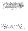
- Figs. 1 and 2 show several automotive exterior lighting applications including one in which a light emitting panel assembly 21 is mounted in a back end or bumper 22 of a vehicle 23 to provide running lights in the back end/bumper, another in which light emitting panel assemblies 24 are mounted in body panels 25 along the rear, front and/or sides of a vehicle to provide running lights or accent lights or to light a logo, step, running board, or other surface area of a vehicle; and still another in which a light emitting panel assembly 26 is mounted in a vehicle trunk lid 27 for providing a running light or illumination for a logo, accent light or license plate mounted on the trunk lid.
- the respective light emitting panel members 28, 29 and 30 are shaped to fit the particular application and may be made of a transparent resiliently deformable material such as a thermoplastic elastomer or silicone rubber that will flex upon impact during minor traffic accidents without breakage.
- the number and location of light sources 9 and associated light transition regions 10 for a given light emitting panel member may vary for a given application depending on the overall size and shape of each panel member and desired amount of light output therefrom.
- the back end/bumper running light application shown in Figs. 1 and 2 may only require one light source 9 and associated light transition region 10 at each end of the panel member 28, whereas the body panel and trunk lid running light applications shown in Figs. 1 and 2 may require a plurality of closely spaced light sources 9 and associated light transition regions 10 along one or more light input surfaces of the panel members.
- FIG. 1 and 2 show several such light sources and associated light transition regions along the back edges of the panel members 29 used to provide running taillights for a vehicle and along a top edge of the panel member 30 used to provide illumination on a trunk lid.
- Mounting all of the light sources for the tail running lights along the back edges of the panel members 29 minimizes the risk that the light sources themselves will be damaged in the event the tail running lights are impacted during minor traffic accidents and the like.
- These panel members may have a relatively thin, low profile, for example, less than one quarter inch thick, so as not to take up much space.
- these panel members 29 may form the exterior surface of the body panel 25 as shown at the left hand side of Fig. 2 or a lens or film 34 may cover the panel members as shown at the right hand side of Fig. 2 .
- Fig. 1 shows the light source 9 at the left end of panel member 28 mechanically held in place by a holder 63 received in a slot in an edge of the panel member. Also a fiber optic light pipe 64 is shown at the right end of the panel member 28 of Fig. 1 for transmitting light to the panel member from a remote light source 65 located for example in the trunk or other remote location in the vehicle.
- An additional array of light sources 31 such as LEDs or incandescent or halogen lamps (with or without reflectors) may also be strategically mounted inwardly (i.e., behind) the inner surface of the light emitting panel members 29 and/or 30 to cause a more intense light to shine through the panel members and a back reflector or trans reflector 32 if provided on the panel members or through one or more clear areas or holes 33 through the panel members where no print pattern, back reflector or trans reflector is provided on the panel members as also schematically shown in Figs. 1 and 2 for specific applications, for example, to provide brake or turn signal lights, turning or backup illumination, etc.
- the panel member could be made of a rigid transparent material such as polycarbonate or acrylic plastic instead of a resiliently deformable material if desired.
Description
- This invention relates generally as indicated to light emitting panel assemblies especially for automotive applications.
- Light emitting panel assemblies are generally known. The present invention relates to certain improvements in light emitting panel assemblies especially for automotive applications. Also, this invention is concerned with passing/shining light directly through a light emitting panel member or through holes in the panel member for performing specified lighting functions, for example, providing brake or turn signal lights and/or turning or backup illumination for a vehicle.
- In accordance with the present invention there is provided a light emitting panel assembly according to claim 1.
- The light emitting panel assemblies may include a light emitting panel member made out of a suitable transparent resiliently deformable elastomeric material that absorbs impact without breakage. Such panel members are especially suitable for use in exterior automotive lighting applications to help eliminate damage to the panel member if impacted during a traffic accident.
- Examples where such a resiliently deformable panel member may be effectively used in exterior automotive lighting applications to reduce or eliminate damage to the panel member during accidents are running or accent lights in the bumper or other exterior body portions of a vehicle. The light emitting panel member may also be incorporated into a trunk lid of a vehicle to provide running lights and/or license plate or logo illumination in the trunk lid. In applications where the trunk lid is recessed, the panel member may be rigid. However, if the trunk lid is substantially flush with the body exterior, the panel member is desirably resiliently deformable to withstand impacts during accidents without breakage of the panel member.
- One or more light sources may be mounted within one or more light transition areas or regions adjacent one or more light input surfaces of a light emitting panel member.
- One or more light sources may be positioned adjacent one side of the panel member for causing light to shine through the panel member or through holes in the panel member for performing specified lighting functions, for example, providing brake or turn signal lights and/or turning or backup illumination for a vehicle.
- One or more light sources may be selectively positioned along an edge or side of the panel member for increasing the light output from selected light output areas/regions on one or both sides of the panel member.
- The light emitting panel member may have a secondary reflective/refractive surface for reflecting/refracting a portion of the light entering an input surface of the panel member around a corner of the panel member.
- To the accomplishment of the foregoing and related ends, the invention, then, comprises the features hereinafter fully described and particularly pointed out in the claims, the following description and the annexed drawing setting forth in detail certain illustrative embodiments of the invention, these being indicative, however, of but several of the various ways in which the principles of the invention may be employed.
- In the annexed drawings:
-
Fig. 1 is a schematic end view of a rear portion of a vehicle incorporating other forms of light emitting panel assemblies in accordance with this invention; -
Fig. 2 is a fragmentary transverse section through the vehicle end portion and panel assemblies ofFig. 1 taken on the plane of the line 4-4 thereof; - The light sources may be of any suitable type including, for example, any of the types disclosed in
U.S. Patent Nos. 4,897,771 and5,005,108 , assigned to the same assignee as the present application. In particular, the light sources may be nonlinear such as an arc lamp, an incandescent bulb which also may be colored, filtered or painted, a lens end bulb, a halogen lamp, a light emitting diode (LED), a chip from an LED, a neon bulb, a fiber optic light pipe transmitting light from a remote light source, a laser or laser diode, or linear such as a line light or fluorescent tube, or any other suitable light source. Also, the light sources may be a multiple colored LED, or a combination of multiple colored radiation sources in order to provide a desired colored or white light output distribution. For example, a plurality of colored lights such as LEDs of different colors (red, blue, green) or a single LED with multiple colored chips may be employed to create white light or any other color or shade light output distribution by varying the intensities of each individual colored light. - A pattern of light extracting deformities or disruptions may be provided on one or both sides of the panel members along the entire length thereof or at one or more selected areas of the panel members as desired. The terms deformities or disruptions are used interchangeably herein to mean any change in the shape or geometry of the panel surface and/or coating or surface treatment that causes a portion of the light to be emitted. A pattern of light extracting deformities may include a variable pattern which breaks up the light rays such that the internal angle of reflection of a portion of the light rays will be great enough to cause the light rays either to be emitted out of the panel members through the side or sides on which the light extraction deformities are provided or reflected back through the panel members and emitted out the other side.
- Such deformities or disruptions can be produced in a variety of manners, for example, by providing a painted pattern, an etched pattern, a machined pattern, a printed pattern, a painted pattern, a hot stamped pattern, or a molded pattern or the like at selected light output areas on the surfaces of the panel members. An ink or adhesive pattern or printed pattern may be applied for example by pad printing, silk screening, ink jet, photolithography, heat transfer film process or the like. The deformities may also be printed on a sheet or film which is used to apply the deformities to the sides of the panel members. This sheet or film may become a permanent part of the light panel assemblies for example by attaching or otherwise positioning the sheet or film against one or both sides of the panel members in order to produce a desired effect.
- By varying the density, opaqueness or translucence, shape, depth, color, area, index of refraction, or type of deformities on an area or areas of the panel members, the light output of the panel members can be controlled. The deformities or disruptions may be used to control the percent of light emitted from any surface area of the panel members. For example, less and/or smaller size deformities may be placed on panel surface areas where less light output is wanted. Conversely, a greater percentage of and/or larger deformities may be placed on surface areas of the panels where greater light output is desired.
- Varying the percentages and/or size of deformities in different surface areas of the panels is necessary in order to provide a uniform light output distribution. For example, the amount of light traveling through the panels will ordinarily be greater in areas closer to the light source than in other areas further removed from the light source. A pattern of light extracting deformities may be used to adjust for the light variances within the panel members, for example, by providing a denser concentration of light extracting deformities with increased distance from the light source thereby resulting in a more uniform light output distribution from the light emitting panels.
- The deformities may also be used to control the output ray angle distribution of the emitted light to suit a particular application.
- Additionally, the pattern of light extracting deformities may be used to adjust for light output variances attributed to light extractions of the panel members. The pattern of light extracting deformities may be printed on the light output surface areas utilizing a wide spectrum of paints, inks, coatings, epoxies, adhesives, or the like, ranging from glossy to opaque or both, and may employ half-tone separation techniques to vary the deformity coverage. If an adhesive is used to provide a pattern of light extracting deformities, the adhesive may also be used to secure a back reflector to the panel member. Moreover, the pattern of light extracting deformities may be multiple layers or vary in index of refraction.
- Print patterns of light extracting deformities may vary in shapes such as dots, squares, diamonds, ellipses, stars, random shapes, and the like, and are desirably .006 square inch per deformity/element or less. Also, print patterns that are 60 lines per inch or finer are desirably employed, thus making the deformities or shapes in the print patterns nearly invisible to the human eye in a particular application thereby eliminating the detection of gradient or banding lines that are common to light extracting patterns utilizing larger elements. Additionally, the deformities may vary in shape and/or size along the length and/or width of the panel members. Also, a random placement pattern of the deformities may be utilized throughout the length and/or width of the panel members. The deformities may have shapes or a pattern with no specific angles to reduce moire or other interference effects. Examples of methods to create these random patterns are printing a pattern of shapes using stochastic print pattern techniques, frequency modulated half tone patterns, or random dot half tones. Moreover, the deformities may be colored in order to effect color correction in the panel members. The color of the deformities may also vary throughout the panel members, for example to provide different colors for the same or different light output surface areas.
- In addition to or in lieu of these light extracting deformities, other light extracting deformities including prismatic surfaces, depressions or raised surfaces of various shapes using more complex shapes in a mold pattern may be molded, etched, stamped, thermoformed, hot stamped or the like into or on one or more surface areas of the panel members. The prismatic surfaces, depressions or raised surfaces will cause a portion of the light rays contacted thereby to be emitted from the panel members. Also, the angles of the prisms, depressions or other surfaces may be varied to direct the light in different directions to produce a desired light output distribution or effect. Moreover, the reflective or refractive surfaces may have shapes or a pattern with no specific angles to reduce moire or other interference effects.
- A back reflector or reflective coating (including trans reflectors) may be applied to a bottom side of the panel members using a suitable adhesive or other method in order to improve light output efficiency of the panel assemblies by reflecting the light emitted from that side back through the panel members for emission through the opposite side. If adhesive is used to adhere the back reflector to the panel members, the adhesive is desirably applied only along the side edges of the panel members so that there is a slight air gap between the back reflector and panel members except where there is adhesive, since the adhesive changes the internal critical angle of the light in a less controllable manner than the air gap between the panel surface and back reflector.
- Additionally, a pattern of light extracting deformities may be provided on one or both sides of the panel members in order to change the path of the light so that the internal critical angle is exceeded and a portion of the light is emitted from one or both sides of the panel members. Where the deformities are created by a print pattern, the back reflector can be the same color as the print pattern so that print pattern is not visible through the back reflector. Moreover, a transparent film, sheet or plate may be attached or positioned against the side or sides of the panel members from which light is emitted using a suitable adhesive or other method in order to produce a desired effect.
- The transparent film may be used to further improve the uniformity of the light output distribution or change the output ray angle distribution. For example, the film may be a colored film, a diffuser, or a label or display, a portion of which may be a transparent overlay that may be colored and/or have text or an image thereon. Also the film may be a prismatic or lenticular lens or other device that changes the output ray angle distribution.
-
Figs. 1 and 2 show several automotive exterior lighting applications including one in which a light emittingpanel assembly 21 is mounted in a back end orbumper 22 of avehicle 23 to provide running lights in the back end/bumper, another in which light emittingpanel assemblies 24 are mounted inbody panels 25 along the rear, front and/or sides of a vehicle to provide running lights or accent lights or to light a logo, step, running board, or other surface area of a vehicle; and still another in which a light emittingpanel assembly 26 is mounted in avehicle trunk lid 27 for providing a running light or illumination for a logo, accent light or license plate mounted on the trunk lid. In each case the respective light emittingpanel members - The number and location of
light sources 9 and associatedlight transition regions 10 for a given light emitting panel member may vary for a given application depending on the overall size and shape of each panel member and desired amount of light output therefrom. For example, the back end/bumper running light application shown inFigs. 1 and 2 may only require onelight source 9 and associatedlight transition region 10 at each end of thepanel member 28, whereas the body panel and trunk lid running light applications shown inFigs. 1 and 2 may require a plurality of closely spacedlight sources 9 and associatedlight transition regions 10 along one or more light input surfaces of the panel members.Figs. 1 and 2 show several such light sources and associated light transition regions along the back edges of thepanel members 29 used to provide running taillights for a vehicle and along a top edge of thepanel member 30 used to provide illumination on a trunk lid. Mounting all of the light sources for the tail running lights along the back edges of the panel members 29 (i.e., the edges closest to the trunk lid) minimizes the risk that the light sources themselves will be damaged in the event the tail running lights are impacted during minor traffic accidents and the like. These panel members may have a relatively thin, low profile, for example, less than one quarter inch thick, so as not to take up much space. Also, thesepanel members 29 may form the exterior surface of thebody panel 25 as shown at the left hand side ofFig. 2 or a lens or film 34 may cover the panel members as shown at the right hand side ofFig. 2 . - In the usual case the light sources are embedded, potted or bonded in the light transition regions of the panels as previously described. However,
Fig. 1 shows thelight source 9 at the left end ofpanel member 28 mechanically held in place by aholder 63 received in a slot in an edge of the panel member. Also a fiber opticlight pipe 64 is shown at the right end of thepanel member 28 ofFig. 1 for transmitting light to the panel member from a remotelight source 65 located for example in the trunk or other remote location in the vehicle. - An additional array of
light sources 31 such as LEDs or incandescent or halogen lamps (with or without reflectors) may also be strategically mounted inwardly (i.e., behind) the inner surface of the light emittingpanel members 29 and/or 30 to cause a more intense light to shine through the panel members and a back reflector or trans reflector 32 if provided on the panel members or through one or more clear areas or holes 33 through the panel members where no print pattern, back reflector or trans reflector is provided on the panel members as also schematically shown inFigs. 1 and 2 for specific applications, for example, to provide brake or turn signal lights, turning or backup illumination, etc. By locating thelight sources 9 for illuminating thepanel members 29 themselves adjacent one or more ends of the panel members, they will not interfere with or obstruct the visibility of the array oflight sources 31 shining through the panel members. - In automotive applications such as a
trunk lid 27 where the light emittingpanel assembly 26 may be sufficiently recessed such that the light emittingpanel member 30 will typically not be impacted during minor traffic accidents, the panel member could be made of a rigid transparent material such as polycarbonate or acrylic plastic instead of a resiliently deformable material if desired.
Claims (5)
- A light emitting panel assembly (24) mounted on a body portion (25) of a vehicle (23), said panel assembly (24) comprising at least one solid light emitting panel member (29) having at least one light input surface, top and bottom surfaces and a greater cross sectional width than thickness, a light source (9) and associated light transition region (10) for receiving light from said light source and transmitting such light into said light input surface for conduction through said panel assembly (24) from an edge of said panel assembly for emission of the light from one of said top and bottom surfaces of said panel member (29), characterised in that said panel member (29) is located on an exterior surface of said body portion (25) with said panel member (29) conforming to a curved profile of said vehicle (23) to provide illumination along said curved profile.
- The assembly of claim 1 characterised in that said light source (9) is adjacent an edge or side of said panel member (29).
- The assembly of claim 1 or 2 characterised in that said panel member (29) is wrapped around a corner of said vehicle (23) to provide illumination around said corner.
- The assembly of claims 1 to 3, further characterised by another light source (30) located directly behind said panel member (29) for shining light through said panel member (29) independently of the light emitted by said panel member (29) from said light source (9).
- The assembly of claims 1 to 4 further characterised by a transparent substrate (34) overlying at least one surface of said panel member (29).
Priority Applications (1)
| Application Number | Priority Date | Filing Date | Title |
|---|---|---|---|
| EP08005524A EP1975958A3 (en) | 1996-01-16 | 1997-01-07 | Light emitting panel assemblies for use in automotive applications and the like |
Applications Claiming Priority (3)
| Application Number | Priority Date | Filing Date | Title |
|---|---|---|---|
| US08/585,062 US5895115A (en) | 1996-01-16 | 1996-01-16 | Light emitting panel assemblies for use in automotive applications and the like |
| US585062 | 1996-01-16 | ||
| EP97300059A EP0801373B1 (en) | 1996-01-16 | 1997-01-07 | Light emitting panel assemblies for use in automotive applications |
Related Parent Applications (1)
| Application Number | Title | Priority Date | Filing Date |
|---|---|---|---|
| EP97300059A Division EP0801373B1 (en) | 1996-01-16 | 1997-01-07 | Light emitting panel assemblies for use in automotive applications |
Related Child Applications (1)
| Application Number | Title | Priority Date | Filing Date |
|---|---|---|---|
| EP08005524A Division EP1975958A3 (en) | 1996-01-16 | 1997-01-07 | Light emitting panel assemblies for use in automotive applications and the like |
Publications (3)
| Publication Number | Publication Date |
|---|---|
| EP1443482A2 EP1443482A2 (en) | 2004-08-04 |
| EP1443482A3 EP1443482A3 (en) | 2005-04-06 |
| EP1443482B1 true EP1443482B1 (en) | 2009-03-04 |
Family
ID=24339897
Family Applications (3)
| Application Number | Title | Priority Date | Filing Date |
|---|---|---|---|
| EP08005524A Withdrawn EP1975958A3 (en) | 1996-01-16 | 1997-01-07 | Light emitting panel assemblies for use in automotive applications and the like |
| EP04007904A Expired - Lifetime EP1443482B1 (en) | 1996-01-16 | 1997-01-07 | Light emitting panel assemblies for use in automotive applications and the like |
| EP97300059A Expired - Lifetime EP0801373B1 (en) | 1996-01-16 | 1997-01-07 | Light emitting panel assemblies for use in automotive applications |
Family Applications Before (1)
| Application Number | Title | Priority Date | Filing Date |
|---|---|---|---|
| EP08005524A Withdrawn EP1975958A3 (en) | 1996-01-16 | 1997-01-07 | Light emitting panel assemblies for use in automotive applications and the like |
Family Applications After (1)
| Application Number | Title | Priority Date | Filing Date |
|---|---|---|---|
| EP97300059A Expired - Lifetime EP0801373B1 (en) | 1996-01-16 | 1997-01-07 | Light emitting panel assemblies for use in automotive applications |
Country Status (5)
| Country | Link |
|---|---|
| US (6) | US5895115A (en) |
| EP (3) | EP1975958A3 (en) |
| JP (3) | JP4326602B2 (en) |
| DE (2) | DE69739290D1 (en) |
| TW (1) | TW350822B (en) |
Families Citing this family (258)
| Publication number | Priority date | Publication date | Assignee | Title |
|---|---|---|---|---|
| US20120020101A1 (en) * | 1994-11-02 | 2012-01-26 | Magna Mirrors Of America, Inc. | Vehicle exterior mirror system |
| US9586526B2 (en) | 1995-04-21 | 2017-03-07 | Magna Mirrors Of America, Inc. | Vehicle exterior mirror system |
| US5895115A (en) * | 1996-01-16 | 1999-04-20 | Lumitex, Inc. | Light emitting panel assemblies for use in automotive applications and the like |
| US6550949B1 (en) * | 1996-06-13 | 2003-04-22 | Gentex Corporation | Systems and components for enhancing rear vision from a vehicle |
| US5803579A (en) * | 1996-06-13 | 1998-09-08 | Gentex Corporation | Illuminator assembly incorporating light emitting diodes |
| US20040239243A1 (en) * | 1996-06-13 | 2004-12-02 | Roberts John K. | Light emitting assembly |
| US7038398B1 (en) * | 1997-08-26 | 2006-05-02 | Color Kinetics, Incorporated | Kinetic illumination system and methods |
| CA2320153A1 (en) * | 1997-12-31 | 1999-07-08 | Gentex Corporation | Vehicle vision system |
| EP0942474B1 (en) * | 1998-03-11 | 2006-04-19 | Siemens Aktiengesellschaft | Light emitting diode |
| US6050702A (en) * | 1998-04-21 | 2000-04-18 | Rahmonic Resources Pte. Ltd. | Apparatus and method to provide custom lighting |
| WO2000012226A1 (en) * | 1998-08-28 | 2000-03-09 | Fed Corporation | Full color organic light emitting diode display and method for making the same using inkjet fabrication |
| DE60026689T2 (en) * | 1999-01-14 | 2006-11-23 | Federal-Mogul Corp., Southfield | LIGHTING SYSTEMS FOR MOTOR VEHICLES |
| DE19902244A1 (en) * | 1999-01-21 | 2000-08-03 | Daimler Chrysler Ag | Headlining with a transparent roof element |
| DE19910241A1 (en) * | 1999-03-08 | 2000-09-21 | Mannesmann Vdo Ag | Display unit with a display front and method for producing such a display front |
| US6296380B1 (en) * | 1999-03-18 | 2001-10-02 | Aboud Dawli | Lighted steering wheel |
| US6499852B1 (en) * | 1999-09-07 | 2002-12-31 | Toyoda Gosei Co., Ltd. | Vehicle display lighting device |
| GB2356965B (en) * | 1999-12-03 | 2003-10-08 | Ncr Int Inc | Self-service terminal |
| DE19958725A1 (en) * | 1999-12-06 | 2001-06-07 | Mannesmann Vdo Ag | Control unit with illuminated controls |
| WO2001071243A1 (en) * | 2000-03-23 | 2001-09-27 | Forsythe John D | Security flashlight and method |
| US6520669B1 (en) * | 2000-06-19 | 2003-02-18 | Light Sciences Corporation | Flexible substrate mounted solid-state light sources for exterior vehicular lighting |
| US6454422B1 (en) * | 2000-10-26 | 2002-09-24 | Trw Inc. | Backlit indicia on a painted surface |
| US6652128B2 (en) * | 2001-01-31 | 2003-11-25 | Textron Automotive Company, Inc. | Backlighting method for an automotive trim panel |
| KR20030093251A (en) * | 2001-03-28 | 2003-12-06 | 바바라 섹스톤 | Computer |
| US7336980B1 (en) | 2001-05-29 | 2008-02-26 | Nokia Corporation | Outer decorative cover for attachment to a wireless communication device including a printed circuit board and an associated light source mounted in an interior of the wireless device |
| US6461028B1 (en) * | 2001-06-15 | 2002-10-08 | Chin-Jeng Huang | Vehicle side bumper and signal light assembly |
| US6854870B2 (en) * | 2001-06-30 | 2005-02-15 | Donnelly Corporation | Vehicle handle assembly |
| US6790396B2 (en) | 2001-08-29 | 2004-09-14 | Nokia Corporation | Method of making illuminated covers |
| DE60223050T2 (en) * | 2001-08-31 | 2008-07-17 | Gentex Corp., Zeeland | VEHICLE LIGHT ARRANGEMENT WITH COOLING BODY |
| US6519140B1 (en) * | 2001-09-13 | 2003-02-11 | Sun Microsystems, Inc. | Hinged bezel for a computer system |
| JP4067802B2 (en) * | 2001-09-18 | 2008-03-26 | 松下電器産業株式会社 | Lighting device |
| US6874926B2 (en) * | 2001-11-26 | 2005-04-05 | Nokia Corporation | Illumination system for an electronic device |
| US6864787B1 (en) * | 2001-12-05 | 2005-03-08 | Sherri Coseo Veach | Front safety brake lights |
| US6816083B2 (en) | 2002-02-04 | 2004-11-09 | Nokia Corporation | Electronic device with cover including a radio frequency indentification module |
| US6864496B2 (en) * | 2002-05-01 | 2005-03-08 | Chris Levine | Lighting effect generator |
| US6905237B2 (en) * | 2002-08-26 | 2005-06-14 | William Alan Jacobs | Fiber optic lighting radial arrangement and method for forming the same |
| DE10240270A1 (en) * | 2002-08-31 | 2004-03-18 | Johnson Controls Gmbh | Internal lining component for vehicle has base in form of light-conducting panel which is connected to light source, flexible and compressible cover being fitted over panel |
| US6836611B2 (en) * | 2002-10-03 | 2004-12-28 | J. W. Speaker Corporation | Light guide and lateral illuminator |
| US6910783B2 (en) * | 2002-10-04 | 2005-06-28 | Lumitex, Inc. | Transparent light emitting members and method of manufacture |
| US7406245B2 (en) | 2004-07-27 | 2008-07-29 | Lumitex, Inc. | Flat optical fiber light emitters |
| US20070248307A1 (en) * | 2002-10-04 | 2007-10-25 | Page David J | Transparent light emitting members and method of manufacture |
| TW547774U (en) * | 2002-10-23 | 2003-08-11 | Benq Corp | Light emitting diode |
| US20040085746A1 (en) * | 2002-11-05 | 2004-05-06 | Chen Shih Ling | Instrument panel with colorful illumination |
| US7671859B2 (en) * | 2002-11-06 | 2010-03-02 | Continental Automotive Systems Us, Inc. | Thin instrument cluster with anti-reflective coating |
| US20040108970A1 (en) * | 2002-12-04 | 2004-06-10 | Nealon Brian Clark | Vehical graphical message display system |
| US6975369B1 (en) * | 2002-12-12 | 2005-12-13 | Gelcore, Llc | Liquid crystal display with color backlighting employing light emitting diodes |
| US6974220B2 (en) * | 2002-12-12 | 2005-12-13 | Siemens Vdo Automotive Corporation | Bright pointer for instrument cluster |
| US7417782B2 (en) | 2005-02-23 | 2008-08-26 | Pixtronix, Incorporated | Methods and apparatus for spatial light modulation |
| US6737592B1 (en) * | 2003-03-14 | 2004-05-18 | Motorola, Inc. | Switch assembly for operating a device in different operational modes |
| US20040200121A1 (en) * | 2003-03-20 | 2004-10-14 | Lord Octave E. | Lighted downrigger counter |
| EP1462297A3 (en) * | 2003-03-26 | 2007-05-09 | Calsonic Kansei Corporation | Information displaying apparatus for a vehicle |
| US7018086B2 (en) * | 2003-06-13 | 2006-03-28 | Toppoly Optoelectronics Corp. | Back light module and liquid crystal display |
| US20040264163A1 (en) * | 2003-06-26 | 2004-12-30 | Te-Hsiang Fang | Light guide |
| AU2004205205B2 (en) * | 2003-08-26 | 2009-06-04 | Lg Electronics Inc. | Control panel assembly and method for controlling thereof |
| US20050073826A1 (en) * | 2003-10-06 | 2005-04-07 | Kuo Heng Sheng | Light guide plate with multiple visible regions |
| US7025485B2 (en) * | 2003-10-29 | 2006-04-11 | Guide Corporation | High mount stop lamp with printed circuit board |
| US7252400B2 (en) * | 2003-11-03 | 2007-08-07 | Delphi Technologies, Inc. | Illuminated indicator |
| US7029284B2 (en) * | 2003-11-17 | 2006-04-18 | Methode Electronics, Inc. | Floating contact assembly for a steering wheel |
| US7708437B2 (en) * | 2003-11-19 | 2010-05-04 | Lear Corporation | Instrument panel system having concealed switches |
| US7182492B1 (en) * | 2003-12-22 | 2007-02-27 | Robert Louis Walter | License plate system having enhanced illumination |
| DE102004012467B4 (en) * | 2004-03-15 | 2007-05-31 | Daimlerchrysler Ag | Vehicle film component and method for its production |
| US20050222801A1 (en) * | 2004-04-06 | 2005-10-06 | Thomas Wulff | System and method for monitoring a mobile computing product/arrangement |
| CA2579217C (en) | 2004-04-30 | 2014-04-29 | Oy Modilis Ltd. | Ultrathin lighting element |
| US7044620B2 (en) * | 2004-04-30 | 2006-05-16 | Guide Corporation | LED assembly with reverse circuit board |
| US7084360B2 (en) * | 2004-07-28 | 2006-08-01 | Lear Corporation | Elastomeric vehicle control switch |
| US20060055665A1 (en) * | 2004-09-14 | 2006-03-16 | Xerox Corporation. | User interface having button delineating control panel |
| WO2006041876A1 (en) * | 2004-10-06 | 2006-04-20 | Johnson Controls Technology Company | Instrument cluster with translucent or transparent sheet |
| DE102004053089A1 (en) * | 2004-11-03 | 2006-05-04 | Sidler Gmbh & Co. Kg | Motor vehicle light |
| US7093948B2 (en) * | 2004-12-15 | 2006-08-22 | Yazaki North America, Inc. | Display device with light guide |
| US7828470B2 (en) * | 2005-01-24 | 2010-11-09 | Flextronics Automotive Inc. | Electronic indicator with backlighting |
| US7374324B2 (en) * | 2005-02-09 | 2008-05-20 | Dura Global Technologies, Inc. | LED molded light guide |
| US7742016B2 (en) | 2005-02-23 | 2010-06-22 | Pixtronix, Incorporated | Display methods and apparatus |
| US7999994B2 (en) | 2005-02-23 | 2011-08-16 | Pixtronix, Inc. | Display apparatus and methods for manufacture thereof |
| US9229222B2 (en) | 2005-02-23 | 2016-01-05 | Pixtronix, Inc. | Alignment methods in fluid-filled MEMS displays |
| US7304786B2 (en) | 2005-02-23 | 2007-12-04 | Pixtronix, Inc. | Methods and apparatus for bi-stable actuation of displays |
| US7616368B2 (en) * | 2005-02-23 | 2009-11-10 | Pixtronix, Inc. | Light concentrating reflective display methods and apparatus |
| US8519945B2 (en) | 2006-01-06 | 2013-08-27 | Pixtronix, Inc. | Circuits for controlling display apparatus |
| US20070205969A1 (en) * | 2005-02-23 | 2007-09-06 | Pixtronix, Incorporated | Direct-view MEMS display devices and methods for generating images thereon |
| US7502159B2 (en) | 2005-02-23 | 2009-03-10 | Pixtronix, Inc. | Methods and apparatus for actuating displays |
| US20060209012A1 (en) * | 2005-02-23 | 2006-09-21 | Pixtronix, Incorporated | Devices having MEMS displays |
| US8482496B2 (en) | 2006-01-06 | 2013-07-09 | Pixtronix, Inc. | Circuits for controlling MEMS display apparatus on a transparent substrate |
| US7746529B2 (en) | 2005-02-23 | 2010-06-29 | Pixtronix, Inc. | MEMS display apparatus |
| US8310442B2 (en) | 2005-02-23 | 2012-11-13 | Pixtronix, Inc. | Circuits for controlling display apparatus |
| US9158106B2 (en) | 2005-02-23 | 2015-10-13 | Pixtronix, Inc. | Display methods and apparatus |
| US8159428B2 (en) | 2005-02-23 | 2012-04-17 | Pixtronix, Inc. | Display methods and apparatus |
| US7304785B2 (en) | 2005-02-23 | 2007-12-04 | Pixtronix, Inc. | Display methods and apparatus |
| US9261694B2 (en) | 2005-02-23 | 2016-02-16 | Pixtronix, Inc. | Display apparatus and methods for manufacture thereof |
| US7271945B2 (en) | 2005-02-23 | 2007-09-18 | Pixtronix, Inc. | Methods and apparatus for actuating displays |
| US7405852B2 (en) | 2005-02-23 | 2008-07-29 | Pixtronix, Inc. | Display apparatus and methods for manufacture thereof |
| US7755582B2 (en) | 2005-02-23 | 2010-07-13 | Pixtronix, Incorporated | Display methods and apparatus |
| US9082353B2 (en) | 2010-01-05 | 2015-07-14 | Pixtronix, Inc. | Circuits for controlling display apparatus |
| US7675665B2 (en) | 2005-02-23 | 2010-03-09 | Pixtronix, Incorporated | Methods and apparatus for actuating displays |
| US20060203502A1 (en) * | 2005-03-10 | 2006-09-14 | Stevens Peter M | Total internal reflection license plate frame |
| KR100692742B1 (en) * | 2005-05-13 | 2007-03-09 | 삼성전자주식회사 | Keypad having light guide layer and keypad assembly |
| ATE401659T1 (en) * | 2005-05-19 | 2008-08-15 | Samsung Electronics Co Ltd | KEYBOARD AND KEYBOARD ARRANGEMENT |
| KR100629053B1 (en) | 2005-05-19 | 2006-09-26 | 삼성전자주식회사 | Key-pad assembly |
| KR100689392B1 (en) * | 2005-05-19 | 2007-03-02 | 삼성전자주식회사 | Key-pad and key-pad assembly using the same |
| US20060291241A1 (en) * | 2005-06-22 | 2006-12-28 | Carmanah Technologies Corp. | Light emitting diode illuminated display panel assembly |
| US20060289054A1 (en) * | 2005-06-22 | 2006-12-28 | Carmanah Technologies Corp. | Solar powered light emitting diode illuminated display panel assembly |
| KR100689394B1 (en) * | 2005-06-28 | 2007-03-02 | 삼성전자주식회사 | Keypad assembly for mobile phone |
| US20060290647A1 (en) * | 2005-06-28 | 2006-12-28 | Kilolambda Technologies Ltd. | Optical waveguided dashboard display |
| US7385489B2 (en) * | 2005-07-22 | 2008-06-10 | Visteon Global Technologies, Inc. | Instrument panel assembly |
| US7486280B2 (en) * | 2005-08-04 | 2009-02-03 | Uniplas Enterprises Pte, Ltd. | Contoured capacitive touch control panel |
| US7488083B2 (en) * | 2005-08-22 | 2009-02-10 | Gentex Corporation | Vehicular rearview components and assemblies |
| EP1920187B2 (en) * | 2005-08-31 | 2018-09-12 | Osram Sylvania, Inc. | Led headlamp system |
| KR100678197B1 (en) * | 2005-09-23 | 2007-02-02 | 삼성전자주식회사 | Backlighting device for keypad |
| US7934439B2 (en) * | 2005-11-10 | 2011-05-03 | Tk Holdings Inc. | Back light of steering wheel |
| WO2007077466A2 (en) * | 2006-01-06 | 2007-07-12 | Pilkington Automotive Deutschland Gmbh | Glazing |
| US20070160334A1 (en) * | 2006-01-10 | 2007-07-12 | Cobb Weston T | End-emitting fiber optic indicia for motor vehicles |
| US8409088B2 (en) | 2006-01-18 | 2013-04-02 | Invuity, Inc. | Retractor illumination system |
| US20100225499A1 (en) * | 2006-01-27 | 2010-09-09 | Koninklijke Philips Electronics N.V. | Device for inputting control commands |
| US7374304B2 (en) * | 2006-02-22 | 2008-05-20 | Yazaki North America, Inc. | Display with housing having cavity for secondary light source |
| US8526096B2 (en) | 2006-02-23 | 2013-09-03 | Pixtronix, Inc. | Mechanical light modulators with stressed beams |
| CA2540268A1 (en) * | 2006-03-22 | 2007-09-22 | Realights Inc. | Lighting process by insertion of electroluminescent diodes in acrylic |
| US7494256B1 (en) * | 2006-04-05 | 2009-02-24 | Yazaki North America, Inc. | Illuminated instrument cluster with perceived 3-D display segments |
| US20070243844A1 (en) * | 2006-04-12 | 2007-10-18 | Nokia Corporation | Flexible optical illumination system |
| US7530702B2 (en) * | 2006-05-12 | 2009-05-12 | Visteon Global Technologies, Inc. | Display over gage instrument cluster |
| FR2901010B1 (en) * | 2006-05-15 | 2015-03-06 | Faurecia Interieur Ind | LUMINOUS SIGNALING DEVICE ON A SOFT SKIN AND METHOD OF MANUFACTURING THE SAME |
| US8047987B2 (en) | 2006-05-26 | 2011-11-01 | Invuity, Inc. | Blade insert illuminator |
| US7876489B2 (en) | 2006-06-05 | 2011-01-25 | Pixtronix, Inc. | Display apparatus with optical cavities |
| DE102006026910B4 (en) * | 2006-06-09 | 2020-04-02 | BSH Hausgeräte GmbH | Control unit for a household appliance |
| US8594742B2 (en) * | 2006-06-21 | 2013-11-26 | Symbol Technologies, Inc. | System and method for monitoring a mobile device |
| US7556412B2 (en) * | 2006-07-20 | 2009-07-07 | Int America, Llc | Fiber optic auxiliary lighting system |
| US20080026189A1 (en) * | 2006-07-27 | 2008-01-31 | Chun-Wei Lin | Thin key structure for generating dazzling light |
| US20080037266A1 (en) * | 2006-08-09 | 2008-02-14 | Cunnien Cole J | Lit Running Board |
| EP2057075A4 (en) | 2006-08-21 | 2010-10-20 | Gary W Nelson | Cutlery receptacle |
| WO2008024761A2 (en) | 2006-08-21 | 2008-02-28 | Innotec Corporation | Electrical device having boardless electrical component mounting arrangement |
| US7498534B2 (en) * | 2006-08-30 | 2009-03-03 | 3M Innovative Properties Company | Keypad light guide |
| KR101228452B1 (en) * | 2006-09-12 | 2013-01-31 | 엘지전자 주식회사 | Keypad assembly and mobile terminal having it |
| EP2080045A1 (en) | 2006-10-20 | 2009-07-22 | Pixtronix Inc. | Light guides and backlight systems incorporating light redirectors at varying densities |
| US20080101759A1 (en) * | 2006-10-26 | 2008-05-01 | K Laser Technology, Inc. | Prism matrix with random phase structures |
| KR100749124B1 (en) * | 2006-11-02 | 2007-08-13 | (주)아토콘 | Light guide key-plate and light emitting keypad comprising the same |
| US7852546B2 (en) | 2007-10-19 | 2010-12-14 | Pixtronix, Inc. | Spacers for maintaining display apparatus alignment |
| US9176318B2 (en) | 2007-05-18 | 2015-11-03 | Pixtronix, Inc. | Methods for manufacturing fluid-filled MEMS displays |
| US20100107806A1 (en) * | 2007-01-26 | 2010-05-06 | Corinaldi Alessandro Alcide Gi | Vehicle Steering-Wheel Cover |
| JP4743132B2 (en) * | 2007-02-15 | 2011-08-10 | ティアック株式会社 | Electronic device having a plurality of function keys |
| US8408773B2 (en) * | 2007-03-19 | 2013-04-02 | Innotec Corporation | Light for vehicles |
| US7712933B2 (en) * | 2007-03-19 | 2010-05-11 | Interlum, Llc | Light for vehicles |
| US7647881B2 (en) * | 2007-05-09 | 2010-01-19 | Visteon Global Technologies | Dimensional enhancement lens |
| US8058360B2 (en) * | 2007-06-01 | 2011-11-15 | Grupo Petrotemex, S.A. De C.V. | Polyester blends exhibiting low temperature toughness |
| US8267462B2 (en) * | 2007-07-29 | 2012-09-18 | Gieorgii Bogdan | Versatile vehicle body protector and method of using same |
| JP5199364B2 (en) * | 2007-09-06 | 2013-05-15 | タカタ・ペトリ アーゲー | Vehicle steering wheel assembly |
| US7880635B2 (en) * | 2007-09-07 | 2011-02-01 | Visteon Global Technologies, Inc. | Color messaging lens |
| US8088066B2 (en) | 2007-10-24 | 2012-01-03 | Invuity, Inc. | Blade insert illuminator |
| US7671290B2 (en) * | 2007-10-29 | 2010-03-02 | Research In Motion Limited | Illuminated key-pad assembly |
| WO2009076579A2 (en) | 2007-12-12 | 2009-06-18 | Innotec Corporation | Overmolded circuit board and method |
| US7815339B2 (en) | 2008-01-09 | 2010-10-19 | Innotec Corporation | Light module |
| US8851734B2 (en) * | 2008-03-27 | 2014-10-07 | Skc Haas Display Films Co., Ltd. | Light guiding film having light extraction features |
| US8248560B2 (en) | 2008-04-18 | 2012-08-21 | Pixtronix, Inc. | Light guides and backlight systems incorporating prismatic structures and light redirectors |
| US8172440B2 (en) * | 2008-06-16 | 2012-05-08 | Ford Global Technologies, Llc | Concealed illuminated center high mount stop lamp (CHMSL) |
| GB2461316A (en) * | 2008-06-27 | 2009-12-30 | Visteon Global Tech Inc | Back-lit Display |
| US8178802B2 (en) * | 2008-07-31 | 2012-05-15 | Electrolux Home Products, Inc. | Unitized appliance control panel assembly and components of the assembly |
| US11382711B2 (en) | 2008-08-13 | 2022-07-12 | Invuity, Inc. | Cyclo olefin polymer and copolymer medical devices |
| US8092035B2 (en) * | 2008-09-10 | 2012-01-10 | Man-D-Tec | Illumination method and assembly |
| US9004713B2 (en) | 2008-09-10 | 2015-04-14 | Man-D-Tec, Inc. | Illumination assembly |
| US8128297B2 (en) * | 2008-09-11 | 2012-03-06 | Zippy Technology Corp. | Self-luminous keyboard with brightness-enhanced keycaps |
| US8411038B2 (en) | 2008-09-16 | 2013-04-02 | Angell-Demmel North America Corporation | Multi-layer integral keypad |
| US8061861B2 (en) * | 2008-10-27 | 2011-11-22 | Autoliv Asp, Inc. | Method for illuminating colors in a backlit driver airbag emblem |
| US8169679B2 (en) | 2008-10-27 | 2012-05-01 | Pixtronix, Inc. | MEMS anchors |
| US20110205259A1 (en) * | 2008-10-28 | 2011-08-25 | Pixtronix, Inc. | System and method for selecting display modes |
| TWM353585U (en) * | 2008-10-31 | 2009-03-21 | Askey Computer Corp | Injection component |
| US8909009B2 (en) | 2008-12-18 | 2014-12-09 | 3M Innovative Properties Company | Light guides having enhanced light extraction |
| CN102307756B (en) * | 2009-01-06 | 2014-06-18 | 江森自控科技公司 | Headliner with integral wire harness |
| US8142036B2 (en) * | 2009-03-12 | 2012-03-27 | Avago Technologies Ecbu Ip (Singapore) Pte. Ltd. | Keypad device with light source and reflector |
| DE102009036212B3 (en) * | 2009-08-05 | 2011-02-03 | Trw Automotive Electronics & Components Gmbh | Tactile switch group and their use as a control panel in motor vehicles |
| US8786401B2 (en) | 2009-12-23 | 2014-07-22 | Magna Mirrors Of America, Inc. | Extendable flush door handle for vehicle |
| KR20120132680A (en) | 2010-02-02 | 2012-12-07 | 픽스트로닉스 인코포레이티드 | Methods for manufacturing cold seal fluid-filled display apparatus |
| CN104916258B (en) | 2010-02-02 | 2018-02-16 | 追踪有限公司 | For controlling the circuit of display device |
| US20110205756A1 (en) * | 2010-02-19 | 2011-08-25 | Pixtronix, Inc. | Light guides and backlight systems incorporating prismatic structures and light redirectors |
| US8545305B2 (en) | 2010-06-28 | 2013-10-01 | Wms Gaming Inc. | Devices, systems, and methods for dynamically simulating a component of a wagering game |
| JP2012033420A (en) * | 2010-08-02 | 2012-02-16 | Hitachi Consumer Electronics Co Ltd | Lighting system and display device using this |
| JP2012123372A (en) * | 2010-11-16 | 2012-06-28 | Nikon Corp | Light emitting mechanism for operation section and operation mechanism |
| AU2010365156A1 (en) * | 2010-12-06 | 2013-06-27 | Construction Research & Technology Gmbh | Method for preparing admixture blends for construction material on site and a micro-plant for implementing the method |
| US8419103B2 (en) * | 2011-01-27 | 2013-04-16 | Nissan North America, Inc. | Panel assembly for a motor vehicle |
| CN103890652A (en) * | 2011-10-27 | 2014-06-25 | 罗伯特·博世有限公司 | Front cover for a housing enclosing a camera |
| US9171418B2 (en) | 2011-12-15 | 2015-10-27 | Bally Gaming, Inc. | Gaming devices and gaming systems with multiple display device arrangement |
| US9896045B2 (en) * | 2012-03-15 | 2018-02-20 | Carling Technologies, Inc. | Touch activated, wireless switches |
| JP5921372B2 (en) * | 2012-03-27 | 2016-05-24 | タカタ株式会社 | Airbag device, fastening structure and fastening member |
| WO2013188678A1 (en) | 2012-06-13 | 2013-12-19 | Innotec, Corp. | Flexible light pipe |
| CN103533789B (en) * | 2012-07-03 | 2016-11-09 | 江苏道康发电机组有限公司 | Electronic product panel |
| US9308857B2 (en) | 2012-10-23 | 2016-04-12 | Tk Holdings Inc. | Steering wheel light bar |
| US9233638B2 (en) | 2012-10-23 | 2016-01-12 | Tk Holdings Inc. | Steering wheel light bar |
| US9308856B2 (en) | 2012-10-23 | 2016-04-12 | Tk Holdings, Inc. | Steering wheel light bar |
| US9091411B2 (en) | 2012-11-02 | 2015-07-28 | Osram Sylvania Inc. | Illumination techniques and devices |
| CN105189214B (en) * | 2013-01-29 | 2018-02-16 | Tk控股公司 | For being connected to the illuminated sign component of airbag cover |
| WO2014120757A1 (en) | 2013-01-29 | 2014-08-07 | Tk Holdings Inc. | Illuminated emblem assembly for connection to an airbag cover |
| US9581751B2 (en) | 2013-01-30 | 2017-02-28 | Cree, Inc. | Optical waveguide and lamp including same |
| US9625638B2 (en) | 2013-03-15 | 2017-04-18 | Cree, Inc. | Optical waveguide body |
| US9442243B2 (en) | 2013-01-30 | 2016-09-13 | Cree, Inc. | Waveguide bodies including redirection features and methods of producing same |
| US9291320B2 (en) | 2013-01-30 | 2016-03-22 | Cree, Inc. | Consolidated troffer |
| US9869432B2 (en) | 2013-01-30 | 2018-01-16 | Cree, Inc. | Luminaires using waveguide bodies and optical elements |
| US9366396B2 (en) | 2013-01-30 | 2016-06-14 | Cree, Inc. | Optical waveguide and lamp including same |
| US9690029B2 (en) | 2013-01-30 | 2017-06-27 | Cree, Inc. | Optical waveguides and luminaires incorporating same |
| US9556648B2 (en) | 2013-03-12 | 2017-01-31 | Ford Global Technologies, Llc | Retractable striker cover assembly for vehicle |
| US9134552B2 (en) | 2013-03-13 | 2015-09-15 | Pixtronix, Inc. | Display apparatus with narrow gap electrostatic actuators |
| US9696022B2 (en) | 2013-03-14 | 2017-07-04 | Mandy Holdings Lllp | Downward illumination assembly |
| US9798072B2 (en) | 2013-03-15 | 2017-10-24 | Cree, Inc. | Optical element and method of forming an optical element |
| US10379278B2 (en) * | 2013-03-15 | 2019-08-13 | Ideal Industries Lighting Llc | Outdoor and/or enclosed structure LED luminaire outdoor and/or enclosed structure LED luminaire having outward illumination |
| US10436970B2 (en) | 2013-03-15 | 2019-10-08 | Ideal Industries Lighting Llc | Shaped optical waveguide bodies |
| US10209429B2 (en) | 2013-03-15 | 2019-02-19 | Cree, Inc. | Luminaire with selectable luminous intensity pattern |
| US10502899B2 (en) * | 2013-03-15 | 2019-12-10 | Ideal Industries Lighting Llc | Outdoor and/or enclosed structure LED luminaire |
| US9920901B2 (en) | 2013-03-15 | 2018-03-20 | Cree, Inc. | LED lensing arrangement |
| US10400984B2 (en) | 2013-03-15 | 2019-09-03 | Cree, Inc. | LED light fixture and unitary optic member therefor |
| US9200784B2 (en) | 2013-03-15 | 2015-12-01 | Man-D-Tec, Inc. | Downward illumination assembly |
| US9366799B2 (en) | 2013-03-15 | 2016-06-14 | Cree, Inc. | Optical waveguide bodies and luminaires utilizing same |
| KR101421929B1 (en) * | 2013-04-04 | 2014-07-28 | (주)씨티엘 | Cup holder for vehicle |
| US10166402B2 (en) | 2013-05-16 | 2019-01-01 | Excelitas Technologies Corp. | Visible light photo-disinfection patch |
| US9933144B2 (en) | 2013-09-20 | 2018-04-03 | Man-D-Tec, Inc. | Light fixture mounting assembly |
| US9453639B2 (en) | 2013-09-24 | 2016-09-27 | Mandy Holdings Lllp | Rectilinear light source for elevator interior |
| US9487135B2 (en) | 2013-11-21 | 2016-11-08 | Ford Global Technologies, Llc | Dome light assembly |
| US20150307033A1 (en) | 2014-04-29 | 2015-10-29 | Global Ip Holdings, Llc | Vehicle trim part having a layered, decorative finish and configured to form a light pattern at the front of the part |
| DE112015003354T5 (en) | 2014-07-23 | 2017-04-06 | Tk Holdings Inc. | Lightbar systems for steering handles |
| US9965918B2 (en) | 2014-07-31 | 2018-05-08 | Bally Gaming, Inc. | Overlapping LCD displays for a gaming machine |
| US11553566B2 (en) | 2014-11-07 | 2023-01-10 | Axis Lighting Inc. | Luminaire for emitting directional and non-directional light |
| US11867365B2 (en) | 2014-11-07 | 2024-01-09 | Axis Lighting Inc. | Luminaire for emitting directional and non-directional light |
| US10274160B2 (en) | 2014-11-07 | 2019-04-30 | Axis Lighting Inc. | Luminaire for emitting directional and non-directional light |
| US10180521B2 (en) | 2014-11-07 | 2019-01-15 | Soraa, Inc. | Luminaire for emitting directional and nondirectional light |
| US10532659B2 (en) | 2014-12-30 | 2020-01-14 | Joyson Safety Systems Acquisition Llc | Occupant monitoring systems and methods |
| US9533687B2 (en) | 2014-12-30 | 2017-01-03 | Tk Holdings Inc. | Occupant monitoring systems and methods |
| US10614328B2 (en) | 2014-12-30 | 2020-04-07 | Joyson Safety Acquisition LLC | Occupant monitoring systems and methods |
| US9580012B2 (en) | 2015-03-02 | 2017-02-28 | Tk Holdings Inc. | Vehicle object detection and notification system |
| DE112016001889T5 (en) | 2015-04-24 | 2018-01-04 | Tk Holdings Inc. | Steering Wheel lightbar |
| USD806729S1 (en) | 2015-04-24 | 2018-01-02 | Tk Holdings, Inc. | Display screen with graphical user interface |
| FR3038878B1 (en) * | 2015-07-13 | 2017-08-11 | Autoliv Dev | PIECE OF DECORATION OF VEHICLE WHEEL |
| US10071684B2 (en) * | 2015-11-25 | 2018-09-11 | Continental Automotive Systems, Inc. | Light guide assembly |
| JP6959697B2 (en) * | 2016-01-15 | 2021-11-05 | ロヒンニ リミテッド ライアビリティ カンパニー | Devices and methods that are backlit through a cover on the device |
| US9499094B1 (en) | 2016-02-08 | 2016-11-22 | Ford Global Technologies, Llc | Retractable running board with long-persistence phosphor lighting |
| US9499093B1 (en) | 2016-02-08 | 2016-11-22 | Ford Global Technologies, Llc | Retractable running board with long-persistance phosphor lighting |
| DE102016201882A1 (en) * | 2016-02-09 | 2017-08-10 | Bayerische Motoren Werke Aktiengesellschaft | Light module of a vehicle |
| US11719882B2 (en) | 2016-05-06 | 2023-08-08 | Ideal Industries Lighting Llc | Waveguide-based light sources with dynamic beam shaping |
| US10416377B2 (en) | 2016-05-06 | 2019-09-17 | Cree, Inc. | Luminaire with controllable light emission |
| US9821717B1 (en) | 2016-05-18 | 2017-11-21 | Ford Global Technologies, Llc | Box step with release button that illuminates |
| JP6620684B2 (en) * | 2016-06-23 | 2019-12-18 | 豊田合成株式会社 | Luminescent display device |
| US9604569B1 (en) | 2016-07-19 | 2017-03-28 | Ford Global Technologies, Llc | Window lighting system of a vehicle |
| US10443725B2 (en) | 2016-09-01 | 2019-10-15 | Ford Global Technologies, Llc | Shift-by-wire module illumination strategy for vehicle |
| CN107817900A (en) * | 2016-09-12 | 2018-03-20 | 光宝电子(广州)有限公司 | Luminous leather sheath keyboard and its coating film |
| GB2554733A (en) * | 2016-10-07 | 2018-04-11 | Jaguar Land Rover Ltd | Sun visor for a vehicle |
| GB2557422A (en) * | 2016-10-07 | 2018-06-20 | Jaguar Land Rover Ltd | Control unit |
| DE112017005087T5 (en) * | 2016-10-07 | 2019-08-14 | Jaguar Land Rover Limited | control unit |
| GB2556684B (en) * | 2016-10-07 | 2020-03-11 | Jaguar Land Rover Ltd | Sun visor for a vehicle |
| DE112018000309B4 (en) | 2017-01-04 | 2021-08-26 | Joyson Safety Systems Acquisition Llc | Vehicle lighting systems and methods |
| USD847190S1 (en) | 2017-01-04 | 2019-04-30 | Joyson Safety Systems Acquisition Llc | Steering wheel display screen with graphical user interface |
| US10543777B2 (en) * | 2017-06-27 | 2020-01-28 | Ford Global Technologies, Llc | Exterior compartment light |
| US10279736B2 (en) | 2017-06-29 | 2019-05-07 | Jvis-Usa, Llc | Vehicle interior trim assembly configured to form a light pattern having an emblem shape at the front of a trim part such as an air bag cover |
| US10507764B2 (en) | 2017-06-29 | 2019-12-17 | Jvis-Usa, Llc | Vehicle interior trim assembly configured to form a light pattern having an emblem shape at the front of a trim part such as an air bag cover |
| US10259387B1 (en) | 2017-10-16 | 2019-04-16 | Jvis-Usa, Llc | Illuminated vehicle interior assembly such as a safety belt buckle assembly |
| US10144347B1 (en) | 2017-10-16 | 2018-12-04 | Jvis-Usa, Llc | Illuminator assembly for a safety belt buckle |
| CN108284787A (en) * | 2018-01-30 | 2018-07-17 | 宁波华科汽车零部件有限公司 | A kind of atmosphere lamp and its mounting structure applied to steering wheel |
| CN108089774B (en) * | 2018-02-09 | 2021-01-26 | 京东方科技集团股份有限公司 | Touch control equipment |
| US10953791B2 (en) | 2018-03-08 | 2021-03-23 | Joyson Safety Systems Acquisition Llc | Vehicle illumination systems and methods |
| CN112424051B (en) * | 2018-05-30 | 2023-05-02 | 乔伊森安全系统收购有限责任公司 | Integrated electronic control unit for steering wheel assembly |
| US11766972B2 (en) | 2019-01-02 | 2023-09-26 | Jvis-Usa, Llc | Low-profile, backlit, panel assembly for displaying images and/or data within a passenger compartment of a vehicle |
| US10672327B1 (en) | 2019-01-02 | 2020-06-02 | Jvis-Usa, Llc | Low-profile display assembly for a vehicle and configured to display computer-generated imagery at the front of the assembly |
| CA3143531A1 (en) * | 2019-08-28 | 2021-03-04 | Idd Aerospace Corporation | Low profile switch panel assembly |
| CN211280816U (en) | 2019-10-30 | 2020-08-18 | 奥托立夫开发公司 | Steering wheel assembly |
| US11898720B2 (en) | 2020-01-15 | 2024-02-13 | Man-D-Tec, Inc. | Downlight fixture housing fabrication |
| US11535150B2 (en) | 2021-01-15 | 2022-12-27 | Honda Motor Co., Ltd. | Lighting system having light assembly removably coupled to powering surface assembly |
| US11772546B2 (en) | 2021-11-18 | 2023-10-03 | Valeo North America, Inc. | Edge lighting for a continuous illumination appearance |
| DE102022121127A1 (en) | 2022-08-22 | 2024-02-22 | Autoliv Development Ab | Airbag module with light exit surface |
Family Cites Families (136)
| Publication number | Priority date | Publication date | Assignee | Title |
|---|---|---|---|---|
| US43947A (en) * | 1864-08-23 | Improved folding cradle | ||
| GB341968A (en) * | 1928-11-03 | 1931-01-26 | Francis Harry Scantlebury | Illuminated sign |
| GB523706A (en) * | 1939-03-20 | 1940-07-19 | Horace Arthur Moore | Improvements in or relating to display and advertising devices |
| US3070913A (en) | 1956-09-25 | 1963-01-01 | Miller Dial & Name Plate Compa | Edge-lighted panel |
| US2945313A (en) * | 1958-08-29 | 1960-07-19 | George K C Hardesty | Polychromatic selective display panel |
| US3043947A (en) | 1960-04-08 | 1962-07-10 | Gen Electric | Light distributing lens system |
| CH438912A (en) * | 1964-08-21 | 1967-06-30 | Pertint Limited | Display device with at least one transparent plate to be illuminated by means of edge lighting, and method for its production |
| US3328570A (en) * | 1965-04-09 | 1967-06-27 | Gen Electric | Illuminated panel member |
| US3543014A (en) | 1968-05-06 | 1970-11-24 | Farwest Electronics Inc | Buried panel-illuminating installation |
| US3571585A (en) | 1968-11-12 | 1971-03-23 | Coastal Dynamics Corp | Panel and edge lighting assembly |
| JPS5241354Y2 (en) * | 1971-10-06 | 1977-09-19 | ||
| US3739512A (en) * | 1971-11-19 | 1973-06-19 | Oak Electro Netics Corp | Reflective readout device |
| US3752974A (en) | 1971-12-13 | 1973-08-14 | Coastal Dynamics Corp | Uniform illumination with edge lighting |
| US3761703A (en) | 1971-12-23 | 1973-09-25 | U S Radium Corp | Apparatus for illumination of instrument faces |
| US3774021A (en) * | 1972-05-25 | 1973-11-20 | Bell Telephone Labor Inc | Light emitting device |
| US3958113A (en) * | 1973-04-26 | 1976-05-18 | Termohlen Carol I | Lighting effects device |
| US3892959A (en) * | 1973-11-02 | 1975-07-01 | Gte Automatic Electric Lab Inc | Edge-lighted panel arrangement |
| US4043636A (en) | 1974-12-23 | 1977-08-23 | Intel Corporation | Illumination-panel for liquid crystal display of similar device |
| CH412376A4 (en) | 1976-04-02 | 1977-08-31 | ||
| US4183628A (en) | 1976-05-20 | 1980-01-15 | Ebauches S.A. | Electronic watch and display device for such watch |
| US4177501A (en) | 1977-11-15 | 1979-12-04 | Harris Corporation | Illuminated keyboard |
| CA1102767A (en) * | 1978-03-15 | 1981-06-09 | Decca Limited | Illuminated panels |
| US4282560A (en) | 1979-01-15 | 1981-08-04 | A.C.A. Products, Inc. | Light distributor |
| US4257084A (en) * | 1979-02-21 | 1981-03-17 | Reynolds Christopher H | Display device |
| FR2452156A1 (en) * | 1979-03-19 | 1980-10-17 | Team | DASHBOARD WITH REMOVABLE INSCRIPTIONS |
| EP0029638B1 (en) * | 1979-11-27 | 1984-02-01 | Combined Optical Industries Limited | Laminar light guide and an instrument display means comprising such a light guide |
| JPS5686723U (en) * | 1979-12-07 | 1981-07-11 | ||
| JPS56128523A (en) * | 1980-03-11 | 1981-10-08 | Matsushita Electric Ind Co Ltd | Method of producing keyboard switch |
| US4290093A (en) | 1980-03-20 | 1981-09-15 | Lite-A-Guide, Inc. | Portable illuminated magazine case |
| US4446508A (en) * | 1983-01-17 | 1984-05-01 | Plast-Ad, Inc. | Edge lighted article holder |
| US4542449A (en) | 1983-08-29 | 1985-09-17 | Canadian Patents & Development Limited | Lighting panel with opposed 45° corrugations |
| US4573766A (en) * | 1983-12-19 | 1986-03-04 | Cordis Corporation | LED Staggered back lighting panel for LCD module |
| US4646207A (en) * | 1984-04-10 | 1987-02-24 | Gte Products Corporation | Motor vehicle lighting system including a sealed lens member as part thereof |
| JPS613010A (en) * | 1984-06-16 | 1986-01-09 | Daihatsu Motor Co Ltd | Indicator for automotive instrument |
| US4733335A (en) * | 1984-12-28 | 1988-03-22 | Koito Manufacturing Co., Ltd. | Vehicular lamp |
| JPS61127506U (en) * | 1985-01-30 | 1986-08-11 | ||
| US4630895A (en) * | 1985-06-06 | 1986-12-23 | Motorola, Inc. | LCD lightguide |
| US4714983A (en) * | 1985-06-10 | 1987-12-22 | Motorola, Inc. | Uniform emission backlight |
| US5056892A (en) | 1985-11-21 | 1991-10-15 | Minnesota Mining And Manufacturing Company | Totally internally reflecting thin, flexible film |
| CA1279783C (en) | 1985-11-21 | 1991-02-05 | Minnesota Mining And Manufacturing Company | Totally internally reflecting thin, flexible film |
| US4638131A (en) * | 1986-01-15 | 1987-01-20 | General Motors Corporation | Steering wheel pad keyboard switch assembly |
| US4710602A (en) * | 1986-02-03 | 1987-12-01 | General Motors Corporation | Illuminated rocker switch assembly |
| US4751615A (en) * | 1986-08-07 | 1988-06-14 | International Marketing Concepts, Inc. | Page light |
| JPS6370628U (en) * | 1986-10-29 | 1988-05-12 | ||
| US4763984A (en) | 1987-01-02 | 1988-08-16 | Awai George K | Lighting apparatus and method |
| US4765701A (en) | 1987-01-30 | 1988-08-23 | Poly-Optical Products, Inc. | Illuminator optical fiber rod |
| US4772769A (en) * | 1987-02-06 | 1988-09-20 | Burr-Brown Corporation | Apparatus for selective backlighting of keys of a keyboard |
| US4816968A (en) * | 1987-03-28 | 1989-03-28 | Koito Manufacturing Co., Ltd. | Illuminating device for automotive front grille |
| US4789224A (en) * | 1987-05-04 | 1988-12-06 | General Motors Corporation | Instrument panel having light pipe having legs |
| EP0300592B1 (en) * | 1987-06-29 | 1992-06-17 | Nippon Seiki Co. Ltd. | Indicating apparatus |
| US4851624A (en) * | 1987-10-05 | 1989-07-25 | Chestnut Benjamin F | Control assembly having panel illumination means |
| US4977487A (en) * | 1987-10-09 | 1990-12-11 | Sakae Riken Kogyo Co., Ltd. | Face brightening device for use with vehicles |
| US4792884A (en) * | 1987-10-19 | 1988-12-20 | Prince Corporation | Illuminated vanity mirror visor |
| US4897771A (en) * | 1987-11-24 | 1990-01-30 | Lumitex, Inc. | Reflector and light system |
| JPH01172993A (en) * | 1987-12-28 | 1989-07-07 | Fujikura Ltd | Keyboard switch |
| US4989956A (en) * | 1989-01-04 | 1991-02-05 | Hughes Aircraft Company | Visual display device with fluorescent dye-doped edge-illuminating emitter panel |
| US5005108A (en) * | 1989-02-10 | 1991-04-02 | Lumitex, Inc. | Thin panel illuminator |
| US4978952A (en) * | 1989-02-24 | 1990-12-18 | Collimated Displays Incorporated | Flat screen color video display |
| US4974122A (en) * | 1989-03-28 | 1990-11-27 | Rockwell International Corporation | Compact LCD luminaire |
| JP2538667B2 (en) * | 1989-04-13 | 1996-09-25 | 富士通株式会社 | Backlight |
| US5227773A (en) * | 1989-05-25 | 1993-07-13 | Hughes Aircraft Company | High-intensity light display device |
| DE3919925A1 (en) * | 1989-06-19 | 1990-12-20 | Inotec Gmbh Ges Fuer Innovativ | ILLUMINATED, DISPLAY UNIT, PARTICULARLY HOUSE NUMBER, TRAFFIC SIGN, ADVERTISER |
| JPH0365982A (en) * | 1989-08-03 | 1991-03-20 | Pioneer Electron Corp | Display board illuminating device for display device |
| GB2235295B (en) * | 1989-08-24 | 1993-09-08 | Technophone Ltd | Light guide |
| DE3929955A1 (en) * | 1989-09-08 | 1991-03-14 | Inotec Gmbh Ges Fuer Innovativ | LIGHT SPOTLIGHTS |
| US5283673A (en) | 1989-09-30 | 1994-02-01 | Kabushiki Kaisha Meitaku Shisutemu | Surface luminous source panel with areas having different reflector speck densities |
| US4975808A (en) * | 1989-10-02 | 1990-12-04 | Motorola, Inc. | Backlighting apparatus |
| US5142453A (en) * | 1989-10-26 | 1992-08-25 | Yazaki Corporation | Illuminant pointer needle assembly for vehicular instrument |
| US5093765A (en) | 1990-02-16 | 1992-03-03 | Tosoh Corporation | Back lighting device for a panel |
| US5198283A (en) * | 1990-03-19 | 1993-03-30 | Illinois Tool Works Inc. | Backlit button by thermoformed cap process |
| US5101325A (en) | 1990-03-20 | 1992-03-31 | General Electric Company | Uniform illumination of large, thin surfaces particularly suited for automotive applications |
| US5203226A (en) * | 1990-04-17 | 1993-04-20 | Toyoda Gosei Co., Ltd. | Steering wheel provided with luminous display device |
| AU637505B2 (en) * | 1990-06-18 | 1993-05-27 | Minitronics Pty. Limited | Edge illuminated display |
| US5095409A (en) * | 1990-06-18 | 1992-03-10 | Raymond Dematteo | Backlit control actuator |
| US5134549A (en) | 1990-06-19 | 1992-07-28 | Enplas Corporation | Surface light source device |
| TW197499B (en) | 1990-07-03 | 1993-01-01 | Meitaku Syst Kk | |
| US5146057A (en) * | 1990-09-07 | 1992-09-08 | Ford Motor Company | Antireflective switch |
| DE69119910T2 (en) * | 1990-09-20 | 1997-01-23 | Illumination Research Group Pr | DISPLAY DEVICE |
| US5079675A (en) * | 1990-11-08 | 1992-01-07 | Deilaito Co., Ltd. | Surface illuminating apparatus |
| US5262928A (en) | 1991-02-21 | 1993-11-16 | Tosoh Corporation | Back lighting device |
| FI90911C (en) * | 1991-04-30 | 1994-04-11 | Anturilaakso Oy | floodlight |
| US5128842A (en) * | 1991-06-03 | 1992-07-07 | Sunarrow Co., Inc. | Uniform illumination plate |
| US5307244A (en) | 1991-07-01 | 1994-04-26 | Matthews Family Revocable Trust | Light-insulated lamp and illuminating systems |
| US5313724A (en) * | 1991-07-12 | 1994-05-24 | Warner Sheila J | Picture frame illumination apparatus |
| US5442523A (en) | 1991-08-22 | 1995-08-15 | Tosoh Corporation | Backlighting device |
| DE4129094B4 (en) * | 1991-09-02 | 2005-08-25 | Hella Kgaa Hueck & Co. | Signal light with LEDs as a light source for motor vehicles and their use for different signal light functions |
| DE4228877A1 (en) * | 1991-09-12 | 1993-03-18 | Volkswagen Ag | Vanity mirror with tubular lamp for motor vehicle - has multifaceted reflector at each end of light guide for broadening region illuminated by single lamp |
| US5349503A (en) | 1991-12-31 | 1994-09-20 | At&T Bell Laboratories | Illuminated transparent display with microtextured back reflector |
| JP2692025B2 (en) * | 1992-01-24 | 1997-12-17 | スタンレー電気株式会社 | Planar light emitter device |
| US5211463A (en) * | 1992-03-11 | 1993-05-18 | Kaiser Aerospace & Electronics Corporation | Backlight for liquid crystal devices |
| US5303322A (en) | 1992-03-23 | 1994-04-12 | Nioptics Corporation | Tapered multilayer luminaire devices |
| CA2097109C (en) | 1992-06-01 | 2000-01-11 | Shozo Kokawa | Liquid crystal display |
| JPH0651129A (en) | 1992-07-27 | 1994-02-25 | Inoue Denki Kk | Illuminating device |
| DE4227468C2 (en) * | 1992-08-20 | 2002-01-17 | Teves Gmbh Alfred | Electrical switch unit, in particular for controlling air conditioning systems in motor vehicles |
| JP2601766Y2 (en) | 1992-08-31 | 1999-12-06 | 日本電産コパル株式会社 | Surface emitting device |
| JPH0695112A (en) | 1992-09-16 | 1994-04-08 | Hitachi Ltd | Prism plate and information display device formed by using this plate |
| JP3006306B2 (en) | 1992-09-16 | 2000-02-07 | インターナショナル・ビジネス・マシーンズ・コーポレイション | Optical film and liquid crystal display device using the optical film |
| US5339179A (en) | 1992-10-01 | 1994-08-16 | International Business Machines Corp. | Edge-lit transflective non-emissive display with angled interface means on both sides of light conducting panel |
| US5386347A (en) * | 1992-10-02 | 1995-01-31 | Photo Craft Co., Ltd. | Illuminating apparatus and a method of manufacturing an edge light conductor for use therein |
| JP2630714B2 (en) | 1992-10-08 | 1997-07-16 | 茶谷産業株式会社 | Surface lighting device |
| US5365412A (en) * | 1993-01-07 | 1994-11-15 | Ford Motor Company | Low profile illuminator |
| JPH07113718B2 (en) | 1993-03-03 | 1995-12-06 | 日本電気株式会社 | Backlight device for liquid crystal panel |
| JPH06275169A (en) * | 1993-03-18 | 1994-09-30 | Fujitsu Ltd | Keyboard switch |
| US5598280A (en) | 1993-03-23 | 1997-01-28 | Dai Nippon Printing Co., Ltd. | Film lens and a surface light source using the same |
| US5359165A (en) * | 1993-07-16 | 1994-10-25 | Eaton Corporation | Illuminated rotary switch assembly |
| US5396350A (en) | 1993-11-05 | 1995-03-07 | Alliedsignal Inc. | Backlighting apparatus employing an array of microprisms |
| US5390085A (en) | 1993-11-19 | 1995-02-14 | Motorola, Inc. | Light diffuser for a liquid crystal display |
| US5598281A (en) | 1993-11-19 | 1997-01-28 | Alliedsignal Inc. | Backlight assembly for improved illumination employing tapered optical elements |
| US5434754A (en) * | 1993-12-27 | 1995-07-18 | Ford Motor Company | Light manifold |
| FI95177C (en) * | 1994-01-10 | 1995-12-27 | Nokia Mobile Phones Ltd | Equipped with an illuminated keyboard front panel for an electronic device |
| US5485291A (en) | 1994-02-22 | 1996-01-16 | Precision Lamp, Inc. | Uniformly thin, high efficiency large area lighting panel with two facet grooves that are spaced apart and have light source facing facets with smaller slopes than the facets facing away from the light source |
| JPH07285387A (en) * | 1994-04-19 | 1995-10-31 | Clarion Co Ltd | Illumination structure for removable operation section |
| US5671994A (en) | 1994-06-08 | 1997-09-30 | Clio Technologies, Inc. | Flat and transparent front-lighting system using microprisms |
| US5719649A (en) | 1994-06-08 | 1998-02-17 | Kabushiki Kaisha Toshiba | Light guide and liquid crystal display device using it |
| US5575549A (en) | 1994-08-12 | 1996-11-19 | Enplas Corporation | Surface light source device |
| DE4444471A1 (en) * | 1994-08-12 | 1996-02-15 | Moto Meter Gmbh | Display instrument |
| US5600455A (en) * | 1994-08-31 | 1997-02-04 | Enplas Corporation | Prismatic member with coarsened portions or triangular prismatic and semi-circular prismatic members arranged on a flat light emitting surface |
| US5808784A (en) | 1994-09-06 | 1998-09-15 | Dai Nippon Printing Co., Ltd. | Lens array sheet surface light source, and transmission type display device |
| EP0942227B1 (en) | 1994-09-27 | 2004-03-24 | Minnesota Mining And Manufacturing Company | Luminance control film |
| US5506929A (en) | 1994-10-19 | 1996-04-09 | Clio Technologies, Inc. | Light expanding system for producing a linear or planar light beam from a point-like light source |
| JP3544010B2 (en) * | 1994-10-25 | 2004-07-21 | 本田技研工業株式会社 | Vehicle lighting |
| WO1996017207A1 (en) | 1994-11-29 | 1996-06-06 | Precision Lamp, Inc. | Edge light for panel display |
| US5579134A (en) | 1994-11-30 | 1996-11-26 | Honeywell Inc. | Prismatic refracting optical array for liquid flat panel crystal display backlight |
| US5521342A (en) * | 1994-12-27 | 1996-05-28 | General Motors Corporation | Switch having combined light pipe and printed circuit board |
| US5703612A (en) * | 1995-01-20 | 1997-12-30 | Nu-Tech & Engineering, Inc. | Illuminated pointer for an analog gauge and related method of use and manufacture |
| US5537300A (en) * | 1995-02-01 | 1996-07-16 | Kraco Enterprises, Inc. | Control panel |
| JP4168179B2 (en) | 1995-03-03 | 2008-10-22 | スリーエム カンパニー | Light directional films having structured surfaces of various heights and light directional products made from the films |
| US5576078A (en) | 1995-03-27 | 1996-11-19 | Schatz; Alan G. | Illuminated christmas ornament |
| US5618095A (en) | 1995-04-04 | 1997-04-08 | Tosoh Corporation | Backlighting device |
| US5613751A (en) * | 1995-06-27 | 1997-03-25 | Lumitex, Inc. | Light emitting panel assemblies |
| US5590945A (en) * | 1995-07-26 | 1997-01-07 | Industrial Devices, Inc. | Illuminated line of light using point light source |
| JP3548812B2 (en) | 1995-08-11 | 2004-07-28 | オムロン株式会社 | Surface light source device, planar optical element used in the device, and image display device using the device |
| US5895115A (en) * | 1996-01-16 | 1999-04-20 | Lumitex, Inc. | Light emitting panel assemblies for use in automotive applications and the like |
| US5961198A (en) | 1996-02-02 | 1999-10-05 | Hitachi, Ltd. | Liquid crystal display device and method of manufacturing backlighting light guide panel therefor |
| US5964515A (en) * | 1996-05-21 | 1999-10-12 | Denso Corporation | Indicating instrument for vehicle |
| US6179429B1 (en) * | 1998-04-13 | 2001-01-30 | Visteon Global Technologies, Inc. | Illuminated instrument cluster dial for an automotive vehicle |
-
1996
- 1996-01-16 US US08/585,062 patent/US5895115A/en not_active Expired - Lifetime
- 1996-05-08 TW TW085105445A patent/TW350822B/en not_active IP Right Cessation
-
1997
- 1997-01-07 EP EP08005524A patent/EP1975958A3/en not_active Withdrawn
- 1997-01-07 EP EP04007904A patent/EP1443482B1/en not_active Expired - Lifetime
- 1997-01-07 DE DE69739290T patent/DE69739290D1/en not_active Expired - Lifetime
- 1997-01-07 EP EP97300059A patent/EP0801373B1/en not_active Expired - Lifetime
- 1997-01-07 DE DE69730642T patent/DE69730642T2/en not_active Expired - Lifetime
- 1997-01-16 JP JP00586297A patent/JP4326602B2/en not_active Expired - Fee Related
-
1998
- 1998-10-07 US US09/167,949 patent/US6158867A/en not_active Expired - Lifetime
-
2000
- 2000-10-31 US US09/703,088 patent/US6367940B1/en not_active Expired - Lifetime
-
2001
- 2001-12-05 US US10/005,090 patent/US6508563B2/en not_active Expired - Lifetime
-
2002
- 2002-11-18 US US10/298,367 patent/US6886956B2/en not_active Expired - Fee Related
-
2003
- 2003-11-13 US US10/712,622 patent/US6796668B2/en not_active Expired - Fee Related
-
2007
- 2007-10-24 JP JP2007277026A patent/JP2008065346A/en not_active Withdrawn
-
2009
- 2009-04-17 JP JP2009101478A patent/JP2009227275A/en not_active Withdrawn
Also Published As
| Publication number | Publication date |
|---|---|
| JP2008065346A (en) | 2008-03-21 |
| US20020054487A1 (en) | 2002-05-09 |
| US6886956B2 (en) | 2005-05-03 |
| EP1975958A2 (en) | 2008-10-01 |
| JP2009227275A (en) | 2009-10-08 |
| US6508563B2 (en) | 2003-01-21 |
| US6367940B1 (en) | 2002-04-09 |
| DE69739290D1 (en) | 2009-04-16 |
| EP0801373B1 (en) | 2004-09-15 |
| US20030095398A1 (en) | 2003-05-22 |
| JPH09198906A (en) | 1997-07-31 |
| US20040095739A1 (en) | 2004-05-20 |
| JP4326602B2 (en) | 2009-09-09 |
| DE69730642D1 (en) | 2004-10-21 |
| DE69730642T2 (en) | 2005-11-10 |
| US5895115A (en) | 1999-04-20 |
| EP1975958A3 (en) | 2009-09-02 |
| US6158867A (en) | 2000-12-12 |
| EP1443482A3 (en) | 2005-04-06 |
| US6796668B2 (en) | 2004-09-28 |
| TW350822B (en) | 1999-01-21 |
| EP1443482A2 (en) | 2004-08-04 |
| EP0801373A1 (en) | 1997-10-15 |
Similar Documents
| Publication | Publication Date | Title |
|---|---|---|
| EP1443482B1 (en) | Light emitting panel assemblies for use in automotive applications and the like | |
| US7300194B2 (en) | Light emitting panel assemblies | |
| US7563012B2 (en) | Light emitting panel assemblies |
Legal Events
| Date | Code | Title | Description |
|---|---|---|---|
| PUAI | Public reference made under article 153(3) epc to a published international application that has entered the european phase |
Free format text: ORIGINAL CODE: 0009012 |
|
| 17P | Request for examination filed |
Effective date: 20040401 |
|
| AC | Divisional application: reference to earlier application |
Ref document number: 0801373 Country of ref document: EP Kind code of ref document: P |
|
| AK | Designated contracting states |
Kind code of ref document: A2 Designated state(s): DE FR GB |
|
| RIN1 | Information on inventor provided before grant (corrected) |
Inventor name: MILLER, MARK D. Inventor name: HOUGH, THOMAS A. Inventor name: PARKER, JEFFREY R |
|
| PUAL | Search report despatched |
Free format text: ORIGINAL CODE: 0009013 |
|
| AK | Designated contracting states |
Kind code of ref document: A3 Designated state(s): DE FR GB |
|
| AKX | Designation fees paid |
Designated state(s): DE FR GB |
|
| 17Q | First examination report despatched |
Effective date: 20051031 |
|
| GRAP | Despatch of communication of intention to grant a patent |
Free format text: ORIGINAL CODE: EPIDOSNIGR1 |
|
| GRAS | Grant fee paid |
Free format text: ORIGINAL CODE: EPIDOSNIGR3 |
|
| GRAA | (expected) grant |
Free format text: ORIGINAL CODE: 0009210 |
|
| AC | Divisional application: reference to earlier application |
Ref document number: 0801373 Country of ref document: EP Kind code of ref document: P |
|
| AK | Designated contracting states |
Kind code of ref document: B1 Designated state(s): DE FR GB |
|
| REG | Reference to a national code |
Ref country code: GB Ref legal event code: FG4D |
|
| REF | Corresponds to: |
Ref document number: 69739290 Country of ref document: DE Date of ref document: 20090416 Kind code of ref document: P |
|
| PLBE | No opposition filed within time limit |
Free format text: ORIGINAL CODE: 0009261 |
|
| STAA | Information on the status of an ep patent application or granted ep patent |
Free format text: STATUS: NO OPPOSITION FILED WITHIN TIME LIMIT |
|
| 26N | No opposition filed |
Effective date: 20091207 |
|
| REG | Reference to a national code |
Ref country code: GB Ref legal event code: 732E Free format text: REGISTERED BETWEEN 20101104 AND 20101110 |
|
| REG | Reference to a national code |
Ref country code: FR Ref legal event code: TP |
|
| REG | Reference to a national code |
Ref country code: FR Ref legal event code: PLFP Year of fee payment: 19 |
|
| PGFP | Annual fee paid to national office [announced via postgrant information from national office to epo] |
Ref country code: DE Payment date: 20150414 Year of fee payment: 19 Ref country code: GB Payment date: 20150415 Year of fee payment: 19 |
|
| PGFP | Annual fee paid to national office [announced via postgrant information from national office to epo] |
Ref country code: FR Payment date: 20150423 Year of fee payment: 19 |
|
| REG | Reference to a national code |
Ref country code: DE Ref legal event code: R119 Ref document number: 69739290 Country of ref document: DE |
|
| GBPC | Gb: european patent ceased through non-payment of renewal fee |
Effective date: 20160107 |
|
| REG | Reference to a national code |
Ref country code: FR Ref legal event code: ST Effective date: 20160930 |
|
| PG25 | Lapsed in a contracting state [announced via postgrant information from national office to epo] |
Ref country code: GB Free format text: LAPSE BECAUSE OF NON-PAYMENT OF DUE FEES Effective date: 20160107 Ref country code: DE Free format text: LAPSE BECAUSE OF NON-PAYMENT OF DUE FEES Effective date: 20160802 |
|
| PG25 | Lapsed in a contracting state [announced via postgrant information from national office to epo] |
Ref country code: FR Free format text: LAPSE BECAUSE OF NON-PAYMENT OF DUE FEES Effective date: 20160201 |