EP1452320A2 - Method of cleaning nozzles in inkjet printhead - Google Patents
Method of cleaning nozzles in inkjet printhead Download PDFInfo
- Publication number
- EP1452320A2 EP1452320A2 EP04075469A EP04075469A EP1452320A2 EP 1452320 A2 EP1452320 A2 EP 1452320A2 EP 04075469 A EP04075469 A EP 04075469A EP 04075469 A EP04075469 A EP 04075469A EP 1452320 A2 EP1452320 A2 EP 1452320A2
- Authority
- EP
- European Patent Office
- Prior art keywords
- ink
- reservoir
- nozzles
- compliant
- conduit
- Prior art date
- Legal status (The legal status is an assumption and is not a legal conclusion. Google has not performed a legal analysis and makes no representation as to the accuracy of the status listed.)
- Granted
Links
- 238000000034 method Methods 0.000 title claims abstract description 18
- 238000004140 cleaning Methods 0.000 title claims abstract description 12
- 239000012528 membrane Substances 0.000 claims abstract description 48
- 239000012190 activator Substances 0.000 claims abstract description 8
- 230000003213 activating effect Effects 0.000 claims abstract description 4
- 238000010304 firing Methods 0.000 description 9
- 206010013642 Drooling Diseases 0.000 description 2
- 208000008630 Sialorrhea Diseases 0.000 description 2
- 230000005499 meniscus Effects 0.000 description 2
- XLYOFNOQVPJJNP-UHFFFAOYSA-N water Substances O XLYOFNOQVPJJNP-UHFFFAOYSA-N 0.000 description 2
- 238000004891 communication Methods 0.000 description 1
- 230000006835 compression Effects 0.000 description 1
- 238000007906 compression Methods 0.000 description 1
- 239000013078 crystal Substances 0.000 description 1
- 230000000694 effects Effects 0.000 description 1
- 239000012530 fluid Substances 0.000 description 1
- 238000011010 flushing procedure Methods 0.000 description 1
- 239000002904 solvent Substances 0.000 description 1
- 239000010409 thin film Substances 0.000 description 1
Images


Classifications
-
- B—PERFORMING OPERATIONS; TRANSPORTING
- B41—PRINTING; LINING MACHINES; TYPEWRITERS; STAMPS
- B41J—TYPEWRITERS; SELECTIVE PRINTING MECHANISMS, i.e. MECHANISMS PRINTING OTHERWISE THAN FROM A FORME; CORRECTION OF TYPOGRAPHICAL ERRORS
- B41J2/00—Typewriters or selective printing mechanisms characterised by the printing or marking process for which they are designed
- B41J2/005—Typewriters or selective printing mechanisms characterised by the printing or marking process for which they are designed characterised by bringing liquid or particles selectively into contact with a printing material
- B41J2/01—Ink jet
- B41J2/17—Ink jet characterised by ink handling
- B41J2/175—Ink supply systems ; Circuit parts therefor
- B41J2/17596—Ink pumps, ink valves
-
- B—PERFORMING OPERATIONS; TRANSPORTING
- B41—PRINTING; LINING MACHINES; TYPEWRITERS; STAMPS
- B41J—TYPEWRITERS; SELECTIVE PRINTING MECHANISMS, i.e. MECHANISMS PRINTING OTHERWISE THAN FROM A FORME; CORRECTION OF TYPOGRAPHICAL ERRORS
- B41J2/00—Typewriters or selective printing mechanisms characterised by the printing or marking process for which they are designed
- B41J2/005—Typewriters or selective printing mechanisms characterised by the printing or marking process for which they are designed characterised by bringing liquid or particles selectively into contact with a printing material
- B41J2/01—Ink jet
- B41J2/135—Nozzles
- B41J2/165—Preventing or detecting of nozzle clogging, e.g. cleaning, capping or moistening for nozzles
- B41J2/16517—Cleaning of print head nozzles
- B41J2/1652—Cleaning of print head nozzles by driving a fluid through the nozzles to the outside thereof, e.g. by applying pressure to the inside or vacuum at the outside of the print head
- B41J2/16526—Cleaning of print head nozzles by driving a fluid through the nozzles to the outside thereof, e.g. by applying pressure to the inside or vacuum at the outside of the print head by applying pressure only
-
- B—PERFORMING OPERATIONS; TRANSPORTING
- B41—PRINTING; LINING MACHINES; TYPEWRITERS; STAMPS
- B41J—TYPEWRITERS; SELECTIVE PRINTING MECHANISMS, i.e. MECHANISMS PRINTING OTHERWISE THAN FROM A FORME; CORRECTION OF TYPOGRAPHICAL ERRORS
- B41J2/00—Typewriters or selective printing mechanisms characterised by the printing or marking process for which they are designed
- B41J2/005—Typewriters or selective printing mechanisms characterised by the printing or marking process for which they are designed characterised by bringing liquid or particles selectively into contact with a printing material
- B41J2/01—Ink jet
- B41J2/17—Ink jet characterised by ink handling
- B41J2/175—Ink supply systems ; Circuit parts therefor
- B41J2/17503—Ink cartridges
- B41J2/17556—Means for regulating the pressure in the cartridge
Definitions
- the invention generally relates to inkjet printers, and more particularly to a method of cleaning nozzles in an inkjet printhead.
- Inkjet printers can be divided into two major categories, commonly referred to as continuous inkjet and drop-on-demand (DOD) inkjet.
- ink droplets are discharged from closely spaced nozzles in a printhead and onto a printing medium such as paper.
- the ink droplets are formed via thermal or piezoelectric activators, sometimes referred to as "firing devices".
- thermal activators thin-film resistors or other type heater elements can be located in small firing chambers for the nozzles.
- an electrical printing pulse heats a heater element, a vapor or gas bubble is formed between it and the nozzle inside the firing chamber. The bubble forces an ink droplet to be ejected from the nozzle. Then, when the heater element cools, the bubble collapses, and replenishment ink is drawn into the firing chamber due to the capillary attraction of the ink to the nozzle.
- piezoelectric actuators piezoelectric crystals or other piezoelectric elements can be located in the firing chambers.
- an electrical printing pulse stimulates the piezoelectric element, it is mechanically actuated to cause an ink droplet to be expelled from the nozzle.
- the ink delivery apparatus for the printhead in a DOD inkjet printer delivers very small quantities of the ink to the firing chambers in the printhead at a slight negative pressure or vacuum known as a "back pressure".
- the slight negative pressure is desired because it prevents the ink from leaking, i.e. drooling, out of the nozzles by tending to draw the ink at the nozzles back into the firing chambers. Moreover, it forms a slightly concave ink meniscus at each nozzle which helps to keep the nozzle clean.
- the slight negative pressure in the printhead may be approximately two to three inches of water below atmospheric pressure.
- the slight negative pressure can be created by positioning an ink reservoir for the printhead below the printhead.
- the slight negative pressure can be created by using a nonlinear spring to pull a compliant membrane outward at an opening in an ink reservoir above the printhead. This latter approach is described in detail in U.S. Patent No. 4,509,062 issued April 2, 1985.
- a known problem with DOD inkjet printers is that dirt or dried ink can accumulate over time in the nozzles. Before this occurs, the nozzles should be cleaned such as by flushing the ink or a cleaning solvent under positive pressure outwardly through the nozzles. Otherwise, the dirt or dried ink can cause the ink droplets ejected from the nozzles to be misdirected with respect to the printing trajectories that the ink droplets should normally take. Such misdirection can cause the printed image to be of a lesser quality.
- a method of cleaning spaced nozzles in a printhead of a drop-on-demand inkjet printer in which a slight negative pressure is desired in an ink reservoir in order to prevent ink drool from the nozzles comprising:
- the method can further comprise:
- the invention is depicted as embodied in a drop-on-demand (DOD) inkjet printer. Because the features of such a printer are generally known, the description which follows is directed in particular only to those elements forming part of or cooperating with the disclosed embodiment of the invention. It is to be understood, however, that other elements not disclosed may take various forms known to a person of ordinary skill in the art.
- DOD drop-on-demand
- FIGS. 1 and 2 shows an ink delivery apparatus 10 for an DOD inkjet printhead 12.
- the ink delivery apparatus 10 includes a closed ink reservoir or ink accumulating chamber 14 fixed atop the printhead 12.
- An ink 16 in the reservoir 14 is intended to drain in very small quantities first through a filter 18 and then through a bottom slot 20, and into the printhead 12.
- the slight negative pressure in the reservoir 14 and the printhead 12 may be approximately two to three inches of water below atmospheric pressure.
- the slight negative pressure is desired because it prevents the ink 16 from leaking, i.e. drooling, out of closely spaced ink discharge nozzles (not shown in FIGS. 1 and 2) in a nozzle plate 26 in the printhead 12, by tending to draw the ink at the nozzles back into the printhead. Moreover, it forms a slightly concave ink meniscus at each nozzle which helps to keep the nozzle clean.
- a pressure regulator and ink replenishment mechanism 28 maintains the slight negative pressure in the reservoir 14 during delivery of the ink 16 in very small quantities to the printhead 12 from the reservoir, and in response to the ink delivery provides ink replenishment in similar quantities to the reservoir from a positive pressure ink supply source (not shown) that is in fluid communication with an ink conduit 30 such as a tube which projects into the reservoir. See FIGS. 1 and 2.
- the pressure regulator and ink replenishment mechanism 28 includes a pressure regulator membrane or diaphragm 32 that air-tightly covers a wall opening 34 in the reservoir 14.
- the pressure regulator membrane 32 is compliant in order to maintain the slight negative pressure in the reservoir 14 by deforming inwardly at the wall opening 34 as shown in FIG. 2, to decrease the holding volume of the reservoir, during ink delivery from the reservoir to the printhead 12, and by returning outwardly at the wall opening as shown in FIG. 1 to increase the holding volume of the reservoir, during ink replenishment to the reservoir via the ink conduit 30.
- the mechanism 28 includes a valve membrane or diaphragm 36, much smaller than the pressure regulator membrane 32, that air-tightly covers another opening 38 in the reservoir 14 and normally caps or closes the ink conduit 30 to prevent ink replenishment to the reservoir. See FIG. 1.
- the valve member 36 is compliant to be deformed outwardly at the other opening 38 and away from the ink conduit 30 to uncap or open the ink conduit as shown in FIG. 2, in order to initiate ink replenishment to the reservoir 14, and to return inwardly towards the ink conduit to recap the ink conduit as shown in FIG. 1, in order to terminate ink replenishment to the reservoir.
- a rocker lever 40 located outside the reservoir 14 to avoid being exposed to the ink 16, is pivotally mounted via a pivot pin 42 on the reservoir and intereconnects the pressure regulator membrane 32 and the valve membrane 36.
- Ink delivery from the reservoir 14 to the printhead 12 causes the pressure regulator membrane 32 to deform inwardly to decrease the holding volume of the reservoir as shown in FIG. 2, in turn to simultaneously forward (clockwise)-pivot the rocker lever 40 to deform the valve membrane 36 outwardly to uncap the ink conduit 30 in order to initiate ink replenishment to the reservoir.
- the pressure regulator membrane 32 returns outwardly to increase the holding volume of the reservoir as shown in FIG. 1, in turn to reverse (counterclockwise)-pivot the rocker lever 40 to return the valve membrane 36 outwardly to recap the ink conduit 30 in order to terminate ink replenishment to the reservoir.
- a helical compression spring 44 applies a counterclockwise pivoting force in FIG. 1 to the rocker lever 40 that causes the rocker lever to lightly hold the valve membrane 36 capping the ink conduit 30.
- the pivoting force is light enough to be readily overcome when the pressure regulator membrane 32 deforms inwardly as shown in FIG. 2.
- FIG. 3 shows the printhead 12, including closely spaced nozzles 46 in the nozzle plate 26 and respective firing chambers 48 for the nozzles.
- Each firing chamber 48 has a known thermal or piezoelectric activator 50 which when activated by an electrical printing pulse causes a printing ink droplet to be ejected from the nozzle and onto a printing medium (not shown).
- FIGS. 4 and 5 depict the ink delivery apparatus 10 partially modified to illustrate the nozzle cleaning method according to a preferred embodiment of the invention.
- a solenoid 52 or other known mechanical actuator is energized to move a plunger 54 of the solenoid to the left.
- the plunger 54 then forward-pivots the rocker lever 40 about the pivot pin 42 to deform the compliant pressure regulator membrane 32 that covers the wall opening 34 in the ink reservoir 14, inwardly at the wall opening, to decrease the ink holding volume of the reservoir.
- the compliant valve membrane 36 that covers the other opening 38 in the ink reservoir and caps the ink conduit 30 projecting into the reservoir, is deformed outwardly at the other opening and away from the ink conduit, to uncap the ink conduit in order that the ink conduit can provide ink delivery at a positive pressure into the reservoir and out through the nozzles 46 to clean the nozzles.
- the solenoid 52 is de-energized to retract the plunger 54 to the right in FIG. 5, to separate the plunger from the rocker lever 40.
- the spring 44 then reverse-pivots the rocker lever 40 about the pivot pin 42 to return the compliant valve membrane 36 inwardly towards the ink conduit 30 to recap the ink conduit in order to terminate ink delivery into the reservoir 14.
- the compliant pressure regulator membrane 32 is deformed outwardly to increase the ink holding volume of the reservoir 14 in order to reduce ink pressure in the reservoir.
- the thermal or piezoelectric activators 50 are activated numerous times, e.g. 2000 times, to cause very small quantities of the ink 16 to be ejected from the nozzles 46. This ensures that a slight negative pressure is created in the reservoir 14 to prevents ink drool from the nozzles 46.
- this step is not necessarily a mandatory one since the step of deforming the compliant pressure regulator membrane 32 outwardly to increase the ink holding volume of the reservoir 14 may be sufficient to effect a slight negative pressure in the reservoir 14.
- the solenoid 52 with the plunger 54 may be wheeled away from the ink delivery apparatus 10 during its operation as shown in FIGS. 1 and 2.
Abstract
Description
- The invention generally relates to inkjet printers, and more particularly to a method of cleaning nozzles in an inkjet printhead.
- Inkjet printers can be divided into two major categories, commonly referred to as continuous inkjet and drop-on-demand (DOD) inkjet.
- In DOD inkjet printers, printing ink droplets are discharged from closely spaced nozzles in a printhead and onto a printing medium such as paper. Typically, the ink droplets are formed via thermal or piezoelectric activators, sometimes referred to as "firing devices". With thermal activators, thin-film resistors or other type heater elements can be located in small firing chambers for the nozzles. When an electrical printing pulse heats a heater element, a vapor or gas bubble is formed between it and the nozzle inside the firing chamber. The bubble forces an ink droplet to be ejected from the nozzle. Then, when the heater element cools, the bubble collapses, and replenishment ink is drawn into the firing chamber due to the capillary attraction of the ink to the nozzle. With piezoelectric actuators, piezoelectric crystals or other piezoelectric elements can be located in the firing chambers. When an electrical printing pulse stimulates the piezoelectric element, it is mechanically actuated to cause an ink droplet to be expelled from the nozzle.
- The ink delivery apparatus for the printhead in a DOD inkjet printer delivers very small quantities of the ink to the firing chambers in the printhead at a slight negative pressure or vacuum known as a "back pressure". The slight negative pressure is desired because it prevents the ink from leaking, i.e. drooling, out of the nozzles by tending to draw the ink at the nozzles back into the firing chambers. Moreover, it forms a slightly concave ink meniscus at each nozzle which helps to keep the nozzle clean. Typically, as stated in prior art U.S. Patent No. 5,650,811 issued July 22, 1997, the slight negative pressure in the printhead may be approximately two to three inches of water below atmospheric pressure. The patent also states that the slight negative pressure can be created by positioning an ink reservoir for the printhead below the printhead. Alternatively, the slight negative pressure can be created by using a nonlinear spring to pull a compliant membrane outward at an opening in an ink reservoir above the printhead. This latter approach is described in detail in U.S. Patent No. 4,509,062 issued April 2, 1985.
- A known problem with DOD inkjet printers is that dirt or dried ink can accumulate over time in the nozzles. Before this occurs, the nozzles should be cleaned such as by flushing the ink or a cleaning solvent under positive pressure outwardly through the nozzles. Otherwise, the dirt or dried ink can cause the ink droplets ejected from the nozzles to be misdirected with respect to the printing trajectories that the ink droplets should normally take. Such misdirection can cause the printed image to be of a lesser quality.
- A method of cleaning spaced nozzles in a printhead of a drop-on-demand inkjet printer in which a slight negative pressure is desired in an ink reservoir in order to prevent ink drool from the nozzles, comprising:
- deforming a compliant pressure regulator membrane that covers an opening in an ink reservoir, inwardly at the opening, to decrease the ink holding volume of the reservoir;
- deforming a compliant valve membrane that covers an opening in the ink reservoir and caps an ink conduit projecting into the reservoir, outwardly at the opening and away from the ink conduit, to uncap the ink conduit in order that the ink conduit can provide ink delivery at a positive pressure into the reservoir and out through the nozzles to clean the nozzles;
- returning the compliant valve membrane inwardly towards the ink conduit to recap the ink conduit in order to terminate ink delivery into the reservoir; and
- returning the compliant pressure regulator membrane outwardly to increase the ink holding volume of the reservoir in order to reduce ink pressure in the reservoir.
-
- Also, the method can further comprise:
- ejecting some ink from the nozzles by activating thermal or piezoelectric activators for the nozzles, when the compliant valve membrane has returned to recap the ink conduit, and not before the compliant pressure regulator membrane has returned outwardly to increase the ink holding volume of the reservoir, in order to ensure a slight negative pressure in the reservoir which prevents ink drool from the nozzles.
- FIGS. 1 and 2 are elevation views, partly in section, of a DOD inkjet printer having an ink delivery apparatus;
- FIG. 3 is an elevation view, partly in section, of a printhead in the DOD inkjet printer; and
- FIGS. 4 and 5 are elevation views, partly in section of the DOD inkjet printer, partially modified to illustrate a method of cleaning the nozzles in the printhead according to a preferred embodiment of the invention.
-
- The invention is depicted as embodied in a drop-on-demand (DOD) inkjet printer. Because the features of such a printer are generally known, the description which follows is directed in particular only to those elements forming part of or cooperating with the disclosed embodiment of the invention. It is to be understood, however, that other elements not disclosed may take various forms known to a person of ordinary skill in the art.
- FIGS. 1 and 2 shows an
ink delivery apparatus 10 for an DODinkjet printhead 12. - The
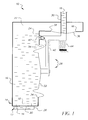
ink delivery apparatus 10 includes a closed ink reservoir orink accumulating chamber 14 fixed atop theprinthead 12. Anink 16 in thereservoir 14 is intended to drain in very small quantities first through afilter 18 and then through abottom slot 20, and into theprinthead 12. A slight-vacuum airspace 22, i.e. one that is slightly below atmospheric pressure, exists above theink level 24 in thereservoir 14. This is consistent with the known need to deliver theink 16 to theprinthead 12 at a slight negative pressure known as a "back pressure". Typically, as stated in prior U.S. Patent No. 5,650,811 issued July 22, 1997, the slight negative pressure in thereservoir 14 and theprinthead 12 may be approximately two to three inches of water below atmospheric pressure. The slight negative pressure is desired because it prevents theink 16 from leaking, i.e. drooling, out of closely spaced ink discharge nozzles (not shown in FIGS. 1 and 2) in anozzle plate 26 in theprinthead 12, by tending to draw the ink at the nozzles back into the printhead. Moreover, it forms a slightly concave ink meniscus at each nozzle which helps to keep the nozzle clean. - A pressure regulator and
ink replenishment mechanism 28 maintains the slight negative pressure in thereservoir 14 during delivery of theink 16 in very small quantities to theprinthead 12 from the reservoir, and in response to the ink delivery provides ink replenishment in similar quantities to the reservoir from a positive pressure ink supply source (not shown) that is in fluid communication with anink conduit 30 such as a tube which projects into the reservoir. See FIGS. 1 and 2. - The pressure regulator and
ink replenishment mechanism 28 includes a pressure regulator membrane ordiaphragm 32 that air-tightly covers a wall opening 34 in thereservoir 14. Thepressure regulator membrane 32 is compliant in order to maintain the slight negative pressure in thereservoir 14 by deforming inwardly at the wall opening 34 as shown in FIG. 2, to decrease the holding volume of the reservoir, during ink delivery from the reservoir to theprinthead 12, and by returning outwardly at the wall opening as shown in FIG. 1 to increase the holding volume of the reservoir, during ink replenishment to the reservoir via theink conduit 30. Also, themechanism 28 includes a valve membrane ordiaphragm 36, much smaller than thepressure regulator membrane 32, that air-tightly covers anotheropening 38 in thereservoir 14 and normally caps or closes theink conduit 30 to prevent ink replenishment to the reservoir. See FIG. 1. Thevalve member 36 is compliant to be deformed outwardly at theother opening 38 and away from theink conduit 30 to uncap or open the ink conduit as shown in FIG. 2, in order to initiate ink replenishment to thereservoir 14, and to return inwardly towards the ink conduit to recap the ink conduit as shown in FIG. 1, in order to terminate ink replenishment to the reservoir. - A
rocker lever 40, located outside thereservoir 14 to avoid being exposed to theink 16, is pivotally mounted via apivot pin 42 on the reservoir and intereconnects thepressure regulator membrane 32 and thevalve membrane 36. Ink delivery from thereservoir 14 to theprinthead 12 causes thepressure regulator membrane 32 to deform inwardly to decrease the holding volume of the reservoir as shown in FIG. 2, in turn to simultaneously forward (clockwise)-pivot therocker lever 40 to deform thevalve membrane 36 outwardly to uncap theink conduit 30 in order to initiate ink replenishment to the reservoir. When theink 16 is replenished to thereservoir 14, thepressure regulator membrane 32 returns outwardly to increase the holding volume of the reservoir as shown in FIG. 1, in turn to reverse (counterclockwise)-pivot therocker lever 40 to return thevalve membrane 36 outwardly to recap theink conduit 30 in order to terminate ink replenishment to the reservoir. - A
helical compression spring 44 applies a counterclockwise pivoting force in FIG. 1 to therocker lever 40 that causes the rocker lever to lightly hold thevalve membrane 36 capping theink conduit 30. The pivoting force is light enough to be readily overcome when thepressure regulator membrane 32 deforms inwardly as shown in FIG. 2. - FIG. 3 shows the
printhead 12, including closely spacednozzles 46 in thenozzle plate 26 andrespective firing chambers 48 for the nozzles. Eachfiring chamber 48 has a known thermal orpiezoelectric activator 50 which when activated by an electrical printing pulse causes a printing ink droplet to be ejected from the nozzle and onto a printing medium (not shown). - A method of cleaning the
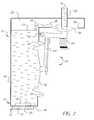
nozzles 46 using theink 16 is shown in FIGS. 4 and 5. FIGS. 4 and 5 depict theink delivery apparatus 10 partially modified to illustrate the nozzle cleaning method according to a preferred embodiment of the invention. - In FIG. 4, a
solenoid 52 or other known mechanical actuator is energized to move aplunger 54 of the solenoid to the left. Theplunger 54 then forward-pivots the rocker lever 40 about thepivot pin 42 to deform the compliantpressure regulator membrane 32 that covers the wall opening 34 in theink reservoir 14, inwardly at the wall opening, to decrease the ink holding volume of the reservoir. Also, thecompliant valve membrane 36 that covers theother opening 38 in the ink reservoir and caps theink conduit 30 projecting into the reservoir, is deformed outwardly at the other opening and away from the ink conduit, to uncap the ink conduit in order that the ink conduit can provide ink delivery at a positive pressure into the reservoir and out through thenozzles 46 to clean the nozzles. - After a sufficient time has elapsed for nozzle cleaning, as may be determined by a timer (not shown) for example, the
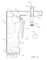
solenoid 52 is de-energized to retract theplunger 54 to the right in FIG. 5, to separate the plunger from therocker lever 40. Thespring 44 then reverse-pivots the rocker lever 40 about thepivot pin 42 to return thecompliant valve membrane 36 inwardly towards theink conduit 30 to recap the ink conduit in order to terminate ink delivery into thereservoir 14. Also, the compliantpressure regulator membrane 32 is deformed outwardly to increase the ink holding volume of thereservoir 14 in order to reduce ink pressure in the reservoir. - When the
valve membrane 36 has returned inwardly to recap theink conduit 30, but not before thepressure regulator membrane 32 has returned outwardly to increase the holding volume of thereservoir 14, the thermal orpiezoelectric activators 50 are activated numerous times, e.g. 2000 times, to cause very small quantities of theink 16 to be ejected from thenozzles 46. This ensures that a slight negative pressure is created in thereservoir 14 to prevents ink drool from thenozzles 46. However, this step is not necessarily a mandatory one since the step of deforming the compliantpressure regulator membrane 32 outwardly to increase the ink holding volume of thereservoir 14 may be sufficient to effect a slight negative pressure in thereservoir 14. - The
solenoid 52 with theplunger 54 may be wheeled away from theink delivery apparatus 10 during its operation as shown in FIGS. 1 and 2.
Claims (6)
- A method of cleaning spaced nozzles in a printhead of a drop-on-demand inkjet printer in which a slight negative pressure is desired in an ink reservoir in order to prevent ink drool from the nozzles, said method comprising:deforming a compliant pressure regulator membrane that covers an opening in an ink reservoir, inwardly at the opening, to decrease the ink holding volume of the reservoir;deforming a compliant valve membrane that covers an opening in the ink reservoir and caps an ink conduit projecting into the reservoir, outwardly at the opening and away from the ink conduit, to uncap the ink conduit in order that the ink conduit can provide ink delivery at a positive pressure into the reservoir and out through the nozzles to clean the nozzles;returning the compliant valve membrane inwardly towards the ink conduit to recap the ink conduit in order to terminate ink delivery into the reservoir; andreturning the compliant pressure regulator membrane outwardly to increase the ink holding volume of the reservoir in order to reduce ink pressure in the reservoir.
- A method as recited in claim 1, further comprising:ejecting some ink from the nozzles by activating thermal or piezoelectric activators for the nozzles, when the compliant valve membrane has returned inwardly to recap the ink conduit, and not before the compliant pressure regulator membrane has returned outwardly to increase the ink holding volume of the reservoir, in order to ensure a slight negative pressure in the reservoir which prevents ink drool from the nozzles.
- A method as recited in claim 1, further comprising:forward-pivoting a rocker lever interconnecting the compliant valve membrane and the compliant pressure regulator membrane to deform the compliant pressure regulator membrane inwardly to decrease the ink holding volume of the reservoir and deform the compliant valve membrane outwardly to uncap the ink conduit.
- A method as recited in claim 3, wherein the rocker lever is reverse-pivoted to return the compliant pressure regulator membrane outwardly to increase the ink holding volume of the reservoir and return the compliant valve membrane inwardly to recap the ink conduit.
- A method of cleaning spaced nozzles in a printhead of a drop-on-demand inkjet printer in which a slight negative pressure is desired in an ink reservoir in order to prevent ink drool from the nozzles, said method comprising:deforming a compliant pressure regulator membrane that covers a wall opening in an ink reservoir, inwardly at the wall opening, to decrease the ink holding volume of the reservoir, and deforming a compliant valve membrane that covers another opening in the ink reservoir and caps an ink conduit projecting into the reservoir, outwardly at the other opening and away from the ink conduit, to uncap the ink conduit in order that the ink conduit can provide ink delivery at a positive pressure into the reservoir and out through the nozzles to clean the nozzles, by forward-moving a connection member interconnecting the compliant valve membrane and the compliant pressure regulator membrane;returning the compliant valve membrane inwardly towards the ink conduit to recap the ink conduit in order to terminate ink delivery into the reservoir, and returning the compliant pressure regulator membrane outwardly to increase the ink holding volume of the reservoir in order to reduce ink pressure in the reservoir, by reverse-moving the connection member; andejecting some ink from the nozzles in order to ensure a slight negative pressure in the reservoir which prevents ink drool from the nozzles.
- A method as recited in claim 5, wherein some ink is ejected from the nozzles in order to ensure a slight negative pressure in the reservoir by activating a thermal or piezoelectric activators for the nozzles.
Applications Claiming Priority (2)
| Application Number | Priority Date | Filing Date | Title |
|---|---|---|---|
| US376560 | 2003-02-28 | ||
| US10/376,560 US6789874B1 (en) | 2003-02-28 | 2003-02-28 | Method of cleaning nozzles in inkjet printhead |
Publications (3)
| Publication Number | Publication Date |
|---|---|
| EP1452320A2 true EP1452320A2 (en) | 2004-09-01 |
| EP1452320A3 EP1452320A3 (en) | 2005-06-01 |
| EP1452320B1 EP1452320B1 (en) | 2012-01-11 |
Family
ID=32771499
Family Applications (1)
| Application Number | Title | Priority Date | Filing Date |
|---|---|---|---|
| EP04075469A Expired - Fee Related EP1452320B1 (en) | 2003-02-28 | 2004-02-16 | Method of cleaning nozzles in inkjet printhead |
Country Status (3)
| Country | Link |
|---|---|
| US (1) | US6789874B1 (en) |
| EP (1) | EP1452320B1 (en) |
| JP (1) | JP2004262245A (en) |
Cited By (4)
| Publication number | Priority date | Publication date | Assignee | Title |
|---|---|---|---|---|
| WO2007050173A1 (en) * | 2005-10-28 | 2007-05-03 | Hewlett-Packard Development Company, L.P. | Free flow fluid delivery system for printing device |
| EP1995070A2 (en) * | 2007-05-09 | 2008-11-26 | BARBERAN LATORRE, Jesus Francisco | Ink supply system for printers |
| EP2952352A1 (en) * | 2014-03-28 | 2015-12-09 | Seiko Epson Corporation | Liquid ejecting head, liquid ejecting apparatus, flow passage member, and method of controlling liquid ejecting head |
| EP4279280A1 (en) * | 2022-05-18 | 2023-11-22 | Canon Kabushiki Kaisha | Liquid ejection head |
Families Citing this family (8)
| Publication number | Priority date | Publication date | Assignee | Title |
|---|---|---|---|---|
| US7597417B2 (en) * | 2004-03-08 | 2009-10-06 | Fujifilm Corporation | Discharge determination device and method |
| JP4874605B2 (en) * | 2005-09-12 | 2012-02-15 | 株式会社リコー | Ink supply container, recording apparatus, and ink supply method |
| US20110205318A1 (en) * | 2010-02-24 | 2011-08-25 | Price Brian G | Ink tank check valve for pressure regulation |
| US20110205268A1 (en) * | 2010-02-24 | 2011-08-25 | Price Brian G | Method for ink tank pressure regulation |
| JP5488314B2 (en) * | 2010-08-03 | 2014-05-14 | 株式会社リコー | Image forming apparatus |
| WO2012023424A1 (en) * | 2010-08-17 | 2012-02-23 | コニカミノルタオプト株式会社 | Method of manufacturing light-emitting device |
| WO2018147870A1 (en) | 2017-02-10 | 2018-08-16 | Hewlett-Packard Development Company, L.P. | Fluid cartridge |
| WO2020036589A1 (en) * | 2018-08-14 | 2020-02-20 | Hewlett-Packard Development Company, L.P. | Inhibiting media deformation |
Citations (2)
| Publication number | Priority date | Publication date | Assignee | Title |
|---|---|---|---|---|
| US4509062A (en) | 1982-11-23 | 1985-04-02 | Hewlett-Packard Company | Ink reservoir with essentially constant negative back pressure |
| US6084617A (en) | 1995-10-31 | 2000-07-04 | Hewlett-Packard Company | Narrow body inkjet print cartridge having parallel configuration of internal components |
Family Cites Families (10)
| Publication number | Priority date | Publication date | Assignee | Title |
|---|---|---|---|---|
| JP3180401B2 (en) * | 1991-12-24 | 2001-06-25 | セイコーエプソン株式会社 | Ink ejection recovery device for inkjet printer |
| US5650811A (en) | 1993-05-21 | 1997-07-22 | Hewlett-Packard Company | Apparatus for providing ink to a printhead |
| US5736992A (en) * | 1994-10-31 | 1998-04-07 | Hewlett-Packard | Pressure regulated free-ink ink-jet pen |
| JP3528322B2 (en) * | 1995-05-19 | 2004-05-17 | ブラザー工業株式会社 | Ink jet recording device |
| US6257714B1 (en) * | 1995-10-27 | 2001-07-10 | Hewlett-Packard Company | Method and apparatus for removing air from an inkjet print cartridge |
| DE69716772T2 (en) * | 1996-12-24 | 2003-07-03 | Seiko Epson Corp | Ink jet recording apparatus |
| US6315468B2 (en) * | 1997-01-30 | 2001-11-13 | Seiko Epson Corporation | Ink jet recording apparatus with a platen gap regulator |
| US6224188B1 (en) * | 1998-12-14 | 2001-05-01 | Seiko Epson Corporation | Ink-jet recording apparatus |
| EP1147901B1 (en) * | 2000-04-18 | 2005-10-19 | Seiko Epson Corporation | Ink-jet recording device |
| US6908180B2 (en) * | 2003-02-24 | 2005-06-21 | Eastman Kodak Company | Ink delivery apparatus for inkjet printhead |
-
2003
- 2003-02-28 US US10/376,560 patent/US6789874B1/en not_active Expired - Fee Related
-
2004
- 2004-02-16 EP EP04075469A patent/EP1452320B1/en not_active Expired - Fee Related
- 2004-02-26 JP JP2004052177A patent/JP2004262245A/en active Pending
Patent Citations (2)
| Publication number | Priority date | Publication date | Assignee | Title |
|---|---|---|---|---|
| US4509062A (en) | 1982-11-23 | 1985-04-02 | Hewlett-Packard Company | Ink reservoir with essentially constant negative back pressure |
| US6084617A (en) | 1995-10-31 | 2000-07-04 | Hewlett-Packard Company | Narrow body inkjet print cartridge having parallel configuration of internal components |
Cited By (8)
| Publication number | Priority date | Publication date | Assignee | Title |
|---|---|---|---|---|
| WO2007050173A1 (en) * | 2005-10-28 | 2007-05-03 | Hewlett-Packard Development Company, L.P. | Free flow fluid delivery system for printing device |
| US7568793B2 (en) | 2005-10-28 | 2009-08-04 | Hewlett-Packard Development Company, L.P. | Printing fluid control in printing device |
| EP1995070A2 (en) * | 2007-05-09 | 2008-11-26 | BARBERAN LATORRE, Jesus Francisco | Ink supply system for printers |
| EP1995070A3 (en) * | 2007-05-09 | 2009-09-16 | BARBERAN LATORRE, Jesus Francisco | Ink supply system for printers |
| EP2952352A1 (en) * | 2014-03-28 | 2015-12-09 | Seiko Epson Corporation | Liquid ejecting head, liquid ejecting apparatus, flow passage member, and method of controlling liquid ejecting head |
| US9358802B2 (en) | 2014-03-28 | 2016-06-07 | Seiko Epson Corporation | Liquid ejecting head, liquid ejecting apparatus, flow passage member, and method of controlling liquid ejecting head |
| US9994038B2 (en) | 2014-03-28 | 2018-06-12 | Seiko Epson Corporation | Liquid ejecting head, liquid ejecting apparatus, flow passage member, and method of controlling liquid ejecting head |
| EP4279280A1 (en) * | 2022-05-18 | 2023-11-22 | Canon Kabushiki Kaisha | Liquid ejection head |
Also Published As
| Publication number | Publication date |
|---|---|
| EP1452320B1 (en) | 2012-01-11 |
| US6789874B1 (en) | 2004-09-14 |
| US20040169696A1 (en) | 2004-09-02 |
| JP2004262245A (en) | 2004-09-24 |
| EP1452320A3 (en) | 2005-06-01 |
Similar Documents
| Publication | Publication Date | Title |
|---|---|---|
| EP1621352B1 (en) | Fluid delivery techniques with improved reliability | |
| JP5163286B2 (en) | Liquid ejection apparatus and image projection apparatus | |
| US7762656B2 (en) | Method for preventing nozzle contamination during warm-up | |
| US7992986B2 (en) | Method for increasing printhead reliability | |
| JP4885879B2 (en) | Fluid drop discharge | |
| US8596746B2 (en) | Inkjet pen/printhead with shipping fluid | |
| KR970007636B1 (en) | Ink-jet apparatus capable of practicing an improved recovery operation | |
| EP1464500B1 (en) | An ink jet head cleaning method and an ink jet recording apparatus | |
| EP1452320B1 (en) | Method of cleaning nozzles in inkjet printhead | |
| CN108177441B (en) | Liquid ejecting apparatus | |
| EP1449665A1 (en) | Ink delivery apparatus for inkjet printhead | |
| US20100245465A1 (en) | Liquid supplying apparatus and liquid ejecting apparatus | |
| US20100020126A1 (en) | Liquid supply device and liquid ejecting apparatus | |
| JP2004025531A (en) | Maintenance method and maintenance fitment of inkjet head | |
| JPH11179932A (en) | Image forming method and apparatus therefor | |
| JP2003266734A (en) | Ink jet recorder and method for supplying ink | |
| JP2007223266A (en) | Liquid injection device and its cleaning method | |
| JPH06191049A (en) | Ink tank, ink jet cartridge, ink jet recording apparatus and device and method for injecting ink into ink tank | |
| JP2010120249A (en) | Recorder | |
| JP2003089217A (en) | Ink supply device and ink jet recorder | |
| JP2001071536A (en) | Ink jet recording apparatus | |
| JP2006181921A (en) | Liquid-ejecting apparatus and liquid-suction device for liquid-ejecting apparatus | |
| JP2019072929A (en) | Liquid jet device and maintenance method of the liquid jet device | |
| JPH08310005A (en) | Ink-jet printer | |
| JP2001096765A (en) | Ink jet recording apparatus and cleaning control method therefor |
Legal Events
| Date | Code | Title | Description |
|---|---|---|---|
| PUAI | Public reference made under article 153(3) epc to a published international application that has entered the european phase |
Free format text: ORIGINAL CODE: 0009012 |
|
| AK | Designated contracting states |
Kind code of ref document: A2 Designated state(s): AT BE BG CH CY CZ DE DK EE ES FI FR GB GR HU IE IT LI LU MC NL PT RO SE SI SK TR |
|
| AX | Request for extension of the european patent |
Extension state: AL LT LV MK |
|
| PUAL | Search report despatched |
Free format text: ORIGINAL CODE: 0009013 |
|
| AK | Designated contracting states |
Kind code of ref document: A3 Designated state(s): AT BE BG CH CY CZ DE DK EE ES FI FR GB GR HU IE IT LI LU MC NL PT RO SE SI SK TR |
|
| AX | Request for extension of the european patent |
Extension state: AL LT LV MK |
|
| 17P | Request for examination filed |
Effective date: 20051021 |
|
| AKX | Designation fees paid |
Designated state(s): DE FR GB |
|
| 17Q | First examination report despatched |
Effective date: 20100129 |
|
| GRAP | Despatch of communication of intention to grant a patent |
Free format text: ORIGINAL CODE: EPIDOSNIGR1 |
|
| GRAS | Grant fee paid |
Free format text: ORIGINAL CODE: EPIDOSNIGR3 |
|
| GRAA | (expected) grant |
Free format text: ORIGINAL CODE: 0009210 |
|
| AK | Designated contracting states |
Kind code of ref document: B1 Designated state(s): DE FR GB |
|
| REG | Reference to a national code |
Ref country code: GB Ref legal event code: FG4D |
|
| REG | Reference to a national code |
Ref country code: DE Ref legal event code: R096 Ref document number: 602004036056 Country of ref document: DE Effective date: 20120315 |
|
| PLBE | No opposition filed within time limit |
Free format text: ORIGINAL CODE: 0009261 |
|
| STAA | Information on the status of an ep patent application or granted ep patent |
Free format text: STATUS: NO OPPOSITION FILED WITHIN TIME LIMIT |
|
| 26N | No opposition filed |
Effective date: 20121012 |
|
| REG | Reference to a national code |
Ref country code: DE Ref legal event code: R097 Ref document number: 602004036056 Country of ref document: DE Effective date: 20121012 |
|
| PGFP | Annual fee paid to national office [announced via postgrant information from national office to epo] |
Ref country code: FR Payment date: 20130218 Year of fee payment: 10 Ref country code: GB Payment date: 20130125 Year of fee payment: 10 |
|
| PGFP | Annual fee paid to national office [announced via postgrant information from national office to epo] |
Ref country code: DE Payment date: 20140228 Year of fee payment: 11 |
|
| GBPC | Gb: european patent ceased through non-payment of renewal fee |
Effective date: 20140216 |
|
| REG | Reference to a national code |
Ref country code: FR Ref legal event code: ST Effective date: 20141031 |
|
| PG25 | Lapsed in a contracting state [announced via postgrant information from national office to epo] |
Ref country code: GB Free format text: LAPSE BECAUSE OF NON-PAYMENT OF DUE FEES Effective date: 20140216 Ref country code: FR Free format text: LAPSE BECAUSE OF NON-PAYMENT OF DUE FEES Effective date: 20140228 |
|
| REG | Reference to a national code |
Ref country code: DE Ref legal event code: R119 Ref document number: 602004036056 Country of ref document: DE |
|
| PG25 | Lapsed in a contracting state [announced via postgrant information from national office to epo] |
Ref country code: DE Free format text: LAPSE BECAUSE OF NON-PAYMENT OF DUE FEES Effective date: 20150901 |