EP1454752A1 - Ink container - Google Patents
Ink container Download PDFInfo
- Publication number
- EP1454752A1 EP1454752A1 EP04003060A EP04003060A EP1454752A1 EP 1454752 A1 EP1454752 A1 EP 1454752A1 EP 04003060 A EP04003060 A EP 04003060A EP 04003060 A EP04003060 A EP 04003060A EP 1454752 A1 EP1454752 A1 EP 1454752A1
- Authority
- EP
- European Patent Office
- Prior art keywords
- ink container
- container body
- storage means
- ink
- bonded
- Prior art date
- Legal status (The legal status is an assumption and is not a legal conclusion. Google has not performed a legal analysis and makes no representation as to the accuracy of the status listed.)
- Granted
Links
- 239000000853 adhesive Substances 0.000 claims description 9
- 230000001070 adhesive effect Effects 0.000 claims description 9
- 238000000034 method Methods 0.000 description 3
- 238000012986 modification Methods 0.000 description 3
- 230000004048 modification Effects 0.000 description 3
- 239000011347 resin Substances 0.000 description 3
- 229920005989 resin Polymers 0.000 description 3
- 238000000926 separation method Methods 0.000 description 3
- 239000003522 acrylic cement Substances 0.000 description 2
- 238000002474 experimental method Methods 0.000 description 2
- 239000004743 Polypropylene Substances 0.000 description 1
- 238000004891 communication Methods 0.000 description 1
- 230000007613 environmental effect Effects 0.000 description 1
- 238000011156 evaluation Methods 0.000 description 1
- 239000000463 material Substances 0.000 description 1
- -1 polypropylene Polymers 0.000 description 1
- 229920001155 polypropylene Polymers 0.000 description 1
- 229920003002 synthetic resin Polymers 0.000 description 1
- 239000000057 synthetic resin Substances 0.000 description 1
Images


Classifications
-
- B—PERFORMING OPERATIONS; TRANSPORTING
- B41—PRINTING; LINING MACHINES; TYPEWRITERS; STAMPS
- B41J—TYPEWRITERS; SELECTIVE PRINTING MECHANISMS, i.e. MECHANISMS PRINTING OTHERWISE THAN FROM A FORME; CORRECTION OF TYPOGRAPHICAL ERRORS
- B41J2/00—Typewriters or selective printing mechanisms characterised by the printing or marking process for which they are designed
- B41J2/005—Typewriters or selective printing mechanisms characterised by the printing or marking process for which they are designed characterised by bringing liquid or particles selectively into contact with a printing material
- B41J2/01—Ink jet
- B41J2/17—Ink jet characterised by ink handling
- B41J2/175—Ink supply systems ; Circuit parts therefor
- B41J2/17503—Ink cartridges
- B41J2/17559—Cartridge manufacturing
-
- B—PERFORMING OPERATIONS; TRANSPORTING
- B41—PRINTING; LINING MACHINES; TYPEWRITERS; STAMPS
- B41J—TYPEWRITERS; SELECTIVE PRINTING MECHANISMS, i.e. MECHANISMS PRINTING OTHERWISE THAN FROM A FORME; CORRECTION OF TYPOGRAPHICAL ERRORS
- B41J2/00—Typewriters or selective printing mechanisms characterised by the printing or marking process for which they are designed
- B41J2/005—Typewriters or selective printing mechanisms characterised by the printing or marking process for which they are designed characterised by bringing liquid or particles selectively into contact with a printing material
- B41J2/01—Ink jet
- B41J2/015—Ink jet characterised by the jet generation process
- B41J2/04—Ink jet characterised by the jet generation process generating single droplets or particles on demand
- B41J2/045—Ink jet characterised by the jet generation process generating single droplets or particles on demand by pressure, e.g. electromechanical transducers
- B41J2/04501—Control methods or devices therefor, e.g. driver circuits, control circuits
- B41J2/04536—Control methods or devices therefor, e.g. driver circuits, control circuits using history data
-
- B—PERFORMING OPERATIONS; TRANSPORTING
- B41—PRINTING; LINING MACHINES; TYPEWRITERS; STAMPS
- B41J—TYPEWRITERS; SELECTIVE PRINTING MECHANISMS, i.e. MECHANISMS PRINTING OTHERWISE THAN FROM A FORME; CORRECTION OF TYPOGRAPHICAL ERRORS
- B41J2/00—Typewriters or selective printing mechanisms characterised by the printing or marking process for which they are designed
- B41J2/005—Typewriters or selective printing mechanisms characterised by the printing or marking process for which they are designed characterised by bringing liquid or particles selectively into contact with a printing material
- B41J2/01—Ink jet
- B41J2/17—Ink jet characterised by ink handling
- B41J2/175—Ink supply systems ; Circuit parts therefor
- B41J2/17503—Ink cartridges
- B41J2/1752—Mounting within the printer
-
- B—PERFORMING OPERATIONS; TRANSPORTING
- B41—PRINTING; LINING MACHINES; TYPEWRITERS; STAMPS
- B41J—TYPEWRITERS; SELECTIVE PRINTING MECHANISMS, i.e. MECHANISMS PRINTING OTHERWISE THAN FROM A FORME; CORRECTION OF TYPOGRAPHICAL ERRORS
- B41J2/00—Typewriters or selective printing mechanisms characterised by the printing or marking process for which they are designed
- B41J2/005—Typewriters or selective printing mechanisms characterised by the printing or marking process for which they are designed characterised by bringing liquid or particles selectively into contact with a printing material
- B41J2/01—Ink jet
- B41J2/17—Ink jet characterised by ink handling
- B41J2/175—Ink supply systems ; Circuit parts therefor
- B41J2/17503—Ink cartridges
- B41J2/17543—Cartridge presence detection or type identification
- B41J2/17546—Cartridge presence detection or type identification electronically
-
- B—PERFORMING OPERATIONS; TRANSPORTING
- B41—PRINTING; LINING MACHINES; TYPEWRITERS; STAMPS
- B41J—TYPEWRITERS; SELECTIVE PRINTING MECHANISMS, i.e. MECHANISMS PRINTING OTHERWISE THAN FROM A FORME; CORRECTION OF TYPOGRAPHICAL ERRORS
- B41J2/00—Typewriters or selective printing mechanisms characterised by the printing or marking process for which they are designed
- B41J2/005—Typewriters or selective printing mechanisms characterised by the printing or marking process for which they are designed characterised by bringing liquid or particles selectively into contact with a printing material
- B41J2/01—Ink jet
- B41J2/17—Ink jet characterised by ink handling
- B41J2/175—Ink supply systems ; Circuit parts therefor
- B41J2/17503—Ink cartridges
- B41J2/17553—Outer structure
Definitions
- This invention relates to an ink container with a storage means for storing predetermined information.
- the ink container disclosed in Japanese Unexamined Patent Publication No. 10(1998)-133529 is disadvantageous in that since the storage means is embedded in the ink container body, it is difficult to separate the storage means from the ink container body when the empty ink containers are discarded or recycled.
- the ink container disclosed in U.S. Patent No. 6,530,519 is provided with a circuit board which carries a memory IC and directly bonded to the ink container body. Also, in this ink container, it is difficult to separate the memory IC from the ink container body and separation of the memory IC by force can result in damage on the memory IC depending on the state of bonding of the circuit board to the ink container body.
- the primary object of the present invention is to provide an ink container with a storage means for storing predetermined information in which the storage means can be easily removed from the ink container body after ink accommodated therein is consumed.
- an ink container comprising an ink container body and a storage means attached to the ink container body for storing predetermined information, wherein the storage means is bonded to a part of the surface of the ink container body at its surface opposed to the surface of the ink container body over an area not larger than 90% of its surface facing toward said part of the surface of the ink container body.
- the “storage means” may be any storage means so long as information stored therein is readable or readable and writable from external devices.
- the storage means be bonded to the part of the surface of the ink container body by an adhesive, the adhesion of the adhesive be 20N/25mm and at the same time, the storage means be bonded to a part of the surface of the ink container body at its surface opposed to the surface of the ink container body over an area not smaller than 30% and not larger than 90% of its surface facing toward said part of the surface of the ink container body.
- a part or the whole of outer periphery of said surface of the storage means facing toward the part of the surface of the ink container body is preferably not bonded to the surface of the ink container body.
- an ink container comprising an ink container body and a storage means attached to the ink container body for storing predetermined information, wherein the storage means is bonded to a surface of the ink container body at its surface opposed to the surface of the ink container body by way of a protrusion means which is smaller in area than a surface of the storage means facing toward the part of the surface of the ink container body.
- the protrusion means may be formed either integrally with said storage means or the ink container body or as a member separate from said storage means and the ink container body.
- the protrusion means may comprise a plurality of ribs formed at predetermined spaces from each other.
- the ribs are rounded at least one of the end portions respectively in contact with the ink container body and the storage means.
- the protrusion means may comprise a plurality of projections which are brought into contact with the ink container body or the storage means at a point.
- the projections are rounded at least one of the end portions respectively in contact with the ink container body and the storage means.
- the protrusion means is absent in positions opposed to a part or the whole of outer periphery of said surface of the storage means facing toward the part of the surface of the ink container body.
- each of the projections are rounded at least one of the end portions means that at least one of the end portions of each of the ribs has a rounded cross-section, and that the projections are rounded at least one of the end portions means that at least one of the opposite end portions of each of the projections is, for instance, semispherical.
- each of the projections may be spherical as a whole. That is, the end portion may be of any shape so long as the end portion is partly rounded.
- an ink container comprising an ink container body and a storage means attached to the ink container body for storing predetermined information, wherein the storage means is mounted on the ink container body by way of a mounting member which is removably mounted on the ink container body.
- the storage means In the ink container in accordance with the first aspect of the present invention where the storage means is bonded to a part of the surface of the ink container body at its surface opposed to the surface of the ink container body over an area not larger than 90% of its surface facing toward said part of the surface of the ink container body, the storage means can be easily removed from the ink container body and easily separated therefrom after ink accommodated therein is consumed.
- the adhesion of the adhesive is 20N/25mm and at the same time, the storage means is bonded to a part of the surface of the ink container body at its surface opposed to the surface of the ink container body over an area not smaller than 30% and not larger than 90% of its surface facing toward said part of the surface of the ink container body, damage on the storage means upon separation of the storage means from the ink container body can be prevented, and at the same time, inadvertent separation of the storage means from the ink container body on impact, which can result in communication trouble in a stencil printer or the like, can be prevented.
- the storage means can be removed from the ink container body by inserting a removal member from the outer periphery of the surface of the storage means which is not bonded to the surface of the ink container body and accordingly the storage means can be more easily removed from the ink container body.
- the storage means In the ink container in accordance with the second aspect of the present invention where the storage means is bonded to a surface of the ink container body at its surface opposed to the surface of the ink container body by way of a protrusion means which is smaller in area than a surface of the storage means facing toward the part of the surface of the ink container body, the storage means can be easily removed from the ink container body and easily separated therefrom after ink accommodated therein is consumed as in the ink container in accordance with the first aspect.
- the protrusion means comprises a plurality of ribs formed at predetermined spaces from each other or a plurality of projections which are brought into contact with the ink container body or the storage means at a point
- the storage means can be stably held in place and at the same time, the storage means can be easily removed from the ink container body after ink accommodated therein is consumed.
- the storage means can be removed from the ink container body by inserting a removal member from the outer periphery of the surface of the storage means which is not bonded to the surface of the ink container body and accordingly the storage means can be more easily removed from the ink container body.
- the storage means can be further easily removed from the ink container body.
- the storage means In the ink container in accordance with the third aspect of the present invention where the storage means is mounted on the ink container body by way of a mounting member which is removably mounted on the ink container body, the storage means can be easily removed from the ink container body and easily separated therefrom after ink accommodated therein is consumed as in the ink containers in accordance with the first and second aspects of the present invention.
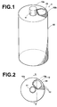
- an ink container 1 comprises an ink container body 10 which is formed of synthetic resin and is substantially cylindrical in shape and a storage means 20 for storing predetermined information.
- An ink discharge port 11 through which ink in the ink container body 10 is discharged is provided on an upper end face 10a of the ink container body 10.
- a memory site 10b where the storage means 20 is provided is formed on a part of the upper end face 10a of the ink container body 10.
- a base sheet on which a memory IC is mounted, that on which a bar code is recorded or that on which characters or symbols are recorded may be employed.
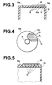
- Figure 2 is a plan view of the ink container 1 and Figure 3 is a cross-sectional view taken along line 3-3 in Figure 2.
- the memory site 10b is formed on a part of the upper end face 10a. That is, a recess is formed in the upper end face 10a, and the storage means 20 are bonded to ribs 12 formed on the bottom surface of the recess as shown in Figure 3.
- the storage means 20 can be easily removed from the ink container body 10 and easily separated therefrom after ink accommodated therein is consumed since the storage means 20 is bonded to the ink container body 10 by way of the ribs 12 formed in the memory site 10b.
- Forming the ribs 12 in this manner is advantageous in that the storage means 20 can be removed from the ink container body 10 by inserting a removal member from the outer periphery of the surface of the storage means 20 which is not bonded to the surface of the ink container body 10 and accordingly the storage means 20 can be more easily removed from the ink container body 10. Further when the ribs 12 are formed so that they extend in the direction of arrow A in which the removal member is inserted as shown in Figure 4, the storage means 20 can be more easily removed from the ink container body 10 as compared with when the ribs 12 are formed so that they extend, for instance, in perpendicular to the direction of arrow A.
- each rib 12 in contact with the memory means 20 may be rounded as shown in Figure 5.
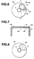
- the memory means 20 may be bonded to the ink container body 10 by way of a plurality of spot projections 13 formed in the memory site 10b in place of the ribs 12 (12a) as shown in Figure 8.
- the end portion of each spot projection 13 in contact with the memory means 20 may be also rounded. Also in this case, no spot projection 13 may be formed in positions opposed to a part of the outer periphery of the storage means 20 as shown in Figure 8.
- the storage means 20 may be directly bonded to the memory site 10b, for instance, by adhesive without forming a protrusion means (e.g., the ribs 12 (12a) or the spot projections 13). However, in this case, the storage means 20 is bonded to the memory site 10b of the ink container body 10 over an area not larger than 90% of its surface 20a ( Figure 3) facing toward the memory site 10b.
- a protrusion means e.g., the ribs 12 (12a) or the spot projections 13.
- the storage means 20 is bonded to the memory site 10b of the ink container body 10 over an area not larger than 90% of its surface 20a ( Figure 3) facing toward the memory site 10b.
- the storage means 20 is directly bonded to the memory site 10b by adhesive, it is preferred that a part or the whole of outer periphery of the storage means 20 facing toward the memory site 10b of the ink container body 10 be not bonded to the surface of the memory site 10b.
- the bond strengths were measured with the bonding area set to 20% to 100% of the surface 20a of the storage means 20 facing toward the ink container body 10.
- the bond strengths were measured by the use of a SHIMADZU AGS500D (with the load cell for 50N) with the storage means 20 peeled off the ink container body 10 from a state horizontally bonded to the ink container body 10 (a so-called 180 1 peeling).
- the rate of pulling was 300mm/min and the environmental temperature and humidity were 23°C and 50%RH.
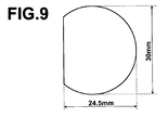
- the storage means 20 was as shown in Figure 9, and the bond strength means a maximum bond strength encountered when the storage means 20 was fully peeled off.
- the adhesion of the adhesive for bonding the storage means 20 to the container body 10 was 20N/25mm and the storage means 20 was bonded to the container body 10 by the use of an acrylic adhesive.
- the adhesion of the acrylic adhesive was that to polypropylene.
- the peeling easiness of the storage means 20 was evaluated for each bonding area on the basis of the measured bond strength and tabulated in the following table. bonding area (%) bond strength (N) evaluation 100 21.9 ⁇ 95 16.5 ⁇ 90 10.5 ⁇ 80 6.7 ⁇ 70 6.8 ⁇ 60 4.7 ⁇ 40 4.1 ⁇ 30 3.8 ⁇ 25 2.9 ⁇ 20 2.5 ⁇ ⁇ represents that the storage means is difficult to peel off or is readily peeled off. ⁇ represents that the storage means is easy to peel off and cannot be readily peeled off.
- the bonding area be not smaller than 30% and not larger than 90% of the surface of the storage means 20 facing toward the surface of the ink container body 10 in order to bond the storage means 20 to be easily peeled off the ink container body 10 and not to be readily peeled off the ink container body 10 on impact.
- the storage means 20 may be mounted on the ink container body 10 by way of a mounting member 30 which is removably mounted on the upper end face 10a of the ink container body 10 as shown in Figures 10A and 10B. That is, as shown in Figure 10A, a pair of grooves 14 and a projection 15 are formed in the upper surface 10a of the ink container body 10.
- the mounting member 30 comprises a resin plate 30a conforming to the upper end face 10a of the ink container body 10, and a pair of first fixing portions 30b which are respectively engaged with the grooves 14 and a second fixing portion 30c which is engaged with the projection 15 are formed in the resin plate 30a.
- the storage means 20 is carried by the resin plate 30a and is fixed to the upper end face 10a of the ink container body 10 by mounting the mounting member 30 on the upper end face 10a of the ink container body 10 with the first fixing portions 30b respectively engaged with the grooves 14 and the second fixing portion 30c engaged with the projection 15.
- the second fixing portion 30c is formed of material which is somewhat flexible to allow the second fixing portion 30c to be deformed to be engaged with the projection 15.
- the storage means 20 may be mounted on the ink container body 10 by way of a donut-like mounting member 40 shown in Figure 11. That is, the mounting member 40 comprises a donut-like disk and a rib 40b on the inner surface 40a of the disk.
- the storage means 20 is provided on the rib 40b and the mounting member 40 is removably mounted on the ink container body 10.
- Figure 12A is a view of the mounting member 40 as viewed in the direction of arrow B in Figure 11
- Figure 12B is a cross-sectional view taken along line b-b in Figure 12A of the mounting member 40 when the mounting member 40 is mounted on the ink container body 10 with the storage means 20 provided on the rib 40b.
- the mounting member 40 is provided with protrusions 40c and the mounting member 40 is removably mounted on the ink container body 10 by bringing the protrusions 40c into engagement with recesses formed on a part 16 of the ink container body 10.
- the mounting member 40 is removably mounted on the ink container body 10 by press fitting, the mounting member 40 may be removably mounted on the ink container body 10 by other various methods.
- the mounting member 40 may be removably mounted on the ink container body 10 by screwing.
- the shape of the mounting member need not be limited to the illustrated shape but the mounting member may be of any shape so long as it can be removably mounted on the ink container body 10.
- the memory site 10b is provided on an upper end face 10a of the ink container body 10a, the memory site 10b may be provided on any part of the ink container body 10.
- the ink container body 10 is substantially cylindrical in shape, the ink container body 10 may be of any shape.
Abstract
Description
- This invention relates to an ink container with a storage means for storing predetermined information.
- In the past, a removable ink container has been used in a stencil printer since it is easy to handle. When ink in the container has been consumed, the container is removed from the stencil printer to be discarded or recycled and a new ink container is mounted on the stencil printer. In such ink containers, there has been proposed, for instance, in Japanese Unexamined Patent Publication No. 10(1998)-133529, an ink container in which a storage means such as a memory IC is provided and the ink consumption and/or the dates of use in the stencil printer are stored. By reading out the ink consumption and/or the dates of use stored in the storage means, the state of use and or the like of the stencil printer can be known and used.
- In the method proposed in U.S. Patent No. 6,530,519, information on viscosity and/or color of ink accommodated in the ink container is stored in a memory IC and the stencil printer controls the press pressure during printing on the basis of the information on viscosity and/or color of ink accommodated in the ink container. Further, there has been proposed a method in which the remainder of ink in the container is stored in a memory IC and an alarm is given when the remainder of ink in the container is minimized.
- However, the ink container disclosed in Japanese Unexamined Patent Publication No. 10(1998)-133529 is disadvantageous in that since the storage means is embedded in the ink container body, it is difficult to separate the storage means from the ink container body when the empty ink containers are discarded or recycled. The ink container disclosed in U.S. Patent No. 6,530,519 is provided with a circuit board which carries a memory IC and directly bonded to the ink container body. Also, in this ink container, it is difficult to separate the memory IC from the ink container body and separation of the memory IC by force can result in damage on the memory IC depending on the state of bonding of the circuit board to the ink container body.
- In view of the foregoing observations and description, the primary object of the present invention is to provide an ink container with a storage means for storing predetermined information in which the storage means can be easily removed from the ink container body after ink accommodated therein is consumed.
- In accordance with a first aspect of the present invention, there is provided an ink container comprising an ink container body and a storage means attached to the ink container body for storing predetermined information, wherein the storage means is bonded to a part of the surface of the ink container body at its surface opposed to the surface of the ink container body over an area not larger than 90% of its surface facing toward said part of the surface of the ink container body.
- The "storage means" may be any storage means so long as information stored therein is readable or readable and writable from external devices.
- It is preferred that the storage means be bonded to the part of the surface of the ink container body by an adhesive, the adhesion of the adhesive be 20N/25mm and at the same time, the storage means be bonded to a part of the surface of the ink container body at its surface opposed to the surface of the ink container body over an area not smaller than 30% and not larger than 90% of its surface facing toward said part of the surface of the ink container body.
- Further, a part or the whole of outer periphery of said surface of the storage means facing toward the part of the surface of the ink container body is preferably not bonded to the surface of the ink container body.
- In accordance with a second aspect of the present invention, there is provided an ink container comprising an ink container body and a storage means attached to the ink container body for storing predetermined information, wherein the storage means is bonded to a surface of the ink container body at its surface opposed to the surface of the ink container body by way of a protrusion means which is smaller in area than a surface of the storage means facing toward the part of the surface of the ink container body.
- The protrusion means may be formed either integrally with said storage means or the ink container body or as a member separate from said storage means and the ink container body.
- For example, the protrusion means may comprise a plurality of ribs formed at predetermined spaces from each other.
- It is preferred that the ribs are rounded at least one of the end portions respectively in contact with the ink container body and the storage means.
- Otherwise, the protrusion means may comprise a plurality of projections which are brought into contact with the ink container body or the storage means at a point.
- It is preferred that the projections are rounded at least one of the end portions respectively in contact with the ink container body and the storage means.
- In one embodiment, the protrusion means is absent in positions opposed to a part or the whole of outer periphery of said surface of the storage means facing toward the part of the surface of the ink container body.
- That the ribs are rounded at least one of the end portions means that at least one of the end portions of each of the ribs has a rounded cross-section, and that the projections are rounded at least one of the end portions means that at least one of the opposite end portions of each of the projections is, for instance, semispherical. Or, each of the projections may be spherical as a whole. That is, the end portion may be of any shape so long as the end portion is partly rounded.
- In accordance with a third aspect of the present invention, there is provided an ink container comprising an ink container body and a storage means attached to the ink container body for storing predetermined information, wherein the storage means is mounted on the ink container body by way of a mounting member which is removably mounted on the ink container body.
- In the ink container in accordance with the first aspect of the present invention where the storage means is bonded to a part of the surface of the ink container body at its surface opposed to the surface of the ink container body over an area not larger than 90% of its surface facing toward said part of the surface of the ink container body, the storage means can be easily removed from the ink container body and easily separated therefrom after ink accommodated therein is consumed.
- When the storage means is bonded to the part of the surface of the ink container body by an adhesive, the adhesion of the adhesive is 20N/25mm and at the same time, the storage means is bonded to a part of the surface of the ink container body at its surface opposed to the surface of the ink container body over an area not smaller than 30% and not larger than 90% of its surface facing toward said part of the surface of the ink container body, damage on the storage means upon separation of the storage means from the ink container body can be prevented, and at the same time, inadvertent separation of the storage means from the ink container body on impact, which can result in communication trouble in a stencil printer or the like, can be prevented.
- When a part or the whole of outer periphery of said surface of the storage means facing toward the part of the surface of the ink container body is not bonded to the surface of the ink container body, the storage means can be removed from the ink container body by inserting a removal member from the outer periphery of the surface of the storage means which is not bonded to the surface of the ink container body and accordingly the storage means can be more easily removed from the ink container body.
- In the ink container in accordance with the second aspect of the present invention where the storage means is bonded to a surface of the ink container body at its surface opposed to the surface of the ink container body by way of a protrusion means which is smaller in area than a surface of the storage means facing toward the part of the surface of the ink container body, the storage means can be easily removed from the ink container body and easily separated therefrom after ink accommodated therein is consumed as in the ink container in accordance with the first aspect.
- When the protrusion means comprises a plurality of ribs formed at predetermined spaces from each other or a plurality of projections which are brought into contact with the ink container body or the storage means at a point, the storage means can be stably held in place and at the same time, the storage means can be easily removed from the ink container body after ink accommodated therein is consumed.
- When the protrusion means is absent in positions opposed to a part or the whole of outer periphery of said surface of the storage means facing toward the part of the surface of the ink container body, the storage means can be removed from the ink container body by inserting a removal member from the outer periphery of the surface of the storage means which is not bonded to the surface of the ink container body and accordingly the storage means can be more easily removed from the ink container body.
- Further, when the ribs or the projections forming the protrusion means are rounded at least one of the end portions respectively in contact with the ink container body and the storage means, the storage means can be further easily removed from the ink container body.
- In the ink container in accordance with the third aspect of the present invention where the storage means is mounted on the ink container body by way of a mounting member which is removably mounted on the ink container body, the storage means can be easily removed from the ink container body and easily separated therefrom after ink accommodated therein is consumed as in the ink containers in accordance with the first and second aspects of the present invention.
-
- Figure 1 is a perspective view showing an ink container in accordance with an embodiment of the present invention,
- Figure 2 is a plan view of the ink container shown in Figure 1,
- Figure 3 is a fragmentary cross-sectional view showing a part of the ink container shown in Figure 1,
- Figure 4 is a plan view showing the ink container shown in Figure 1 with the storage means removed,
- Figure 5 is a fragmentary cross-sectional view for illustrating a modification of the ink container of the embodiment,
- Figure 6 is a plan view showing an ink container in accordance with another modification of the embodiment,
- Figure 7 is a fragmentary cross-sectional taken along line 7-7 in Figure 6,
- Figure 8 is a plan view showing an ink container in accordance with still another modification of the embodiment,
- Figure 9 is a plan view showing the storage means employed in the experiment for evaluating the peeling easiness,
- Figures 10A and 10B are views for illustrating another embodiment of the present invention,
- Figure 11 is a perspective view showing a still another embodiment of the present invention, and
- Figures 12A and 12B are a plan view and a fragmentary cross-sectional view for illustrating the mounting member shown in Figure 11.
-
- As shown in Figure 1, an
ink container 1 comprises anink container body 10 which is formed of synthetic resin and is substantially cylindrical in shape and a storage means 20 for storing predetermined information. Anink discharge port 11 through which ink in theink container body 10 is discharged is provided on anupper end face 10a of theink container body 10. Amemory site 10b where the storage means 20 is provided is formed on a part of theupper end face 10a of theink container body 10. As the storage means 20, for instance, a base sheet on which a memory IC is mounted, that on which a bar code is recorded or that on which characters or symbols are recorded may be employed. - Figure 2 is a plan view of the
ink container 1 and Figure 3 is a cross-sectional view taken along line 3-3 in Figure 2. As can be understood from Figure 2, thememory site 10b is formed on a part of theupper end face 10a. That is, a recess is formed in theupper end face 10a, and the storage means 20 are bonded toribs 12 formed on the bottom surface of the recess as shown in Figure 3. - In the
ink container 1 of this embodiment, the storage means 20 can be easily removed from theink container body 10 and easily separated therefrom after ink accommodated therein is consumed since the storage means 20 is bonded to theink container body 10 by way of theribs 12 formed in thememory site 10b. - As clearly shown in Figure 4 where the
ink container 1 is shown with the storage means 20 removed from theink container body 10, norib 12 is formed in positions opposed to a part of the outer periphery of the storage means 20. - Forming the
ribs 12 in this manner is advantageous in that the storage means 20 can be removed from theink container body 10 by inserting a removal member from the outer periphery of the surface of the storage means 20 which is not bonded to the surface of theink container body 10 and accordingly the storage means 20 can be more easily removed from theink container body 10. Further when theribs 12 are formed so that they extend in the direction of arrow A in which the removal member is inserted as shown in Figure 4, the storage means 20 can be more easily removed from theink container body 10 as compared with when theribs 12 are formed so that they extend, for instance, in perpendicular to the direction of arrow A. - The end portion of each
rib 12 in contact with the memory means 20 may be rounded as shown in Figure 5. - It is possible to form
ribs 12a and aflat portion 12b and to bond the storage means to the top surfaces of theribs 12a and theflat portion 12b as shown in Figure 6. As shown in Figure 7, which is a cross-sectional view taken along line 7-7 in Figure 6, the top surfaces of theribs 12a and theflat portion 12b are flush with each other. - The memory means 20 may be bonded to the
ink container body 10 by way of a plurality ofspot projections 13 formed in thememory site 10b in place of the ribs 12 (12a) as shown in Figure 8. The end portion of eachspot projection 13 in contact with the memory means 20 may be also rounded. Also in this case, nospot projection 13 may be formed in positions opposed to a part of the outer periphery of the storage means 20 as shown in Figure 8. - The storage means 20 may be directly bonded to the
memory site 10b, for instance, by adhesive without forming a protrusion means (e.g., the ribs 12 (12a) or the spot projections 13). However, in this case, the storage means 20 is bonded to thememory site 10b of theink container body 10 over an area not larger than 90% of itssurface 20a (Figure 3) facing toward thememory site 10b. - Also in the case where the storage means 20 is directly bonded to the
memory site 10b by adhesive, it is preferred that a part or the whole of outer periphery of the storage means 20 facing toward thememory site 10b of theink container body 10 be not bonded to the surface of thememory site 10b. - An experiment for proving that the storage means 20 was to be bonded to the
ink container body 10 over an area not smaller than 30% and not larger than 90% of itssurface 20a facing toward theink container body 10 was carried out in the following manner. The result was as shown in the following table 1. - That is, the bond strengths were measured with the bonding area set to 20% to 100% of the
surface 20a of the storage means 20 facing toward theink container body 10. The bond strengths were measured by the use of a SHIMADZU AGS500D (with the load cell for 50N) with the storage means 20 peeled off theink container body 10 from a state horizontally bonded to the ink container body 10 (a so-called 1801 peeling). The rate of pulling was 300mm/min and the environmental temperature and humidity were 23°C and 50%RH. The storage means 20 was as shown in Figure 9, and the bond strength means a maximum bond strength encountered when the storage means 20 was fully peeled off. The adhesion of the adhesive for bonding the storage means 20 to thecontainer body 10 was 20N/25mm and the storage means 20 was bonded to thecontainer body 10 by the use of an acrylic adhesive. The adhesion of the acrylic adhesive was that to polypropylene. The peeling easiness of the storage means 20 was evaluated for each bonding area on the basis of the measured bond strength and tabulated in the following table.bonding area (%) bond strength (N) evaluation 100 21.9 × 95 16.5 × 90 10.5 ○ 80 6.7 ○ 70 6.8 ○ 60 4.7 ○ 40 4.1 ○ 30 3.8 ○ 25 2.9 × 20 2.5 × × represents that the storage means is difficult to peel off or is readily peeled off. ○ represents that the storage means is easy to peel off and cannot be readily peeled off. - As can be understood from the table, it is preferred the bonding area be not smaller than 30% and not larger than 90% of the surface of the storage means 20 facing toward the surface of the
ink container body 10 in order to bond the storage means 20 to be easily peeled off theink container body 10 and not to be readily peeled off theink container body 10 on impact. - The storage means 20 may be mounted on the
ink container body 10 by way of a mountingmember 30 which is removably mounted on theupper end face 10a of theink container body 10 as shown in Figures 10A and 10B. That is, as shown in Figure 10A, a pair ofgrooves 14 and aprojection 15 are formed in theupper surface 10a of theink container body 10. As shown in Figure 10B, the mountingmember 30 comprises aresin plate 30a conforming to theupper end face 10a of theink container body 10, and a pair of first fixingportions 30b which are respectively engaged with thegrooves 14 and asecond fixing portion 30c which is engaged with theprojection 15 are formed in theresin plate 30a. The storage means 20 is carried by theresin plate 30a and is fixed to theupper end face 10a of theink container body 10 by mounting the mountingmember 30 on theupper end face 10a of theink container body 10 with the first fixingportions 30b respectively engaged with thegrooves 14 and thesecond fixing portion 30c engaged with theprojection 15. Thesecond fixing portion 30c is formed of material which is somewhat flexible to allow thesecond fixing portion 30c to be deformed to be engaged with theprojection 15. - The storage means 20 may be mounted on the
ink container body 10 by way of a donut-like mountingmember 40 shown in Figure 11. That is, the mountingmember 40 comprises a donut-like disk and arib 40b on theinner surface 40a of the disk. The storage means 20 is provided on therib 40b and the mountingmember 40 is removably mounted on theink container body 10. Figure 12A is a view of the mountingmember 40 as viewed in the direction of arrow B in Figure 11 and Figure 12B is a cross-sectional view taken along line b-b in Figure 12A of the mountingmember 40 when the mountingmember 40 is mounted on theink container body 10 with the storage means 20 provided on therib 40b. As shown in Figure 12B, the mountingmember 40 is provided withprotrusions 40c and the mountingmember 40 is removably mounted on theink container body 10 by bringing theprotrusions 40c into engagement with recesses formed on apart 16 of theink container body 10. Though, in this embodiment, the mountingmember 40 is removably mounted on theink container body 10 by press fitting, the mountingmember 40 may be removably mounted on theink container body 10 by other various methods. For example, the mountingmember 40 may be removably mounted on theink container body 10 by screwing. Further, the shape of the mounting member need not be limited to the illustrated shape but the mounting member may be of any shape so long as it can be removably mounted on theink container body 10. - Further, though, in the embodiments described above, the
memory site 10b is provided on anupper end face 10a of theink container body 10a, thememory site 10b may be provided on any part of theink container body 10. - Further, though, in the embodiments described above, the
ink container body 10 is substantially cylindrical in shape, theink container body 10 may be of any shape.
Claims (10)
- An ink container comprising an ink container body and a storage means attached to the ink container body for storing predetermined information, wherein
the storage means is bonded to a part of the surface of the ink container body at its surface opposed to the surface of the ink container body over an area not larger than 90% of its surface facing toward said part of the surface of the ink container body. - An ink container as defined in Claim 1 in which storage means is bonded to the part of the surface of the ink container body by an adhesive, the adhesion of the adhesive is 20N/25mm and at the same time, the storage means is bonded to a part of the surface of the ink container body at its surface opposed to the surface of the ink container body over an area not smaller than 30% and not larger than 90% of its surface facing toward said part of the surface of the ink container body.
- An ink container as defined in Claim 1 in which a part or the whole of outer periphery of said surface of the storage means facing toward the part of the surface of the ink container body is not bonded to the surface of the ink container body.
- An ink container comprising an ink container body and a storage means attached to the ink container body for storing predetermined information, wherein
the storage means is bonded to a surface of the ink container body at its surface opposed to the surface of the ink container body by way of a protrusion means which is smaller in area than a surface of the storage means facing toward the part of the surface of the ink container body. - An ink container as defined in Claim 4 in which the protrusion means comprises a plurality of ribs formed at predetermined spaces from each other.
- An ink container as defined in Claim 5 in which the ribs are rounded at least one of the end portions respectively in contact with the ink container body and the storage means.
- An ink container as defined in Claim 4 in which the protrusion means comprises a plurality of projections which are brought into contact with the ink container body or the storage means at a point.
- An ink container as defined in Claim 7 in which the projections are rounded at least one of the end portions respectively in contact with the ink container body and the storage means.
- An ink container as defined in Claim 4 in which the protrusion means is absent in positions opposed to a part or the whole of outer periphery of said surface of the storage means facing toward the part of the surface of the ink container body.
- An ink container comprising an ink container body and a storage means attached to the ink container body for storing predetermined information, wherein
the storage means is mounted on the ink container body by way of a mounting member which is removably mounted on the ink container body.
Applications Claiming Priority (4)
| Application Number | Priority Date | Filing Date | Title |
|---|---|---|---|
| JP2003036090 | 2003-02-14 | ||
| JP2003036090 | 2003-02-14 | ||
| JP2004004234A JP4630551B2 (en) | 2003-02-14 | 2004-01-09 | Ink container |
| JP2004004234 | 2004-01-09 |
Publications (2)
| Publication Number | Publication Date |
|---|---|
| EP1454752A1 true EP1454752A1 (en) | 2004-09-08 |
| EP1454752B1 EP1454752B1 (en) | 2007-08-01 |
Family
ID=32828964
Family Applications (1)
| Application Number | Title | Priority Date | Filing Date |
|---|---|---|---|
| EP04003060A Expired - Lifetime EP1454752B1 (en) | 2003-02-14 | 2004-02-11 | Ink container |
Country Status (8)
| Country | Link |
|---|---|
| US (1) | US7168797B2 (en) |
| EP (1) | EP1454752B1 (en) |
| JP (1) | JP4630551B2 (en) |
| KR (1) | KR20040073980A (en) |
| CN (1) | CN1319746C (en) |
| DE (1) | DE602004007839T2 (en) |
| MY (1) | MY140088A (en) |
| TW (1) | TWI251550B (en) |
Cited By (2)
| Publication number | Priority date | Publication date | Assignee | Title |
|---|---|---|---|---|
| WO2008088486A1 (en) * | 2006-12-21 | 2008-07-24 | Eastman Kodak Company | Data and securing mechanism for printing reservoir |
| WO2009047501A1 (en) * | 2007-10-12 | 2009-04-16 | Videojet Technologies Inc. | Ink jet printing |
Families Citing this family (12)
| Publication number | Priority date | Publication date | Assignee | Title |
|---|---|---|---|---|
| JP4795772B2 (en) | 2005-10-24 | 2011-10-19 | リンテック株式会社 | Sheet cutting table and sheet sticking apparatus |
| GB0720290D0 (en) * | 2007-10-12 | 2007-11-28 | Videojet Technologies Inc | Ink jet printer |
| GB0720289D0 (en) * | 2007-10-12 | 2007-11-28 | Videojet Technologies Inc | Ink jet printer |
| JP5114263B2 (en) * | 2008-03-26 | 2013-01-09 | 理想科学工業株式会社 | Open container with recording medium |
| US8061826B2 (en) * | 2008-07-31 | 2011-11-22 | Static Control Components, Inc. | Methods and devices for remanufacturing an imaging cartridge |
| JP5949337B2 (en) * | 2012-08-31 | 2016-07-06 | セイコーエプソン株式会社 | Ink container |
| JP6299068B2 (en) * | 2013-03-05 | 2018-03-28 | セイコーエプソン株式会社 | Liquid container |
| JP6144210B2 (en) * | 2014-01-16 | 2017-06-07 | 株式会社キーエンス | Inkjet recording apparatus, cartridge and bottle of inkjet recording apparatus |
| CN107020826B (en) * | 2016-01-29 | 2019-01-15 | 理想科学工业株式会社 | The method of reproducing of label stripping means and print cartridge on print cartridge, the box |
| JP7135379B2 (en) | 2018-03-29 | 2022-09-13 | ブラザー工業株式会社 | Liquid cartridges and systems |
| EP3616920B1 (en) * | 2018-08-31 | 2022-02-23 | Brother Kogyo Kabushiki Kaisha | Liquid cartridge and system using the same |
| JP2021171968A (en) * | 2020-04-22 | 2021-11-01 | 理想科学工業株式会社 | Component holding member |
Citations (3)
| Publication number | Priority date | Publication date | Assignee | Title |
|---|---|---|---|---|
| US6155678A (en) * | 1999-10-06 | 2000-12-05 | Lexmark International, Inc. | Replaceable ink cartridge for ink jet pen |
| EP1092546A2 (en) * | 1999-10-12 | 2001-04-18 | Seiko Epson Corporation | Ink cartridge for ink-jet printing apparatus |
| US6322205B1 (en) * | 1997-01-21 | 2001-11-27 | Hewlett-Packard Company | Ink delivery system adapter |
Family Cites Families (27)
| Publication number | Priority date | Publication date | Assignee | Title |
|---|---|---|---|---|
| DE3635737A1 (en) * | 1986-10-21 | 1988-04-28 | Basf Ag | METHOD FOR FIXING A MULTILAYERED RELIEF PRINT FOR FLEXO PRINTING |
| JP2528061Y2 (en) * | 1991-08-30 | 1997-03-05 | トーヨーカネツ株式会社 | Labeling configuration for goods |
| JP3337278B2 (en) * | 1993-06-24 | 2002-10-21 | 株式会社リコー | Electronics |
| US5670557A (en) * | 1994-01-28 | 1997-09-23 | Minnesota Mining And Manufacturing Company | Polymerized microemulsion pressure sensitive adhesive compositions and methods of preparing and using same |
| TW441227B (en) | 1995-05-26 | 2001-06-16 | E Tec Ag | Contact arrangement for detachably attaching an electric component, especially an integrated circuit to a printed circuit board |
| JP3516553B2 (en) * | 1995-12-01 | 2004-04-05 | 株式会社リコー | Image forming device |
| GB2307883A (en) * | 1995-12-08 | 1997-06-11 | Gestetner Mfg Ltd | Consumable material management system |
| CH693478A5 (en) | 1996-05-10 | 2003-08-15 | E Tec Ag | Contact socket for detachable connection of IC to PCB |
| JPH10133529A (en) * | 1996-11-05 | 1998-05-22 | Omron Corp | Replacing part use state recorder and liquid container |
| EP1106639B1 (en) * | 1998-03-20 | 2007-08-29 | Nippon Soda Co., Ltd. | Photocurable composition containing iodonium salt compound |
| EP1466741B1 (en) * | 1998-05-13 | 2007-08-22 | Seiko Epson Corporation | Ink cartridge for ink-jet printing apparatus |
| JP2000037880A (en) * | 1998-05-18 | 2000-02-08 | Seiko Epson Corp | Ink cartridge, ink jet recording apparatus and label member |
| JPH11348995A (en) * | 1998-06-02 | 1999-12-21 | Gifu Plast Ind Co Ltd | Transporting instrument |
| JP3292698B2 (en) | 1998-07-10 | 2002-06-17 | 株式会社バンダイ | Electronic equipment |
| JP2000276054A (en) * | 1999-03-19 | 2000-10-06 | Canon Inc | Affixing mechanism for label or the like |
| JP4106156B2 (en) * | 1999-07-07 | 2008-06-25 | 理想科学工業株式会社 | Stencil printing machine |
| TW541247B (en) * | 2000-01-31 | 2003-07-11 | Hewlett Packard Co | Latch and handle arrangement for a replaceable ink container |
| JP2001219936A (en) * | 2000-02-10 | 2001-08-14 | Sekisui Seikei Ltd | Plastic container having adherend for label |
| JP2001353850A (en) * | 2000-06-14 | 2001-12-25 | Dainippon Printing Co Ltd | Ink control system using noncontact ic tag, ink container fitted with noncontact ic tag, and noncontact ic tag for dealing printing ink |
| DE10038287A1 (en) | 2000-08-05 | 2002-02-21 | Itt Mfg Enterprises Inc | Plug-in card for electronic devices |
| GB2354202B (en) * | 2000-08-07 | 2002-09-18 | Dynamic Cassette Int | A printer cartridge kit and method |
| JP2002052802A (en) * | 2000-08-09 | 2002-02-19 | Dainippon Printing Co Ltd | Stencil printing machine system, and ink vessel and plate making master with noncontact data carrier |
| CA2371040A1 (en) * | 2001-02-09 | 2002-08-09 | Nobuyuki Hatasa | Liquid container and recording apparatus |
| JP2003016415A (en) * | 2001-06-28 | 2003-01-17 | Toppan Printing Co Ltd | Pull tab with ic memory |
| JP3666491B2 (en) * | 2002-03-29 | 2005-06-29 | セイコーエプソン株式会社 | Ink cartridge and recording apparatus |
| JP2003321032A (en) * | 2002-04-30 | 2003-11-11 | Kyoraku Co Ltd | Container provided with radio information memory medium |
| US6702215B2 (en) * | 2002-07-03 | 2004-03-09 | Quantum Corporation | Repositionable memory element in a single reel tape cartridge |
-
2004
- 2004-01-09 JP JP2004004234A patent/JP4630551B2/en not_active Expired - Lifetime
- 2004-02-11 DE DE602004007839T patent/DE602004007839T2/en not_active Expired - Lifetime
- 2004-02-11 EP EP04003060A patent/EP1454752B1/en not_active Expired - Lifetime
- 2004-02-12 TW TW093103336A patent/TWI251550B/en not_active IP Right Cessation
- 2004-02-13 MY MYPI20040461A patent/MY140088A/en unknown
- 2004-02-13 CN CNB2004100041794A patent/CN1319746C/en not_active Expired - Lifetime
- 2004-02-13 KR KR1020040009425A patent/KR20040073980A/en not_active Application Discontinuation
- 2004-02-17 US US10/778,196 patent/US7168797B2/en active Active
Patent Citations (3)
| Publication number | Priority date | Publication date | Assignee | Title |
|---|---|---|---|---|
| US6322205B1 (en) * | 1997-01-21 | 2001-11-27 | Hewlett-Packard Company | Ink delivery system adapter |
| US6155678A (en) * | 1999-10-06 | 2000-12-05 | Lexmark International, Inc. | Replaceable ink cartridge for ink jet pen |
| EP1092546A2 (en) * | 1999-10-12 | 2001-04-18 | Seiko Epson Corporation | Ink cartridge for ink-jet printing apparatus |
Cited By (5)
| Publication number | Priority date | Publication date | Assignee | Title |
|---|---|---|---|---|
| WO2008088486A1 (en) * | 2006-12-21 | 2008-07-24 | Eastman Kodak Company | Data and securing mechanism for printing reservoir |
| CN101622135B (en) * | 2006-12-21 | 2011-07-06 | 伊斯曼柯达公司 | Data and securing mechanism for printing reservoir |
| US7976138B2 (en) | 2006-12-21 | 2011-07-12 | Eastman Kodak Company | Data-providing-component securing mechanism for printing apparatus reservoir |
| WO2009047501A1 (en) * | 2007-10-12 | 2009-04-16 | Videojet Technologies Inc. | Ink jet printing |
| EP2535192A3 (en) * | 2007-10-12 | 2013-05-15 | Videojet Technologies, Inc. | Ink jet printing |
Also Published As
| Publication number | Publication date |
|---|---|
| US7168797B2 (en) | 2007-01-30 |
| CN1319746C (en) | 2007-06-06 |
| JP2004262235A (en) | 2004-09-24 |
| KR20040073980A (en) | 2004-08-21 |
| EP1454752B1 (en) | 2007-08-01 |
| TWI251550B (en) | 2006-03-21 |
| DE602004007839D1 (en) | 2007-09-13 |
| US20040165046A1 (en) | 2004-08-26 |
| CN1520998A (en) | 2004-08-18 |
| JP4630551B2 (en) | 2011-02-09 |
| DE602004007839T2 (en) | 2008-04-17 |
| TW200422201A (en) | 2004-11-01 |
| MY140088A (en) | 2009-11-30 |
Similar Documents
| Publication | Publication Date | Title |
|---|---|---|
| EP1454752A1 (en) | Ink container | |
| US8220909B2 (en) | Ink bag adapter, adapter-equipped ink bag, and printing apparatus | |
| EP0358063B1 (en) | Electronic component carrier | |
| EP1600297B1 (en) | Ink cartridge for use in an ink jet recording apparatus | |
| US7353831B1 (en) | Container for storing pressed powders | |
| CN113426615B (en) | Fluid ejection cartridge and method of removing protective tape from an ejection head thereof | |
| JP2008009987A (en) | Rfid tag system for carpet | |
| US20050007420A1 (en) | Ink container and ink container holder | |
| KR19990029889A (en) | Liquid storage and dispensing device with position mark recognition | |
| EP2421068A1 (en) | An electric device with a label attached | |
| US4556012A (en) | Disposable ink cartridge | |
| US20220281226A1 (en) | Print material storage container | |
| CA2308634A1 (en) | Spacer | |
| JP4509525B2 (en) | Ink container | |
| US20060012628A1 (en) | Transportation pad for ink cartridge | |
| JP4108879B2 (en) | Label attachment structure in a transport container | |
| JP7325223B2 (en) | Products, ink cartridges, and product production methods | |
| JP5149595B2 (en) | Single-sided flexible flat IC tag and article with IC tag | |
| KR101991851B1 (en) | A pack for glue combinded with pad | |
| JP3529377B2 (en) | Ink cartridge and ink package used therefor | |
| JPH0744599Y2 (en) | palette | |
| JP3357320B2 (en) | Memory card | |
| KR200358654Y1 (en) | A memory chip package isolation structure of an ink cartridge | |
| JP2001277534A (en) | Ink cartridge for ink jet recording apparatus | |
| JPH064819Y2 (en) | Container |
Legal Events
| Date | Code | Title | Description |
|---|---|---|---|
| PUAI | Public reference made under article 153(3) epc to a published international application that has entered the european phase |
Free format text: ORIGINAL CODE: 0009012 |
|
| 17P | Request for examination filed |
Effective date: 20040211 |
|
| AK | Designated contracting states |
Kind code of ref document: A1 Designated state(s): AT BE BG CH CY CZ DE DK EE ES FI FR GB GR HU IE IT LI LU MC NL PT RO SE SI SK TR |
|
| AX | Request for extension of the european patent |
Extension state: AL LT LV MK |
|
| AKX | Designation fees paid |
Designated state(s): DE FR GB |
|
| GRAP | Despatch of communication of intention to grant a patent |
Free format text: ORIGINAL CODE: EPIDOSNIGR1 |
|
| GRAS | Grant fee paid |
Free format text: ORIGINAL CODE: EPIDOSNIGR3 |
|
| GRAA | (expected) grant |
Free format text: ORIGINAL CODE: 0009210 |
|
| AK | Designated contracting states |
Kind code of ref document: B1 Designated state(s): DE FR GB |
|
| REG | Reference to a national code |
Ref country code: GB Ref legal event code: FG4D |
|
| REF | Corresponds to: |
Ref document number: 602004007839 Country of ref document: DE Date of ref document: 20070913 Kind code of ref document: P |
|
| ET | Fr: translation filed | ||
| PLBE | No opposition filed within time limit |
Free format text: ORIGINAL CODE: 0009261 |
|
| STAA | Information on the status of an ep patent application or granted ep patent |
Free format text: STATUS: NO OPPOSITION FILED WITHIN TIME LIMIT |
|
| 26N | No opposition filed |
Effective date: 20080506 |
|
| REG | Reference to a national code |
Ref country code: FR Ref legal event code: PLFP Year of fee payment: 13 |
|
| REG | Reference to a national code |
Ref country code: FR Ref legal event code: PLFP Year of fee payment: 14 |
|
| REG | Reference to a national code |
Ref country code: DE Ref legal event code: R082 Ref document number: 602004007839 Country of ref document: DE Representative=s name: KLUNKER IP PATENTANWAELTE PARTG MBB, DE |
|
| REG | Reference to a national code |
Ref country code: FR Ref legal event code: PLFP Year of fee payment: 15 |
|
| PGFP | Annual fee paid to national office [announced via postgrant information from national office to epo] |
Ref country code: FR Payment date: 20230217 Year of fee payment: 20 |
|
| PGFP | Annual fee paid to national office [announced via postgrant information from national office to epo] |
Ref country code: GB Payment date: 20230221 Year of fee payment: 20 Ref country code: DE Payment date: 20230216 Year of fee payment: 20 |
|
| P01 | Opt-out of the competence of the unified patent court (upc) registered |
Effective date: 20230323 |
|
| REG | Reference to a national code |
Ref country code: DE Ref legal event code: R071 Ref document number: 602004007839 Country of ref document: DE |
|
| REG | Reference to a national code |
Ref country code: GB Ref legal event code: PE20 Expiry date: 20240210 |