EP1458067B1 - Multiple output raman fiber laser with stable and small output power for seed applications - Google Patents
Multiple output raman fiber laser with stable and small output power for seed applications Download PDFInfo
- Publication number
- EP1458067B1 EP1458067B1 EP03290493A EP03290493A EP1458067B1 EP 1458067 B1 EP1458067 B1 EP 1458067B1 EP 03290493 A EP03290493 A EP 03290493A EP 03290493 A EP03290493 A EP 03290493A EP 1458067 B1 EP1458067 B1 EP 1458067B1
- Authority
- EP
- European Patent Office
- Prior art keywords
- power
- fiber bragg
- bragg grating
- laser device
- raman laser
- Prior art date
- Legal status (The legal status is an assumption and is not a legal conclusion. Google has not performed a legal analysis and makes no representation as to the accuracy of the status listed.)
- Expired - Lifetime
Links
- 238000001069 Raman spectroscopy Methods 0.000 title claims abstract description 57
- 239000000835 fiber Substances 0.000 title claims description 37
- 230000002238 attenuated effect Effects 0.000 claims abstract description 11
- 230000001902 propagating effect Effects 0.000 claims abstract description 8
- 230000008878 coupling Effects 0.000 claims abstract description 6
- 238000010168 coupling process Methods 0.000 claims abstract description 6
- 238000005859 coupling reaction Methods 0.000 claims abstract description 6
- 230000000295 complement effect Effects 0.000 claims abstract description 3
- 238000002310 reflectometry Methods 0.000 claims description 22
- 230000005540 biological transmission Effects 0.000 description 29
- 238000005086 pumping Methods 0.000 description 11
- 238000005253 cladding Methods 0.000 description 8
- 230000000694 effects Effects 0.000 description 6
- 230000003287 optical effect Effects 0.000 description 5
- 230000008901 benefit Effects 0.000 description 3
- 230000003247 decreasing effect Effects 0.000 description 3
- 230000007246 mechanism Effects 0.000 description 3
- LWZFANDGMFTDAV-BURFUSLBSA-N [(2r)-2-[(2r,3r,4s)-3,4-dihydroxyoxolan-2-yl]-2-hydroxyethyl] dodecanoate Chemical compound CCCCCCCCCCCC(=O)OC[C@@H](O)[C@H]1OC[C@H](O)[C@H]1O LWZFANDGMFTDAV-BURFUSLBSA-N 0.000 description 2
- 230000005855 radiation Effects 0.000 description 2
- 230000002829 reductive effect Effects 0.000 description 2
- 230000035945 sensitivity Effects 0.000 description 2
- 235000011067 sorbitan monolaureate Nutrition 0.000 description 2
- 230000003595 spectral effect Effects 0.000 description 2
- 238000001228 spectrum Methods 0.000 description 2
- 238000000411 transmission spectrum Methods 0.000 description 2
- 208000035126 Facies Diseases 0.000 description 1
- 230000002411 adverse Effects 0.000 description 1
- 230000015556 catabolic process Effects 0.000 description 1
- 230000008094 contradictory effect Effects 0.000 description 1
- 238000006731 degradation reaction Methods 0.000 description 1
- 230000003993 interaction Effects 0.000 description 1
- 238000002955 isolation Methods 0.000 description 1
- 238000004519 manufacturing process Methods 0.000 description 1
- 239000000463 material Substances 0.000 description 1
- 238000000034 method Methods 0.000 description 1
- 238000004806 packaging method and process Methods 0.000 description 1
- 230000008569 process Effects 0.000 description 1
- 230000002441 reversible effect Effects 0.000 description 1
Images


Classifications
-
- H—ELECTRICITY
- H01—ELECTRIC ELEMENTS
- H01S—DEVICES USING THE PROCESS OF LIGHT AMPLIFICATION BY STIMULATED EMISSION OF RADIATION [LASER] TO AMPLIFY OR GENERATE LIGHT; DEVICES USING STIMULATED EMISSION OF ELECTROMAGNETIC RADIATION IN WAVE RANGES OTHER THAN OPTICAL
- H01S3/00—Lasers, i.e. devices using stimulated emission of electromagnetic radiation in the infrared, visible or ultraviolet wave range
- H01S3/30—Lasers, i.e. devices using stimulated emission of electromagnetic radiation in the infrared, visible or ultraviolet wave range using scattering effects, e.g. stimulated Brillouin or Raman effects
- H01S3/302—Lasers, i.e. devices using stimulated emission of electromagnetic radiation in the infrared, visible or ultraviolet wave range using scattering effects, e.g. stimulated Brillouin or Raman effects in an optical fibre
Abstract
Description
- The present invention relates to a Raman laser device having a first cavity in which lasing occurs at a first frequency, and at least one second cavity in which lasing occurs at a second frequency, thereby generating respective first and second waves inside the respective cavities having a first power and a second power, respectively, generating beams propagating outside the cavities by coupling out a part of the first power and a part of the second power utilizing respective output mirrors, attenuating that part of the second power that is coupled out without attenuating the complementary part of the second power remaining in the second cavity.
- Such a Raman laser device is per se known. Raman laser devices with more than one output wavelength are a promising means for second order pumping applications in optical telecommunication systems.
- Further, the document US 6 407 855 shows a broadband optical source comprising two cascaded Raman resonators CRR. Both cascaded Raman resonators comprise an individual set of gratings which terminate respective resonant cavities in the same gain medium. According to this document, the two CRR structures compete for optical power for the reason that they overlap the same gain medium. A tunable grating within one of the gratings allows the efficiency of the concerned CRR to be reduced, thereby decreasing output power of the concerned CRR while, on the other hand, increasing the output power of the other CRR. Thereby, this document strives for a flattened gain profile. In one embodiment, long-period gratings are used to attenuate the power of certain wavelengths on the input side of the CRRs in order to achieve a flattened gain profile at the output side of the CRRs.
- The article "Slanted gratings UV-written in photosensitive cladding fibre", Electronics Letters, IEE Stevenage, GB, vol. 35, Nr. 3, pages 234 - 236 presents experimental results concerning slanted gratings photo-written in a photosensitive cladding fibre, which can be utilized to flatten the gain spectrum of erbium-doped fibre amplifiers (EDFAs) instead of long-period gratings (LPGs). According to this document, slanted fiber gratings have a lower temperature sensitivity than LPGs and can easily be thermally stabilized. Further, this document discloses that incorporating such gratings in amplifier modules may lead to a degradation in noise figure. To reduce this drawback, this document proposes to reduce the grating's back reflection.
- It is generally known in the field of optical telecommunication that optical signals propagating in a transmission line fiber may be amplified by a co-propagating or counterpropagating pump light wave by means of the Raman effect. Due to the Raman effect, pump light of a short wavelength undergoes a scattering interaction with the material of the fiber. Emitted light is shifted down in frequency. If the shifted down frequency matches the signal frequency, the signal may be amplified by stimulated Raman emission, in which signal light triggers the emission of scattered light.
- The energy transfer may occur directly between a pump wave and the signal wave. Such a transfer is generally designated as first order pumping. Further, the first pump wave, that is the pump wave transferring energy to the signal, may itself be pumped by a second pump wave.
- Such a pumping process including a second pump wave is called second order pumping.
- In second order pumping applications, it is desirable to have a powerful second order pump wave pumping the fiber, which, along the fiber, transfers its power to the first order pump wave of longer wavelength. However, such an energy transfer premises that there is already a little power existing in the first order pump waves. Such a first order pump wave of little power is also called a seed. To generate such a seed, it is generally known to use laser diode sources in the 14xx nm range for launching the seeds in the fiber and to use a Raman laser emitting at a single powerful wavelength at about 1360 nm for pumping the seeds. However, to use laser diodes for launching the seeds requires multiplexing schemes that add cost to the device.
- The power launched in the seeds should, on the one hand, be small in order to push forward the gain into the line fiber and consequently to improve the noise performance of the transmission. Further, the power in the seeds has to be above the lasing threshold in order to maintain a stable seed. Accordingly, it is desired to have a Raman laser device emitting at a powerful wavelength and at (at least) one seed wavelength simultaneously, the power emitted in the seed being stable and close to the lasing threshold.
- The per se known Raman laser device mentioned at the outset emits simultaneously in the 1360 nm wavelength region and 14xx nm range. In order to have a stable power in the seeds in the 14xx nm range, the known laser works well above the lasing threshold (in the respective laser cavity/resonator) and the power of the seed wave that is coupled out of the laser is attenuated using a Long Period Grating (LPG). Such a Raman laser device is disclosed in the article "Dual-order Raman pump providing improved noise figure and large gain bandwidth", Proceedings OFC 2002 (Anaheim, CA) Postdeadline paper FB3by JC Bouteiller et al.
- However, a Long Period Grating is sensitive to temperature. Further, in order to have a spectral width that is small enough to select different output wavelengths in the 14xx nm range, a Long Period Grating requires about 50 mm of length, which is not compatible with current demands for compactness in the respective field of Raman laser devices. In addition, due to a distinct sensitivity to its external environment, a Long period Grating needs a specific packaging.
- In the light of the prior art outlined above, it is the objective of the present invention to provide for a Raman laser device with a small and stable output power for seed waves launched for second order pumping applications, which avoids the drawbacks that are associated with the utilization of Long Period Gratings.
- This objective is achieved by a Raman laser device as defined in
claim 1. - The proposed solution provides for the desired properties and can be implemented with ease. Particularly those conventional Raman laser devices that utilize Fiber Bragg Gratings as output mirrors can be modified by utilizing Fiber Bragg gratings that attenuate the wave that is coupled out. To distinguish between the present invention and conventional Raman laser devices equipped with Fiber Bragg Gratings as output mirrors, it should be kept in mind that conventional output mirrors are designed to achieve maximum output intensity. To achieve a maximum output intensity is prima facie contradictory to the requirement of achieving an attenuated wave.
- Since only the part that is coupled out of the cavity is attenuated, the generation of the seed beam inside the cavity is not adversely affected. Accordingly, a stable seed wave can be generated inside the cavity while the power part of the seed wave in the fiber outside the cavity may be attenuated in order to improve the noise performance of the system.
- An increased reflectivity reduces that part of the power that is coupled out of the cavity and increases the reflected fraction of energy that remains inside the cavity. Accordingly, it is promoted that the lasing threshold is lowered. Thus, the laser cavity will work well above the respective threshold and the output power will be stable.
- It is, further, preferred that the at least one Fiber Bragg Grating is a slanted Fiber Bragg Grating.
- A slanted Fiber Bragg Grating is a standard grating tilted during photo-inscription with an angle between the fringes and the normal of the fiber axis. A slanted Fiber Bragg Grating may easily be incorporated into the output section of a Raman laser device.
- It is particularly preferred that the slanted Fiber Bragg Grating's attenuation is adjustable by varying the Fiber Bragg Grating's central wavelength.
- In the case of a Raman laser device for second order pumping applications, it is advantageous that the power in the seed is adjustable. It is per se known that the attenuation of a slanted Fiber Bragg Grating may be adjusted by applying mechanical stress or temperature variations.
- Accordingly, it is preferred to utilize such a known adjustment mechanism, that is to adjust the slanted Fiber Bragg Grating's attenuation by applying mechanical stress or heat.
- In order to achieve the desired reflectivities, it is preferred that the Raman laser device comprises a control device that adjusts the Fiber Bragg Grating's reflectivity.
- As an alternative to adjusting the reflectivity of the output mirror, it is preferred to attenuate the part of the second power that is coupled out by an additional slanted Fiber Bragg Grating that is located spatially apart from the output mirror.
- For reasons of manufacturing simplicity, it is preferred that the output mirror is a Fiber Bragg Grating, too. This provides for the additional advantage that the properties of the combination of the output mirror grating and the attenuating slanted grating add. Hence, the properties of the combination may be tuned by the design of a single one of both gratings or by the design of both gratings.
- It is, therefore, preferred, that at least one of the Fiber Bragg Gratings serves as an output mirror and that the slanted Fiber Bragg Grating Fiber is adjustable. It is particularly preferred that both gratings are independently adjustable in order to obtain a maximum degree of freedom in adjusting the combination.
- It is further preferred that the slanted FBG is used for both closing the cavity by reflection and attenuating that part of the power that is coupled out.
- It is, further, preferred that the part of the second power that is coupled out is attenuated by a superposition of two slanted Fiber Bragg Gratings or the superposition of at least one slanted Fiber Bragg Grating and a standard Fiber Bragg Grating.
- It has emerged that such a superposition provides for properties associated with the utilization of two separate gratings while maintaining the advantage of a single grating concerning the cost incurred.
- Further advantages can be taken from the description and the enclosed drawings in which like numerals refer to like elements.
- It is to be understood that the features mentioned above and those yet to be explained below can be used not only in the respective combinations indicated, but also in other combinations or in isolation, without leaving the scope of the present invention.
- Embodiments of the invention are shown in the drawings and will be explained in more detail in the description below. In the drawings:
- FIG. 1
- depicts, schematically, a Raman laser device according to an embodiment of the invention;
- Fig. 2
- shows, schematically, a line fiber span which is pumped by the Raman laser device of fig. 1;
- Fig. 3
- illustrates the energy transfer in second order pumping applications
- Fig. 4
- the output intensity versus the transmission of an output coupler;
- Fig. 5
- schematically, a combination of a reflective grating and a slanted grating located in the output section of the Raman laser device;
- Fig. 6
- the transmission/reflection of the reflective grating versus wavelength,
- Fig. 7
- the transmission of the slanted Grating versus wavelength fore an optimised angle allowing no reflection;
- Fig. 8
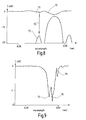
- the transmission an reflection spectrum of a single slanted Fiber Bragg Grating; and
- Fig. 9
- the transmission spectrum versus wavelength of a superposition of two slanted Fiber Bragg Gratings.
- In Figure 1,
identification reference 10 designates a Raman laser device in its entirety.Raman laser device 10 comprises a continuouswave pump laser 12, alength 20 of Raman amplifying fiber, afirst group 18 of wavelength selectors, asecond group 22 of wavelength selectors, and athird group 24 of wavelength selectors. - When viewed in the direction of light propagating from continuous
wave pump laser 12 throughlength 20 of Raman amplifying fiber, thefirst group 18 of wave-length selectors is arranged previous tointermediate span 20 of fiber, whereas thesecond group 22 of wavelength selectors and thethird group 24 of wavelength selectors are arranged behindintermediate span 20 of fiber. - The length of
Raman amplifying fiber 20 betweenpump laser 12 andwavelength selector 28 forms an embedded pump-cavity in which the pump wave emitted bypump laser 12 is reflected once byFBG 28. Likewise,wavelength selectors wavelength selectors wavelength selectors length 20 of Raman amplifying fiber. - Wavelength selectors 28 - 40 may be realized as Fabry-Perot interferometers. Alternatively, they may be realized as Fiber Bragg Gratings that are centered around the respective selected wavelengths. For a continuous pump wavelength of 1117 nm,
wavelength selectors wavelength selectors wavelength selectors - The pump light wave emitted by continuous
pump wave laser 12 is successively downshifted in frequency to the selected wavelengths of 1167 nm, 1223 nm and 1284 nm by means of the Raman effect. Accordingly, the selected wavelengths are, in general, chosen to be spaced apart from each other by the wavelength equivalent of one Stokes frequency. - As is generally known, the Stokes frequency indicates the amount of the frequency shift which is due to the Raman effect. Accordingly, a wave having a frequency shifted down from the frequency of a pump-wave by one Stokes frequency, is often called a Stokes. Since all
wavelength selectors 28 to 40 have a high reflectivity in the order of 99 %, light of the selected frequencies resonates in the respective cavity formed by the corresponding pair ofwavelength selectors - In contrast thereto, a plurality of further cavities is provided that emit the desired plurality of wavelengths, each cavity emitting a single wavelength. In Fig. 1, two such cavities are formed by
pairs Raman laser device 10. - The two cavities that provide for the output wavelengths are designated as a first cavity and a second cavity below. Wavelength selector 44 of the
first group 18 of wavelength selectors andwavelength selector 42 from thethird group 24 of wavelength selectors form the first cavity, in which lasing occurs at a first output frequency. Likewise,wavelength selector 46 of thethird group 24 of wavelength selectors andwavelength selectors 48 of thefirst group 18 of wavelength selectors form the second cavity in which lasing occurs at a second frequency. - Accordingly, respective first and second waves having a first power and a second power are generated in the first cavity and the second cavity, respectively. Since
wavelength selector 42 andwavelength selector 46 of thethird group 24 of wavelength selectors show a reflectivity that is reduced in comparison to the 99 % reflectivity of the wavelength selectors of thefirst group 18 andsecond group 22 of wavelength selectors, first and second beams are generated that are emitted by the respective cavity embedded inRaman amplifying fiber 20 bywavelength selectors -
Wavelength selector 42 may have a reflectivity of approximately 10 %, whereaswavelength selector 46 may have a high reflectivity of more than 40 %, in particular a reflectivity of approximately 60 % in an embodiment of the present invention. In prior art devices, the reflectivity is, usually, lower than 40% and the output is not stable at low output power at 14xx nm. Accordingly, the first beam that is coupled out bywavelength selector 42 is more powerful than the second wavelength coupled out bywavelength selector 46. Both the first and the second wavelength of 1351 and 14xx nm, respectively, get out of the laser already through the same fiber.Wavelength selector 42 of the first cavity may have a center wavelength of 1351 nm andwavelength selector 46 of the second cavity may have a center wavelength of 1428 nm. Like the other waves mentioned before, both output waves are subsequent Stokes waves generated by means of the Raman effect inRaman laser device 10. The reflectivity of theFiber Bragg Grating 46 may be adjusted by a known adjustment mechanism, that is by applying mechanical stress or heat by a respective means 47 controlled by acontrol device 49. - Figure 2 shows, schematically, a
line fiber 50 span which is pumped by theRaman laser device 10 of Figure 1.Arrow 52 represents the direction of signals propagating inline fiber 50. Accordingly, signals propagate throughline fiber 50 from the left to the right. The first and second waves that are generated byRaman laser device 10 are fed intoline fiber 50 such that they propagate in the reverse direction, that is from the right to the left. To use such counterpropagating pump-waves instead of pump waves that co-propagate with signals reduces the generation of noise inline fiber 50. - The first (powerful) Stokes wave of potentially 1351 nm pumps the
line fiber 50 with a power of approximately 1 W. Alongline fiber 50, this Stokes will transfer its power to the 1428 (small power) nm wavelength which is launched as a seed inline fiber 50 byRaman laser device 10. A typical power of a seed wave as launched is lower than 100 mW.
Further, power is transferred from the pumped seed wave to the signal wavelength, which is in range of 1530 - 1550 nm. - This transfer of energy is schematically depicted in Figure 3, in which
arrow 56 represents the center wavelength 1351 nm of the Stokes that is pumping line fiber 50 (first power coupled out from Raman laser device 10). Likewise,arrow 58 represents the center wavelength 1428 of the seed (second power coupled out of Raman laser device 10), andarrow 58 represents a center wavelength of the signals propagating inline fiber 50. The 1428 nm seed is called the first order pump, whereas the 1351 nm Stokes is called the second order pump. The condition for the 1351 nm pump Stokes to transfer its power to the 1428 nm seed wavelength while propagating alongline fiber 50 is that already a small power exists in the seed. - According to the invention, a small but stable power in the seed is achieved by attenuating the second power that is coupled out of the Raman laser device utilizing at least one Fiber Bragg Grating.
- The attenuation can be achieved by a single Fiber Bragg
Grating wavelength selector 46 that has a reflectivity that is higher than the reflectivity where highest output power is obtained. Figure 4 shows the output intensity of a laser as a function of the transmission. As is generally known, the reflectivity is equal to 1 - transmission. Accordingly, a maximum in transmission implies a corresponding minimum in reflectivity. As can be taken from Figure 4, the output intensity I increases initially with increasing transmission up to a maximum value I_max at a certain transmission T_opt which is lower than the maximum of the transmission (100%). Increasing the transmission beyond T_opt leads to a falling intensity. - To achieve a high output intensity, i.e. a high output power, any output mirror that terminates a laser cavity is usually designed to have a transmission (and corresponding reflectivity) that leads to a maximum output intensity.
This applies also to the case where a Fiber Bragg Grating is utilized as the output mirror. Such a utilization of a Fiber Bragg Grating having a transmission T_opt is generally known. - However, according to one embodiment of the present invention, the reflectivity (and transmission) of that
particular Fiber Bragg 46 that is used to couple the seed beam out of the respective cavity ofRaman laser device 10 is designed to show a suboptimal reflectiviy chosen such that it corresponds to transmission values left from the transmission value T_opt where maximum intensity occurs. - Accordingly, less power is coupled out of the respective laser cavity, and, therefore, more power remains in the respective laser cavity. Hence, two desired effects are achieved simultaneously: The increased amount of power remaining inside the respective laser cavity promotes or facilitates that the wave resonating in the cavity exceeds the lasing threshold. Thus, the stability of the wave resonating inside the cavity is enhanced. Since the stability of the emitted seed depends on the stability of the wave resonating inside the cavity, the stability of the emitted seed is also enhanced.
- Further, by decreasing the amount of power that is coupled out, the power of the generated seed wave is attenuated. It should be noted that the respective values are increased and decreased in comparison to a case in which a maximum of output power is desired.
- As an alternative, a classical
Raman laser device 10 having embedded cavities is supplemented with additional attenuators realized by slanted Fiber Bragg Gratings that are centered at each output wavelength and that are located spatially behind the output mirror. In such an embodiment, the transmission and reflection characteristics of the two gratings just add. - A slanted Bragg Grating is a standard grating tilted during photo-inscription with an angle between the fringes and the normal of the fiber axis. Due to this angle, the grating couples a part of the guided mode power into the cladding modes in a contra-propagative direction. The attenuation spectral shape is then given by the envelope of the coupling into the cladding modes. By properly choosing the angle, it is possible to reduce or optimize the value of back-reflection (i.e the attenuation i.e the power coupled backward in the cladding modes) and therefore the coupling of the fundamental mode in the contra-propagative direction.
- Fig. 5 illustrates schematically a length of
Raman amplifying fiber 16 having a reflectiveFiber Bragg Grating 46 serving as the output mirror for generating the seed beam and having an added slantedFiber Bragg Grating 62 located spatially behind the output mirror. Like the reflectivity ofFiber Bragg Grating 46, the attenuation of slantedFiber Bragg Grating 62 may be adjusted by a known adjustment mechanism, that is by applying mechanical stress or heat by a respective means controlled by a control device. -
Curve 64 in Fig. 6 illustrates the transmission of the reflectiveFiber Bragg Grating 46 andcurve 66 shows the corresponding reflection. Curve 68 in Fig. 7 shows the attenuating transmission of the slanted Fiber Bragg Grating 68 in the radiative modes. As mentioned above, the transmission of the two gratings just add. - In the following, two variations of this solution are considered.
- As a first variation, only a single slanted
Fiber Bragg Grating 62 is used instead of the combination of a reflectiveFiber Bragg Grating 46 and a slantedFiber Bragg Grating 62. The secondary reflection of the slantedFiber Bragg Grating 62 is then used to terminate the cavity at each output wavelength and to realize the function of reflection. The cladding mode wavelength is aligned on this secondary reflection wavelength and allows to transmit the output wavelength with an attenuation defined by the slanted Fiber Bragg Grating. - Fig. 8 illustrates resulting transmission and reflection properties that have been obtained by such a variation for coupling out a seed and attenuating same in order to achieve a stable low power seed.
Curve 70 corresponds to the transmission of the slanted FBG.Lobe 75 represents the transmission in the radiation modes, as curve 68 in fig. 7. By properly choosing the angle, it is possible to choose the appropriate value of attenuation in the cladding modes and the corresponding secondary reflection.Curve 72 depicts the reflection of the slanted FBG. The small lobes on the right and left are due to the secondary reflection and the main lobe between the small lobes is caused by the main reflection corresponding to the mode that is transmitted and back-reflected as a guided mode. - The high reflection is the main reflection corresponding to the guided mode and the small lobes are caused by the secondary reflection of this guided mode. It is the
secondary reflection 72 on the left that is used to assume the reflection function.Arrow 73 from the firstsmall lobe 75 of the transmission (on curve 70) to the left secondary reflection ofcurve 72 shows the wavelength where the laser operates. - The second variation provides a superposition of two slanted Fiber Bragg Gratings or of one FBG and one slanted FBG or the equivalent Moiré Grating.
- The resulting transmission spectrum versus wavelength of a superposition of two slanted Fiber Bragg Gratings is shown in Fig. 9. The primary reflection of the first slanted Fiber Bragg Grating is centered with the cladding mode of the second slanted Fiber Bragg Grating.
Transmission minimum 74 corresponds to the radiation mode of the first slanted Fiber Bragg Grating whileminimum 76 corresponds to the transmission of the first slanted Fiber Bragg Grating and the radiative mode of the second slanted Fiber Bragg Grating.Minimum 78 corresponds to the transmission of the second slanted Fiber Bragg Grating.Peak 76 is the one used.
Claims (9)
- Raman laser device (10) having a first cavity in which lasing occurs at a first frequency, and at least one second cavity in which lasing occurs at a second frequency, thereby generating respective first and second waves inside the respective cavities having a first power and a second power, respectively,
generating beams propagating outside the cavities by coupling out a part of the first power and a part of the second power utilizing respective first and second output mirrors, attenuating the part of the second power that is coupled out without attenuating the complementary part of the second power remaining in the second cavity,
the part of the second power that is coupled out is attenuated utilizing at least one Fiber Bragg Grating (46, 62), characterized in that the second output mirror has a reflectivity that is higher than the reflectivity where highest output power is obtained. - The Raman laser device (10) of claim 1, characterized in that the at least one Fiber Bragg Grating (46, 62) is a slanted Fiber Bragg Grating (62).
- The Raman laser device (10) of claim 2, characterized by the slanted Fiber Bragg Grating's (46, 62) attenuation being adjustable.
- The Raman laser device (10) of claim 3, characterized in that the slanted Fiber Bragg Grating's (62) attenuation is adjusted by applying mechanical stress or heat.
- The Raman laser device (10) of claim 2, characterized by comprising a control device (47, 49) that adjusts the Fiber Bragg Grating's reflectivity.
- The Raman laser device (10) of claim 1, characterized in that the part of the second power that is coupled out is attenuated by a slanted Fiber Bragg Grating (62) that is located spatially apart from the output mirror.
- The Raman laser device (10) of claim 6, characterized in that the output mirror is a Fiber Bragg Grating (46, 62).
- The Raman laser device (10) of claim 6, characterized by both the Fiber Bragg Grating (46) serving as an output mirror and the slanted Fiber Bragg Grating Fiber (62) being adjustable.
- The Raman laser device (10) of claim 1, characterized in that the part of the second power that is coupled out is attenuated by a superposition of two slanted Fiber Bragg Gratings or a slanted Fiber Bragg Gratings and a standard FBG.
Priority Applications (4)
| Application Number | Priority Date | Filing Date | Title |
|---|---|---|---|
| EP03290493A EP1458067B1 (en) | 2003-03-03 | 2003-03-03 | Multiple output raman fiber laser with stable and small output power for seed applications |
| AT03290493T ATE348425T1 (en) | 2003-03-03 | 2003-03-03 | RAMAN FIBER LASER WITH MULTI-WAVE LENGTH, STABLE, SMALL OUTPUT FOR SEED LASER APPLICATIONS |
| DE60310363T DE60310363T2 (en) | 2003-03-03 | 2003-03-03 | Raman fiber laser with multi-wavelength, stable, low output power for applications as a seed laser |
| US10/781,626 US7136401B2 (en) | 2003-03-03 | 2004-02-20 | Multiple output Raman fiber laser with stable and small output power for seed applications |
Applications Claiming Priority (1)
| Application Number | Priority Date | Filing Date | Title |
|---|---|---|---|
| EP03290493A EP1458067B1 (en) | 2003-03-03 | 2003-03-03 | Multiple output raman fiber laser with stable and small output power for seed applications |
Publications (2)
| Publication Number | Publication Date |
|---|---|
| EP1458067A1 EP1458067A1 (en) | 2004-09-15 |
| EP1458067B1 true EP1458067B1 (en) | 2006-12-13 |
Family
ID=32749000
Family Applications (1)
| Application Number | Title | Priority Date | Filing Date |
|---|---|---|---|
| EP03290493A Expired - Lifetime EP1458067B1 (en) | 2003-03-03 | 2003-03-03 | Multiple output raman fiber laser with stable and small output power for seed applications |
Country Status (4)
| Country | Link |
|---|---|
| US (1) | US7136401B2 (en) |
| EP (1) | EP1458067B1 (en) |
| AT (1) | ATE348425T1 (en) |
| DE (1) | DE60310363T2 (en) |
Cited By (6)
| Publication number | Priority date | Publication date | Assignee | Title |
|---|---|---|---|---|
| WO2010132493A1 (en) * | 2009-05-11 | 2010-11-18 | Ofs Fitel Llc | Systems and techniques for suppressing backward lasing in high-power cascaded raman fiber lasers |
| US8179594B1 (en) | 2007-06-29 | 2012-05-15 | Lockheed Martin Corporation | Method and apparatus for spectral-beam combining of fanned-in laser beams with chromatic-dispersion compensation using a plurality of diffractive gratings |
| US8199399B1 (en) | 2006-11-30 | 2012-06-12 | Lockheed Martin Corporation | Optical gain fiber having segments of differing core sizes and associated method |
| US8441718B2 (en) | 2009-11-23 | 2013-05-14 | Lockheed Martin Corporation | Spectrally beam combined laser system and method at eye-safer wavelengths |
| US8472763B1 (en) | 2005-07-29 | 2013-06-25 | Lockheed Martin Corporation | Spectral beam combination of laser beams |
| US8503840B2 (en) | 2010-08-23 | 2013-08-06 | Lockheed Martin Corporation | Optical-fiber array method and apparatus |
Families Citing this family (11)
| Publication number | Priority date | Publication date | Assignee | Title |
|---|---|---|---|---|
| US20070025660A1 (en) * | 2005-07-29 | 2007-02-01 | Su-Nam Lee | All-optical variable optical attenuator |
| JP5013851B2 (en) * | 2005-12-26 | 2012-08-29 | 京セラ株式会社 | Phase grating, phase grating with lens, and optical module |
| WO2008049187A1 (en) | 2006-10-25 | 2008-05-02 | Lxsix Photonics, Inc. | Tilted grating sensor |
| JP5323562B2 (en) * | 2008-03-31 | 2013-10-23 | 古河電気工業株式会社 | Cascade Raman laser |
| US7912099B2 (en) * | 2008-10-21 | 2011-03-22 | Gapontsev Valentin P | Method and apparatus for preventing distortion of powerful fiber-laser systems by backreflected signals |
| TWI377751B (en) * | 2008-12-04 | 2012-11-21 | Ind Tech Res Inst | All-fiber color laser and light-illuminating method thereof |
| US9366872B2 (en) | 2014-02-18 | 2016-06-14 | Lockheed Martin Corporation | Apparatus and method for fiber-laser output-beam shaping for spectral beam combination |
| CN104112970A (en) * | 2014-07-22 | 2014-10-22 | 中国科学院上海光学精密机械研究所 | All-fiber stimulated Raman scattering light stripper |
| CN106549292A (en) * | 2017-01-19 | 2017-03-29 | 中国人民解放军国防科学技术大学 | A kind of high-power random fiber laser based on inclined optical fiber grating |
| JP6523511B1 (en) * | 2018-03-30 | 2019-06-05 | 株式会社フジクラ | Fiber laser device, method of manufacturing fiber laser device, and setting method |
| CN110380326B (en) * | 2019-07-29 | 2020-10-23 | 武汉电信器件有限公司 | Optical signal output device and method, and storage medium |
Family Cites Families (7)
| Publication number | Priority date | Publication date | Assignee | Title |
|---|---|---|---|---|
| US5511083A (en) * | 1995-03-02 | 1996-04-23 | United Technologies Corporation | Polarized fiber laser source |
| US6310899B1 (en) * | 1998-04-15 | 2001-10-30 | Lucent Technologies Inc. | Cascaded raman resonator system and apparatus |
| US6407855B1 (en) * | 1999-10-29 | 2002-06-18 | Sdl, Inc. | Multiple wavelength optical sources |
| US6594288B1 (en) * | 2000-11-06 | 2003-07-15 | Cidra Corporation | Tunable raman laser and amplifier |
| WO2002075391A2 (en) * | 2001-03-16 | 2002-09-26 | Cidra Corporation | Optical grating-based filter |
| AU2002316478A1 (en) * | 2001-07-02 | 2003-01-21 | Ogg Technology Licensing, Llc. | Multi-wavelength optical fiber |
| DE60220369T2 (en) * | 2002-01-11 | 2007-09-20 | Alcatel Lucent | Cascade Raman fiber laser and optical system with such a laser |
-
2003
- 2003-03-03 DE DE60310363T patent/DE60310363T2/en not_active Expired - Lifetime
- 2003-03-03 EP EP03290493A patent/EP1458067B1/en not_active Expired - Lifetime
- 2003-03-03 AT AT03290493T patent/ATE348425T1/en not_active IP Right Cessation
-
2004
- 2004-02-20 US US10/781,626 patent/US7136401B2/en active Active
Cited By (7)
| Publication number | Priority date | Publication date | Assignee | Title |
|---|---|---|---|---|
| US8472763B1 (en) | 2005-07-29 | 2013-06-25 | Lockheed Martin Corporation | Spectral beam combination of laser beams |
| US8199399B1 (en) | 2006-11-30 | 2012-06-12 | Lockheed Martin Corporation | Optical gain fiber having segments of differing core sizes and associated method |
| US8345348B1 (en) | 2006-11-30 | 2013-01-01 | Lockheed Martin Corporation | Method and optical gain fiber having segments of differing core sizes |
| US8179594B1 (en) | 2007-06-29 | 2012-05-15 | Lockheed Martin Corporation | Method and apparatus for spectral-beam combining of fanned-in laser beams with chromatic-dispersion compensation using a plurality of diffractive gratings |
| WO2010132493A1 (en) * | 2009-05-11 | 2010-11-18 | Ofs Fitel Llc | Systems and techniques for suppressing backward lasing in high-power cascaded raman fiber lasers |
| US8441718B2 (en) | 2009-11-23 | 2013-05-14 | Lockheed Martin Corporation | Spectrally beam combined laser system and method at eye-safer wavelengths |
| US8503840B2 (en) | 2010-08-23 | 2013-08-06 | Lockheed Martin Corporation | Optical-fiber array method and apparatus |
Also Published As
| Publication number | Publication date |
|---|---|
| DE60310363D1 (en) | 2007-01-25 |
| DE60310363T2 (en) | 2007-04-12 |
| US20040174913A1 (en) | 2004-09-09 |
| US7136401B2 (en) | 2006-11-14 |
| EP1458067A1 (en) | 2004-09-15 |
| ATE348425T1 (en) | 2007-01-15 |
Similar Documents
| Publication | Publication Date | Title |
|---|---|---|
| EP1458067B1 (en) | Multiple output raman fiber laser with stable and small output power for seed applications | |
| EP0603925B1 (en) | Optical signal generator for telecommunication equipment | |
| US7616667B2 (en) | Broadband fiber laser | |
| US5991070A (en) | Optical amplifier with oscillating pump energy | |
| JP2000075150A (en) | Article including cascaded raman resonator of optical fiber | |
| JP4179662B2 (en) | Optical amplifier and active optical fiber | |
| US6876679B1 (en) | Systems and methods of operating an incoherently beam combined laser | |
| US6614823B2 (en) | Semiconductor laser device having a diffraction grating on a light reflection side | |
| US5910962A (en) | Multiwavelength fiber laser sources for fiberoptic networks | |
| US6624927B1 (en) | Raman optical amplifiers | |
| US6947463B2 (en) | Semiconductor laser device for use in a laser module | |
| US20030021314A1 (en) | Distributed bragg reflector semiconductor laser suitable for use in an optical amplifier | |
| US6768750B2 (en) | Multi-spectral line Raman laser | |
| KR20020085332A (en) | Erbium-doped fiber laser for long wavelength band | |
| WO2001065647A2 (en) | Cascaded raman resonator with seed source | |
| US7463411B2 (en) | Optical fiber amplifier | |
| US6618405B2 (en) | Semiconductor laser module and amplifier using the module | |
| CN103392276A (en) | Tunable pumping light source for optical amplifiers | |
| US20030138000A1 (en) | Cascaded Raman fiber laser, and optical system including such a laser | |
| JP2002368327A (en) | Semiconductor laser | |
| US20020141045A1 (en) | Optical fiber amplifier | |
| US7319707B2 (en) | L-band light source | |
| US6466363B1 (en) | Broadband amplification with first and second amplifiers having different pump wavelength requirements | |
| WO2023134438A1 (en) | Light beam processor | |
| JP2003031879A (en) | Optical device, optical fiber used therefor, pulse generator, optical amplifier, and fiber laser |
Legal Events
| Date | Code | Title | Description |
|---|---|---|---|
| PUAI | Public reference made under article 153(3) epc to a published international application that has entered the european phase |
Free format text: ORIGINAL CODE: 0009012 |
|
| 17P | Request for examination filed |
Effective date: 20031210 |
|
| AK | Designated contracting states |
Kind code of ref document: A1 Designated state(s): AT BE BG CH CY CZ DE DK EE ES FI FR GB GR HU IE IT LI LU MC NL PT RO SE SI SK TR |
|
| AX | Request for extension of the european patent |
Extension state: AL LT LV MK |
|
| AKX | Designation fees paid |
Designated state(s): AT BE BG CH CY CZ DE DK EE ES FI FR GB GR HU IE IT LI LU MC NL PT RO SE SI SK TR |
|
| GRAP | Despatch of communication of intention to grant a patent |
Free format text: ORIGINAL CODE: EPIDOSNIGR1 |
|
| GRAS | Grant fee paid |
Free format text: ORIGINAL CODE: EPIDOSNIGR3 |
|
| GRAA | (expected) grant |
Free format text: ORIGINAL CODE: 0009210 |
|
| AK | Designated contracting states |
Kind code of ref document: B1 Designated state(s): AT BE BG CH CY CZ DE DK EE ES FI FR GB GR HU IE IT LI LU MC NL PT RO SE SI SK TR |
|
| PG25 | Lapsed in a contracting state [announced via postgrant information from national office to epo] |
Ref country code: AT Free format text: LAPSE BECAUSE OF FAILURE TO SUBMIT A TRANSLATION OF THE DESCRIPTION OR TO PAY THE FEE WITHIN THE PRESCRIBED TIME-LIMIT Effective date: 20061213 Ref country code: CZ Free format text: LAPSE BECAUSE OF FAILURE TO SUBMIT A TRANSLATION OF THE DESCRIPTION OR TO PAY THE FEE WITHIN THE PRESCRIBED TIME-LIMIT Effective date: 20061213 Ref country code: CH Free format text: LAPSE BECAUSE OF FAILURE TO SUBMIT A TRANSLATION OF THE DESCRIPTION OR TO PAY THE FEE WITHIN THE PRESCRIBED TIME-LIMIT Effective date: 20061213 Ref country code: FI Free format text: LAPSE BECAUSE OF FAILURE TO SUBMIT A TRANSLATION OF THE DESCRIPTION OR TO PAY THE FEE WITHIN THE PRESCRIBED TIME-LIMIT Effective date: 20061213 Ref country code: LI Free format text: LAPSE BECAUSE OF FAILURE TO SUBMIT A TRANSLATION OF THE DESCRIPTION OR TO PAY THE FEE WITHIN THE PRESCRIBED TIME-LIMIT Effective date: 20061213 Ref country code: SI Free format text: LAPSE BECAUSE OF FAILURE TO SUBMIT A TRANSLATION OF THE DESCRIPTION OR TO PAY THE FEE WITHIN THE PRESCRIBED TIME-LIMIT Effective date: 20061213 Ref country code: NL Free format text: LAPSE BECAUSE OF FAILURE TO SUBMIT A TRANSLATION OF THE DESCRIPTION OR TO PAY THE FEE WITHIN THE PRESCRIBED TIME-LIMIT Effective date: 20061213 Ref country code: RO Free format text: LAPSE BECAUSE OF FAILURE TO SUBMIT A TRANSLATION OF THE DESCRIPTION OR TO PAY THE FEE WITHIN THE PRESCRIBED TIME-LIMIT Effective date: 20061213 Ref country code: SK Free format text: LAPSE BECAUSE OF FAILURE TO SUBMIT A TRANSLATION OF THE DESCRIPTION OR TO PAY THE FEE WITHIN THE PRESCRIBED TIME-LIMIT Effective date: 20061213 Ref country code: DK Free format text: LAPSE BECAUSE OF FAILURE TO SUBMIT A TRANSLATION OF THE DESCRIPTION OR TO PAY THE FEE WITHIN THE PRESCRIBED TIME-LIMIT Effective date: 20061213 Ref country code: BE Free format text: LAPSE BECAUSE OF FAILURE TO SUBMIT A TRANSLATION OF THE DESCRIPTION OR TO PAY THE FEE WITHIN THE PRESCRIBED TIME-LIMIT Effective date: 20061213 |
|
| REG | Reference to a national code |
Ref country code: GB Ref legal event code: FG4D |
|
| REG | Reference to a national code |
Ref country code: CH Ref legal event code: EP |
|
| REG | Reference to a national code |
Ref country code: IE Ref legal event code: FG4D |
|
| REF | Corresponds to: |
Ref document number: 60310363 Country of ref document: DE Date of ref document: 20070125 Kind code of ref document: P |
|
| PG25 | Lapsed in a contracting state [announced via postgrant information from national office to epo] |
Ref country code: SE Free format text: LAPSE BECAUSE OF FAILURE TO SUBMIT A TRANSLATION OF THE DESCRIPTION OR TO PAY THE FEE WITHIN THE PRESCRIBED TIME-LIMIT Effective date: 20070313 Ref country code: BG Free format text: LAPSE BECAUSE OF FAILURE TO SUBMIT A TRANSLATION OF THE DESCRIPTION OR TO PAY THE FEE WITHIN THE PRESCRIBED TIME-LIMIT Effective date: 20070313 |
|
| PG25 | Lapsed in a contracting state [announced via postgrant information from national office to epo] |
Ref country code: ES Free format text: LAPSE BECAUSE OF FAILURE TO SUBMIT A TRANSLATION OF THE DESCRIPTION OR TO PAY THE FEE WITHIN THE PRESCRIBED TIME-LIMIT Effective date: 20070324 |
|
| RAP2 | Party data changed (patent owner data changed or rights of a patent transferred) |
Owner name: ALCATEL LUCENT |
|
| PG25 | Lapsed in a contracting state [announced via postgrant information from national office to epo] |
Ref country code: PT Free format text: LAPSE BECAUSE OF FAILURE TO SUBMIT A TRANSLATION OF THE DESCRIPTION OR TO PAY THE FEE WITHIN THE PRESCRIBED TIME-LIMIT Effective date: 20070514 |
|
| NLV1 | Nl: lapsed or annulled due to failure to fulfill the requirements of art. 29p and 29m of the patents act | ||
| ET | Fr: translation filed | ||
| REG | Reference to a national code |
Ref country code: CH Ref legal event code: PL |
|
| PLBE | No opposition filed within time limit |
Free format text: ORIGINAL CODE: 0009261 |
|
| STAA | Information on the status of an ep patent application or granted ep patent |
Free format text: STATUS: NO OPPOSITION FILED WITHIN TIME LIMIT |
|
| 26N | No opposition filed |
Effective date: 20070914 |
|
| PG25 | Lapsed in a contracting state [announced via postgrant information from national office to epo] |
Ref country code: MC Free format text: LAPSE BECAUSE OF NON-PAYMENT OF DUE FEES Effective date: 20070331 Ref country code: IE Free format text: LAPSE BECAUSE OF NON-PAYMENT OF DUE FEES Effective date: 20070305 |
|
| PG25 | Lapsed in a contracting state [announced via postgrant information from national office to epo] |
Ref country code: GR Free format text: LAPSE BECAUSE OF FAILURE TO SUBMIT A TRANSLATION OF THE DESCRIPTION OR TO PAY THE FEE WITHIN THE PRESCRIBED TIME-LIMIT Effective date: 20070314 |
|
| PG25 | Lapsed in a contracting state [announced via postgrant information from national office to epo] |
Ref country code: EE Free format text: LAPSE BECAUSE OF FAILURE TO SUBMIT A TRANSLATION OF THE DESCRIPTION OR TO PAY THE FEE WITHIN THE PRESCRIBED TIME-LIMIT Effective date: 20061213 |
|
| PG25 | Lapsed in a contracting state [announced via postgrant information from national office to epo] |
Ref country code: LU Free format text: LAPSE BECAUSE OF NON-PAYMENT OF DUE FEES Effective date: 20070303 Ref country code: CY Free format text: LAPSE BECAUSE OF FAILURE TO SUBMIT A TRANSLATION OF THE DESCRIPTION OR TO PAY THE FEE WITHIN THE PRESCRIBED TIME-LIMIT Effective date: 20061213 |
|
| PG25 | Lapsed in a contracting state [announced via postgrant information from national office to epo] |
Ref country code: TR Free format text: LAPSE BECAUSE OF FAILURE TO SUBMIT A TRANSLATION OF THE DESCRIPTION OR TO PAY THE FEE WITHIN THE PRESCRIBED TIME-LIMIT Effective date: 20061213 Ref country code: HU Free format text: LAPSE BECAUSE OF FAILURE TO SUBMIT A TRANSLATION OF THE DESCRIPTION OR TO PAY THE FEE WITHIN THE PRESCRIBED TIME-LIMIT Effective date: 20070614 |
|
| PGFP | Annual fee paid to national office [announced via postgrant information from national office to epo] |
Ref country code: IT Payment date: 20110325 Year of fee payment: 9 |
|
| PG25 | Lapsed in a contracting state [announced via postgrant information from national office to epo] |
Ref country code: IT Free format text: LAPSE BECAUSE OF NON-PAYMENT OF DUE FEES Effective date: 20120303 |
|
| REG | Reference to a national code |
Ref country code: FR Ref legal event code: GC Effective date: 20140717 |
|
| REG | Reference to a national code |
Ref country code: FR Ref legal event code: RG Effective date: 20141016 |
|
| REG | Reference to a national code |
Ref country code: FR Ref legal event code: PLFP Year of fee payment: 13 |
|
| REG | Reference to a national code |
Ref country code: FR Ref legal event code: CA Effective date: 20150521 |
|
| REG | Reference to a national code |
Ref country code: FR Ref legal event code: CA Effective date: 20150521 |
|
| REG | Reference to a national code |
Ref country code: FR Ref legal event code: PLFP Year of fee payment: 14 |
|
| REG | Reference to a national code |
Ref country code: FR Ref legal event code: PLFP Year of fee payment: 15 |
|
| PGFP | Annual fee paid to national office [announced via postgrant information from national office to epo] |
Ref country code: FR Payment date: 20170322 Year of fee payment: 15 Ref country code: DE Payment date: 20170322 Year of fee payment: 15 |
|
| PGFP | Annual fee paid to national office [announced via postgrant information from national office to epo] |
Ref country code: GB Payment date: 20170322 Year of fee payment: 15 |
|
| REG | Reference to a national code |
Ref country code: DE Ref legal event code: R119 Ref document number: 60310363 Country of ref document: DE |
|
| GBPC | Gb: european patent ceased through non-payment of renewal fee |
Effective date: 20180303 |
|
| PG25 | Lapsed in a contracting state [announced via postgrant information from national office to epo] |
Ref country code: DE Free format text: LAPSE BECAUSE OF NON-PAYMENT OF DUE FEES Effective date: 20181002 |
|
| PG25 | Lapsed in a contracting state [announced via postgrant information from national office to epo] |
Ref country code: GB Free format text: LAPSE BECAUSE OF NON-PAYMENT OF DUE FEES Effective date: 20180303 |
|
| PG25 | Lapsed in a contracting state [announced via postgrant information from national office to epo] |
Ref country code: FR Free format text: LAPSE BECAUSE OF NON-PAYMENT OF DUE FEES Effective date: 20180331 |