-
The invention relates to a biodegradable implant or the like manufactured
of polymer-based material in accordance with the preamble of
claim 1.
-
In surgery, it is known to employ biodegradable, elongated, typically
tubular surgical implants and devices for supporting or combining or
dividing elongated organs, tissues or parts thereof. These objects
include various canals, ducts, intestines, blood vessels, tubes, such as
bronchial tubes, urinary tracts, nerves etc.
-
In this context, the biodegradable material refers to a material manufactured
of polymer, copolymer or polymer composition, the degradation
and/or absorbing of which material takes place by means of metabolic
reactions and/or secretion through kidneys, lungs or intestines or
skin.
-
A multitude of publications describe various tubular implants and surgical
devices manufactured of biostable or biodegradable materials.
Such implants are disclosed e.g. in publications US-3 108 357;
US-3 155 095; US-3 272 204; US-3 463 158; US-3 620 218;
WO 83/03752; WO 84/03035; Daniel and Olding, Plast. Rec. Surg. 74
(1984) 329; WO 90/04982; Van Andersdahl et al., Seminars in Urology,
Vol. II (1984) 180; Raja Subra Manian, ASAIO Journal 40 (1994) M584;
US-4 768 507; US-4 923 470; US-4 973 301; US-4 990 131;
US-4 994 066; US-5 019 090; EP-0 606 165 A1; WO 04/15583;
US-4 950 258; US-5 160 341 and US-5 085 629.
-
Known biostable, that is, in tissues practically non-degradable implants
and surgical devices of the above mentioned and corresponding type
have several shortcomings Their biostable parts, e.g. fibres, plastic
and metal threads or rings or tubes or the like remain in the system
even after an organ or a tissue has healed, and therefore such implants
and devices can later be harmful to the patient, causing e.g. infections,
inflammatory reactions, foreign body reactions and/or particles or corrosion
products or the like can be released therefrom, which can further
cause harmful reactions in the system
-
Known biodegradable implants and surgical devices and devices of a
corresponding type, e.g. of the type disclosed in the above-mentioned
publications, do not cause the same kind of chronic complications as
biostable implants and surgical devices, since biodegradable implants
and devices absorb and degrade entirely in the system finally leaving
the tissue entirely.
-
However, typically tubular implants and surgical devices involve the
drawback that they degrade evenly at their entirely length, that is, the
gradient of biodegration is directed to the centre of the cross section
along the entire length of the implant or the corresponding surgical
device. Thus, known elongated implants and surgical devices lose their
strength evenly at their entire length, and finally the whole implant or
surgical device loses its strength in a relatively short period of time at
its entire length. As a result, the implant or the surgical device disintegrates
evenly after having lost its strength in a short period of time or
even suddenly to small pieces and particles [cf e.g. Törmälä et al.
Biomed. Mater. Res. 25 (1991) 1]. In case the disintegrating implant or
surgical device is placed inside a hollow, elongated organ or tissue, it is
possible that an uncontrollable quantity of particles and pieces is
released from the disintegrating implant or the surgical device in a short
period of time, wherein some of these parts and particles can join
together and can contribute to a stoppage in the hollow tissue or organ,
such as in a flow duct of a blood vessel, urinary tract or other tubular
organ or tissue.
-
The present invention surprisingly discloses that when the implant or
the corresponding surgical device is manufactured in a controlled manner
to degrade so that it degrades according to its zone division, e.g.
gradually starting from one end, it is possible to eliminate the danger
that the prior art implants or corresponding surgical devices contribute
to a stoppage in the tubular tissue or organ, and in this manner it is
possible to improve the technical level in the field. A controlled degradation
according to zone division provides the further advantage that
the implant or the corresponding surgical device can be constructed to
react in biodegradation situations exactly according to a specifically
planned use.
-
For providing the above mentioned advantages, the implant or surgical
device according to the invention is thus mainly characterized by what
is presented in the characterizing portion of claim 1 and claim 2
-
An implant or a corresponding surgical device according to an advantageous
embodiment of the invention has an elongated configuration and
it starts to degrade in a controlled manner under tissue conditions in accordance
with zone division at its first end in a manner that the implant
disintegrates from said end onwards into small pieces and/or particles
and/or absorbable components in a manner that degradation proceeds
in a controlled manner towards the second end. Thus, small quantities
of small pieces, particles and corresponding degradation products are
constantly released from the implant, which pieces, particles and the
like can exit the interior of the hollow organ or tissue with fluids
excreted in fluid flows e.g. in urine, blood or by endocrine glands and/or
due to movements of muscles surrounding the tubular tissue.
-
An implant or a corresponding surgical device according to the invention
has advantageously an elongated configuration. It can be a tight
tube or a tube perforated at its surface, a single-threaded spiral twisted
of rod-like preform, a multi-threaded spiral or spiral-structured tube in
which the spirals are twisted in opposite directions and pass each other
above and below, forming a tubular braiding. The implant or the corresponding
surgical device according to the invention can also have a
configuration of a braided or knitted tube or the like. It is obvious to an
expert in the field that any biostable or biodegradable elongated implant
or a corresponding surgical device, e g. those presented in the publicaions
mentioned in the preamble of the specification, can be employed
as a model when constructing implants or corresponding surgical
devices in accordance with the invention.
-
implants or corresponding surgical devices in accordance with the
invention can be manufactured of various biodegradable polymers,
copolymers or polymer alloys disclosed in abundance in the literature
(e.g. in publication WO 90/04982 and in Finnish patent application
953694).
-
Implants or corresponding surgical devices in accordance with the
invention can have a non-reinforced structure, e.g. manufactured by
melt-processing techniques or solution techniques, or they can be
reinforced e.g. by using self-reinforcing or reinforcing by absorbable
polymeric or ceramic fibres.
-
Some advantageous embodiments of the implant or the corresponding
surgical device of the invention are presented in the accompanying
dependent claims.
-
The method according to the invention is mainly characterized by what
is presented in the characterizing portion of the independent claim relating
to the method.
-
The method for manufacturing an elongated implant or a corresponding
surgical device is based on the fact that the macroscopic and/or microscopic
structure of the implant or the corresponding surgical device is
formed, according to the method, to be such that the implant or the corresponding
surgical device disintegrates, according to a zone division
created thereto in a controlled manner under hydrolytic conditions into
small particles and/or pieces at its different parts at different times.
-
By regulating the macroscopic structure, the different parts of the implant
or the corresponding surgical device can be disintegrated at different
times by creating its walls to have different thickness at its different
parts. Provided that the micro-structure of the implant or the corresponding
surgical device is approximately homogeneous, usually the
thinner the wall structure, the faster the disintegration. Thus, when the
implant or the corresponding surgical device has a wall structure varying
regularly step by step from thin to thicker, the disintegration of the
implant or the corresponding surgical device takes place continuously
and/or gradually from the thinner end (a first end) to the thicker end (a
second end)
-
The microscopic structure, in its turn, can be regulated by modifying the
micro-structure of the implant or the corresponding surgical device.
Since the loss of strength in the implant or the corresponding surgical
device is based on the hydrolysis of the polymer structure, that it, to
opening of molecular bonds between the monomer units of the polymer,
the implant or the corresponding surgical devices of the invention can
be manufactured by providing thereto such micro-structures based on
zone division which micro-structures have a different hydrolysis behaviour
in different parts of the implant or the corresponding surgical
device. By changing the micro-structure of the implant or the corresponding
surgical device in its different parts, so that the hydrolyzation
of the biodegradable material either becomes more difficult or it facilitates,
it is possible to manufacture various types of biodegradable
implants and corresponding surgical devices according to a zone division
of the invention.
-
An elongated implant according to an advantageous embodiment of the
method is manufactured, in order to provide zone division, to have a
such geometry that the degradation speed of the implant is highest at
its first end and the degrading speed is retarding when travelling from
the fast-degrading end towards the slow-degrading end in the direction
of the longitudinal axis of the implant. Such degradation reaction is provided
e.g. by making the implant or the wall to be thicker at the second
end of the implant (slower-degrading end) and thinner at the first end
(faster-degrading end) in a manner that the wall thickness changes
regularly or gradually from its first end to the second end in the direction
of the longitudinal axis of the implant.
-
According to a second embodiment, the regular and/or gradual degradation
according to the zone division of the implant or the corresponding
surgical device is provided in a manner that the implant or the corresponding
surgical device or a preform thereof is pre-hydrolyzed in a
manner that the internal polymer structure of the biodegradable material
is cut into pieces in a controlled manner so that the average
molecular mass of the material is at its lowest value at the faster-degrading
first end of the elongated implant and it increases gradually
and/or step by step when travelling towards the slower-degradable
second end in the longitudinal axis of the implant, in which end the
molecular mass of the implant or the corresponding surgical device is
at its highest value.
-
According to a third embodiment, since the diffusion of water into the
biodegradable material is a crucial factor affecting to hydrolyzation, the
implants and corresponding surgical devices of the invention can be
manufactured by altering the micro-structure of the material in different
parts of the implant or the corresponding surgical device in a manner
that the diffusion of water into the implant or the corresponding surgical
device takes place in a more difficult manner at the slowly-degradable
second end than in the faster-degradable first end. Such implants or
corresponding surgical devices can be manufactured e.g. of partially
crystalline, biodegradable materials by manufacturing first an implant or
a corresponding surgical device having an even degree of crystallinity,
and then by heat treating it in a temperature gradient in a manner that
the degree of crystallinity is constantly increasing in the chosen dimension
of the implant, particularly in the direction of the longitudinal axis.
Thus, the implant starts to degrade faster at that end (the first end)
where the degree of crystallinity is lowest and degrades slower at that
end where the degree of crystallinity is highest (the second end).
-
Further, by altering the orientation level of the biodegradable material it
is possible to affect its hydrolysis reaction. Increasing the orientation
level retards the diffusion of water to the biodegradable material and
thus also its hydrolyzation and disintegration into pieces.
-
Another possible embodiment is to retard the diffusion of water to the
implant or the corresponding surgical device by various coatings. If the
biodegradable implant or the corresponding surgical device is coated
with at least one biodegradable polymer which has poor water-permeability,
by regulating the thickness of the coating layer it is possible to
make the implant to degrade in different ways at its different parts in a
manner that the part having the thickest coating layer degrades slowest
and the part having the thinnest coating layer degrades fastest.
-
The invention is illustrated in the following specification, in which some
examples of implants or corresponding surgical devices as well as embodiments
for their manufacturing in accordance with the invention are
presented with reference made to the accompanying drawings. In the
drawings
- Fig. 1
- shows a perspective view of an implant according to Example
1,
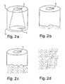
- Fig. 2
- shows as phases a―d a perspective-view series of the
degradation of the implant according to Example 1 and
Fig. 1 in a test arrangement according to Example 1,
- Fig. 3
- shows a perspective view of an implant according to Example
2,
- Fig. 4
- shows a side view of an apparatus according to Example 3,
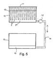
- Fig. 5
- shows a side view of an apparatus according to Example 4,
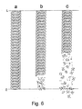
- Fig. 6
- shows schematically as phases a―c the degradation process
in hydrolysis of the spiral test pieces, that it, stents,
manufactured according to Example 4, and
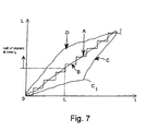
- Fig. 7
- shows schematically in L, t-co-ordination (the longitudinal
dimension of the implant, 0→, L, t = time) various degradation-time
divisions provided by the method of the invention.
-
The invention and its functionality is illustrated by means of the following
Examples which are not to restrict the scope of the invention.
Example 1
-
Cylindrical, tubular implants (diameter 12 mm) were manufactured of
commercial polyglycol (manufacturer. Boehringer/Ingelheim, Germany)
by injection-molding technique in a manner that the implants had a
conical duct inside so that at a first end of the implant the radius r1 of
the duct was 5 mm, and at a second end the radius r2 was 2 mm. Thus,
the thickness of the cylinder wall was 1 mm at the thinner-walled first
end and 4 mm at the thicker-walled second end, and the thickness of
the wall changed regularly in the entire length L = 12 mm of the implant.
The zone division was thus linear and continuous in the said implant.
-
Four implants were placed in separate baths in a phosphate-buffer
solution (pH = 6.1) at a temperature of 37°C, and a whirling flow state
was caused in the buffer solutions by means of mechanical mixing.
-
The implants were taken out of the whirling buffer solution to be examined
2, 4, 6 and 8 weeks after the hydrolysis had been started. Two
weeks after the hydrolysis, there were still no changes to be seen in the
implant (Fig. 2a). Four weeks after the hydrolysis, the implant had
clearly started to disintegrate at the thinner wall end in a manner that
the length L of the implant had become smaller with circa 2 mm and the
edge of the thinner wall was coarse (Fig. 2b). Six weeks after the
hydrolysis the implant had disintegrated almost to a one half of its
length in the direction of the longitudinal axis L (Fig. 2c), and after eight
weeks of hydrolysis the implant had totally disintegrated into the
hydrolysis solution (Fig. 2d).
-
For providing prior art comparison material, a cylindrical blank having
corresponding external dimensions as the said implant and a hole
(diameter 10 mm) inside was manufactured of polyglycol. The wall
thickness of this tubular blank was thus 1 mm When hydrolysing a
comparison blank of this type in a buffer solution it was noticed that two
weeks after the hydrolysis the tubular blank was visually seen unaltered,
but four weeks after the hydrolysis the blank had totally disintegrated
into particles in the buffer solution.
-
By means of the above mentioned comparative tests it was demonstrated
that by constructing a tubular blank (implant or a corresponding
surgical device) whose wall thickness varies from thick to thin in the
direction of the longitudinal axis of the blank, such a blank (implant or a
corresponding surgical device) degrades step by step in a manner that
the degradation is started at the thinner wall end, i.e., the gradient of
the degradation is in the longitudinal direction of the implant or the corresponding
surgical device
Example 2
-
There were manufactured implants having a height of 12 mm, a diameter
of 12 mm and a cylindrical central hole 1 in the direction of longitu-dinal
axis of the cylindrical configuration and with a constant diameter
of 10.
-
In the curved outer surface of the implants, there were drilled smaller
radial-directed holes extending to the central hole 1 in a following manner:
at the first end of the implant, close to its edge and in the direction
of the periphery, around the implant holes were drilled having a diameter
of 2 mm and extending to the central hole, between which holes a
strip of 0.5 mm was left in the outer surface of the implant in the direction
of periphery. Above this line of holes RR1 (Fig. 2), in a correspond-ing
manner as the line of holes RR1, there were drilled other holes
having a diameter of 1.5 mm having strips of 1 mm between them in a
manner that between the first RR1 and the second RR2 line of holes,
strips of 1 mm were left. Above the second line of holes RR2, in a corresponding
manner a third line of holes RR3 was drilled, having a
diameter of 1 mm and strips of 1.5 mm between them. The width of the
strips between the second RR2 and the third RR3 line of holes
was 1 mm. Above the third line of holes RR3, in a corresponding manner,
a fourth line of holes RR4 was drilled, having a hole diameter of
0.5 mm and strips of 2 mm between the holes. The distance between
the third RR3 and the fourth RR4 line of holes was 1.5 mm. Fig. 1
shows schematically an implant of the above mentioned type.
-
Implants of Fig. 3 were hydrolyzed under the hydrolysis conditions of
Example 1. Implants were examined after 2, 4, 6 and 8 weeks. After
two weeks of hydrolysis the implant was practically still unaltered. After
four weeks of hydrolysis the test implant had totally disintegrated at the
first line of holes RR1 (the first end) and partially down to the area and
in the area of the second line of holes RR2. After six weeks the implant
had disintegrated down to the third RR3 and fourth RR4 line of holes,
but the non-drilled upper part YO (the second end) of the implant was
still in one piece, although cracks and sheet erosion damages had
already formed in therein After eight weeks of hydrolysis the implant
had entirely disintegrated into small particles
Example 3
-
Preform having a width of 3 mm was manufactured by extrusion (single-screw
extruder) of polyglycol according to Example 1, which preform
was cooled to room temperature by means of moving cloth. Bars of 1 m
were cut out of the blank. A series of bars 2 were vertically attached
parallel at the same horizontal level at the second end to a chuck jaw
structure 3 of a pre-hydrolysis apparatus according to Fig. 4. The chuck
jaw structure 3 had been coupled to a vertical conveyor 5 in connection
with a body 4, by means of which vertical conveyor it was possible to
lift and lower a series of bars 2T slowly in the vertical direction. The
lower ends of the series of bars 2T were thus free ("free end"). By
means of the vertical conveyor 5 the bars 2 were pre-hydrolyzed in a
buffer solution of Example 1 at a temperature of 37°C by lowering them
slowly in a buffer solution 7 in a tank 6, placed below the bar series 2T,
by means of the vertical conveyor 5 of the chuck jaw structure 3, and by
lifting them back from the solution to a room temperature by using the
vertical conveyor 5. The lifting speed of the bar series 2T was 50 cm in
an hour (50 cm/h), and the lifting speed of the blank was also 50 cm in
an hour (50 cm/h), wherein the total term of one lift cycle was 4 hours.
The series of bars 2T comprised four pieces of bars T, which were
treated in hydrolysis. 40 dipping treatments were performed for the
series of bars 2T. The surface of the buffer solution 7 was during the
treatments at a constant height, which was maintained by a pump
arrangement 8 and an overflow arrangement 9.
-
The pre-hydrolyzed bars 2 were dried in a vacuum at an raised temperature
and they were drawn at a temperature of 160°C to orientated
blanks to a drawing ratio of 2 5, wherein orientated polyglycol blanks
having a width of 0.9 mm were obtained. The blanks were wound
around a heated steel tube (T = 180°C) (the outer diameter of the steel
tube = 8 mm) in a manner that spirals (stents) having a total length of
80 mm were obtained The steel tubes were rapidly cooled by means of
an internal air flow, wherein the spirals (stents) wound around the steel
tube could be detached
-
Stents were hydrolyzed 1, 2, 3 and 4 weeks in a buffer solution according
to Example 1, at a temperature of 37°C, under test conditions of
Example 1. The stent that had been one week in hydrolysis had started
to disintegrate at its pre-hydrolyzed end. Of the stents that had been
two weeks in hydrolysis, a piece of 20 mm had been disintegrated from
that end which, in a preform state, had a stronger pre-hydrolysis treatment
("free end"). More than a half of the stent that had been hydrolyzed
three weeks had been disintegrated, starting from the free end,
and after four weeks of hydrolysis the entire pre-hydrolyzed stent had
disintegrated into pieces.
-
For providing comparison material, stents were used which were extruded
and drawn in a similar manner as the above-presented pre-hydrolyzed
stents but which comparison stents were not pre-hydrolyzed.
The comparison stents preserved their structure practically unaltered
for 1, 2 and 3 weeks. After four weeks of hydrolysis the comparison
stents were broken into several pieces and disintegrated particles
had also detached from them.
Example 4
-
Cylindrical preform having a diameter of 3 mm was manufactured of
amorphous (non-crystalline) lactide copolymer (Resomer, UD molecular
ratio 85/15, Mv = 200,000, manufactured Boehringen/lngelheim,
Germany) by extrusion (single-screw extruder), which preform was
cooled to a room temperature on a moving cloth. A pre-hydrolysis
apparatus according to Fig. 5 was created for the test arrangement. Out
of the above mentioned preform, bars 2 having a length of 1 m were cut
and placed as a series of bars 2T to a vertical, isolated tank 10 at a
mounting bracket 11 belonging to the apparatus in a manner that the
bars 2 were apart from each other in the vertical direction. By using a
pump 12 in the lower part of the tank, phosphate buffer solution 15
according to Example 1 was pumped at a temperature of 70°C slowly to
the tank in a manner that the filling of the tank 10 took 10 hours. As
soon as the fluid surface had risen to the level of the upper ends of the
bars in the series of bars 2T, the emptying of the tanks 10 was slowly
started to a reserve tank 13 through a pump 12 along the connective
tube line 14 Also the emptying phase lasted 10 hours Thus, the total
length of the hydrolysis cycle was 20 hours. The pre-hydrolysis cycle
for the bars was repeated 20 times
-
After the pre-hydrolysis, the bars 2 to be examined were dried in a vacuum
furnace at an increased temperature. Subsequently, the preforms
were drawn at a temperature of 80°C to a drawing ration of 5, wherein
orientated billets having a thickness of 0.7 mm were obtained.
-
The billets were wound into spirals (stents) having a length of 80 mm
around a heated steel tube (T = 90°C) having an outer diameter of
80 mm, the steel tube was cooled, the stent (Fig. 6a) was detached,
dried in a vacuum, packed in an A1 foil bag and gamma-sterilized.
-
Pre-hydrolyzed stent were further hydrolyzed in a buffer solution of Example
1, at a temperature of 37 C under test conditions according to
Example 1. The hydrolysis times were 15, 25 and 60 weeks. After 15
weeks of hydrolysis, a piece of the length of 1.5 cm had disintegrated
into several small pieces (Fig 6b) from the second end of the examined
stent. The disintegration had taken place at that end of the stent which
in the preform phase had been on the bottom of the pre-hydrolysis tank,
i.e., at the end which had the strongest pre-hydrolysis treatment. After
25 weeks, approximately a half of the stent had disintegrated into
pieces of various sizes (Fig. 6c) from the pre-hydrolyzed end. After 60
weeks the stent had entirely disintegrated into small pieces.
-
For providing comparison material, orientated and gamma-sterilized
stent of a corresponding type which was not pre-hydrolyzed was used.
After 15 weeks the stent was still in one piece, as it was after 25 and 40
weeks. When the hydrolysis was continued by using four parallel samples,
the stents broke off at their central area or at an area close to
either of the ends without any regularity after 45 to 60 weeks of
hydrolysis.
-
A stent according to this example can advantageously be used in
treatment for e g. constrictions or retentions of the lower urinary tracts
(urethra) (in the area of prostate or penile urethra) or e g in treatment
for strictures of bile duct or pancreas duct
Example 5
-
Tube having an outer diameter of 3 mm and wall thickness of 0.7 mm
was manufactured of polydioxanone sutures (PDS sutures, manufacturer:
Ethicon, Germany; size 2 USP), by melting them in nitrogen
atmosphere in single-screw extruder. The tube was cut into pieces of
1 m.
-
Pieces of the PDS-tube were attached in a vertical position on the
mounting bracket in a manner that the upper ends of the PDS-tubes
were left above the hydrolysis fluid. The PDS-tubes were pre-hydrolyzed
by a pre-hydrolysis apparatus of Example 4 (Fig. 5) by means of
a phosphate-buffer solution of 40°C by employing a 20-hour fill-empty
cycle according to Example 4 The cycle was repeated for 25 times.
-
The tubes were dried and they were hydrolyzed under the conditions
according to Example 1 at a temperature of 37 C. After four weeks of
hydrolysis, the tubes had clearly started to disintegrate at that end
(lower end) which had the strongest pre-hydrolysis treatment. The
upper ends of the tubes, which had been attached to the bracket, were
visually seen unaltered. After six weeks of hydrolysis, over a half of the
length of the tubes had disintegrated from the lower part onwards, and
after eight weeks of hydrolysis the tubes were entirely disintegrated.
-
Corresponding non-pre-hydrolyzed tubes were used as comparison
tubes. Under the test conditions of Example 1, the comparison tubes
broke off into several pieces without regularity between 5 to 8 weeks.
-
A tube according to this example can be used as a stent e.g. between
kidneys and urinary bladder in treatment of strictures or retentions of
upper urinary tracts (ureter)
Example 6
-
A series of tests according to Example 1 was carried out by using the
following materials
- Poly-L-lactide (Mw 750,000)
- Glycol/trimethylene-carbonate copolymer (PGA/TMC)
- Lactide/ε-caprolactone copolymer (molecular ratio 60/40, Mw
100,000)
- Poly-β-hydroxide-butyrate
- Poly-ε-caprolactone
-
It was noticed that the hydrolysis tests provided corresponding results
as obtained in Example 1.
Example 7
-
A series of tests according to Example 2 was carried out by using the
following materials:
- Poly-L-lactide (Mw 750,000)
- Glycol/trimethylene-carbonate copolymer (PGA/TMC)
- Lactide/ε-caprolactone copolymer (molecular ratio 60/40, Mw
100,000)
- Poly-β-hydroxide-butyrate
- Poly-ε-caprolactone
-
The samples degraded mainly as in Example 2 in a manner that their
degrading started at the end having the largest holes.
Example 8
-
A series of tests according to Example 3 was earned out by using the
following materials:
- Poly-L-lactide (Mw 750,000)
- Glycol/trimethylene-carbonate copolymer (PGA/TMC)
- Lactide/ε-caprolactone copolymer (molecular ratio 60/40, Mw
100,000)
- Poly-p-hydroxide-butyrate
- Poly-ε-caprolactone
-
The samples degraded mainly as in Example 3 in a manner that their
disintegrating started at the end that was stronger pre-hydrolyzed
Example 9
-
A series of tests according to Example 5 was carried out by using the
following materials:
- Poly-L-lactide (Mw 750,000)
- Glycol/trimethylene-carbonate copolymer (PGA/TMC)
- Lactide/ε-caprolactone copolymer (molecular ratio 60/40, Mw
100,000)
- Poty-β-hydroxide-butyrate
- Poly-ε-caprolactone
-
The tubular samples degraded mainly as in Example 5 in a manner that
the disintegrating started at the end that was stronger pre-hydrolyzed.
Example 10
-
Bar having a thickness of 3 mm was manufactured of poly-L-lactide
(manufacturer: CCA Purac, Holland, Mw 750,000) by single-screw
extruder, which bar was cooled in air by a moving cloth. The crystalline
ratio of the bar was 20 % as defined by DSC-technique. A piece having
a length of 20 cm was cut out of the bar and a half of it was wrapped
inside a resistance tape, the temperature of which was adjusted to 120°
C. The resistance tape was held around the half of bar for approximately
20 minutes, during which time post-crystallizing of the material
took place. To that part of the rod which was treated with resistance
tape, a crystalline ratio of 35 % was obtained. The rod was placed in
hydrolysis of a phosphate solution at a temperature of 37°C (test
arrangement according to Example 1), and the reactions of the rod
were examined under hydrolysis conditions. After 12 months of
hydrolysis the non-heat-treated (non-post-crystallized) part of the rod
broke off into several pieces, whereas the post-crystallized part of the
rod preserved its configuration at this phase and broke off into pieces
only after 15 months of hydrolysis.
Example 11
-
Cylindrical preform having a thickness of 3 mm was manufactured of
poly-L/DL-lactide (L/DL-molecular ratio 70/30, incl. viscosity 5 8 dl/g,
trade name RESOMER LR 708, manufacturer. Boehringer, Ingelheim,
Germany) by extrusion (single-screw extruder), which preform was
cooled to a room temperature. Pieces of 30 cm were cut out of the
preform and a part having a length of 10 cm was turned at the centre of
them to be conical in a manner that the diameter of the thicker end was
3 mm and the diameter of the thinner end was 2 mm. The preforms
were drawn through a conical nozzle heated to a temperature of 70°C,
which nozzle had a hole with a round cross section, the smallest diameter
of the hole being 2 mm at the exit end of the conical configuration.
Due to the nozzle drawing the thinner end of the conical part of the
preforms remained unaltered and the thicker end was modified in a
manner that its diameter altered from 3 mm to 2 mm, when the material
was orientated to the drawing direction. The nozzle drawing was carried
out under tension and the billets were cooled to a room temperature
under tension. The billets were hydrolyzed under test conditions of
Example 1 and the preservation of their configuration was examined.
All the billets broke off at their non-modified part after approximately 35
weeks of hydrolysis and the disintegration proceeded as a function of
time regularly towards the stronger orientated end. The final disintegration
of the orientated ends of the billets took place approximately 45
weeks after the hydrolysis
Example 12
-
Self-reinforced polyglycol rods having a diameter of 2 mm were manufactured
of Dexon sutures (manufacturer: Davis + Geck, England) in a
hot mold by sintering in accordance with a method described in the
publication P. Törmälä et al., J Biomed Mat Res., Vol. 25, (1991), p. 5.
The lengths of the rods was 70 mm. The rods were coated at a second
end for the length of 35 mm, by dipping the rods in a 5 %-chloroform
solution of polydiaxanone for several times in a manner that the dissolvent
was now and then evaporated away. As a result, 50 µm thick layers
of PDS were obtained on the surface of the said area in the rods.
PDS-coated rods were hydrolyzed in a half of their length under
hydrolysis conditions of Example 1 After two weeks of hydrolysis all
the rods were in one piece After four weeks of hydrolysis, the rods had
swollen at their non-coated part and vertical cracks and breaks were
formed on the surface of the non-coated part After six weeks of
hydrolysis the non-coated parts of all the rods (10 pieces) had disintegrated
in the buffer solution, whereas the PDS-coated parts of the rod
were whole. After ten weeks of hydrolysis also the PDS-coated parts of
the rod had disintegrated.
-
With reference to the above presented examples the degradation of an
implant manufactured according to the invention can thus be provided
in the direction (longitudinal direction) of one dimension in a controlled
manner by several various means. The embodiments presented in the
above examples can naturally be combined; e.g. the implant of Fig. 3
can be treated with pre-hydrolysis by employing the apparatus according
to Figs. 4 or 5. Apparatus according to Figs. 4 and 5 can be used
for performing gradual pre-hydrolysis treatment in the longitudinal
direction of the bars, at least in a part of the length of the bars. Also
plate-like or three-dimensional pieces can be treated by means of
treatment according to Figs. 4 and 5, wherein the degradation is controlled
two or three dimensionally. Correspondingly, an apparatus
according to Figs. 4 and 5 can be used for treating plates and corresponding
form pieces, e.g. by combining a rotation or a corresponding
movement of plates or corresponding form pieces to the relative
movement between the plates and the pre-hydrolysis solution.
-
As to Example 2 and Fig. 3 it is to be noted that perforation RR1.. can
also be replaced by notchings or groovings, at least partially, wherein
the wall of the implant or the corresponding surgical device is not
penetrated.
-
Fig. 7 shows schematically some degradation patterns of controlled
degradation in L,t-co-ordination, where the vertical axis 0 → L illustrates
one dimension, e.g. length, of the implant or the corresponding
surgical device, the degradation gradient being parallel with this
dimension, wherein the degradation is controlled, and the horizontal
axis t illustrates the time spent for hydrolysis conditions. A curve A
illustrates substantially linear continuous degrading (e.g. embodiments
according to Figs. 1, 2 and 6) where mainly absorbable components
and/or smaller particles are created A curve B, in its turn, illustrates at
least partially non-continuous controlled degradation e g according to
Fig. 3, in which degradation (according to the dimensions of the strips)
also particles and/or small pieces come off in addition to absorbable
components. It is obvious to an expert in the field that e.g. by concentrating
the pre-hydrolysis treatment in different ways in different parts of
the bar it is possible to obtain a most diverse range of controlled degradation
patterns, e.g. curves C and D in Fig. 7, wherein C illustrates
the non-continuous point C1 in the degradation process and D illustrates
the accelerated degradation in the initial phase as a substantially continuous
total degradation. Thus, in Fig. 7 the curves B and C are of the
form L = Σfn(ti), wherein fn(t) can be any continuous function n = 1...m
and ti = a given interval ti ≠ t and ti < t, when L is in the area Li.
-
The elongated implant or the corresponding surgical device is a particularly
advantageous embodiment for supporting or combining or separating
elongated organs, tissues or parts thereof, wherein the implant under
tissue conditions starts to degrade in a controlled manner from its
first end onwards in a manner that the implant degrades (disintegrates
or absorbs) into small pieces and/or particles and/or absorbable components
from the said end onwards, in a manner that the degradation
proceeds in a controlled manner towards the second end according to
zone division in a manner that different zones detach in a controlled and
planned order from the macroscopic structure of the implant or the corresponding
surgical device. The speed of degradation of the implant or
the corresponding surgical device is highest at the first end of the implant
and it retards when travelling from the fast-degrading first end
towards the slow-degrading second end in the longitudinal axis of the
implant. In this situation, the thickness of the wall is narrower in the
fast-degrading first end than in the slow-degrading second end and/or
its area/volumetric unit is larger in the fast-degrading first end than in
the slow-degrading second end and/or it is pre-hydrolyzed in a manner
that a stronger pre-hydrolysis is directed to the material of the implant
or the corresponding surgical device in the fast-degrading first end than
in the slow-degrading second end. The implant or the corresponding
surgical device has an elongated configuration of a bar, tube or a spiral-structured
helix or it has a structure braided or knitted of fibres.
-
The implant or the corresponding surgical device of the invention can
also be bioactive, i.e., it can contain at least one organic or inorganic
bioactive substance, such as antibiotics, chemotherapeutic agent,
agent accelerating wound healing (e.g. angiogeneous growth factors),
bone growth factor (bone morphogenic proteins, BMP) etc. Such bioactive
implant materials are particularly advantageous in clinical use
since, in addition to the mechanical effect, they have biochemical,
medical and other effects for healing and ossification of organs and tissues.
The bioactive substance can also be placed on the surface of the
implant or the corresponding surgical device, particularly on a coating
layer, e.g. mixed in a biodegradable polymer. The implant or the corresponding
surgical device contains, or it can have on its surface in a
special coating layer, x-ray positive (contrast) agent, such as ceramic
powder (e.g. hydroxide-apatite, zirconium-oxide, calcium phosphate
powder) or organic x-ray positive agent (e.g. angiographic contrast
agent, such as iopamidol). By means of x-ray positive additive (contrast
agent) of this type the operating surgeon is able to see the implant or
the corresponding surgical during the insertion, or he can check the
position of the implant or the corresponding surgical device immediately
after the implantation.
-
It is obvious that implant materials according to the invention can further
contain various additives for facilitating the processability of the
material (e.g. stabilizers, antioxidants or softeners) or for altering its
properties (e.g. porosifying agents, i.e., blowing agents, softeners or
powder-like ceramic materials or biostable fibres, such as polyaramide
or carbon fibres) or for facilitating its handling (e.g. colorants).The
implant can also be manufactured of a single fiber or multiple set of
fibres which are wound spirally or knitted or woven to a longitudinal
tubular structure.