EP1464918B1 - Method and apparatus for measuring the position of a magnet relative to a measuring place - Google Patents
Method and apparatus for measuring the position of a magnet relative to a measuring place Download PDFInfo
- Publication number
- EP1464918B1 EP1464918B1 EP04003793.9A EP04003793A EP1464918B1 EP 1464918 B1 EP1464918 B1 EP 1464918B1 EP 04003793 A EP04003793 A EP 04003793A EP 1464918 B1 EP1464918 B1 EP 1464918B1
- Authority
- EP
- European Patent Office
- Prior art keywords
- magnetic field
- magnet
- measuring
- measuring location
- measured
- Prior art date
- Legal status (The legal status is an assumption and is not a legal conclusion. Google has not performed a legal analysis and makes no representation as to the accuracy of the status listed.)
- Expired - Lifetime
Links
- 238000000034 method Methods 0.000 title claims description 13
- 238000005259 measurement Methods 0.000 claims description 16
- 238000011156 evaluation Methods 0.000 description 10
- 206010028980 Neoplasm Diseases 0.000 description 2
- 238000001514 detection method Methods 0.000 description 2
- 230000015572 biosynthetic process Effects 0.000 description 1
- 238000005516 engineering process Methods 0.000 description 1
- 238000003780 insertion Methods 0.000 description 1
- 230000037431 insertion Effects 0.000 description 1
- 230000002452 interceptive effect Effects 0.000 description 1
- 238000012804 iterative process Methods 0.000 description 1
- 230000007774 longterm Effects 0.000 description 1
- 238000013178 mathematical model Methods 0.000 description 1
- 230000003068 static effect Effects 0.000 description 1
- 230000001629 suppression Effects 0.000 description 1
Images
Classifications
-
- G—PHYSICS
- G01—MEASURING; TESTING
- G01B—MEASURING LENGTH, THICKNESS OR SIMILAR LINEAR DIMENSIONS; MEASURING ANGLES; MEASURING AREAS; MEASURING IRREGULARITIES OF SURFACES OR CONTOURS
- G01B7/00—Measuring arrangements characterised by the use of electric or magnetic techniques
- G01B7/003—Measuring arrangements characterised by the use of electric or magnetic techniques for measuring position, not involving coordinate determination
-
- G—PHYSICS
- G01—MEASURING; TESTING
- G01D—MEASURING NOT SPECIALLY ADAPTED FOR A SPECIFIC VARIABLE; ARRANGEMENTS FOR MEASURING TWO OR MORE VARIABLES NOT COVERED IN A SINGLE OTHER SUBCLASS; TARIFF METERING APPARATUS; MEASURING OR TESTING NOT OTHERWISE PROVIDED FOR
- G01D5/00—Mechanical means for transferring the output of a sensing member; Means for converting the output of a sensing member to another variable where the form or nature of the sensing member does not constrain the means for converting; Transducers not specially adapted for a specific variable
- G01D5/12—Mechanical means for transferring the output of a sensing member; Means for converting the output of a sensing member to another variable where the form or nature of the sensing member does not constrain the means for converting; Transducers not specially adapted for a specific variable using electric or magnetic means
- G01D5/14—Mechanical means for transferring the output of a sensing member; Means for converting the output of a sensing member to another variable where the form or nature of the sensing member does not constrain the means for converting; Transducers not specially adapted for a specific variable using electric or magnetic means influencing the magnitude of a current or voltage
Definitions
- the invention relates to a method and a device for measuring the position, which have a magnet and a measuring location, which is in the magnetic field of the magnet to each other, wherein the magnet or the measuring location occupies a predetermined stationary position in the measurement.
- US 6,304,082 B1 is a multi-axis magnetometer for measuring the magnetic field strength in three orthogonal axes (X, Y, Z) known.
- US 5,622,169 a device and a method for locating a medical tube in the body of a patient, wherein on the medical tube, a permanent magnet is arranged, which has a strong magnetic field.
- a sensor device with preferably two magnetic coils is brought into the vicinity of the body to be tested and detects the static magnetic field associated with the permanent magnet.
- the output signals of the two sensor coils are evaluated, and differential signals of the two sensor signals are formed.
- magnetic sensors can be designed in such a way that they consist of three mutually perpendicularly arranged magnetic coils in order to carry out a measurement at two locations in each of all spatial directions.
- the publication US 6 129 668 discloses a system and method for determining the location and orientation of a medical device for long-term use, wherein a magnet is connected to the medical device.
- a magnet is connected to the medical device.
- three or more sets of magnetic sensors are used in which the sensor elements are arranged in a known manner. Each sensor element detects the strength of the magnetic field generated by the magnet in the three-dimensional space and outputs a corresponding sensor signal.
- the magnetic field gradient can also be determined.
- An iterative process is used to determine the actual location and orientation of the magnet. Predicted magnetic field values are compared with actually measured values and thus a detection result is concluded. Further steps will refine this detection result. The further steps take place until a desired degree of deviations is reached.
- the publication US 5,762,064 discloses a medical magnetic positioning system and method for determining the position of a magnet within a body, wherein at least two spaced-apart magnetic sensors are disposed on the body proximate a desired position of the magnet.
- the three-dimensional magnetic field of the magnet is detected by means of the at least two magnetic sensors and it can be determined from the at least two magnetic sensors after a corresponding evaluation of the desired location of the magnet.
- the magnetic sensors are triaxially measuring sensors, and both the location and the spatial orientation of the magnet with respect to the position of the magnetic sensors is determined.
- US Pat. No. 6,385,482 B1 a device and a method for determining a position, wherein a signal emitter unit is preferably arranged within a body, for example in the vicinity of a part to be examined, such as a tumor.
- the signals emitted by the signal emitter unit can be detected outside the body by means of corresponding receiver devices, so that the desired position, for example of the tumor, can be detected in an exact manner.
- the present invention is based on the object, an initially mentioned method and an aforementioned device in such a way that the mutual spatial positioning of a magnetic field generating magnet and a lying in the magnetic field location uninfluenced by interference fields can be determined.
- this object is achieved by the features of claim 1 and in the device by the features of claim 2.
- the magnetic field strength and / or the gradient at the measurement location becomes three-dimensional, i. determined in three orthogonal axes. From a deviation of the three-dimensionally determined magnetic field strength and / or the gradient of a reference magnetic field strength and / or reference magnetic field gradients, in which or at which the magnet and the measuring location have predetermined positions, the position measurement value for the relative position of magnet and Measuring location are formed to each other.
- the gradient reflects the curvature and direction of the magnetic field at the measuring location.
- 3D sensors three-dimensionally measuring sensors
- the signals corresponding to the position contain information both about the spatial location (x, y, z) and information about the direction or orientation with respect to the three spatial axes (X, Y, Z).
- At least four magnetic field sensors are provided, each of which magnetic field sensor measures the magnetic field strength three-dimensionally, i. in the three orthogonal X, Y, Z axes.
- the difference quotient of the field strength of the magnetic field is formed from at least two sensor signals and from the deviation of this difference quotient of a reference difference quotient, in which the magnet and the measuring location assume predetermined positions, the position measurement value for the relative position of the magnet and the measuring location is determined relative to each other.
- the partial difference quotients associated with the respective orthogonal axes in the X, Y and Z directions result in the gradients of the spatially extended magnetic field at the respective measuring location.
- the magnet which generates the magnetic field can be designed as a permanent magnet or as an electromagnet.
- a modulated magnetic field can be generated, wherein the strength and direction of the modulation measured at the measuring location are evaluated to determine the relative position from magnet to measuring location.
- either the magnet or the measuring location is arranged at a predetermined known stationary position.
- rotational movements and translational movements and combinations of these types of movement and the respective actual position of the moving component, in particular the operating element with which the magnet or measuring location is firmly connected can be detected in three orthogonal coordinates.
- the gradient of the magnetic field or the magnetic field strengths at the measuring location in the three orthogonal X, Y and Z axes can be determined at four known or specific measuring points with three-dimensionally measuring magnetic field sensors.
- the magnetic field sensors can be arranged on a circumference around a center forming the measuring location.
- the magnetic field strengths present at at least two measuring points are preferably determined by magnetic field sensors and the deviation from the assigned reference magnetic field strengths of the magnetic field sensors Position measurement determined.
- the magnetic field intensities of two measuring point pairs are evaluated for the determination of the position measured value.
- the method and the device are preferably used in the contactless generation of actuating signals or control signals in operating elements, for example switches and the like.
- operating elements for example switches and the like.
- the control elements or operating elements for generating the control signals or control signals can be moved three-dimensionally fixed with the magnets at a fixed measuring location or fixed to the measuring location with fixed magnets.
- the position measuring signals generated by the evaluation device then form the actuating signals or control signals for the devices to be operated.
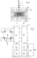
- a magnet 2 is attached to an operating element, for example in the form of a two-armed lever at the end of a lever arm.
- the magnet 2 which may be a permanent magnet or electromagnet, forms a magnetic field 3 with a specific field line direction. The direction the field strength coincides with the direction of the field lines in each point of the field.
- a measuring location 4 is arranged stationary.
- the measuring location 4 can be determined by four 3-dimensional magnetic field sensors 5, 6, 7, 8 (FIG. Fig. 2 ) are formed.
- the magnetic field sensors 5, 6, 7 and 8 are arranged on a circumference around the measuring location 4, which forms the center of the circumference.
- Each of the four magnetic field sensors measures the magnetic field strength along three orthogonal axes (X, Y, Z). Three-dimensional magnetic field sensors are known (eg US 6,304,082 B1 ).
- the operating element 1 may be, for example, a joy stick or another actuating element or actuating element.
- the movement of the magnet about a pivot point 13 takes place in all spatial directions, wherein the pivot point 13 can optionally be moved in the axial direction of the operating element 1 or in one or more specific directions in a plane perpendicular thereto.
- the movement of the magnet 2 and its respective position with respect to the fixed measuring location 4 is detected by two pairs of magnetic field sensors with a respective center at the measuring location 4, as will be explained below.
- the magnetic field sensors 5, 6, 7, 8 are connected to an evaluation device 9, wherein the components of the evaluation device 9 and the magnetic field sensors preferably on a chip as an integrated circuit, e.g. ASIC are provided.
- the evaluation device 9 which is preferably designed as an electronic evaluation device, includes an actual value generator 10 connected to the magnetic field sensors 5, 6, 7, 8. This forms from those obtained from the magnetic field sensors The actual values of the magnetic field strength in three orthogonal axes (X, Y, Z) for each of the magnetic field sensors 5, 6, 7 and 8. These actual values are compared with reference values of the magnetic field strengths in the respective X, Y and Z. Axes compared.
- the reference field strengths are stored in a reference memory 11.
- the reference field strengths can also be determined from a mathematical model.
- the reference field strengths are the field strengths at the locations of the magnetic field sensors 5, 6, 7 and 8, when the magnetic field 3 and thus the magnet 2 and the control element 1 is in a reference (zero) position. When the magnet 2 is moved out of this reference (zero) position upon actuation of the operating element 1, those of the
- Magnetic field sensors measured three-dimensional field strengths. These field strengths are, as already mentioned, detected by the actual value generator as actual field strengths and compared with the reference field strengths stored in the reference memory 11 in a comparator 12.
- the deviation of the actual values of the magnetic field strengths from the reference magnetic field strengths determined in the comparator 12 are a measure of the positional deviation of the magnet 2 from the reference (zero) position. This deviation also indicates the exact actual position of the magnet 2 and thus of the operating element 1.
- the magnetic field strengths in the three orthogonal axes (X, Y, Z) of a single magnetic field sensor or of a plurality of the four magnetic field sensors can be detected and evaluated.
- the field strength measurement signals of two magnetic field sensors can be evaluated to determine a gradient of the magnetic field 3.
- the difference quotient which is a measure for the curvature and direction of the magnetic field at the measuring location 4
- the measuring signals of at least two diametrically opposed to the measuring location 4 magnetic field sensors are used.
- the measurement signals of the two magnetic field sensors 5 and 8 or the two magnetic field sensors 6 and 7 are used.
- a reference gradient which is stored in a reference gradient memory 15.
- the reference gradient in the memory 15 corresponds to the reference gradient, which was determined at the measuring location 4 by means of the magnetic field sensors 5, 6, 7 and 8 at an initial position (reference or zero position) of the operating element 1 and the magnet 2.
- a comparator 16 the deviation of the actual value of the magnetic field gradient from the reference value of the magnetic field gradient is determined, wherein the deviation in the three orthogonal axes is a measure of the spatial position of the magnet 2 and thus of the operating element 1.
- the measured values change both for the field strengths, which are detected in the actual value 10 and for the gradient, which is detected in the gradient generator 14 in the three orthogonal X- , Y and Z axes.
- Positioning shown is measured at the magnetic field area designated 3 1 at the stationary measuring location 4.
- the magnetic field region designated 3 2 reaches the stationary measuring location 4.
- the directions of the magnetic field are schematically, ie only in the drawing plane, with arrows extending tangentially to the field lines.
- the magnet 2 is moved by the operating element 1.
- the magnet 2 it is also possible to arrange the magnet 2 in a stationary manner and to move the measuring location 4, in particular the chip on which the three-dimensionally measuring magnetic field sensors 5, 6, 7 and 8 are located, through the operating element 1 in the magnetic field 3.
- the signals of the comparators 12 and / or 16 which are proportional to the respective relative positioning of measuring location 4 and magnet 2 or operating element 1, are forwarded to a control device 17, by means of which in dependence on these position signals, the control of a device not shown he follows.
- the invention described is suitable for controlling physical quantities in all areas of technology.
- a modulated magnetic field 3 can be generated. From the measured at the measuring point strength and direction of the modulation or the change in the modulation of the measured actual values of the magnetic field strengths in the three orthogonal axes relative to the corresponding reference modulation also one of the position of the magnetic field or the magnet 1 relative to the measurement site 4 corresponding position signal is formed become.
- the rotor position in the electric motor can be determined continuously with the aid of the three-dimensional measurement of the magnetic field strength. Further, the position of electromagnet moving parts in relays, openers and the like can be determined.
Description
Die Erfindung betrifft ein Verfahren und eine Vorrichtung zur Messung der Position, welche ein Magnet und ein Messort, welcher im Magnetfeld des Magneten liegt, zueinander haben, wobei der Magnet oder der Messort eine vorbestimmte ortsfeste Position bei der Messung einnimmt.The invention relates to a method and a device for measuring the position, which have a magnet and a measuring location, which is in the magnetic field of the magnet to each other, wherein the magnet or the measuring location occupies a predetermined stationary position in the measurement.
Aus
Aus
Aus
Aus
Des Weiteren offenbart die Druckschrift
Die Druckschrift
Die Druckschrift
Schließlich offenbart die Druckschrift
Der vorliegenden Erfindung liegt demgegenüber die Aufgabe zugrunde, ein eingangs genanntes Verfahren und eine eingangs genannte Vorrichtung derart auszugestalten, dass die gegenseitige räumliche Positionierung von ein Magnetfeld erzeugendem Magneten und einem im Magnetfeld liegenden Messort unbeeinflusst von Störfeldern bestimmt werden kann.The present invention is based on the object, an initially mentioned method and an aforementioned device in such a way that the mutual spatial positioning of a magnetic field generating magnet and a lying in the magnetic field location uninfluenced by interference fields can be determined.
Beim Verfahren wird diese Aufgabe erfindungsgemäss durch die Merkmale des Patentanspruches 1 und bei der Vorrichtung durch die Merkmale des Patentanspruches 2 gelöst.In the method, this object is achieved by the features of claim 1 and in the device by the features of
Bei der Erfindung wird die Magnetfeldstärke und/oder der Gradient am Messort dreidimensional, d.h. in drei orthogonalen Achsen bestimmt. Aus einer Abweichung der so dreidimensional bestimmten Magnetfeldstärke und/oder dem Gradienten von einer Referenz-Magnetfeldstärke und/oder Referenz-Magnetfeldgradienten, bei welcher bzw. bei welchem der Magnet und der Messort vorbestimmte Positionen haben, kann der Positionsmesswert für die relative Lage von Magnet und Messort zueinander gebildet werden. Der Gradient gibt die Krümmung und Richtung des Magnetfeldes am Messort wieder.In the invention, the magnetic field strength and / or the gradient at the measurement location becomes three-dimensional, i. determined in three orthogonal axes. From a deviation of the three-dimensionally determined magnetic field strength and / or the gradient of a reference magnetic field strength and / or reference magnetic field gradients, in which or at which the magnet and the measuring location have predetermined positions, the position measurement value for the relative position of magnet and Measuring location are formed to each other. The gradient reflects the curvature and direction of the magnetic field at the measuring location.
Hierzu werden dreidimensional messende Sensoren (3D-Sensoren) verwendet.For this purpose, three-dimensionally measuring sensors (3D sensors) are used.
Die der Position entsprechenden Signale enthalten eine Information sowohl über den räumlichen Ort (x, y, z) als auch eine Information zur Richtung bzw. Orientierung gegenüber den drei Raumachsen (X, Y, Z).The signals corresponding to the position contain information both about the spatial location (x, y, z) and information about the direction or orientation with respect to the three spatial axes (X, Y, Z).
Vorzugsweise sind wenigstens vier Magnetfeldsensoren vorgesehen, von denen jeder Magnetfeldsensor die Magnetfeldstärke dreidimensional, d.h. in den drei orthogonalen X-, Y-, Z-Achsen misst.Preferably, at least four magnetic field sensors are provided, each of which magnetic field sensor measures the magnetic field strength three-dimensionally, i. in the three orthogonal X, Y, Z axes.
In einer an die Magnetfeldsensoren angeschlossenen Auswerteeinrichtung, welche bevorzugt als elektronische rechnergestützte Auswerteeinrichtung ausgebildet ist, wird aus wenigstens zwei Sensorsignalen der Differenzenquotient der Feldstärke des Magnetfeldes gebildet und aus der Abweichung dieses Differenzenquotienten von einem Referenz-Differenzenquotienten, bei welchem der Magnet und der Messort vorbestimmte Positionen einnehmen, der Positionsmesswert für die relative Lage von Magnet und Messort zueinander bestimmt. Die partiellen den jeweiligen orthogonalen Achsen in X-, Y-und Z-Richtung zugeordneten Differenzenquotienten ergeben den Gradienten des räumlich ausgedehnten Magnetfeldes am jeweiligen Messort.In an evaluation device connected to the magnetic field sensors, which is preferably designed as an electronic computer-aided evaluation device, the difference quotient of the field strength of the magnetic field is formed from at least two sensor signals and from the deviation of this difference quotient of a reference difference quotient, in which the magnet and the measuring location assume predetermined positions, the position measurement value for the relative position of the magnet and the measuring location is determined relative to each other. The partial difference quotients associated with the respective orthogonal axes in the X, Y and Z directions result in the gradients of the spatially extended magnetic field at the respective measuring location.
Der Magnet, welcher das Magnetfeld erzeugt, kann als Permanentmagnet oder als Elektromagnet ausgebildet sein.The magnet which generates the magnetic field can be designed as a permanent magnet or as an electromagnet.
Bei Verwendung eines Elektromagneten kann ein moduliertes Magnetfeld erzeugt werden, wobei zur Bestimmung der relativen Position von Magnet zu Messort die am Messort gemessene Stärke und Richtung der Modulation ausgewertet werden.When using an electromagnet, a modulated magnetic field can be generated, wherein the strength and direction of the modulation measured at the measuring location are evaluated to determine the relative position from magnet to measuring location.
Beim Messvorgang ist entweder der Magnet oder der Messort an einer vorbestimmten bekannten ortsfesten Position angeordnet. Es können somit Drehbewegungen und Translationsbewegungen sowie Kombinationen dieser Bewegungsarten und die jeweilige Ist-Position des bewegten Bauteils, insbesondere Bedienelementes, mit dem der Magnet oder Messort fest verbunden ist, in drei orthogonalen Koordinaten erfasst werden.During the measuring process, either the magnet or the measuring location is arranged at a predetermined known stationary position. Thus, rotational movements and translational movements and combinations of these types of movement and the respective actual position of the moving component, in particular the operating element with which the magnet or measuring location is firmly connected, can be detected in three orthogonal coordinates.
Vorzugsweise kann an vier bekannten bzw. bestimmten Messstellen mit dreidimensional messenden Magnetfeldsensoren der Gradient des Magnetfeldes bzw. die Magnetfeldstärken am Messort in den drei orthogonalen X-, Y-und Z-Achsen bestimmt werden. Zur Vereinfachung der Auswertung der Sensorsignale können die Magnetfeldsensoren auf einem Kreisumfang um einen den Messort bildenden Mittelpunkt angeordnet sein.Preferably, the gradient of the magnetic field or the magnetic field strengths at the measuring location in the three orthogonal X, Y and Z axes can be determined at four known or specific measuring points with three-dimensionally measuring magnetic field sensors. To simplify the evaluation of the sensor signals, the magnetic field sensors can be arranged on a circumference around a center forming the measuring location.
Vorzugsweise werden zur Bestimmung des Positionsmesswertes die an wenigstens zwei Messstellen vorhandenen Magnetfeldstärken mit Magnetfeldsensoren bestimmt und aus der Abweichung von den zugeordneten Referenz-Magnetfeldstärken der Positionsmesswert bestimmt. Vorzugsweise werden die Magnetfeldstärken zweier Messstellenpaare (Magnetfeldsensorpaare), die um einen gemeinsamen Mittelpunkt als Messort angeordnet sind, für die Bestimmung des Positionsmesswertes ausgewertet. Bei der Auswertung des ermittelten Magnetfeldgradienten erreicht man eine von Fremd- oder Störfeldern unbeeinflusste Messung, da diese im Wesentlichen am Messort geradlinig verlaufende Feldlinien aufweisen.For determination of the position measurement value, the magnetic field strengths present at at least two measuring points are preferably determined by magnetic field sensors and the deviation from the assigned reference magnetic field strengths of the magnetic field sensors Position measurement determined. Preferably, the magnetic field intensities of two measuring point pairs (magnetic field sensor pairs), which are arranged around a common center as the measuring location, are evaluated for the determination of the position measured value. When evaluating the determined magnetic field gradient, one obtains a measurement uninfluenced by extraneous or interfering fields, since these essentially have straight-line field lines at the measuring location.
Das Verfahren und die Vorrichtung werden vorzugsweise beim berührungslosen Generieren von Stellsignalen oder Steuersignalen bei Bedienelementen, beispielsweise Schaltern und dergleichen, zum Einsatz gebracht. Auf diese Weise erreicht man eine kontaktfreie und verschleissarme Bildung von Stellsignalen oder Steuersignalen. Dabei können die Stellelemente oder Bedienelemente zur Erzeugung der Stellsignale oder Steuersignale fest mit den Magneten bei ortsfestem Messort oder fest mit dem Messort bei ortsfestem Magneten dreidimensional bewegt werden. Die von der Auswerteeinrichtung erzeugten Positionsmesssignale bilden dann die Stellsignale oder Steuersignale für die zu bedienenden Einrichtungen.The method and the device are preferably used in the contactless generation of actuating signals or control signals in operating elements, for example switches and the like. In this way one achieves a non-contact and low-wear formation of actuating signals or control signals. In this case, the control elements or operating elements for generating the control signals or control signals can be moved three-dimensionally fixed with the magnets at a fixed measuring location or fixed to the measuring location with fixed magnets. The position measuring signals generated by the evaluation device then form the actuating signals or control signals for the devices to be operated.
Anhand der Figuren wird die Erfindung noch näher erläutert.With reference to the figures, the invention will be explained in more detail.
Es zeigen
-
Fig. 1 schematisch ein Ausführungsbeispiel der Erfindung; und -
Fig. 2 eine Messanordnung, welche beim Ausführungsbeispiel derFig. 1 zur Anwendung kommt.
-
Fig. 1 schematically an embodiment of the invention; and -
Fig. 2 a measuring arrangement, which in the embodiment of theFig. 1 is used.
Bei dem in der
Im Magnetfeld ist ein Messort 4 ortsfest angeordnet. Der Messort 4 kann von vier 3-dimensional messenden Magnetfeldsensoren 5, 6, 7, 8 (
Jeder der vier Magnetfeldsensoren misst entlang dreier orthogonaler Achsen (X, Y, Z) die magnetische Feldstärke. Dreidimensional messende Magnetfeldsensoren sind bekannt (z.B.
Die Bewegung des Magneten 2 und dessen jeweilige Position gegenüber dem ortsfesten Messort 4 wird durch zwei Paare der Magnetfeldsensoren mit jeweiliger Mitte am Messort 4, wie im Folgenden erläutert wird, erfasst.The movement of the
Die Magnetfeldsensoren 5, 6, 7, 8 sind an eine Auswerteeinrichtung 9 angeschlossen, wobei die Komponenten der Auswerteeinrichtung 9 und die Magnetfeldsensoren vorzugsweise auf einem Chip als integrierte Schaltung, z.B. ASIC vorgesehen sind.The
Die Auswerteeinrichtung 9, welche vorzugsweise als elektronische Auswerteeinrichtung ausgebildet ist, beinhaltet einen an die Magnetfeldsensoren 5, 6, 7, 8 angeschlossenen Istwert-Bildner 10. Dieser bildet aus den von den Magnetfeldsensoren erhaltenen Signalen die Ist-Werte der Magnetfeldstärke in drei orthogonalen Achsen (X, Y, Z) für jeden der Magnetfeldsensoren 5, 6, 7 und 8. Diese Ist-Werte werden mit Referenzwerten der Magnetfeldstärken in den jeweiligen X-, Y- und Z-Achsen verglichen. Die Referenzfeldstärken sind in einem Referenzspeicher 11 gespeichert. Die Referenzfeldstärken können auch aus einem mathematischen Modell bestimmt werden. Die Referenzfeldstärken sind die Feldstärken an den Orten der Magnetfeldsensoren 5, 6, 7 und 8, wenn das Magnetfeld 3 und damit der Magnet 2 sowie das Bedienelement 1 sich in einer Referenz(Null)-Position befindet. Wenn bei Betätigung des Bedienelementes 1 der Magnet 2 aus dieser Referenz(Null)-Position bewegt wird, ändern sich die von denThe
Magnetfeldsensoren dreidimensional gemessenen Feldstärken. Diese Feldstärken werden, wie schon erwähnt, als Ist-Feldstärken vom Istwert-Bildner erfasst und mit den im Referenzspeicher 11 gespeicherten Referenzfeldstärken in einem Vergleicher 12 verglichen.Magnetic field sensors measured three-dimensional field strengths. These field strengths are, as already mentioned, detected by the actual value generator as actual field strengths and compared with the reference field strengths stored in the
Die im Vergleicher 12 festgestellte Abweichung der Ist-Werte der Magnetfeldstärken von den Referenz-Magnetfeldstärken sind ein Mass für die Positionsabweichung des Magneten 2 aus der Referenz(Null)-Position. Diese Abweichung gibt ferner die genaue Ist-Position des Magneten 2 und damit des Bedienelementes 1 an. Für diese Positionsbestimmung können die Magnetfeldstärken in den drei orthogonalen Achsen (X, Y, Z) eines einzelnen Magnetfeldsensors oder von mehreren der vier Magnetfeldsensoren erfasst und ausgewertet werden.The deviation of the actual values of the magnetic field strengths from the reference magnetic field strengths determined in the
Ferner können die Feldstärkemesssignale zweier Magnetfeldsensoren zur Bestimmung eines Gradienten des Magnetfeldes 3 ausgewertet werden. Hierzu wird in einem Differentiator 14 der Differenzenquotient, welcher ein Mass für die Krümmung und Richtung des Magnetfeldes am Messort 4 ist, gebildet. Hierzu werden die Messsignale von wenigstens zwei diametral zum Messort 4 liegenden Magnetfeldsensoren verwendet. Beispielsweise werden die Messsignale der beiden Magnetfeldsensoren 5 und 8 oder der beiden Magnetfeldsensoren 6 und 7 verwendet. Es ist jedoch auch möglich, die Messsignale der beiden Sensorpaare 5, 8 und 6, 7 auszuwerten und den Gradienten (Richtung und Krümmung) des Magnetfeldes mit der jeweiligen Feldstärke B5, 6, 7, 8 (X, Y, Z) in den drei orthogonalen Achsen an den Messstellen (x, y, z) 5, 6, 7, 8, an denen die in den drei orthogonalen Achsen messenden Magnetfeldsensoren 5, 6, 7, 8 liegen, für den in der Mitte dieser Sensorpaare liegenden Messort 4 zu erhalten. In den drei orthogonalen Achsen ergibt sich der Gradient aus den entsprechenden partiellen Differenzenquotienten nach folgender allgemeiner Beziehung: ![]()
![]()
Diese Ist-Werte für den Gradienten werden mit einem Referenzgradienten, der in einem Referenzgradientenspeicher 15 gespeichert ist, verglichen. Der Referenzgradient im Speicher 15 entspricht dem Referenzgradienten, der am Messort 4 mittels der Magnetfeldsensoren 5, 6, 7 und 8 bei einer Ausgangsposition (Referenz- bzw. Null-Position) des Bedienelementes 1 und des Magneten 2 ermittelt wurde. In einem Vergleicher 16 wird die Abweichung des Ist-Wertes des Magnetfeldgradienten vom Referenzwert des Magnetfeldgradienten ermittelt, wobei die Abweichung in den drei orthogonalen Achsen ein Maß für die räumliche Position des Magneten 2 und damit des Bedienelementes 1 ist.These actual values for the gradient are compared with a reference gradient, which is stored in a
Bei einer Veränderung der Position des Bedienelementes 1 und damit des Magnetfeldes 3 ändern sich die Messwerte sowohl für die Feldstärken, welche im Istwert-Bildner 10 erfasst werden, als auch für den Gradienten, welcher im Gradientenbildner 14 erfasst wird, in den drei orthogonalen X-, Y- und Z-Achsen. Bei der in
Bei einer Veränderung der Position des Bedienelementes 1 und damit des Magnetfeldes 3 gelangt beispielsweise der mit 32 bezeichnete Magnetfeldbereich an den ortsfesten Messort 4. Die Richtungen des Magnetfeldes sind schematisch, d.h. lediglich in der Zeichenebene, mit tangential zu den Feldlinien verlaufenden Pfeilen gekennzeichnet.With a change in the position of the operating element 1 and thus of the magnetic field 3, for example, the magnetic field region designated 3 2 reaches the
Bei der Erläuterung des Ausführungsbeispiels der
Die Signale der Vergleicher 12 und/oder 16, welche proportional der jeweiligen relativen Positionierung von Messort 4 und Magnet 2 bzw. Bedienelement 1 sind, werden an eine Steuereinrichtung 17 weitergeleitet, durch welche in Abhängigkeit von diesen Positionssignalen, die Steuerung einer nicht näher dargestellten Einrichtung erfolgt. Die beschriebene Erfindung eignet sich zur Steuerung physikalischer Größen in allen Bereichen der Technik.The signals of the
Bei der Auswertung des Magnetfeldgradienten in den drei orthogonalen Achsen ergibt sich noch der Vorteil, dass äußere Störfelder, deren Feldlinien im wesentlichen geradlinig verlaufen, keinen Einfluss auf die aus den Magnetfeldgradienten abgeleiteten Positionssignalen haben. Auf diese Weise erreicht man eine Unterdrückung von magnetischen Fremdfeldern bzw. Störfeldern.When evaluating the magnetic field gradient in the three orthogonal axes, there is the further advantage that external interference fields whose field lines are substantially rectilinear have no influence on the position signals derived from the magnetic field gradients. In this way one achieves a suppression of foreign magnetic fields or interference fields.
Wenn der Magnet 2 als Elektromagnet ausgebildet ist, kann ein moduliertes Magnetfeld 3 erzeugt werden. Aus der am Messort gemessenen Stärke und Richtung der Modulation oder der Änderung der Modulation der gemessenen Ist-Werte der Magnetfeldstärken in den drei orthogonalen Achsen gegenüber der entsprechenden Referenzmodulation kann ebenfalls ein der Position des Magnetfeldes bzw. des Magneten 1 gegenüber dem Messort 4 entsprechendes Positionssignal gebildet werden. Bei Anwendung der Erfindung in einem Elektromotor kann mit Hilfe der dreidimensionalen Messung der Magnetfeldstärke die Rotorposition im Elektromotor kontinuierlich bestimmt werden. Ferner kann die Position von durch Elektromagnete bewegte Teile in Relais, Öffnern und dergleichen bestimmt werden.If the
- 11
- Bedienelementoperating element
- 22
- Magnetmagnet
- 33
- Magnetfeldmagnetic field
- 44
- MessortMeasuring location
- 55
- 3D-Magnetfeldsensoren3D magnetic field sensors
- 66
- 3D-Magnetfeldsensoren3D magnetic field sensors
- 77
- 3D-Magnetfeldsensoren3D magnetic field sensors
- 88th
- 3D-Magnetfeldsensoren3D magnetic field sensors
- 99
- Auswerteeinrichtungevaluation
- 1010
- Istwert-BildnerActual formers
- 1111
- Referenzspeicherreference memory
- 1212
- Vergleichercomparator
- 1313
- Schwenkpunktpivot point
- 1414
- Gradientbildnergradient former
- 1515
- ReferenzgradientenspeicherReferenzgradientenspeicher
- 1616
- GradientenvergleicherGradientenvergleicher
- 1717
- Steuereinrichtungcontrol device
Claims (3)
- Method for measuring the position of a magnet relative to a measuring location arranged in the magnetic field of the magnet, the magnetic field strengths being measured at the measuring location in three orthogonal axes (x, y, z) using magnetic field sensors (5, 6, 7, 8) which measure in three dimensions, and the magnet or the measuring location having a predetermined position during the measurement, wherein the magnetic field strengths are measured in each of the three orthogonal axes at the measuring location at at least two measuring point pairs which lie on a circumference, and the measured magnetic field strengths are analysed in order to determine the position of the magnet with respect to a reference position of the magnet, the measuring location lying at the centre of the circumference, and wherein a difference quotient of the magnetic field strengths is generated from the measured values of the magnetic field strengths from two magnetic field sensors in each case and a measured position value is determined for the relative position of the magnet and the measuring location from a variation between the difference quotient and a stored reference difference quotient.
- Apparatus for measuring the position of a magnet (2) relative to a measuring location (4) provided in the magnetic field of the magnet, the magnet or the measuring location having a predetermined position during the measurement, comprising at least two magnetic field sensor pairs (5, 6, 7, 8) arranged at the measuring location which measure the magnetic field strength in three orthogonal axes (x, y, z), comprising an analysis device (9) attached to the magnetic field sensors of the magnetic field sensor pairs in order to determine the relative position between the magnet and the measuring location from the measurement signals from the magnetic field sensors, wherein the at least two magnetic field sensor pairs (5, 6, 7, 8) are arranged on a circumference of which the centre is the measuring location (4) and forms the common centre of the at least two magnetic field sensor pairs, and the analysis device (9) has a differentiator (14) in order to generate a difference quotient from at least two measured magnetic field strengths from the magnetic field sensors, and wherein the analysis device (9) is configured to generate a measured position value for the relative position of the magnet and the measuring location with respect to a reference position of the magnet from a variation between the difference quotient and a stored reference difference quotient.
- Use of a method according to claim 1 and an apparatus according to claim 2 in order to control a physical variable depending on the measured position value generated by the method and/or the apparatus, which value provides the relative position of the magnet and the measuring location.
Applications Claiming Priority (2)
| Application Number | Priority Date | Filing Date | Title |
|---|---|---|---|
| DE10314838 | 2003-04-01 | ||
| DE2003114838 DE10314838A1 (en) | 2003-04-01 | 2003-04-01 | Method and device for measuring the position which a magnet and a measuring location have in relation to one another |
Publications (3)
| Publication Number | Publication Date |
|---|---|
| EP1464918A2 EP1464918A2 (en) | 2004-10-06 |
| EP1464918A3 EP1464918A3 (en) | 2008-12-10 |
| EP1464918B1 true EP1464918B1 (en) | 2016-11-16 |
Family
ID=32842207
Family Applications (1)
| Application Number | Title | Priority Date | Filing Date |
|---|---|---|---|
| EP04003793.9A Expired - Lifetime EP1464918B1 (en) | 2003-04-01 | 2004-02-19 | Method and apparatus for measuring the position of a magnet relative to a measuring place |
Country Status (2)
| Country | Link |
|---|---|
| EP (1) | EP1464918B1 (en) |
| DE (1) | DE10314838A1 (en) |
Families Citing this family (16)
| Publication number | Priority date | Publication date | Assignee | Title |
|---|---|---|---|---|
| DE102005009381A1 (en) | 2005-03-01 | 2006-09-14 | Robert Seuffer Gmbh & Co. Kg | Method and device for determining the respective position of at least one measuring location in a permanent magnetic field |
| DE102007001745A1 (en) | 2007-01-11 | 2008-07-17 | Robert Seuffer Gmbh & Co. Kg | Joystick, has sensor unit with magnetic field sensor that is movable with lever, where magnetic field sensor measures magnetic field strength in three orthogonal spatial directions based on lever positions |
| DE102007028739B4 (en) | 2007-06-21 | 2012-02-23 | Seuffer Gmbh & Co.Kg | Washing machine |
| US8122783B2 (en) | 2008-02-22 | 2012-02-28 | Sauer-Danfoss Inc. | Joystick and method of manufacturing the same |
| EP2369291B1 (en) * | 2010-03-10 | 2015-09-23 | PolyResearch AG | Sensor for height measurement |
| DE102010003292A1 (en) | 2010-03-25 | 2011-09-29 | Fraunhofer-Gesellschaft zur Förderung der angewandten Forschung e.V. | Sensor arrangement and method for determining a magnetization device of a transmitter magnet |
| DE102010034482A1 (en) | 2010-08-10 | 2012-04-19 | Carl Zeiss Industrielle Messtechnik Gmbh | A sensor arrangement and method for determining a spatial position of a first part relative to a second part |
| DE202011002747U1 (en) | 2011-02-15 | 2012-05-21 | Robert Seuffer Gmbh & Co. Kg | Device for determining the respective position of at least one measuring location in a magnetic field |
| US8717010B2 (en) | 2011-08-19 | 2014-05-06 | Infineon Technologies Ag | Magnetic position sensors, systems and methods |
| DE102011120998B4 (en) * | 2011-12-14 | 2018-06-07 | Paragon Ag | Measuring arrangement for determining the distance to an alternating magnetic field source and method for measuring the distance between a magnetic sensor arrangement and an alternating magnetic field source |
| EP2829846B1 (en) | 2013-07-23 | 2017-12-06 | Seuffer GmbH & Co. KG | Method and device for determining position with external field compensation |
| WO2016096824A1 (en) * | 2014-12-15 | 2016-06-23 | Inventio Ag | Method and system for determining the position and the orientation of a lift car |
| JP6323699B1 (en) * | 2017-03-22 | 2018-05-16 | Tdk株式会社 | Angle sensor and angle sensor system |
| WO2019086367A1 (en) * | 2017-10-30 | 2019-05-09 | Trafag Ag | Differential mode height sensor |
| DE102020213886B3 (en) | 2020-11-04 | 2022-05-05 | Zf Friedrichshafen Ag | magnetic sensor system |
| CN114325511B (en) * | 2021-12-07 | 2024-02-09 | 上海卫星装备研究所 | Method and system for calculating co-point design of fluxgate magnetometer sensor |
Citations (8)
| Publication number | Priority date | Publication date | Assignee | Title |
|---|---|---|---|---|
| US4622644A (en) | 1984-05-10 | 1986-11-11 | Position Orientation Systems, Ltd. | Magnetic position and orientation measurement system |
| US5160918A (en) | 1990-07-10 | 1992-11-03 | Orvitek, Inc. | Joystick controller employing hall-effect sensors |
| CA1314993C (en) | 1985-08-13 | 1993-03-23 | Roland Blanpain | Process for the location of an object and the determination of its orientation in space and apparatus for performing the same |
| JP2001027506A (en) | 1999-07-14 | 2001-01-30 | Tokin Corp | Magnet position transducer |
| JP2001159953A (en) | 1999-09-22 | 2001-06-12 | Fujitsu Takamisawa Component Ltd | Coordinate input device |
| US6263230B1 (en) | 1997-05-08 | 2001-07-17 | Lucent Medical Systems, Inc. | System and method to determine the location and orientation of an indwelling medical device |
| US6278271B1 (en) | 1998-03-30 | 2001-08-21 | Sentron Ag | Three dimensional magnetic field sensor |
| US6288533B1 (en) | 1997-05-29 | 2001-09-11 | Physical Electronics Laboratory | Method and apparatus for detecting rotor position by use of magnetic field sensor pairs |
Family Cites Families (10)
| Publication number | Priority date | Publication date | Assignee | Title |
|---|---|---|---|---|
| DE2814551C2 (en) * | 1978-04-04 | 1986-03-13 | Siemens AG, 1000 Berlin und 8000 München | Device for measuring the location, the position and / or the change in location or position of a rigid body in space |
| US4849692A (en) * | 1986-10-09 | 1989-07-18 | Ascension Technology Corporation | Device for quantitatively measuring the relative position and orientation of two bodies in the presence of metals utilizing direct current magnetic fields |
| US5425382A (en) * | 1993-09-14 | 1995-06-20 | University Of Washington | Apparatus and method for locating a medical tube in the body of a patient |
| US5762064A (en) * | 1995-01-23 | 1998-06-09 | Northrop Grumman Corporation | Medical magnetic positioning system and method for determining the position of a magnetic probe |
| DE19607199C2 (en) * | 1996-02-26 | 1999-11-25 | Robert Seuffer Gmbh & Co | Adjustment device |
| ATE211557T1 (en) * | 1996-03-27 | 2002-01-15 | Mednetix Ag | DEVICE AND METHOD FOR DETERMINING POSITION |
| US5694040A (en) * | 1996-07-02 | 1997-12-02 | Honeywell Inc. | Magnetic sensor circuit with two magnetically sensitive devices |
| US6129668A (en) * | 1997-05-08 | 2000-10-10 | Lucent Medical Systems, Inc. | System and method to determine the location and orientation of an indwelling medical device |
| US6529114B1 (en) * | 1998-05-27 | 2003-03-04 | Honeywell International Inc. | Magnetic field sensing device |
| US6304082B1 (en) * | 1999-07-13 | 2001-10-16 | Honeywell International Inc. | Printed circuit boards multi-axis magnetometer |
-
2003
- 2003-04-01 DE DE2003114838 patent/DE10314838A1/en not_active Withdrawn
-
2004
- 2004-02-19 EP EP04003793.9A patent/EP1464918B1/en not_active Expired - Lifetime
Patent Citations (9)
| Publication number | Priority date | Publication date | Assignee | Title |
|---|---|---|---|---|
| US4622644A (en) | 1984-05-10 | 1986-11-11 | Position Orientation Systems, Ltd. | Magnetic position and orientation measurement system |
| CA1314993C (en) | 1985-08-13 | 1993-03-23 | Roland Blanpain | Process for the location of an object and the determination of its orientation in space and apparatus for performing the same |
| US5160918A (en) | 1990-07-10 | 1992-11-03 | Orvitek, Inc. | Joystick controller employing hall-effect sensors |
| US6263230B1 (en) | 1997-05-08 | 2001-07-17 | Lucent Medical Systems, Inc. | System and method to determine the location and orientation of an indwelling medical device |
| US6288533B1 (en) | 1997-05-29 | 2001-09-11 | Physical Electronics Laboratory | Method and apparatus for detecting rotor position by use of magnetic field sensor pairs |
| US6278271B1 (en) | 1998-03-30 | 2001-08-21 | Sentron Ag | Three dimensional magnetic field sensor |
| JP2001027506A (en) | 1999-07-14 | 2001-01-30 | Tokin Corp | Magnet position transducer |
| JP2001159953A (en) | 1999-09-22 | 2001-06-12 | Fujitsu Takamisawa Component Ltd | Coordinate input device |
| US6606085B1 (en) | 1999-09-22 | 2003-08-12 | Fujitsu Takamisawa Component Limited | Coordinate input device |
Also Published As
| Publication number | Publication date |
|---|---|
| DE10314838A1 (en) | 2004-10-28 |
| EP1464918A2 (en) | 2004-10-06 |
| EP1464918A3 (en) | 2008-12-10 |
Similar Documents
| Publication | Publication Date | Title |
|---|---|---|
| EP1464918B1 (en) | Method and apparatus for measuring the position of a magnet relative to a measuring place | |
| DE69928889T2 (en) | System for tracking an object | |
| DE102015203686B4 (en) | Method and arrangement for determining the position of a magnetic body using magnetic field sensors | |
| DE602004008843T2 (en) | Metal interference detection in a magnetic tracking system | |
| DE102012205903B4 (en) | METHOD FOR CONTACTLESSLY MEASURING A RELATIVE POSITION BY MEANS OF A MAGNETIC FIELD SENSOR ARRAY TO HALLE EFFECT BASE AND TRANSMITTER | |
| EP1847810B1 (en) | Method and device for position detection | |
| DE10158053A1 (en) | sensor arrangement | |
| DE102010025170B4 (en) | Device for generating a sensor signal and method for determining the position of a sensor | |
| EP0678727A2 (en) | Magnetic position sensor for the contactless determination of the distance between two components | |
| DE102012204634A1 (en) | Magnetic field sensor, actuator and method for determining a relative position | |
| EP2256521A1 (en) | Device and method for magnetic positioning | |
| DE4317512A1 (en) | Device for the contactless measurement of zero point, position and angle of rotation | |
| DE102017222674A1 (en) | displacement sensor | |
| DE102013206518A1 (en) | Magnetic field sensor device, actuator and method for determining a relative position | |
| WO2009121193A1 (en) | Magnetic linear sensor arrangement | |
| DE3734057C2 (en) | ||
| EP0254712A1 (en) | Process for ascertaining the direction of movement of a vehicle by means of an electronic compass. | |
| EP1556665B1 (en) | Scanner head comprising a magnet and a hall element for use in a co-ordinate measuring device | |
| DE112018003012T5 (en) | Position sensor | |
| DE102015225221A1 (en) | Linear position sensor | |
| DE102017206025A1 (en) | Magnetic arrangement for detecting relative movements or relative positions | |
| EP1698861B1 (en) | Method and device for determining the respective position of at least one measuring point in a permanent magnetic field | |
| EP3417245B1 (en) | Sensor | |
| EP2066997B1 (en) | Range measurement by controlled magnetic fields | |
| DE102015013022A1 (en) | Magnetic field measuring device |
Legal Events
| Date | Code | Title | Description |
|---|---|---|---|
| PUAI | Public reference made under article 153(3) epc to a published international application that has entered the european phase |
Free format text: ORIGINAL CODE: 0009012 |
|
| AK | Designated contracting states |
Kind code of ref document: A2 Designated state(s): AT BE BG CH CY CZ DE DK EE ES FI FR GB GR HU IE IT LI LU MC NL PT RO SE SI SK TR |
|
| AX | Request for extension of the european patent |
Extension state: AL LT LV MK |
|
| PUAL | Search report despatched |
Free format text: ORIGINAL CODE: 0009013 |
|
| AK | Designated contracting states |
Kind code of ref document: A3 Designated state(s): AT BE BG CH CY CZ DE DK EE ES FI FR GB GR HU IE IT LI LU MC NL PT RO SE SI SK TR |
|
| AX | Request for extension of the european patent |
Extension state: AL LT LV MK |
|
| 17P | Request for examination filed |
Effective date: 20090610 |
|
| 17Q | First examination report despatched |
Effective date: 20090707 |
|
| AKX | Designation fees paid |
Designated state(s): AT BE BG CH CY CZ DE DK EE ES FI FR GB GR HU IE IT LI LU MC NL PT RO SE SI SK TR |
|
| RAP1 | Party data changed (applicant data changed or rights of an application transferred) |
Owner name: SEUFFER GMBH & CO. KG |
|
| REG | Reference to a national code |
Ref country code: DE Ref legal event code: R079 Ref document number: 502004015386 Country of ref document: DE Free format text: PREVIOUS MAIN CLASS: G01B0007020000 Ipc: G01B0007000000 |
|
| GRAP | Despatch of communication of intention to grant a patent |
Free format text: ORIGINAL CODE: EPIDOSNIGR1 |
|
| RIC1 | Information provided on ipc code assigned before grant |
Ipc: G01B 7/00 20060101AFI20160506BHEP Ipc: G01D 5/14 20060101ALI20160506BHEP |
|
| INTG | Intention to grant announced |
Effective date: 20160525 |
|
| GRAS | Grant fee paid |
Free format text: ORIGINAL CODE: EPIDOSNIGR3 |
|
| GRAA | (expected) grant |
Free format text: ORIGINAL CODE: 0009210 |
|
| AK | Designated contracting states |
Kind code of ref document: B1 Designated state(s): AT BE BG CH CY CZ DE DK EE ES FI FR GB GR HU IE IT LI LU MC NL PT RO SE SI SK TR |
|
| REG | Reference to a national code |
Ref country code: DE Ref legal event code: R081 Ref document number: 502004015386 Country of ref document: DE Owner name: MELEXIS TECHNOLOGIES SA, CH Free format text: FORMER OWNER: ROBERT SEUFFER GMBH & CO. KG, 75365 CALW, DE Ref country code: GB Ref legal event code: FG4D Free format text: NOT ENGLISH |
|
| REG | Reference to a national code |
Ref country code: CH Ref legal event code: EP |
|
| REG | Reference to a national code |
Ref country code: IE Ref legal event code: FG4D Free format text: LANGUAGE OF EP DOCUMENT: GERMAN |
|
| REG | Reference to a national code |
Ref country code: AT Ref legal event code: REF Ref document number: 846334 Country of ref document: AT Kind code of ref document: T Effective date: 20161215 |
|
| REG | Reference to a national code |
Ref country code: DE Ref legal event code: R096 Ref document number: 502004015386 Country of ref document: DE |
|
| REG | Reference to a national code |
Ref country code: FR Ref legal event code: PLFP Year of fee payment: 14 |
|
| REG | Reference to a national code |
Ref country code: NL Ref legal event code: MP Effective date: 20161116 |
|
| PG25 | Lapsed in a contracting state [announced via postgrant information from national office to epo] |
Ref country code: NL Free format text: LAPSE BECAUSE OF FAILURE TO SUBMIT A TRANSLATION OF THE DESCRIPTION OR TO PAY THE FEE WITHIN THE PRESCRIBED TIME-LIMIT Effective date: 20161116 Ref country code: GR Free format text: LAPSE BECAUSE OF FAILURE TO SUBMIT A TRANSLATION OF THE DESCRIPTION OR TO PAY THE FEE WITHIN THE PRESCRIBED TIME-LIMIT Effective date: 20170217 Ref country code: SE Free format text: LAPSE BECAUSE OF FAILURE TO SUBMIT A TRANSLATION OF THE DESCRIPTION OR TO PAY THE FEE WITHIN THE PRESCRIBED TIME-LIMIT Effective date: 20161116 |
|
| PG25 | Lapsed in a contracting state [announced via postgrant information from national office to epo] |
Ref country code: PT Free format text: LAPSE BECAUSE OF FAILURE TO SUBMIT A TRANSLATION OF THE DESCRIPTION OR TO PAY THE FEE WITHIN THE PRESCRIBED TIME-LIMIT Effective date: 20170316 Ref country code: ES Free format text: LAPSE BECAUSE OF FAILURE TO SUBMIT A TRANSLATION OF THE DESCRIPTION OR TO PAY THE FEE WITHIN THE PRESCRIBED TIME-LIMIT Effective date: 20161116 Ref country code: FI Free format text: LAPSE BECAUSE OF FAILURE TO SUBMIT A TRANSLATION OF THE DESCRIPTION OR TO PAY THE FEE WITHIN THE PRESCRIBED TIME-LIMIT Effective date: 20161116 Ref country code: BE Free format text: LAPSE BECAUSE OF NON-PAYMENT OF DUE FEES Effective date: 20170228 |
|
| PGFP | Annual fee paid to national office [announced via postgrant information from national office to epo] |
Ref country code: GB Payment date: 20170221 Year of fee payment: 14 |
|
| PGFP | Annual fee paid to national office [announced via postgrant information from national office to epo] |
Ref country code: IT Payment date: 20170224 Year of fee payment: 14 |
|
| PG25 | Lapsed in a contracting state [announced via postgrant information from national office to epo] |
Ref country code: CZ Free format text: LAPSE BECAUSE OF FAILURE TO SUBMIT A TRANSLATION OF THE DESCRIPTION OR TO PAY THE FEE WITHIN THE PRESCRIBED TIME-LIMIT Effective date: 20161116 Ref country code: SK Free format text: LAPSE BECAUSE OF FAILURE TO SUBMIT A TRANSLATION OF THE DESCRIPTION OR TO PAY THE FEE WITHIN THE PRESCRIBED TIME-LIMIT Effective date: 20161116 Ref country code: DK Free format text: LAPSE BECAUSE OF FAILURE TO SUBMIT A TRANSLATION OF THE DESCRIPTION OR TO PAY THE FEE WITHIN THE PRESCRIBED TIME-LIMIT Effective date: 20161116 Ref country code: EE Free format text: LAPSE BECAUSE OF FAILURE TO SUBMIT A TRANSLATION OF THE DESCRIPTION OR TO PAY THE FEE WITHIN THE PRESCRIBED TIME-LIMIT Effective date: 20161116 Ref country code: RO Free format text: LAPSE BECAUSE OF FAILURE TO SUBMIT A TRANSLATION OF THE DESCRIPTION OR TO PAY THE FEE WITHIN THE PRESCRIBED TIME-LIMIT Effective date: 20161116 |
|
| REG | Reference to a national code |
Ref country code: DE Ref legal event code: R026 Ref document number: 502004015386 Country of ref document: DE |
|
| PLBI | Opposition filed |
Free format text: ORIGINAL CODE: 0009260 |
|
| PG25 | Lapsed in a contracting state [announced via postgrant information from national office to epo] |
Ref country code: BG Free format text: LAPSE BECAUSE OF FAILURE TO SUBMIT A TRANSLATION OF THE DESCRIPTION OR TO PAY THE FEE WITHIN THE PRESCRIBED TIME-LIMIT Effective date: 20170216 |
|
| 26 | Opposition filed |
Opponent name: MELEXIS TECHNOLOGIES SA Effective date: 20170816 |
|
| PG25 | Lapsed in a contracting state [announced via postgrant information from national office to epo] |
Ref country code: MC Free format text: LAPSE BECAUSE OF FAILURE TO SUBMIT A TRANSLATION OF THE DESCRIPTION OR TO PAY THE FEE WITHIN THE PRESCRIBED TIME-LIMIT Effective date: 20161116 |
|
| REG | Reference to a national code |
Ref country code: CH Ref legal event code: PL |
|
| PLAX | Notice of opposition and request to file observation + time limit sent |
Free format text: ORIGINAL CODE: EPIDOSNOBS2 |
|
| PG25 | Lapsed in a contracting state [announced via postgrant information from national office to epo] |
Ref country code: CH Free format text: LAPSE BECAUSE OF NON-PAYMENT OF DUE FEES Effective date: 20170228 Ref country code: LI Free format text: LAPSE BECAUSE OF NON-PAYMENT OF DUE FEES Effective date: 20170228 |
|
| PLBB | Reply of patent proprietor to notice(s) of opposition received |
Free format text: ORIGINAL CODE: EPIDOSNOBS3 |
|
| REG | Reference to a national code |
Ref country code: IE Ref legal event code: MM4A |
|
| PG25 | Lapsed in a contracting state [announced via postgrant information from national office to epo] |
Ref country code: SI Free format text: LAPSE BECAUSE OF FAILURE TO SUBMIT A TRANSLATION OF THE DESCRIPTION OR TO PAY THE FEE WITHIN THE PRESCRIBED TIME-LIMIT Effective date: 20161116 |
|
| PG25 | Lapsed in a contracting state [announced via postgrant information from national office to epo] |
Ref country code: LU Free format text: LAPSE BECAUSE OF NON-PAYMENT OF DUE FEES Effective date: 20170219 |
|
| REG | Reference to a national code |
Ref country code: BE Ref legal event code: MM Effective date: 20170228 |
|
| PG25 | Lapsed in a contracting state [announced via postgrant information from national office to epo] |
Ref country code: IE Free format text: LAPSE BECAUSE OF NON-PAYMENT OF DUE FEES Effective date: 20170219 |
|
| REG | Reference to a national code |
Ref country code: AT Ref legal event code: MM01 Ref document number: 846334 Country of ref document: AT Kind code of ref document: T Effective date: 20170219 |
|
| PG25 | Lapsed in a contracting state [announced via postgrant information from national office to epo] |
Ref country code: AT Free format text: LAPSE BECAUSE OF NON-PAYMENT OF DUE FEES Effective date: 20170219 |
|
| REG | Reference to a national code |
Ref country code: FR Ref legal event code: PLFP Year of fee payment: 15 |
|
| PLBP | Opposition withdrawn |
Free format text: ORIGINAL CODE: 0009264 |
|
| PLBD | Termination of opposition procedure: decision despatched |
Free format text: ORIGINAL CODE: EPIDOSNOPC1 |
|
| REG | Reference to a national code |
Ref country code: DE Ref legal event code: R100 Ref document number: 502004015386 Country of ref document: DE |
|
| GBPC | Gb: european patent ceased through non-payment of renewal fee |
Effective date: 20180219 |
|
| REG | Reference to a national code |
Ref country code: DE Ref legal event code: R082 Ref document number: 502004015386 Country of ref document: DE Representative=s name: BARDEHLE PAGENBERG PARTNERSCHAFT MBB PATENTANW, DE Ref country code: DE Ref legal event code: R081 Ref document number: 502004015386 Country of ref document: DE Owner name: MELEXIS TECHNOLOGIES SA, CH Free format text: FORMER OWNER: ROBERT SEUFFER GMBH & CO. KG, 75365 CALW, DE |
|
| PG25 | Lapsed in a contracting state [announced via postgrant information from national office to epo] |
Ref country code: IT Free format text: LAPSE BECAUSE OF NON-PAYMENT OF DUE FEES Effective date: 20180219 Ref country code: GB Free format text: LAPSE BECAUSE OF NON-PAYMENT OF DUE FEES Effective date: 20180219 |
|
| PLBM | Termination of opposition procedure: date of legal effect published |
Free format text: ORIGINAL CODE: 0009276 |
|
| STAA | Information on the status of an ep patent application or granted ep patent |
Free format text: STATUS: OPPOSITION PROCEDURE CLOSED |
|
| 27C | Opposition proceedings terminated |
Effective date: 20181015 |
|
| PG25 | Lapsed in a contracting state [announced via postgrant information from national office to epo] |
Ref country code: HU Free format text: LAPSE BECAUSE OF FAILURE TO SUBMIT A TRANSLATION OF THE DESCRIPTION OR TO PAY THE FEE WITHIN THE PRESCRIBED TIME-LIMIT; INVALID AB INITIO Effective date: 20040219 |
|
| PG25 | Lapsed in a contracting state [announced via postgrant information from national office to epo] |
Ref country code: CY Free format text: LAPSE BECAUSE OF NON-PAYMENT OF DUE FEES Effective date: 20161116 |
|
| PG25 | Lapsed in a contracting state [announced via postgrant information from national office to epo] |
Ref country code: TR Free format text: LAPSE BECAUSE OF FAILURE TO SUBMIT A TRANSLATION OF THE DESCRIPTION OR TO PAY THE FEE WITHIN THE PRESCRIBED TIME-LIMIT Effective date: 20161116 |
|
| REG | Reference to a national code |
Ref country code: DE Ref legal event code: R082 Ref document number: 502004015386 Country of ref document: DE Representative=s name: BARDEHLE PAGENBERG PARTNERSCHAFT MBB PATENTANW, DE |
|
| PGFP | Annual fee paid to national office [announced via postgrant information from national office to epo] |
Ref country code: FR Payment date: 20230119 Year of fee payment: 20 |
|
| PGFP | Annual fee paid to national office [announced via postgrant information from national office to epo] |
Ref country code: DE Payment date: 20230119 Year of fee payment: 20 |
|
| P01 | Opt-out of the competence of the unified patent court (upc) registered |
Effective date: 20230517 |
|
| REG | Reference to a national code |
Ref country code: DE Ref legal event code: R071 Ref document number: 502004015386 Country of ref document: DE |