EP1466558B1 - Method for the manufacturing of analysing means with lancet and test element - Google Patents
Method for the manufacturing of analysing means with lancet and test element Download PDFInfo
- Publication number
- EP1466558B1 EP1466558B1 EP04016622A EP04016622A EP1466558B1 EP 1466558 B1 EP1466558 B1 EP 1466558B1 EP 04016622 A EP04016622 A EP 04016622A EP 04016622 A EP04016622 A EP 04016622A EP 1466558 B1 EP1466558 B1 EP 1466558B1
- Authority
- EP
- European Patent Office
- Prior art keywords
- lancet
- needle
- tip
- analytical
- lancet needle
- Prior art date
- Legal status (The legal status is an assumption and is not a legal conclusion. Google has not performed a legal analysis and makes no representation as to the accuracy of the status listed.)
- Expired - Lifetime
Links
- 238000012360 testing method Methods 0.000 title claims abstract description 70
- 238000000034 method Methods 0.000 title claims description 42
- 238000004519 manufacturing process Methods 0.000 title claims description 19
- 239000000463 material Substances 0.000 claims abstract description 22
- 239000013013 elastic material Substances 0.000 claims description 47
- 230000008569 process Effects 0.000 claims description 33
- 239000004033 plastic Substances 0.000 claims description 26
- 229920003023 plastic Polymers 0.000 claims description 26
- 238000004458 analytical method Methods 0.000 claims description 14
- 238000004659 sterilization and disinfection Methods 0.000 claims description 8
- 210000001124 body fluid Anatomy 0.000 claims description 7
- 239000010839 body fluid Substances 0.000 claims description 7
- 238000001746 injection moulding Methods 0.000 claims description 7
- 230000001954 sterilising effect Effects 0.000 claims description 6
- 230000008859 change Effects 0.000 claims description 2
- 230000005855 radiation Effects 0.000 claims description 2
- 238000007765 extrusion coating Methods 0.000 claims 1
- 239000008280 blood Substances 0.000 abstract description 53
- 210000004369 blood Anatomy 0.000 abstract description 53
- 238000002347 injection Methods 0.000 abstract 1
- 239000007924 injection Substances 0.000 abstract 1
- 230000008719 thickening Effects 0.000 description 16
- 208000027418 Wounds and injury Diseases 0.000 description 13
- 239000007788 liquid Substances 0.000 description 10
- 230000036512 infertility Effects 0.000 description 9
- 238000001514 detection method Methods 0.000 description 8
- WQZGKKKJIJFFOK-GASJEMHNSA-N Glucose Natural products OC[C@H]1OC(O)[C@H](O)[C@@H](O)[C@@H]1O WQZGKKKJIJFFOK-GASJEMHNSA-N 0.000 description 7
- 239000008103 glucose Substances 0.000 description 7
- 208000014674 injury Diseases 0.000 description 7
- 229920002725 thermoplastic elastomer Polymers 0.000 description 6
- 238000012546 transfer Methods 0.000 description 6
- 208000002193 Pain Diseases 0.000 description 5
- 230000002745 absorbent Effects 0.000 description 5
- 239000002250 absorbent Substances 0.000 description 5
- 230000006378 damage Effects 0.000 description 5
- 238000005259 measurement Methods 0.000 description 5
- 244000052616 bacterial pathogen Species 0.000 description 4
- 230000008901 benefit Effects 0.000 description 4
- 239000000306 component Substances 0.000 description 4
- 229920001971 elastomer Polymers 0.000 description 4
- 230000001681 protective effect Effects 0.000 description 4
- 238000007789 sealing Methods 0.000 description 4
- 230000009471 action Effects 0.000 description 3
- 239000012491 analyte Substances 0.000 description 3
- 239000003795 chemical substances by application Substances 0.000 description 3
- 239000011159 matrix material Substances 0.000 description 3
- 239000002184 metal Substances 0.000 description 3
- 229910052751 metal Inorganic materials 0.000 description 3
- 238000012544 monitoring process Methods 0.000 description 3
- 239000000126 substance Substances 0.000 description 3
- 210000001519 tissue Anatomy 0.000 description 3
- XUIMIQQOPSSXEZ-UHFFFAOYSA-N Silicon Chemical compound [Si] XUIMIQQOPSSXEZ-UHFFFAOYSA-N 0.000 description 2
- 238000005452 bending Methods 0.000 description 2
- 230000015572 biosynthetic process Effects 0.000 description 2
- 238000006243 chemical reaction Methods 0.000 description 2
- 239000000470 constituent Substances 0.000 description 2
- 238000011109 contamination Methods 0.000 description 2
- 238000003869 coulometry Methods 0.000 description 2
- 238000005520 cutting process Methods 0.000 description 2
- 230000001419 dependent effect Effects 0.000 description 2
- 206010012601 diabetes mellitus Diseases 0.000 description 2
- 239000000806 elastomer Substances 0.000 description 2
- 238000002848 electrochemical method Methods 0.000 description 2
- 238000005516 engineering process Methods 0.000 description 2
- 239000011888 foil Substances 0.000 description 2
- 210000003128 head Anatomy 0.000 description 2
- 208000015181 infectious disease Diseases 0.000 description 2
- 230000002458 infectious effect Effects 0.000 description 2
- 230000010354 integration Effects 0.000 description 2
- 230000007246 mechanism Effects 0.000 description 2
- QSHDDOUJBYECFT-UHFFFAOYSA-N mercury Chemical compound [Hg] QSHDDOUJBYECFT-UHFFFAOYSA-N 0.000 description 2
- 229910052753 mercury Inorganic materials 0.000 description 2
- 230000035515 penetration Effects 0.000 description 2
- 229920000642 polymer Polymers 0.000 description 2
- 238000004313 potentiometry Methods 0.000 description 2
- 238000002360 preparation method Methods 0.000 description 2
- 238000012545 processing Methods 0.000 description 2
- 239000005060 rubber Substances 0.000 description 2
- 230000001953 sensory effect Effects 0.000 description 2
- 239000010703 silicon Substances 0.000 description 2
- 229910052710 silicon Inorganic materials 0.000 description 2
- 239000000243 solution Substances 0.000 description 2
- 229910001220 stainless steel Inorganic materials 0.000 description 2
- 229920001169 thermoplastic Polymers 0.000 description 2
- 229920006344 thermoplastic copolyester Polymers 0.000 description 2
- 239000004416 thermosoftening plastic Substances 0.000 description 2
- 238000004832 voltammetry Methods 0.000 description 2
- 208000012260 Accidental injury Diseases 0.000 description 1
- 101100453960 Drosophila melanogaster klar gene Proteins 0.000 description 1
- 239000004831 Hot glue Substances 0.000 description 1
- 239000004433 Thermoplastic polyurethane Substances 0.000 description 1
- 238000010521 absorption reaction Methods 0.000 description 1
- 239000000853 adhesive Substances 0.000 description 1
- 238000004026 adhesive bonding Methods 0.000 description 1
- 230000001070 adhesive effect Effects 0.000 description 1
- 239000002390 adhesive tape Substances 0.000 description 1
- 238000004082 amperometric method Methods 0.000 description 1
- 239000012620 biological material Substances 0.000 description 1
- 239000012503 blood component Substances 0.000 description 1
- 238000009534 blood test Methods 0.000 description 1
- 239000000919 ceramic Substances 0.000 description 1
- 239000000356 contaminant Substances 0.000 description 1
- 238000010924 continuous production Methods 0.000 description 1
- 229920001577 copolymer Polymers 0.000 description 1
- 230000008878 coupling Effects 0.000 description 1
- 238000010168 coupling process Methods 0.000 description 1
- 238000005859 coupling reaction Methods 0.000 description 1
- 238000013461 design Methods 0.000 description 1
- 210000000624 ear auricle Anatomy 0.000 description 1
- 230000000694 effects Effects 0.000 description 1
- 238000003487 electrochemical reaction Methods 0.000 description 1
- 210000003722 extracellular fluid Anatomy 0.000 description 1
- 239000004744 fabric Substances 0.000 description 1
- 230000005251 gamma ray Effects 0.000 description 1
- 230000003993 interaction Effects 0.000 description 1
- 238000009533 lab test Methods 0.000 description 1
- 150000002739 metals Chemical class 0.000 description 1
- 235000001968 nicotinic acid Nutrition 0.000 description 1
- 239000004745 nonwoven fabric Substances 0.000 description 1
- 238000011017 operating method Methods 0.000 description 1
- 230000003287 optical effect Effects 0.000 description 1
- 239000002245 particle Substances 0.000 description 1
- 230000001575 pathological effect Effects 0.000 description 1
- 238000005375 photometry Methods 0.000 description 1
- 229920001296 polysiloxane Polymers 0.000 description 1
- 238000004080 punching Methods 0.000 description 1
- 238000009958 sewing Methods 0.000 description 1
- 230000006641 stabilisation Effects 0.000 description 1
- 238000011105 stabilization Methods 0.000 description 1
- 239000010935 stainless steel Substances 0.000 description 1
- 238000003860 storage Methods 0.000 description 1
- 229920001935 styrene-ethylene-butadiene-styrene Polymers 0.000 description 1
- -1 styrene-ethylene-butylene-styrene Chemical class 0.000 description 1
- 229920002397 thermoplastic olefin Polymers 0.000 description 1
- 229920002803 thermoplastic polyurethane Polymers 0.000 description 1
- 238000003466 welding Methods 0.000 description 1
Images


Classifications
-
- A—HUMAN NECESSITIES
- A61—MEDICAL OR VETERINARY SCIENCE; HYGIENE
- A61B—DIAGNOSIS; SURGERY; IDENTIFICATION
- A61B5/00—Measuring for diagnostic purposes; Identification of persons
- A61B5/145—Measuring characteristics of blood in vivo, e.g. gas concentration, pH value; Measuring characteristics of body fluids or tissues, e.g. interstitial fluid, cerebral tissue
-
- A—HUMAN NECESSITIES
- A61—MEDICAL OR VETERINARY SCIENCE; HYGIENE
- A61B—DIAGNOSIS; SURGERY; IDENTIFICATION
- A61B5/00—Measuring for diagnostic purposes; Identification of persons
- A61B5/14—Devices for taking samples of blood ; Measuring characteristics of blood in vivo, e.g. gas concentration within the blood, pH-value of blood
- A61B5/1405—Devices for taking blood samples
- A61B5/1411—Devices for taking blood samples by percutaneous method, e.g. by lancet
-
- A—HUMAN NECESSITIES
- A61—MEDICAL OR VETERINARY SCIENCE; HYGIENE
- A61B—DIAGNOSIS; SURGERY; IDENTIFICATION
- A61B5/00—Measuring for diagnostic purposes; Identification of persons
- A61B5/15—Devices for taking samples of blood
- A61B5/150007—Details
- A61B5/150015—Source of blood
- A61B5/150022—Source of blood for capillary blood or interstitial fluid
-
- A—HUMAN NECESSITIES
- A61—MEDICAL OR VETERINARY SCIENCE; HYGIENE
- A61B—DIAGNOSIS; SURGERY; IDENTIFICATION
- A61B5/00—Measuring for diagnostic purposes; Identification of persons
- A61B5/15—Devices for taking samples of blood
- A61B5/150007—Details
- A61B5/150206—Construction or design features not otherwise provided for; manufacturing or production; packages; sterilisation of piercing element, piercing device or sampling device
- A61B5/150274—Manufacture or production processes or steps for blood sampling devices
-
- A—HUMAN NECESSITIES
- A61—MEDICAL OR VETERINARY SCIENCE; HYGIENE
- A61B—DIAGNOSIS; SURGERY; IDENTIFICATION
- A61B5/00—Measuring for diagnostic purposes; Identification of persons
- A61B5/15—Devices for taking samples of blood
- A61B5/150007—Details
- A61B5/150206—Construction or design features not otherwise provided for; manufacturing or production; packages; sterilisation of piercing element, piercing device or sampling device
- A61B5/150312—Sterilisation of piercing elements, piercing devices or sampling devices
- A61B5/150335—Sterilisation of piercing elements, piercing devices or sampling devices by radiation
-
- A—HUMAN NECESSITIES
- A61—MEDICAL OR VETERINARY SCIENCE; HYGIENE
- A61B—DIAGNOSIS; SURGERY; IDENTIFICATION
- A61B5/00—Measuring for diagnostic purposes; Identification of persons
- A61B5/15—Devices for taking samples of blood
- A61B5/150007—Details
- A61B5/150358—Strips for collecting blood, e.g. absorbent
-
- A—HUMAN NECESSITIES
- A61—MEDICAL OR VETERINARY SCIENCE; HYGIENE
- A61B—DIAGNOSIS; SURGERY; IDENTIFICATION
- A61B5/00—Measuring for diagnostic purposes; Identification of persons
- A61B5/15—Devices for taking samples of blood
- A61B5/150007—Details
- A61B5/150374—Details of piercing elements or protective means for preventing accidental injuries by such piercing elements
- A61B5/150381—Design of piercing elements
- A61B5/150412—Pointed piercing elements, e.g. needles, lancets for piercing the skin
- A61B5/150435—Specific design of proximal end
-
- A—HUMAN NECESSITIES
- A61—MEDICAL OR VETERINARY SCIENCE; HYGIENE
- A61B—DIAGNOSIS; SURGERY; IDENTIFICATION
- A61B5/00—Measuring for diagnostic purposes; Identification of persons
- A61B5/15—Devices for taking samples of blood
- A61B5/150007—Details
- A61B5/150374—Details of piercing elements or protective means for preventing accidental injuries by such piercing elements
- A61B5/150381—Design of piercing elements
- A61B5/150503—Single-ended needles
- A61B5/150511—Details of construction of shaft
-
- A—HUMAN NECESSITIES
- A61—MEDICAL OR VETERINARY SCIENCE; HYGIENE
- A61B—DIAGNOSIS; SURGERY; IDENTIFICATION
- A61B5/00—Measuring for diagnostic purposes; Identification of persons
- A61B5/15—Devices for taking samples of blood
- A61B5/150007—Details
- A61B5/150374—Details of piercing elements or protective means for preventing accidental injuries by such piercing elements
- A61B5/150534—Design of protective means for piercing elements for preventing accidental needle sticks, e.g. shields, caps, protectors, axially extensible sleeves, pivotable protective sleeves
- A61B5/150572—Pierceable protectors, e.g. shields, caps, sleeves or films, e.g. for hygienic purposes
-
- A—HUMAN NECESSITIES
- A61—MEDICAL OR VETERINARY SCIENCE; HYGIENE
- A61B—DIAGNOSIS; SURGERY; IDENTIFICATION
- A61B5/00—Measuring for diagnostic purposes; Identification of persons
- A61B5/15—Devices for taking samples of blood
- A61B5/151—Devices specially adapted for taking samples of capillary blood, e.g. by lancets, needles or blades
- A61B5/15142—Devices intended for single use, i.e. disposable
-
- A—HUMAN NECESSITIES
- A61—MEDICAL OR VETERINARY SCIENCE; HYGIENE
- A61B—DIAGNOSIS; SURGERY; IDENTIFICATION
- A61B2562/00—Details of sensors; Constructional details of sensor housings or probes; Accessories for sensors
- A61B2562/02—Details of sensors specially adapted for in-vivo measurements
- A61B2562/0295—Strip shaped analyte sensors for apparatus classified in A61B5/145 or A61B5/157
-
- A—HUMAN NECESSITIES
- A61—MEDICAL OR VETERINARY SCIENCE; HYGIENE
- A61B—DIAGNOSIS; SURGERY; IDENTIFICATION
- A61B5/00—Measuring for diagnostic purposes; Identification of persons
- A61B5/145—Measuring characteristics of blood in vivo, e.g. gas concentration, pH value; Measuring characteristics of body fluids or tissues, e.g. interstitial fluid, cerebral tissue
- A61B5/14532—Measuring characteristics of blood in vivo, e.g. gas concentration, pH value; Measuring characteristics of body fluids or tissues, e.g. interstitial fluid, cerebral tissue for measuring glucose, e.g. by tissue impedance measurement
-
- A—HUMAN NECESSITIES
- A61—MEDICAL OR VETERINARY SCIENCE; HYGIENE
- A61B—DIAGNOSIS; SURGERY; IDENTIFICATION
- A61B5/00—Measuring for diagnostic purposes; Identification of persons
- A61B5/15—Devices for taking samples of blood
- A61B5/150007—Details
- A61B5/150206—Construction or design features not otherwise provided for; manufacturing or production; packages; sterilisation of piercing element, piercing device or sampling device
- A61B5/150274—Manufacture or production processes or steps for blood sampling devices
- A61B5/150282—Manufacture or production processes or steps for blood sampling devices for piercing elements, e.g. blade, lancet, canula, needle
-
- A—HUMAN NECESSITIES
- A61—MEDICAL OR VETERINARY SCIENCE; HYGIENE
- A61B—DIAGNOSIS; SURGERY; IDENTIFICATION
- A61B5/00—Measuring for diagnostic purposes; Identification of persons
- A61B5/15—Devices for taking samples of blood
- A61B5/150007—Details
- A61B5/150374—Details of piercing elements or protective means for preventing accidental injuries by such piercing elements
- A61B5/150534—Design of protective means for piercing elements for preventing accidental needle sticks, e.g. shields, caps, protectors, axially extensible sleeves, pivotable protective sleeves
- A61B5/15058—Joining techniques used for protective means
- A61B5/150618—Integrally moulded protectors, e.g. protectors simultaneously moulded together with a further component, e.g. a hub, of the piercing element
-
- A—HUMAN NECESSITIES
- A61—MEDICAL OR VETERINARY SCIENCE; HYGIENE
- A61B—DIAGNOSIS; SURGERY; IDENTIFICATION
- A61B5/00—Measuring for diagnostic purposes; Identification of persons
- A61B5/15—Devices for taking samples of blood
- A61B5/151—Devices specially adapted for taking samples of capillary blood, e.g. by lancets, needles or blades
- A61B5/15186—Devices loaded with a single lancet, i.e. a single lancet with or without a casing is loaded into a reusable drive device and then discarded after use; drive devices reloadable for multiple use
-
- Y—GENERAL TAGGING OF NEW TECHNOLOGICAL DEVELOPMENTS; GENERAL TAGGING OF CROSS-SECTIONAL TECHNOLOGIES SPANNING OVER SEVERAL SECTIONS OF THE IPC; TECHNICAL SUBJECTS COVERED BY FORMER USPC CROSS-REFERENCE ART COLLECTIONS [XRACs] AND DIGESTS
- Y10—TECHNICAL SUBJECTS COVERED BY FORMER USPC
- Y10T—TECHNICAL SUBJECTS COVERED BY FORMER US CLASSIFICATION
- Y10T29/00—Metal working
- Y10T29/49—Method of mechanical manufacture
- Y10T29/49826—Assembling or joining
Definitions
- the invention relates to a method for the production of an analytical aid which contains a lancet and an analytical test element.
- this method is suitable if the analysis of the blood sample can be carried out immediately after obtaining the blood.
- lancets and matching devices are used that allow a low-pain and reproducible blood collection.
- lancets with lancing devices to lower the psychological threshold for the stinging of one's own body, which is especially for children who are suffering from diabetes and are dependent on regular blood glucose tests, is of particular importance.
- lancets and lancing aids are the commercially available Devices (lancing devices) and lancets Glucolet® from Bayer AG and Softclix® from Roche Diagnostics GmbH. Such lancets and devices (lancing devices) are z.
- lancets and devices are z.
- US 4,442,836 or US 5,554,166 are examples of lancets and lancing aids.
- test strips are stored in the measuring device and made available for the measurement.
- a next step in miniaturization can be achieved, for example, by integrating multiple functions or functional elements in a single analytical tool (disposable).
- a suitable combination of lancing process and sensory analyte concentration detection on a test strip for example, the operating procedure can be significantly simplified.
- EP-B 0 199 484 (Audio Bionics) describes an analytical tool ("Disposable”, short: Dispo) with integrated lancet, which is actuated on the device side (see, for example, Figure 9). By means of a specific spring bearing (spring-mounted lance means), the lancet is pulled back after the puncture.
- the dispenser contains a so-called wick means by which the sample liquid is conducted from the body surface to the analysis area, an optically evaluable test field.
- US 6,143,164 (E. Heller & Comp.) Describes a method in which a body opening (for example a small puncture or cut through the skin) is produced and subsequently body fluid is transported into a sensor and examined there for the presence of an analyte.
- US 6,143,164 discloses an analytical aid in which a lancet device is mounted on a sensor test strip. The transport of the sample liquid from the body opening to the actual detection element of the sensor takes place, for example, again via a "wick means" or else via capillary gaps / channels.
- WO 99/26539 (Mercury Diagnostics), US 5,951,492 (Mercury Diagnostics) and US 6,056,701 (Amira Medical) describe, among other things, body fluid collection devices with an elongated pedicle with a test field attached to the head area.
- US 6,032,059 (Abbott) and US 6,014,577 (Abbott) describe a disposable with a cannula that is used to puncture the skin.
- a sensor integrated into the cannula analyzes body fluid that has previously been sucked into the cannula by capillary action.
- US 5,801,057 (Smart et al. ) describes a made of silicon Disposable with an integrated hollow needle. At the end of this hollow needle is a collection chamber for absorbed body fluid. By means of a suitable reaction chemistry, the concentration of a blood constituent can be determined therefrom.
- U.S. 5,035,704 discloses a blood collection system with a magazine of disposables. A lancet element can be integrated in the Dispos. The transfer of a blood drop to the test field is by direct skin contact and can be enhanced by an applied vacuum.
- US 6,132,449 discloses an integrated dispensing with piercing and measuring function.
- the piercing element is activated perpendicular to the dispo-level, passing through the dispo.
- the wound opening is in direct contact with several capillary structures, which transport the exiting blood into a separate analysis part of the Dispos.
- WO 00/40150 describes a method of manufacturing a test device that includes a lancet and a test element.
- the lancet is first sterilized and then assembled with the test element.
- a central problem of obtaining blood with a so-called "integrated disposable" is the fact that after a puncture, the capillary blood usually does not emerge automatically from the wound. Direct contact of a disposable with the wound opening further exacerbates this negative effect. After a puncture, the drop of blood must be actively transported to the skin surface, for example, by mechanically opening the wound and / or exerting light pressure on the tissue around the wound area (for example, by simply "milking the finger”). The application of vacuum can meaningfully support this process.
- a rigid, protruding lancet tip can lead to unwanted injuries when receiving the blood drop.
- a relative to Disposable movable lancing device is thus preferable.
- this requirement in combination with the Dispos known in the art leads to a complex and therefore expensive Dispoaus operation.
- the lancets of the prior art usually have a metal lancet needle with a tip, which may possibly be ground.
- a plastic lancet body of a rigid, injection-moldable material is usually molded onto the lancet needle.
- the tip of the lancet needle is - when not in use - surrounded by a protective cover to ensure its sterility.
- This usually consists of the same rigid material as the actual lancet body and usually forms a unit with this.
- the protective sheath may be separated from the lancet body prior to use of the lancet and removed from the tip of the lancet needle. Between lancet body and protective cover is usually a breaking point for this purpose. After using the lancet, the tip of the lancet needle is unprotected and thus presents a potential source of injury to the user and possibly other persons.
- the object of the present invention was therefore to eliminate the disadvantages of the prior art, in particular the disadvantages mentioned above.
- the guarantee of lancet sterility for the period of the exhaustion period should be granted by the inventive Dispo with simultaneous integration of lancet and test element (test strip, sensor).
- the object of the present invention to provide a method for producing analytical aids with lancets, in which at least the lancet needle tip in the unused state until immediately before use sterile, that is kept germ-free, and can be stored hygienically in the used state.
- this task should be solved without the user having to take separate measures for hygienic storage.
- the user should be protected against unintentional injury to the lancet, especially the lancet used.
- a simple sample transfer from the site of blood collection to the site of the blood test should be possible.
- a first object of the invention is a process for the preparation of an analytical aid containing a lancet.
- the lancet has as essential components a lancet needle with a tip and a lancet body, which completely surrounds the lancet needle at least in the region of the tip.
- the lancet needle is displaceable relative to the lancet body.
- the lancet body consists at least in the region of the tip of the lancet needle of an elastic material in which the tip of the lancet needle is embedded.
- the analytical aid further contains an analytical test element which is firmly connected to the lancet body.
- the lancet in this case comprises a lancet needle with a tip and a lancet body which is formed in the region of the tip of the lancet needle as a hollow body and which surrounds the tip of the lancet needle.
- the lancet needle is also displaceable relative to the lancet body here.
- the hollow body consists at least partially of an elastic material which can be pierced by the tip of the lancet needle during the lancing process and which optionally closes again after retraction of the tip of the lancet needle into the hollow body.
- the analytical aid further contains an analytical test element which is firmly connected to the lancet body.
- the solution according to the invention preferably consists of a method for producing a miniaturized dispo, in which the three functions stinging, blood transfer from the wound created by the stinging to the test element, and sensor technology are combined in one part.
- the main body of the analytical aid according to the invention consists of a rigid plastic body whose outer shape is preferably adapted accordingly for the purpose of mounting in a device.
- a lancet needle is embedded such that its tip preferably does not protrude beyond the front edge of the body.
- the main body can therefore also be referred to as a lancet body.
- the base body in a preferred embodiment has webs which serve to fix the needle in the body and to guide it during the piercing movement.
- the majority of the needle is not connected to the body to minimize the frictional forces in the piercing movement.
- the contact surfaces between the needle and the lancet body are preferably minimized and suitably pretreated, for example siliconized.
- the lancets according to the invention are preferably designed for single use and can therefore also be referred to as disposable blood lancets or disposable blood lancets.
- the lancet of the invention includes a needle (lancet needle) with a tip.
- the needle is usually several millimeters (mm) to a few centimeters (cm) long and has an elongated shape.
- needles typically have a cylindrical shape, since this needle shape is particularly easy to produce; However, there are also needle shapes with different shapes possible.
- the tip region of the needle includes the needle tip, which is inserted into tissue during proper use of the lancet. The tip of the lancet needle is thus the part of the lancet which comes into contact with the skin of the individual to be stung, possibly injuring the latter and thus causing the outflow of a body fluid, in particular blood or interstitial fluid.
- the tip of the lancet needle for example, be rotationally symmetric, as is generally the case with pins.
- the resulting, inclined to the longitudinal axis of the needle, tapering in a peak edges are used during piercing as a sharp edge and make the puncture pain less than is the case with rotationally symmetric needles.
- the lancet needle of the lancet according to the invention is made of a material that is sufficiently hard to mechanical stress during the puncture process, the processing steps or possibly other stresses occurring without deformation to survive. Furthermore, the material must be such that no particles break or peel off during the puncture process. Finally, the needle material must also be machinable so that the needle tip sufficiently sharp and the edges of the needle tip can be ground if necessary sufficiently sharp. Highly suitable materials for the lancet needle are mainly metals and of these, in particular stainless steels. However, also needles made of silicon, ceramic or plastics are conceivable. Stainless steel needles are particularly preferred.
- the tip of the lancet needle of the lancet according to the invention is surrounded by the lancet body. It is essential that the lancet body in the region of the tip of the lancet needle consists of an elastic material. At least the tip of the lancet needle is completely surrounded by this elastic material on all sides, that is embedded in this, and so completed by the environment.
- the elastic material of the lancet body which can form the lancet body completely or only partially in different embodiments, is characterized in that it is soft, deformable and can be pierced by the lancet needle with its tip, without damaging the tip.
- the lancet needle is moved along its longitudinal axis relative to the lancet body and emerges with its tip from the lancet body so as to be able to pierce the skin of the individual to be examined in order to obtain blood.
- An important and preferred feature according to the invention is further that the elastic material optionally closes tightly around the tip of the lancet needle when retracting the lancet needle into the lancet body.
- the lancet needle can be brought into its initial position relative to the lancet body in a reversal of the movement during the lancing process, in which the tip is again completely surrounded on all sides by the elastic material of the lancet body.
- the elastic material of the lancet body which completely surrounds the tip of the lancet needle, ensures the sterility of the lancet needle tip prior to use, preferably until just prior to use, and optionally provides hygienic enclosure of the lancet needle tip after use.
- the term 'hygienic enclosing' is to be interpreted as meaning that the biological material (tissue, body fluid) adhering to the needle after the stitch is substantially encapsulated by the elastic material.
- germs and infectious material can not reach the outside world, or only greatly reduced.
- the elastic material is thus germ-proof for the penetration or escape of germs, according to which whether the lancet needle is unused or used.
- the elastic material provides mechanical protection for the lancet needle tip and thus also prevents unintentional injury to the lancet needle tip.
- rubber, rubber, silicone, elastomers and especially thermoplastic elastomers have been found to be suitable. These have the characteristics essential to the present invention: they are soft, deformable, punctured by the lancet needle without damaging the tip, and close tightly around the used lancet needle tip. Furthermore, they can be used for injection molding processes that enable mass production of large numbers of lancets.
- Thermoplastic elastomers which are also called elastoplasts or thermoplastic elastomers or thermoplastic rubbers, ideally have a combination of the performance properties of elastomers and the processing properties of thermoplastics.
- Thermoplastic elastomers are, for example, styrene-oligoblock copolymers (so-called TPE-S), thermoplastic polyolefins (TPE-O), thermoplastic polyurethanes (TPE-U), thermoplastic copolyesters (TPE-E) and thermoplastic copolyamides (TPE-A).
- thermoplastic elastomers based on styrene-ethylene-butylene-styrene polymers (SEBS polymers, eg Evoprene® from Evode Plastics or Thermolast K from Gummiwerk Kraiburg GmbH) have proven to be suitable.
- the lancet needle is moved relative to the lancet body.
- the latter is preferably fixed by the lancing device or the puncturing device in its position.
- the lancet needle may be specially shaped for the purpose of its drive, for example having a needle head at the tip opposite the tip, or in addition to the lancet body enclosing the tip, having a further lancet body which can be grasped by a drive member of the lancing device.
- the formation of the needle or the additional lancet body can suitably interact with a corresponding drive device in the lancing device (lancing aid). In general, such means may be referred to as thickening of the needle.
- the lancet needle tip is sterile enclosed by the elastic material of the lancet body before use, and is hygienically surrounded by the elastic material after their use, it is of course necessary, the lancet needle after their use, ie after the lancing, largely in their original relative position with respect to the lancet body containing the elastic material to bring.
- This can be achieved by appropriate interaction with a suitably adapted lancing device. It is important only that the lancet needle tip is again enclosed by the elastic material of the lancet body after use and thus inadvertent injury to the needle tip is prevented.
- the elastic material it is possible to connect this with a rigid material, such as a rigid plastic material.
- the elastic material may be stabilized, for example, on its outside, which does not come into contact with the tip of the lancet needle, with a layer of a stiff material, for example a rigid plastic.
- a stiff material for example a rigid plastic.
- the elastic material and the rigid material may be glued together or be connected to each other by an injection molding process, for example a two-component injection molding process.
- the rigid material of the lancet body ensures a mechanical stabilization of the elastic material during the lancing process and facilitates the fixation of the elastic part of the lancet body during the lancing process by the lancing device.
- the rigid material may also be part of the test element, for example a capillary gap test element as shown in FIG WO 99/29429 is described.
- the lancet includes a lancet needle with a tip and a hollow body surrounding at least the tip of the lancet needle, wherein the lancet needle is movable in the region of its tip in the hollow body and the hollow body consists at least partially of an elastic material which the tip of the lancet needle can be pierced during the lancing process and that optionally closes again after retraction of the tip of the lancet needle in the hollow body.
- the lancet needle for giving the sterility before use and the hygienic shielding after use is completely surrounded on the side of its tip and thus without any remaining cavity around the tip of an elastic material containing the lancet needle tip embedded in itself
- the tip of the lancet needle is surrounded by a hollow body closed on all sides.
- this hollow body is made of a stiff, preferably injection-moldable material in the areas which do not come into contact with the tip of the lancet needle.
- Essential to the invention is that the hollow body in the area in which he pierced by the lancet needle tip during the lancing process, consists of an elastic material.
- the lancet needle is moved relative to the hollow body, which represents the lancet body.
- Holder and drive of the lancet needle and fixation of the lancet body can, as described above, be realized by appropriate design measures in the lancing device.
- the elastic material which constitutes part of the hollow lancet body, is punctured by the lancet needle tip during the lancing process and optionally closes again after the retraction of the lancet needle tip into the hollow body, thereby sealing off the hollow body.
- the lancet needle tip is thus sealed until immediately before use sterile in the hollow body and is hygienically enclosed in it after use.
- the lancet of this embodiment may have, in addition to the lancet body surrounding the tip of the lancet needle, another lancet body interacting with appropriate lancing device elements during the lancing operation.
- the lancet needle may be specially shaped, for example having a head at the end opposite the tip.
- the transfer of blood from the wound / puncture site of the lancet to the measurement site is realized according to the invention in two basically different ways: Firstly, the operator of the analytical device can manually transfer the collected blood drop to the corresponding test element after the lancing process. Preferably, however, the blood transfer is accomplished without any action by the user of the device according to the invention, so to speak "automatically".
- the Dispo may have means for sample liquid transport.
- these agents are capillary active, for example, formed as a column or channels in a rigid body or as absorbent matrix materials. It is also possible a combination of these two principal possibilities, for example, that the blood initially passed through a capillary channel, taken over by an absorbent matrix material and delivered to a test element.
- Absorbent nonwovens, papers, wicks or fabrics have proven to be suitable as absorbent matrix materials for the purposes of this invention.
- the base body (lancet body) of the analytical aid contains the means for transporting sample liquid.
- This may be an absorbent wick embedded in the lancet body or, preferably, a shaped capillary gap located close to the needle and having its inlet in close proximity to the needle exit port. This ensures that the collection for blood uptake does not have to be shifted (or only minimally) laterally.
- the geometry of the inlet opening is designed in such a way that the blood drop formed can be deposited there as easily as possible, for example as a funnel or notch. The capillary action then ensures the suction of the required amount of blood, which can be well below 1 microliter.
- the blood reaches the test field in this way and reacts there with the test chemistry, generating an evaluable electrical signal or a color change.
- the capillary gap can be molded during injection molding in the plastic or subsequently introduced into the plastic body, for example, embossed or milled.
- the means for transporting sample liquid (for example a capillary gap or a wick) is not formed in the plastic which forms the lancet body but is produced by the specific structure of the test element.
- the test element analogous to WO 99/29429 or EP-A 0 359 831 be constructed.
- the analytical test element of the analytical aid according to the invention may consist of a detection film, which is directly connected to the lancet body.
- detection films are known in various embodiments from the prior art.
- WO 99/29429 such a detection film described.
- a complete conventional test element can be connected to the main body / lancet body of the auxiliary device according to the invention.
- Such test elements are also known to the person skilled in the art.
- connection of the test element with the lancet body can be done in many ways. Without being able to be conclusive mentioned: Gluing, welding, Verklipsen, attachment via Velcro closures or magnets, sewing, screwing and the like more.
- the test element is glued to the lancet body, for example by means of hot melt adhesive or by means of a double-sided adhesive tape.
- both the "raw disposables" and the test elements can be in the form of tapes which, after the test assembly, are divided into individual dies, for example by cutting or punching. It is important - irrespective of whether the disposables according to the invention are produced as roll or ribbon goods in a continuous process or batchwise or individually - that the lancet and test element are first joined together after the sterilization of the lancet needle has taken place. Sterilization of the assembled Dispos would result in potentially damaging chemical or biological substances of the test field. This can be avoided by the method according to the invention.
- the subject of the invention is the use of an elastic material as part of a lancet of an analytical aid, wherein the elastic material serves to maintain the sterility of at least the tip of a lancet needle in the unused state.
- the elastic material may also be used to achieve hygienic shielding of at least the tip of a lancet needle in the used condition.
- the sterility of the lancet needle tip in the unused state is to be established by suitable measures, such as gamma irradiation.
- suitable measures such as gamma irradiation.
- the lancet needle tips remain intact through the corresponding lancet bodies, which include, among other things, an elastic material.
- the use of the elastic material according to the present invention also enables the hygienic shielding of the used lancet needle tip.
- a channel possibly present for a short time, through which the lancet needle can penetrate for the purpose of puncturing is closed again after the lancet needle has been withdrawn, that is to say after the lancing process has been completed.
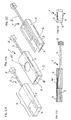
- FIG. 1 schematically in several sub-figures (1A - 1E) shows a preferred embodiment of the analytical tool.
- the lancet (2) is shown.
- This contains a lancet needle (3), which is embedded in a lancet body (4).
- the lancet body (4) consists of a hard plastic part (5) and a part of elastic material (6).
- a capillary gap (7) is incorporated, which serves the sample liquid transport.
- At the rear end of the lancet needle (3) has a thickening (8) is attached, which serves to ensure that the lancet needle in the lancing device or in the lancing device can be easily grasped.
- FIG. 1B is the finished analytical tool (1) shown.
- a strip-shaped test element (9) is applied, which contains a test field (10). This is accessible via the capillary gap (7) for the sample liquid.
- Figure 1C is the analytical tool (1) shown in perspective from the bottom.
- the hard plastic part (5) of the lancet body (4) touches and holds the lancet needle (3) only in the area of two webs.
- the tip of the lancet needle (3) is embedded in the elastic material (6) of the lancet body.
- FIG. 1D is a longitudinal section through the analytical tool (1) shown.
- Figure 1E is a front view of the analytical tool (1) to see.
- FIG. 2 In several subfigures (FIGS. 2A-2E), a further preferred embodiment of the analytical aid according to the invention is shown.
- the lancet (2) of the analytical tool (1) is seen in perspective from above.
- the lancet (2) consists of a lancet needle (3), which is embedded in a lancet body (4). This consists of a hard plastic part (5) and a part of elastic material (6).
- a thickening (8) is attached to the rear end of the lancet needle (3), which serves for gripping the lancet needle (3) by a lancing instrument.
- FIG. 1 Unlike in FIG. 1 contains the analytical tool in Figure (2 ) a capillary gap not in the lancet body (4), but as part of the test element (9).
- FIG. 2B the ready assembled analytical aid (1) is shown, in which a test element (9) is fastened on the lancet body (4).
- This test element contains a capillary gap (7), which makes the test field (10) accessible to a blood sample.
- FIG. 2C is a perspective view of the analytical aid (1) according to FIG. 2B pictured from below.
- the lancet needle (3) is only connected by webs with the hard plastic part (5) of the lancet body (4).
- the needle tip of the lancet needle (3) is completely embedded in the elastic material (6) of the lancet body.
- FIG. 2D illustrates a longitudinal section of the analytical device (1) according to FIG. 2B in this Figure 2E is a corresponding frontal view of the analytical device (1) according to FIG. 2B to see.
- the Figures 2D and 2E make it clear that the capillary gap (7) is part of the test element (9).
- FIG. 3 In several subfigures (FIGS. 3A-3E), another preferred embodiment of the analytical aid (1) of the invention is shown.
- FIG. 3 Similar to the embodiment according to FIG. 1 contains the embodiment according to FIG. 3 a capillary gap (7) as part of the hard plastic part (5) of the lancet body (4). Only the position of the capillary gap (7) and the position of the test element (9) differ from that of the embodiment according to FIG. 1 While in the embodiment according to FIG. 1 Test element (9) and capillary gap (7) are arranged on one of the large boundary surfaces of the lancet body (4), these elements are in the embodiment according to FIG. 3 arranged laterally on one of the narrow boundary surfaces of the lancet body (7). Function and structure of the embodiment according to FIG. 3 otherwise corresponds substantially to what is for the embodiment according to FIG. 1 has been described.
- the FIGS. 3A to 3E correspond to the Figures 1A to 1E ,
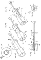
- FIG. 4 is in several subfigures ( FIGS. 4A-4F ) shows a further preferred embodiment of the analytical aid (1) according to the invention.
- the capillary gap (7) was either part of the hard plastic part (5) of the lancet body (4) or part of the test element (9) is in the embodiment according to FIG. 4 the capillary gap (7) is accommodated partly in the elastic material (6) of the lancet body (4) and partly in the test element (9).
- the capillary gap (7) can be divided into three sections (7, 7A and 7B). divide. These are in contact with each other, which allows a sample liquid transport.
- the embodiment according to FIG. 4 from a lancet (2), which contains a lancet needle (3) which is partially surrounded by a lancet body (4).
- the lancet body (4) consists of a hard plastic part (5) and an elastic material (6), which in particular surrounds the lancet needle tip (cf. FIG. 4A ).
- At the rear end of the lancet needle (3) has a thickening (8) attached to the lancet needle, which in turn is to allow the gripping of the needle (3) by a lancing device.
- test element (9) which contains a test field (10).
- test field (10) is available via a system of capillary channels (7, 7A, 7B) for sample liquid.
- the outlet opening of the lancet needle (3) is closed in this embodiment by a closure film (11).
- a closure film (11) When using the lancet either the sealing foil (11) can be punctured by the lancet needle (3) or the sealing foil (11) is manually removed before use.
- Figure 4E shows a frontal view of the outlet opening of the lancet of the analytical device (1).
- FIG. 4F shows an enlarged view of the detail of the frontal view marked X in FIG Figure 4E ,
- the elastic material (6) of the lancet body (4) 4 capillary channels (7) are provided, which allow a sample transport to the test element (9).
- a thickening (8) is provided, which is of central importance for the lancing movement.
- This thickening (8) is formed so that a lancing device can be coupled to it.
- the drive takes over both the forward and the return movement of the needle (3).
- a drive coupling is conceivable in which a plunger takes over the forward movement. The return movement then takes place via a spring, which is compressed during the forward movement and then relaxed again.
- the thickening (8) on the needle (3) is important here as one of the contact points for the spring.
- This spring can either be part of the disposable or part of the device or a cassette or a magazine.
- the thickening (8) can be realized for example by an attached part of plastic or metal. Also, a mechanical deformation (crushing, bending) of the needle (3) to produce a thickening (8) is conceivable.
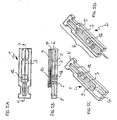
- FIG. 5 is in several sub-figures (5A - 5D) to see a further embodiment of the invention.
- the thickening (11) of the lancet needle (3) is not at the rear end of the lancet needle (3), but in the region of the needle center.
- the thickening is located inside the lancet body (4).
- a useful drive mechanism can only access the side of the disposable. This solution has the advantage of a particularly compact and robust Dispos.
- the analytical aid (1) otherwise corresponds substantially to the embodiment according to FIG. 2 ,
- FIG. 5A is a view of the analytical tool (1) seen from below.
- FIG. 5B FIG. 4 illustrates a sectional view through the longitudinal axis of the analytical device (1).
- FIG. FIG. 5C is a perspective view of the underside of the analytical device (1), in which the lancet needle (3) is in a position in which it is before or after the lancing process. The tip of the lancet needle is embedded in the elastic material (6) of the lancet body.
- FIG. 5D is - illustrated for clarity without test element (9) and elastic material (6) - the lancet (2) in the position in which the lancet needle (3) is present during the lancing process. The lancet needle tip protrudes out of the contours of the lancet body (4).
- FIG. 6 is greatly simplified schematically reproduced as the production of analytical tools (1) according to FIG. 2 made of band material.
- lancets (12) combined to form a band or belt (13) and test elements (9) combined to form a band or belt (14) are provided in the area A.
- region B the two bands are combined and the test element band (14) glued to the lancet band (13).
- region C the bands connected to one another are separated into individual analytical aids (1), for example by cutting off the terminal auxiliaries (1).
Abstract
Description
Die Erfindung betrifft ein Verfahren zur Herstellung eines analytischen Hilfsmittels, welches eine Lanzette und ein analytisches Testelement enthält.The invention relates to a method for the production of an analytical aid which contains a lancet and an analytical test element.
Die Untersuchung von Blutproben ermöglicht in der klinischen Diagnostik das frühzeitige und zuverlässige Erkennen von pathologischen Zuständen sowie die gezielte und fundierte Kontrolle von Körperzuständen. Die medizinische Blutdiagnostik setzt stets die Gewinnung einer Blutprobe des zu untersuchenden Individuums voraus. Während in Kliniken und bei niedergelassenen Ärzten oftmals durch eine Venenpunktion mehrere Milliliter Blut einer zu untersuchenden Person für die Analyse gewonnen werden, um damit eine Vielzahl von Labortests durchführen zu lassen, reichen für einzelne Analysen, die gezielt auf einen Parameter gerichtet sind, heutzutage oftmals wenige Mikroliter bis hin zu weniger als einem Mikroliter Blut aus. Solch geringe Blutmengen erfordern keine aufwendige und schmerzhafte Venenpunktion. Vielmehr genügt es hier, zur Blutgewinnung durch die Haut z. B. in die Fingerbeere oder das Ohrläppchen der zu untersuchenden Person mit Hilfe einer sterilen, scharfen Lanzette zu stoßen, um so einige wenige Mikroliter Blut oder weniger für die Analyse zu gewinnen. Insbesondere eignet sich diese Methode, wenn die Analyse der Blutprobe unmittelbar nach der Blutgewinnung durchgeführt werden kann.The examination of blood samples in clinical diagnostics allows the early and reliable detection of pathological conditions as well as the targeted and well-founded control of body conditions. Medical blood diagnostics always requires obtaining a blood sample from the individual to be examined. While clinicians and general practitioners often use venipuncture to extract several milliliters of blood from a person to be examined for analysis, and to run a variety of laboratory tests, nowadays only a few of those targeted for one parameter are often sufficient Microliters down to less than a microliter of blood. Such small amounts of blood do not require elaborate and painful venipuncture. Rather, it is sufficient here for blood through the skin z. B. in the fingertip or earlobe of the person to be examined using a sterile, sharp lancet, so as to win a few microliters of blood or less for analysis. In particular, this method is suitable if the analysis of the blood sample can be carried out immediately after obtaining the blood.
Vor allem im Bereich des sogenannten "Home-Monitoring", also dort, wo medizinische Laien selbst einfache Analysen des Bluts durchführen, und dort insbesondere für die regelmäßige, mehrmals täglich durchzuführende Blutgewinnung durch Diabetiker für die Kontrolle der Blutglucosekonzentration, werden Lanzetten und dazu passende Geräte (sogenannte Blutentnahmegeräte, Blutlanzettenvorrichtungen oder - wie sie im Folgenden genannt werden sollen - Stechhilfen), angeboten, die eine möglichst schmerzarme und reproduzierbare Blutgewinnung ermöglichen. Zudem soll die Verwendung von Lanzetten mit Stechhilfen die psychologische Schwelle beim Stechen des eigenen Körpers senken, was vor allem für Kinder, die an Diabetes erkrankt sind und auf regelmäßige Blutglucosetests angewiesen sind, von besonderer Bedeutung ist. Als Beispiele für Lanzetten und Stechhilfen seien die kommerziell erhältlichen Geräte (Stechhilfen) und Lanzetten Glucolet® der Bayer AG und Softclix® der Roche Diagnostics GmbH genannt. Solche Lanzetten und Geräte (Stechhilfen) sind z. B. Gegenstand von
Die eigenhändige Blutzuckerbestimmung (das sogenannte "Home Monitoring") ist heute eine weltweit verbreitete Methode in der Diabetes-Kontrolle. Blutzuckergeräte im Stand der Technik wie z. B. Accu-Chek Sensor (von Roche Diagnostics) bestehen aus einem Messgerät, in das ein Testelement (Teststreifen, Sensor) eingeführt wird. Der Teststreifen wird mit einem Blutstropfen in Kontakt gebracht, der zuvor mittels einer Stechhilfe aus der Fingerbeere gewonnen wurde. Die zahlreichen Systemkomponenten (Lanzette, Stechhilfe, Teststreifen und Messgerät) benötigen viel Platz und bedingen ein relativ komplexes Handling. Inzwischen gibt es auch Systeme mit einem höheren Grad der Integration und damit einer einfacheren Handhabung. Hierzu gehören beispielsweise das AccuChek Compact (von Roche Diagnostics), das Glucometer Dex (von Bayer Diagnostics) sowie das Soft-Sense (von Medisense). Bei den beiden erstgenannten Systemen werden die Teststreifen im Messgerät magaziniert und für die Messung zur Verfügung gestellt.Autonomous blood glucose monitoring (so-called "home monitoring") is today a worldwide used method in diabetes control. Blood sugar devices in the prior art such. B. Accu-Chek Sensor (from Roche Diagnostics) consist of a meter into which a test element (test strip, sensor) is inserted. The test strip is brought into contact with a drop of blood previously obtained by means of a finger-stick lancing device. The numerous system components (lancet, lancing device, test strips and measuring device) require a lot of space and cause a relatively complex handling. Meanwhile, there are also systems with a higher degree of integration and thus a simpler handling. These include, for example, the AccuChek Compact (from Roche Diagnostics), the Glucometer Dex (from Bayer Diagnostics) and the Soft-Sense (from Medisense). In the first two systems, the test strips are stored in the measuring device and made available for the measurement.
Ein nächster Schritt der Miniaturisierung ist beispielsweise durch die Integration von mehreren Funktionen bzw. Funktionselementen in einem einzigen analytischen Hilfsmittel (Disposable) zu erreichen. Durch geeignete Kombination von Stechvorgang und sensorischer Analytkonzentrations-Erfassung auf einem Teststreifen lässt sich beispielsweise der Bedienablauf deutlich vereinfachen. Hierfür gibt es im Stand der Technik folgende Beispiele:A next step in miniaturization can be achieved, for example, by integrating multiple functions or functional elements in a single analytical tool (disposable). By a suitable combination of lancing process and sensory analyte concentration detection on a test strip, for example, the operating procedure can be significantly simplified. For this purpose, there are the following examples in the prior art:
In
Ein zentrales Problem der Blutgewinnung mit einem sogenannten "integrierten Disposable" (bei dem Lanzette und Testelement miteinander verbunden sind bzw. einen Einheit bilden) ist die Tatsache, dass nach einem Einstich das Kapillarblut meist nicht selbsttätig aus der Wunde austritt. Durch direkten Kontakt eines Disposables mit der Wundöffnung wird dieser negative Effekt noch verstärkt. Nach einem Einstich muss der Blutstropfen aktiv an die Hautoberfläche befördert werden, indem man beispielsweise die Wunde mechanisch öffnet und/oder einen leichten Druck auf das Gewebe rund um den Wundbereich ausübt (beispielsweise durch einfaches "Finger melken"). Das Anlegen von Vakuum kann diesen Vorgang sinnvoll unterstützen.A central problem of obtaining blood with a so-called "integrated disposable" (in the lancet and test element are connected or form a unit) is the fact that after a puncture, the capillary blood usually does not emerge automatically from the wound. Direct contact of a disposable with the wound opening further exacerbates this negative effect. After a puncture, the drop of blood must be actively transported to the skin surface, for example, by mechanically opening the wound and / or exerting light pressure on the tissue around the wound area (for example, by simply "milking the finger"). The application of vacuum can meaningfully support this process.
Wie Untersuchungen im Labor gezeigt haben, ist es vorteilhaft, dass die Wundöffnung für den Zeitraum der Blutgewinnung freibleibt. Diese Tatsache bedingt jedoch einen komplizierten Bewegungsablauf beim Dispo, da eine sehr schnelle Stechbewegung und eine langsame Blutaufnahmebewegung mit einer Wartezeit im System zu realisieren sind. Hierzu sind nur wenige der im Stand der Technik vorgeschlagenen Dispo-Konzepte geeignet.As studies in the laboratory have shown, it is advantageous that the wound opening remains free for the period of blood production. However, this fact requires a complicated movement during dispensing, since a very fast puncturing and a slow blood collection movement with a waiting time in the system can be realized. For this purpose, only a few of the proposed in the prior art Dispo concepts are suitable.
Insbesondere eine starre, herausragende Lanzettenspitze kann beim Aufnehmen des Blutstropfens zu ungewollten Verletzungen führen. Eine relativ zum Disposable bewegliche Stechvorrichtung ist somit zu bevorzugen. Diese Anforderung in Kombination mit den im Stand der Technik bekannten Dispos führt jedoch zu einer aufwendigen und damit auch teuren Dispoausführung.In particular, a rigid, protruding lancet tip can lead to unwanted injuries when receiving the blood drop. A relative to Disposable movable lancing device is thus preferable. However, this requirement in combination with the Dispos known in the art leads to a complex and therefore expensive Dispoausführung.
Ein weiteres Manko bekannter Dispos ist die Sicherstellung der Lanzettensterilität für den Zeitraum der Aufbrauchfrist. Im Stand der Technik bekannt ist der Spitzenschutz durch eine Kappe, die vor Gebrauch manuell entfernt wird. Die Automatisierung von Blutzuckermessungen wird jedoch durch solch eine Kappe erschwert. Bisher beschriebene Konzepte, die eine automatische Blutzuckerbestimmung mit einem integrierten Disposable prinzipiell ermöglichen würden, weisen den Nachteil auf, dass eine latente Verschmutzungsgefahr der Lanzettennadelspitze vorhanden ist. Bestandteile des Testfeldes (Chemiekalien, biologische Bestandteile, Klebstoffe etc.) können durch die Luft oder über Oberflächen innerhalb des Dispos wandern. Eine anfänglich durchgeführte Sterilisation der Nadelspitze ohne weitere schützende Maßnahmen ist somit keinesfalls ausreichend, um die Anforderungen an ein steriles Medizinprodukt einzuhalten.Another shortcoming of known disposables is the guarantee of lancet sterility for the period of the exhaustion period. Known in the art is the tip guard by a cap which is manually removed prior to use. However, the automation of blood glucose measurements is hampered by such a cap. Previously described concepts that would allow an automatic blood glucose determination with an integrated disposable in principle, have the disadvantage that a latent risk of contamination of the lancet needle tip is present. Components of the test field (chemicals, biological constituents, adhesives, etc.) may migrate through the air or over surfaces within the device. An initial sterilization of the needle tip without further protective measures is thus by no means sufficient to meet the requirements for a sterile medical device.
Die Lanzetten des Standes der Technik weisen meist eine metallene Lanzettennadel mit einer Spitze auf, die gegebenenfalls angeschliffen sein kann. Zur leichteren Handhabung der Lanzette und gegebenenfalls zu ihrer Befestigung in einer Stechhilfe ist bei vielen Ausführungsformen meist an die Lanzettennadel ein Kunststofflanzettenkörper aus einem starren, spritzgußfähigen Material angespritzt. Die Spitze der Lanzettennadel ist - im unbenutzten Zustand - zur Sicherstellung ihrer Sterilität von einer Schutzhülle umgeben. Diese besteht in der Regel aus dem selben starren Material wie der eigentliche Lanzettenkörper und bildet meist mit diesem eine Einheit. Die Schutzhülle kann vor der Benutzung der Lanzette vom Lanzettenkörper getrennt und von der Spitze der Lanzettennadel abgenommen werden. Zwischen Lanzettenkörper und Schutzhülle befindet sich zu diesem Zweck meist eine Sollbruchstelle. Nach der Benutzung der Lanzette liegt die Spitze der Lanzettennadel ungeschützt vor und stellt somit eine potentielle Verletzungsquelle für den Benutzer und eventuell andere Personen dar.The lancets of the prior art usually have a metal lancet needle with a tip, which may possibly be ground. For easier handling of the lancet and possibly for its attachment in a lancing device, in many embodiments, a plastic lancet body of a rigid, injection-moldable material is usually molded onto the lancet needle. The tip of the lancet needle is - when not in use - surrounded by a protective cover to ensure its sterility. This usually consists of the same rigid material as the actual lancet body and usually forms a unit with this. The protective sheath may be separated from the lancet body prior to use of the lancet and removed from the tip of the lancet needle. Between lancet body and protective cover is usually a breaking point for this purpose. After using the lancet, the tip of the lancet needle is unprotected and thus presents a potential source of injury to the user and possibly other persons.
Die Aufgabe der vorliegenden Erfindung war es daher, die Nachteile des Standes der Technik, insbesondere die eingangs erwähnten Nachteile zu beseitigen. Insbesondere war es die Aufgabe der vorliegenden Erfindung ein Verfahren zur Herstellung analytischer Hilfsmittel (oder synonym dazu: "Disposables", kurz: "Dispos") zur Verfügung zu stellen, die die Nachteile des Standes der Technik nicht zeigen. Ganz besonders sollte die Sicherstellung der Lanzettensterilität für den Zeitraum der Aufbrauchfrist durch das erfindungsgemäße Dispo bei gleichzeitiger Integration von Lanzette und Testelement (Teststreifen, Sensor) gewährt werden. Weiterhin ist es die Aufgabe der vorliegenden Erfindung, ein Verfahren zur Herstellung analytischer Hilfsmittel mit Lanzetten bereitzustellen, bei denen zumindest die Lanzettennadelspitze im unbenutzten Zustand bis unmittelbar vor der Benutzung steril, das heißt keimfrei, gehalten wird und im benutzten Zustand hygienisch aufbewahrt werden kann. Idealerweise sollte diese Aufgabe gelöst werden, ohne daß der Benutzer für die hygienische Aufbewahrung separate Maßnahmen zu ergreifen hat. Zudem sollte der Benutzer vor unbeabsichtigter Verletzung mit der Lanzette, insbesondere der benutzten Lanzette geschützt sein. Schließlich sollte vorzugsweise ein einfacher Probentransfer von der Stelle der Blutgewinnung zur Stelle der Blutuntersuchung möglich sein.The object of the present invention was therefore to eliminate the disadvantages of the prior art, in particular the disadvantages mentioned above. In particular, it was the object of the present invention to provide a process for the production of analytical aids (or synonymously: "disposables", in short "disposables"), which do not show the disadvantages of the prior art. In particular, the guarantee of lancet sterility for the period of the exhaustion period should be granted by the inventive Dispo with simultaneous integration of lancet and test element (test strip, sensor). Furthermore, it is the object of the present invention to provide a method for producing analytical aids with lancets, in which at least the lancet needle tip in the unused state until immediately before use sterile, that is kept germ-free, and can be stored hygienically in the used state. Ideally, this task should be solved without the user having to take separate measures for hygienic storage. In addition, the user should be protected against unintentional injury to the lancet, especially the lancet used. Finally, preferably a simple sample transfer from the site of blood collection to the site of the blood test should be possible.
Diese Aufgabe wird durch den Gegenstand der Erfindung, wie er in dem unabhängigen Patentanspruch charakterisiert wird, gelöst. Bevorzugte Ausführungsformen sind Gegenstand der abhängigen Ansprüche.This object is solved by the subject matter of the invention as characterized in the independent claim. Preferred embodiments are subject of the dependent claims.
Ein erster Gegenstand der Erfindung ist ein Verfahren zur Herstellung eines analytischen Hilfsmittels, das eine Lanzette enthält. Die Lanzette weist als wesentliche Bestandteile eine Lanzettennadel mit einer Spitze und einen Lanzettenkörper auf, der die Lanzettennadel zumindest im Bereich der Spitze vollständig umgibt. Die Lanzettennadel ist dabei relativ zum Lanzettenkörper verschiebbar. Der Lanzettenkörper besteht zumindest im Bereich der Spitze der Lanzettennadel aus einem elastischen Material, in das die Spitze der Lanzettennadel eingebettet ist. Das analytische Hilfsmittel enthält weiterhin ein analytisches Testelement, das fest mit dem Lanzettenkörper verbunden ist.A first object of the invention is a process for the preparation of an analytical aid containing a lancet. The lancet has as essential components a lancet needle with a tip and a lancet body, which completely surrounds the lancet needle at least in the region of the tip. The lancet needle is displaceable relative to the lancet body. The lancet body consists at least in the region of the tip of the lancet needle of an elastic material in which the tip of the lancet needle is embedded. The analytical aid further contains an analytical test element which is firmly connected to the lancet body.
Ein weiterer Gegenstand der Erfindung ist ein Verfahren zur Herstellung eines weiteren analytischen Hilfsmittels das eine Lanzette enthält. Die Lanzette umfasst dabei eine Lanzettennadel mit einer Spitze und einen Lanzettenkörper, der im Bereich der Spitze der Lanzettennadel als Hohlkörper ausgebildet ist und der die Spitze der Lanzettennadel umgibt. Die Lanzettennadel ist auch hier relativ zum Lanzettenkörper verschiebbar. Der Hohlkörper besteht zumindest teilweise aus einem elastischen Material, das von der Spitze der Lanzettennadel beim Stechvorgang durchstoßen werden kann und das sich gegebenenfalls nach dem Zurückziehen der Spitze der Lanzettennadel in den Hohlkörper wieder verschließt. Das analytische Hilfsmittel enthält weiterhin ein analytisches Testelement, das fest mit dem Lanzettenkörper verbunden ist.Another object of the invention is a method for producing a further analytical aid containing a lancet. The lancet in this case comprises a lancet needle with a tip and a lancet body which is formed in the region of the tip of the lancet needle as a hollow body and which surrounds the tip of the lancet needle. The lancet needle is also displaceable relative to the lancet body here. The hollow body consists at least partially of an elastic material which can be pierced by the tip of the lancet needle during the lancing process and which optionally closes again after retraction of the tip of the lancet needle into the hollow body. The analytical aid further contains an analytical test element which is firmly connected to the lancet body.
Die erfindungsgemäße Lösung besteht vorzugsweise aus einem Verfahren zur Herstellung eines miniaturisierten Dispo, bei dem die drei Funktionen Stechen, Bluttransfer von der durch das Stechen erzeugten Wunde zum Testelement, und Sensorik in einem Teil zusammengefasst sind.The solution according to the invention preferably consists of a method for producing a miniaturized dispo, in which the three functions stinging, blood transfer from the wound created by the stinging to the test element, and sensor technology are combined in one part.
Der Grundkörper des erfindungsgemäßen analytischen Hilfsmittels besteht aus einem starren Kunststoffkörper, dessen äußere Form vorzugsweise zum Zwecke der Halterung in einem Gerät entsprechend angepasst ist. In diesem Kunststoff wird eine Lanzettennadel derart eingebettet, dass ihre Spitze vorzugsweise nicht über die Vorderkante des Grundkörpers herausragt. Der Grundkörper kann daher auch als Lanzettenkörper bezeichnet werden. Der Grundköper besitzt in einer bevorzugten Ausführungsform Stege, die zur Fixierung der Nadel im Grundkörper und zur Führung während der Stechbewegung dienen.Vorzugsweise ist der überwiegende Teil der Nadel jedoch nicht mit dem Grundkörper verbunden, um die Reibungskräfte bei der Stechbewegung zu minimieren. Bevorzugt werden die Kontaktflächen zwischen Nadel und Lanzettenkörper minimiert und geeignet vorbehandelt, beispielsweise silikonisiert.The main body of the analytical aid according to the invention consists of a rigid plastic body whose outer shape is preferably adapted accordingly for the purpose of mounting in a device. In this plastic, a lancet needle is embedded such that its tip preferably does not protrude beyond the front edge of the body. The main body can therefore also be referred to as a lancet body. The base body in a preferred embodiment has webs which serve to fix the needle in the body and to guide it during the piercing movement. Preferably, however, the majority of the needle is not connected to the body to minimize the frictional forces in the piercing movement. The contact surfaces between the needle and the lancet body are preferably minimized and suitably pretreated, for example siliconized.
Die erfindungsgemäßen Lanzetten sind vorzugsweise für den einmaligen Gebrauch konzipiert und können daher auch als Einweg-Blutlanzetten oder Wegwerf-Blutlanzetten bezeichnet werden. Die Lanzette der Erfindung beinhaltet eine Nadel (Lanzettennadel) mit einer Spitze. Die Nadel ist in der Regel mehrere Millimeter (mm) bis wenige Zentimeter (cm) lang und weist eine längliche Gestalt auf. Typischerweise besitzen Nadeln eine zylindrische Gestalt, da diese Nadelform besonders gut herstellbar ist; es sind jedoch auch Nadelformen mit abweichender Formgebung möglich. Der Spitzenbereich der Nadel beinhaltet die Nadelspitze, die beim bestimmungsgemäßen Gebrauch der Lanzette in Gewebe eingestochen wird. Die Spitze der Lanzettennadel ist folglich der Teil der Lanzette, der mit der Haut des zu stechenden Individuums in Berührung kommt, diese ggf. verletzt und so den Ausfluß einer Körperflüssigkeit, insbesondere Blut oder interstitieller Flüssigkeit, verursacht.The lancets according to the invention are preferably designed for single use and can therefore also be referred to as disposable blood lancets or disposable blood lancets. The lancet of the invention includes a needle (lancet needle) with a tip. The needle is usually several millimeters (mm) to a few centimeters (cm) long and has an elongated shape. Typically, needles have a cylindrical shape, since this needle shape is particularly easy to produce; However, there are also needle shapes with different shapes possible. The tip region of the needle includes the needle tip, which is inserted into tissue during proper use of the lancet. The tip of the lancet needle is thus the part of the lancet which comes into contact with the skin of the individual to be stung, possibly injuring the latter and thus causing the outflow of a body fluid, in particular blood or interstitial fluid.
Die Spitze der Lanzettennadel kann beispielsweise rotationssymmetrisch sein, wie dies im Allgemeinen bei Stecknadeln der Fall ist. Es hat sich jedoch als vorteilhaft herausgestellt, wenn man an der Nadelspitze einen oder mehrere Schliffe anbringt. Die hierbei entstehenden, zur Längsachse der Nadel geneigten, in einer Spitze zulaufenden Kanten dienen beim Einstich als scharfe Schneide und gestalten den Einstichvorgang schmerzärmer, als dies mit rotationssymmetrischen Nadeln der Fall ist.The tip of the lancet needle, for example, be rotationally symmetric, as is generally the case with pins. However, it has proven to be advantageous if one attaches to the needle tip one or more cuts. The resulting, inclined to the longitudinal axis of the needle, tapering in a peak edges are used during piercing as a sharp edge and make the puncture pain less than is the case with rotationally symmetric needles.
Die Lanzettennadel der erfindungsgemäßen Lanzette ist aus einem Material gefertigt, das ausreichend hart ist, um eine mechanische Beanspruchung während des Einstichvorgangs, der Bearbeitungsschritte oder eventuell sonstige auftretende Beanspruchungen ohne Deformation zu überstehen. Weiterhin muß das Material so beschaffen sein, daß während des Einstichvorgangs keine Partikel abbrechen oder sich ablösen. Schließlich muß das Nadelmaterial auch so bearbeitbar sein, daß die Nadelspitze ausreichend spitz und die Kanten der Nadelspitze gegebenenfalls ausreichend scharf geschliffen werden können. Gut geeignete Materialien für die Lanzettennadel sind vor allem Metalle und von diesen insbesondere Edelstähle. Es sind jedoch auch Nadeln aus Silizium, Keramik oder Kunststoffen denkbar. Edelstahlnadeln sind besonders bevorzugt.The lancet needle of the lancet according to the invention is made of a material that is sufficiently hard to mechanical stress during the puncture process, the processing steps or possibly other stresses occurring without deformation to survive. Furthermore, the material must be such that no particles break or peel off during the puncture process. Finally, the needle material must also be machinable so that the needle tip sufficiently sharp and the edges of the needle tip can be ground if necessary sufficiently sharp. Highly suitable materials for the lancet needle are mainly metals and of these, in particular stainless steels. However, also needles made of silicon, ceramic or plastics are conceivable. Stainless steel needles are particularly preferred.
Erfindungsgemäß ist in einer Ausführungsform zumindest die Spitze der Lanzettennadel der erfindungsgemäßen Lanzette vom Lanzettenkörper umgeben. Wesentlich ist dabei, daß der Lanzettenkörper im Bereich der Spitze der Lanzettennadel aus einem elastischen Material besteht. Zumindest die Spitze der Lanzettennadel ist von diesem elastischen Material allseitig vollständig umgeben, das heißt in dieses eingebettet, und so von der Umgebung abgeschlossen. Das elastische Material des Lanzettenkörpers, welches in unterschiedlichen Ausführungsformen den Lanzettenkörper vollständig oder nur teilweise bilden kann, zeichnet sich dadurch aus, daß es weich, verformbar und von der Lanzettennadel mit ihrer Spitze durchstoßbar ist, ohne die Spitze zu verletzen. Beim Stechvorgang wird die Lanzettennadel entlang ihrer Längsachse relativ zum Lanzettenkörper bewegt und tritt mit ihrer Spitze aus dem Lanzettenkörper aus, um so zur Blutgewinnung in die Haut des zu untersuchenden Individuums einstechen zu können. Eine wichtige und erfindungsgemäß bevorzugte Eigenschaft ist ferner, daß sich das elastische Material gegebenenfalls beim Zurückziehen der Lanzettennadel in den Lanzettenkörper wieder dicht um die Spitze der Lanzettennadel verschließt. Nach dem Stechvorgang kann die Lanzettennadel in einer bevorzugten Ausführungsform in Umkehrung der Bewegung beim Stechvorgang in ihre Ausgangslage relativ zum Lanzettenkörper gebracht werden, in der die Spitze wieder allseitig vollständig vom elastischen Material des Lanzettenkörpers umschlossen ist.According to the invention, in one embodiment at least the tip of the lancet needle of the lancet according to the invention is surrounded by the lancet body. It is essential that the lancet body in the region of the tip of the lancet needle consists of an elastic material. At least the tip of the lancet needle is completely surrounded by this elastic material on all sides, that is embedded in this, and so completed by the environment. The elastic material of the lancet body, which can form the lancet body completely or only partially in different embodiments, is characterized in that it is soft, deformable and can be pierced by the lancet needle with its tip, without damaging the tip. During the lancing process, the lancet needle is moved along its longitudinal axis relative to the lancet body and emerges with its tip from the lancet body so as to be able to pierce the skin of the individual to be examined in order to obtain blood. An important and preferred feature according to the invention is further that the elastic material optionally closes tightly around the tip of the lancet needle when retracting the lancet needle into the lancet body. After the lancing process, in a preferred embodiment, the lancet needle can be brought into its initial position relative to the lancet body in a reversal of the movement during the lancing process, in which the tip is again completely surrounded on all sides by the elastic material of the lancet body.
Das elastische Material des Lanzettenkörpers, welches die Spitze der Lanzettennadel vollständig umschließt, gewährleistet die Sterilität der Lanzettennadelspitze vor deren Benutzung, vorzugsweise bis unmittelbar vor deren Benutzung, und sorgt gegebenenfalls für ein hygienisches Umschließen der Lanzettennadelspitze nach deren Benutzung. Der Begriff ,hygienisches Umschließen' ist so zu interpretieren, daß das unter Umständen nach dem Stich an der Nadel anhaftende biologische Material (Gewebe, Körperflüssigkeit) im Wesentlichen vom elastischen Material eingekapselt wird. Insbesondere Keime und infektiöses Material können somit nicht oder nur stark reduziert an die Außenwelt gelangen. Das elastische Material ist folglich keimdicht für das Eindringen oder Entweichen von Keimen, je nach dem, ob die Lanzettennadel unbenutzt oder benutzt ist. Zudem stellt das elastische Material einen mechanischen Schutz für die Lanzettennadelspitze dar und verhindert so auch ein unbeabsichtigtes Verletzen an der Lanzettennadelspitze.The elastic material of the lancet body, which completely surrounds the tip of the lancet needle, ensures the sterility of the lancet needle tip prior to use, preferably until just prior to use, and optionally provides hygienic enclosure of the lancet needle tip after use. The term 'hygienic enclosing' is to be interpreted as meaning that the biological material (tissue, body fluid) adhering to the needle after the stitch is substantially encapsulated by the elastic material. In particular, germs and infectious material can not reach the outside world, or only greatly reduced. The elastic material is thus germ-proof for the penetration or escape of germs, according to which whether the lancet needle is unused or used. In addition, the elastic material provides mechanical protection for the lancet needle tip and thus also prevents unintentional injury to the lancet needle tip.
Als elastisches Material für den Lanzettenkörper der vorliegenden Erfindung haben sich Gummi, Kautschuk, Silikon, Elastomere und insbesondere thermoplastische Elastomere als geeignet herausgestellt. Diese weisen die für die vorliegende Erfindung wesentlichen Eigenschaften auf: sie sind weich, verformbar, von der Lanzettennadel zu durchstoßen, ohne die Spitze zu verletzen, und schließen sich dicht um die benutzte Lanzettennadelspitze. Des weiteren können Sie für Spritzgußprozesse verwendet werden, die eine Massenfertigung von Lanzetten in großen Stückzahlen ermöglichen.As the elastic material for the lancet body of the present invention, rubber, rubber, silicone, elastomers and especially thermoplastic elastomers have been found to be suitable. These have the characteristics essential to the present invention: they are soft, deformable, punctured by the lancet needle without damaging the tip, and close tightly around the used lancet needle tip. Furthermore, they can be used for injection molding processes that enable mass production of large numbers of lancets.
Thermoplastische Elastomere, die auch Elastoplaste oder Thermolaste oder thermoplastische Kautschuke genannt werden, besitzen im Idealfall eine Kombination der Gebrauchseigenschaften von Elastomeren und den Verarbeitungseigenschaften von Thermoplasten. Thermoplastische Elastomere sind beispielsweise Styrol-Oligoblock-Copolymere (sogenannte TPE-S), thermoplastische Polyolefine (TPE-O), thermoplastische Polyurethane (TPE-U), thermoplastische Copolyester (TPE-E) und thermoplastische Copolyamide (TPE-A). Insbesondere haben sich beispielsweise thermoplastische Elastomere auf der Basis von Styrol-Ethylen-Butylen-Styrol-Polymeren (SEBS-Polymere, z. B. Evoprene® von Evode Plastics oder Thermolast K von Gummiwerk Kraiburg GmbH) als geeignet erwiesen.Thermoplastic elastomers, which are also called elastoplasts or thermoplastic elastomers or thermoplastic rubbers, ideally have a combination of the performance properties of elastomers and the processing properties of thermoplastics. Thermoplastic elastomers are, for example, styrene-oligoblock copolymers (so-called TPE-S), thermoplastic polyolefins (TPE-O), thermoplastic polyurethanes (TPE-U), thermoplastic copolyesters (TPE-E) and thermoplastic copolyamides (TPE-A). In particular, for example, thermoplastic elastomers based on styrene-ethylene-butylene-styrene polymers (SEBS polymers, eg Evoprene® from Evode Plastics or Thermolast K from Gummiwerk Kraiburg GmbH) have proven to be suitable.
Während des Stechvorgangs wird die Lanzettennadel relativ zum Lanzettenkörper bewegt. Letzterer wird dabei vorzugsweise von der Stechhilfe oder dem Stechgerät in seiner Position fixiert. Die Lanzettennadel kann zum Zwecke ihres Antriebs besonders ausgeformt sein, beispielsweise einen Nadelkopf an dem der Spitze entgegengesetzten Ende besitzen, oder zusätzlich zum Lanzettenkörper, der die Spitze umschließt, einen weiteren Lanzettenkörper aufweisen, der von einem Antriebselement der Stechhilfe ergriffen werden kann. Die Ausformung der Nadel oder der zusätzliche Lanzettenkörper können in geeigneter Weise mit einer entsprechenden Antriebsvorrichtung im Stechgerät (Stechhilfe) wechselwirken. Allgemein können solche Mittel als Verdickung der Nadel bezeichnet werden.During the lancing process, the lancet needle is moved relative to the lancet body. The latter is preferably fixed by the lancing device or the puncturing device in its position. The lancet needle may be specially shaped for the purpose of its drive, for example having a needle head at the tip opposite the tip, or in addition to the lancet body enclosing the tip, having a further lancet body which can be grasped by a drive member of the lancing device. The formation of the needle or the additional lancet body can suitably interact with a corresponding drive device in the lancing device (lancing aid). In general, such means may be referred to as thickening of the needle.
Zur Erzielung des Vorteils, daß die Lanzettennadelspitze vor Gebrauch steril vom elastischen Material des Lanzettenkörpers umschlossen ist, und nach ihrem Gebrauch hygienisch vom elastischen Material umgeben ist, ist es natürlich notwendig, die Lanzettennadel nach ihrem Gebrauch, d. h. nach dem Stechvorgang, weitgehend in ihre ursprüngliche relative Position bezüglich des Lanzettenkörpers enthaltend das elastische Material zu bringen. Dies kann durch geeignete Wechselwirkung mit einer entsprechend angepaßten Stechhilfe erreicht werden. Wichtig ist dabei nur, daß die Lanzettennadelspitze nach ihrer Benutzung wieder vom elastischen Material des Lanzettenkörpers umschlossen ist und so ein unbeabsichtigtes Verletzen an der Nadelspitze verhindert wird.To achieve the advantage that the lancet needle tip is sterile enclosed by the elastic material of the lancet body before use, and is hygienically surrounded by the elastic material after their use, it is of course necessary, the lancet needle after their use, ie after the lancing, largely in their original relative position with respect to the lancet body containing the elastic material to bring. This can be achieved by appropriate interaction with a suitably adapted lancing device. It is important only that the lancet needle tip is again enclosed by the elastic material of the lancet body after use and thus inadvertent injury to the needle tip is prevented.
Zur Erhöhung der Stabilität des elastischen Materials ist es möglich, dieses mit einem steifen Material, beispielsweise einem steifen Kunststoffmaterial, zu verbinden. Das elastische Material kann dabei beispielsweise auf seiner Außenseite, die nicht mit der Spitze der Lanzettennadel in Berührung kommt, mit einer Schicht eines steifen Materials, beispielsweise eines steifen Kunststoffs, stabilisiert sein. Es ist auch möglich, den Lanzettenkörper nur im Bereich der Lanzettennadelspitze aus einem elastischen Material zu fertigen, im übrigen den Lanzettenkörper jedoch aus herkömmlichen, steifen Kunststoffen zu fertigen. Dabei können das elastische Material und das steife Material miteinander verklebt sein oder durch einen Spritzgußprozeß, beispielsweise einen Zweikomponenten-Spritzgußprozeß, miteinander verbunden sein. Das steife Material des Lanzettenkörpers sorgt dabei für eine mechanische Stabilisierung des elastischen Materials während des Stechvorgangs und erleichtert die Fixierung des elastischen Teils des Lanzettenkörpers während des Stechvorgangs durch die Stechhilfe. Das steife Material kann auch Teil des Testelements sein, beispielsweise eines Kapillarspalttestelements wie es in
In einer weiteren Ausführungsform der Erfindung enthält die Lanzette eine Lanzettennadel mit einer Spitze und einen Hohlkörper, der zumindest die Spitze der Lanzettennadel umgibt, wobei die Lanzettennadel im Bereich ihrer Spitze im Hohlkörper beweglich ist und der Hohlkörper zumindest teilweise aus einem elastischen Material besteht, das von der Spitze der Lanzettennadel beim Stechvorgang durchstoßen werden kann und das sich gegebenenfalls nach dem Zurückziehen der Spitze der Lanzettennadel in den Hohlkörper wieder verschließt.In a further embodiment of the invention, the lancet includes a lancet needle with a tip and a hollow body surrounding at least the tip of the lancet needle, wherein the lancet needle is movable in the region of its tip in the hollow body and the hollow body consists at least partially of an elastic material which the tip of the lancet needle can be pierced during the lancing process and that optionally closes again after retraction of the tip of the lancet needle in the hollow body.
Während bei der weiter oben beschriebenen Lanzette gemäß der ersten Ausführungsform die Lanzettennadel zur Gewährung der Sterilität vor Benutzung und der hygienischen Abgeschirmtheit nach der Benutzung im Bereich ihrer Spitze allseitig vollständig und somit ohne verbleibenden Hohlraum um die Spitze von einem elastischen Material umgeben ist, welches die Lanzettennadelspitze in sich einbettet, ist bei der jetzt beschriebenen zweiten Ausführungsform die Spitze der Lanzettennadel von einem allseits geschlossenen Hohlkörper umgeben. Vorteilhafterweise ist dieser Hohlkörper in den Bereichen, die nicht mit der Spitze der Lanzettennadel in Berührung kommen, aus einem steifen, vorzugsweise spritzgußfähigen Material gefertigt. Erfindungswesentlich ist, daß der Hohlkörper in dem Bereich, in dem er beim Stechvorgang von der Lanzettennadelspitze durchstoßen wird, aus einem elastischen Material besteht.While in the lancet according to the first embodiment described above, according to the first embodiment, the lancet needle for giving the sterility before use and the hygienic shielding after use is completely surrounded on the side of its tip and thus without any remaining cavity around the tip of an elastic material containing the lancet needle tip embedded in itself, in the second embodiment now described, the tip of the lancet needle is surrounded by a hollow body closed on all sides. Advantageously, this hollow body is made of a stiff, preferably injection-moldable material in the areas which do not come into contact with the tip of the lancet needle. Essential to the invention is that the hollow body in the area in which he pierced by the lancet needle tip during the lancing process, consists of an elastic material.
Beim Stechvorgang wird die Lanzettennadel relativ zum Hohlkörper, der den Lanzettenkörper darstellt, bewegt. Halterung und Antrieb der Lanzettennadel und Fixierung des Lanzettenkörpers können, wie oben beschrieben, durch geeignete konstruktive Maßnahmen in der Stechhilfe realisiert werden.During the lancing process, the lancet needle is moved relative to the hollow body, which represents the lancet body. Holder and drive of the lancet needle and fixation of the lancet body can, as described above, be realized by appropriate design measures in the lancing device.
Das elastische Material, welches einen Teil des hohlen Lanzettenkörpers ausmacht, wird beim Stechvorgang von der Lanzettennadelspitze durchstoßen und verschließt sich gegebenenfalls nach dem Zurückziehen der Lanzettennadelspitze in den Hohlkörper wieder und dichtet so den Hohlkörper ab. Die Lanzettennadelspitze ist somit bis unmittelbar vor Gebrauch steril im Hohlkörper versiegelt und wird nach Gebrauch hygienisch in ihm eingeschlossen.The elastic material, which constitutes part of the hollow lancet body, is punctured by the lancet needle tip during the lancing process and optionally closes again after the retraction of the lancet needle tip into the hollow body, thereby sealing off the hollow body. The lancet needle tip is thus sealed until immediately before use sterile in the hollow body and is hygienically enclosed in it after use.
Die Lanzette dieser Ausführungsform kann ebenso wie die Lanzette des oben beschriebenen alternativen Erfindungsgegenstands neben dem Lanzettenkörper, der die Spitze der Lanzettennadel umschließt, einen weiteren Lanzettenkörper aufweisen, der im Zusammenspiel mit geeigneten Elementen einer Stechhilfe während des Stechvorgangs mit diesen wechselwirkt. Ebenso kann die Lanzettennadel speziell geformt sein, beispielsweise einen Kopf an dem der Spitze entgegengesetzten Ende besitzen.The lancet of this embodiment, like the lancet of the alternative subject invention described above, may have, in addition to the lancet body surrounding the tip of the lancet needle, another lancet body interacting with appropriate lancing device elements during the lancing operation. Likewise, the lancet needle may be specially shaped, for example having a head at the end opposite the tip.
Für die Eigenschaften des elastischen Materials und die Verbindung des elastischen Material mit dem steifen Material des Lanzettenkörpers gilt entsprechend das oben bezüglich der ersten Ausführunsgform Gesagte.For the properties of the elastic material and the connection of the elastic material with the rigid material of the lancet body, the same applies above with respect to the first Ausführunsgform.
Der Bluttransfer von der Wunde/Einstichstelle der Lanzette zum Messort wird erfindungsgemäß auf zwei prinzipiel zu unterscheidende Arten realisiert: Zum einen kann der Bediener des analytischen Hilfsmittels nach dem Stechvorgang manuell den gewonnenen Blutstropfen auf das entsprechende Testelement übertragen. Vorzugsweise wird der Bluttransfer jedoch ohne Zutun des Benutzers des erfindungsgemäßen Dispos, quasi "automatisch" bewerkstelligt. Zu diesem Zweck kann das Dispo Mittel zum Probenflüssigkeitstransport aufweisen. Vorzugsweise sind diese Mittel kapillaraktiv, beispielsweise als Spalte oder Kanäle in einem starren Grundkörper oder als saugfähige Matrixmaterialien ausgebildet. Möglich ist auch eine Kombination dieser beiden prinzipiellen Möglichkeiten, beispielsweise dass das Blut zunächst über einen Kapillarkanal geführt, von einem saugfähigen Matrixmaterial übernommen und an ein Testelement abgegeben wird.The transfer of blood from the wound / puncture site of the lancet to the measurement site is realized according to the invention in two basically different ways: Firstly, the operator of the analytical device can manually transfer the collected blood drop to the corresponding test element after the lancing process. Preferably, however, the blood transfer is accomplished without any action by the user of the device according to the invention, so to speak "automatically". For this purpose, the Dispo may have means for sample liquid transport. Preferably, these agents are capillary active, for example, formed as a column or channels in a rigid body or as absorbent matrix materials. It is also possible a combination of these two principal possibilities, for example, that the blood initially passed through a capillary channel, taken over by an absorbent matrix material and delivered to a test element.
Als saugfähige Matrixmaterialien im Sinne dieser Erfindung haben sich insbesondere saugfähige Vliese, Papiere, Dochte, oder Gewebe als geeignet erwiesen.Absorbent nonwovens, papers, wicks or fabrics have proven to be suitable as absorbent matrix materials for the purposes of this invention.
In einer bevorzugten Variante enthält der Grundköper (Lanzettenkörper) des analytischen Hilfsmittels das Mittel zum Probenflüssigkeitstransport. Dies kann ein saugfähiger, in den Lanzettenkörper eingelassener Docht oder ― was bevorzugt ist ― ein ausgeformten Kapillarspalt sein, der dicht neben der Nadel lokalisiert ist und seinen Einlass in unmittelbarer Nähe der Nadelaustrittsöffnung hat. Dadurch wird erreicht, dass das Dispo zur Blutaufnahme nicht (oder nur minimal) lateral verschoben werden muss. Die Geometrie der Einlassöffnung ist derart gestaltet, dass sich der gebildete Blutstropfen möglichst leicht dort anlagern lässt, beispielsweise als Trichter oder Kerbe. Die Kapillarwirkung sorgt dann für das Ansaugen der benötigten Blutmenge, die deutlich unterhalb von 1 Mikroliter liegen kann. Das Blut gelangt auf diesem Wege zum Testfeld und reagiert dort mit der Testchemie, wobei ein auswertbares elektrisches Signal oder eine Farbänderung erzeugt wird. Der Kapillarspalt kann beim Spritzgießen in den Kunststoff eingeformt werden oder nachträglich in den Kunststoffkörper eingebracht werden, beispielsweise geprägt oder gefräst.In a preferred variant, the base body (lancet body) of the analytical aid contains the means for transporting sample liquid. This may be an absorbent wick embedded in the lancet body or, preferably, a shaped capillary gap located close to the needle and having its inlet in close proximity to the needle exit port. This ensures that the collection for blood uptake does not have to be shifted (or only minimally) laterally. The geometry of the inlet opening is designed in such a way that the blood drop formed can be deposited there as easily as possible, for example as a funnel or notch. The capillary action then ensures the suction of the required amount of blood, which can be well below 1 microliter. The blood reaches the test field in this way and reacts there with the test chemistry, generating an evaluable electrical signal or a color change. The capillary gap can be molded during injection molding in the plastic or subsequently introduced into the plastic body, for example, embossed or milled.
In einer weiteren bevorzugten Variante wird das Mittel zum Probenflüssigkeitstransport (z. B. ein Kapillarspalt oder ein Docht) nicht in den Kunststoff eingeformt, der den Lanzettenkörper bildet, sondern durch den spezifischen Aufbau des Testelementes erzeugt. Beispielsweise kann das Testelement analog zu
Zur sensorischen Erfassung von des Analyten, insbesondere von Blutglukose werden die im Stand der Technik bekannten Verfahren eingesetzt. Hierbei werden photometrische bzw. elektrochemische Verfahren bevorzugt.For sensory detection of the analyte, in particular of blood glucose, the methods known in the prior art are used. In this case, photometric or electrochemical methods are preferred.
Das analytische Testelement des erfindungsgemäßen analytischen Hilfsmittels kann aus einem Nachweisfilm bestehen, welcher direkt mit dem Lanzettenkörper verbunden ist. Solche Nachweisfilme sind in vielfältigen Ausführungsformen aus dem Stand der Technik bekannt. Beispielsweise wird in
Die Verbindung des Testelements mit dem Lanzettenkörper kann auf vielfältige Weise geschehen. Ohne abschließend sein zu können seien erwähnt: Verkleben, Verschweißen, Verklipsen, Befestigung via Klettvertschlüssen oder Magneten, Vernähen, Verschrauben und dergleichen mehr. Bevorzugt wird das Testelement mit dem Lanzettenkörper verklebt, beispielsweise mittels Schmelzkleber oder mittels einem beidseitig klebenden Klebeband.The connection of the test element with the lancet body can be done in many ways. Without being able to be conclusive mentioned: Gluing, welding, Verklipsen, attachment via Velcro closures or magnets, sewing, screwing and the like more. Preferably, the test element is glued to the lancet body, for example by means of hot melt adhesive or by means of a double-sided adhesive tape.
Allgemein lässt sich die Funktion des erfindungsgemäßen Disposables wie folgt schildern:
- 1. Das Dispo wir in die Aufnahmevorrichtung eines (Blutzucker-) Messgerätes gesteckt und damit fixiert.
- 2. Der Antriebsmechanismus der Stecheinheit wird gespannt und koppelt an die Nadelverdickung des Dispos an
- 3. Beim Auslösen des Stechvorgangs wird die Nadel nach vorne bewegt und tritt dabei aus dem Weichkunststoff mit hoher Geschwindigkeit aus. Der gesamte Stechvorgang spielt sich im Bereich weniger Millisekunden ab.
- 4. Nach erfolgtem Einstich in die Haut wird die Nadel wieder in den Weichkunststoff zurückgezogen (Ausgangslage). Der Antrieb wird gegebenenfalls wieder abgekoppelt.
- 5. Nach Ausbildung eines geeigneten Blutstropfens wird die gesamte Aufnahmevorrichtung so weit vorgefahren, dass die Ansaugöffnung (z. B. Kapillare) den Tropfen kontaktiert. Alternativ ist es möglich, den Blutstropfen manuell auf die entsprechende Probenaufgabezone des Testelements aufzubringen.
- 6. Bei den Varianten des Disposables, die über Mittel zum Probenflüssigkeitstransport verfügen, wird durch die Saugwirkung dieser Mittel das Blut im Dispo an eine Stelle transportiert, wo mittels photometrischer oder elektrochemischer Reaktion ein Signal in Abhängigkeit von der Konzentration eines Blutbestandteils erzeugt wird.
- 1. The Dispo we put in the receiving device of a (blood glucose) measuring device and thus fixed.
- 2. The drive mechanism of the lancing unit is tensioned and coupled to the needle thickening of Dispos
- 3. When triggering the lancing process, the needle is moved forward, emerging from the soft plastic at high speed. The entire lancing process takes place in the range of a few milliseconds.
- 4. After penetration into the skin, the needle is pulled back into the soft plastic (initial position). If necessary, the drive is disconnected again.
- 5. After the formation of a suitable blood drop, the entire receiving device is advanced so far that the suction opening (eg capillary) contacts the drop. Alternatively, it is possible to manually apply the drop of blood to the corresponding sample application zone of the test element.
- 6. In the variants of Disposables, which have means for sample liquid transport, the suction of these agents, the blood is transported in the Dispo to a point where a signal is generated depending on the concentration of a blood component by photometric or electrochemical reaction.
Die Herstellung eines erfindungsgemäßen Disposables ist prinzipiell in den folgenden einfachen Schritten realisierbar:
- (1) Spritzgießen des Grundköpers inklusive Einbettung der Lanzettennadel (ggf. mit Erzeugung des "Nadelkopfes", d. h. der von einem Stechgerät greifbaren Verdickung)
- (2) Umspritzung der Nadelspitze mit Weichkunststoff
- (3) Sterilisation der "Rohdispos" (die im wesentlichen aus der Lanzette, gegebenenfalls mit einem Kapillarkanal im Lanzettenkörper, besteht), beispielsweise mittels Gamma-Strahlung
- (4) Testmontage, d. h. Verbinden des Testelements mit dem Grundkörper
- (1) injection molding of the main body including embedding of the lancet needle (possibly with production of the "needle head", ie the thickening tangible by a puncturing device)
- (2) Overmoulding the needle tip with soft plastic
- (3) Sterilization of the "crude disposition" (consisting essentially of the lancet, possibly with a capillary channel in the lancet body), for example by means of gamma radiation
- (4) Test mounting, ie connecting the test element to the main body
Vorzugsweise können sowohl die "Rohdispos" als auch die Testelemente als Bandware vorliegen, die nach der Testmontage in Einzeldispos aufgeteilt wird, beispielsweise duch Schneiden oder Stanzen. Wichtig ist ― unabhängig davon, ob die erfindungsgemäßen Disposables als Rollen- oder Bandware in einem kontinuierlichen Prozess oder batchweise oder einzeln gefertigt werden - dass Lanzette und Testelement erst miteinander verbunden werden, nachdem die Sterilisierung der Lanzettennadel stattgefunden hat. Eine Sterilisierung des fertig montierten Dispos hätte zur Folge, dass unter Umständen empfindliche chemische oder biologische Substanzen des Testfeldes geschädigt werden. Dies kann durch das erfindungsgemäße Verfahren vermieden werden.Preferably, both the "raw disposables" and the test elements can be in the form of tapes which, after the test assembly, are divided into individual dies, for example by cutting or punching. It is important - irrespective of whether the disposables according to the invention are produced as roll or ribbon goods in a continuous process or batchwise or individually - that the lancet and test element are first joined together after the sterilization of the lancet needle has taken place. Sterilization of the assembled Dispos would result in potentially damaging chemical or biological substances of the test field. This can be avoided by the method according to the invention.
Schließlich ist Gegenstand der Erfindung die Verwendung eines elastischen Materials als Bestandteil einer Lanzette eines analytischen Hilfsmittels, wobei das elastische Material dazu dient, die Sterilität zumindest der Spitze einer Lanzettennadel im unbenutzten Zustand zu erhalten. In einer bevorzugten Ausführungsform kann das elastische Material auch dazu verwendet werden, ein hygienisches Abschirmen zumindest der Spitze einer Lanzettennadel im benutzten Zustand zu erreichen.Finally, the subject of the invention is the use of an elastic material as part of a lancet of an analytical aid, wherein the elastic material serves to maintain the sterility of at least the tip of a lancet needle in the unused state. In a preferred embodiment, the elastic material may also be used to achieve hygienic shielding of at least the tip of a lancet needle in the used condition.
Die erfindungsgemäße Verwendung eines elastischen Materials zum Abschirmen der Spitze der Lanzettennadel erlaubt es, die Sterilität einer unbenutzten Lanzettennadelspitze zu gewährleisten und gegebenenfalls die benutzte Lanzettennadelspitze hygienisch abzuschirmen.The use according to the invention of an elastic material for shielding the tip of the lancet needle makes it possible to ensure the sterility of an unused lancet needle tip and, if appropriate, to protect the used lancet needle tip hygienically.
Die Sterilität der Lanzettennadelspitze im unbenutzten Zustand ist durch geeignete Maßnahmen, wie beispielsweise Gamma-Bestrahlung, herzustellen. Einmal sterilisiert bleiben die Lanzettennadelspitzen durch die entsprechenden Lanzettenkörper, die unter anderem ein elastisches Material beinhalten, erhalten. Anders als im Stand der Technik, wo bislang keine elastischen Materialien zur Abschirmung von Lanzettennadelspitzen beschrieben sind, ermöglicht die Verwendung des elastischen Materials gemäß der vorliegenden Erfindung jedoch auch die hygienische Abschirmung der benutzten Lanzettennadelspitze. Durch die Verwendung des elastischen Materials wird ein eventuell kurzzeitig vorhandener Kanal, durch den die Lanzettennadel zum Zwecke des Stechens hindurchdringen kann, nach dem Zurückziehen der Lanzettennadel, das heißt nach vollzogenem Stechvorgang, wieder verschlossen. Eventuell nach dem Stechvorgang an der Lanzettennadelspitze anhaftende Kontaminationen, insbesondere Keime und infektiöses Material, können somit nicht oder nur stark reduziert an die Außenwelt gelangen. Dies ist von besonderem Vorteil für Einweglanzetten, die einzeln nach ihrer Benutzung entsorgt werden. Von ganz hervorragender Bedeutung ist diese Eigenschaft jedoch für Lanzettensätze und Lanzettenmagazine, bei denen neben unbenutzten auch benutzte Lanzetten gelagert werden, und die dann als Ganzes entsorgt werden können.The sterility of the lancet needle tip in the unused state is to be established by suitable measures, such as gamma irradiation. Once sterilized, the lancet needle tips remain intact through the corresponding lancet bodies, which include, among other things, an elastic material. However, unlike the prior art, where hitherto no elastic materials for shielding lancet needle tips have been described, the use of the elastic material according to the present invention also enables the hygienic shielding of the used lancet needle tip. Through the use of the elastic material, a channel possibly present for a short time, through which the lancet needle can penetrate for the purpose of puncturing, is closed again after the lancet needle has been withdrawn, that is to say after the lancing process has been completed. Possibly adhering to the lancet needle tip contaminants after the lancing process, in particular germs and infectious material, thus can not or only greatly reduced reach the outside world. This is of particular advantage for disposable lancets, which are disposed of individually after use. Of very great importance is this property however, for lancet sets and lancet magazines in which not only unused but also used lancets are stored, and which can then be disposed of as a whole.
Die Erfindung weist die folgenden Vorteile auf:
- Die Spitze der Lanzettennadel ist bei allen Ausführungsformen im unbenutzten Zustand keimdicht abgeschirmt, das heißt, Keime können bis unmittelbar vor Benutzung der Lanzette nicht an die Lanzettennadelspitze vordringen. Nach geeigneter Sterilisierung bleiben die Lanzettenspitzen über lange Zeit steril.
- Die Sterilität der Lanzettennadel wird auch bei nachfolgenden Fertigungsschritten, wie zum Beispiel dem Verbinden von Lanzette und Testelement, gewährleistet. Dabei ist die empfindliche Nadelspitze vor mechanischem Einflüssen (Verbiegung etc.) geschützt.
- Die Spitze der Lanzettennadel kann bei allen Ausführungsformen im benutzten Zustand hygienisch abgeschirmt werden. Eine unbeabsichtigte Kontamination der Umgebung (Benutzer, Gegenstände, weitere Lanzetten) wird weitgehend ausgeschlossen.
- Der Benutzer der erfindungsgemäßen Dispos ist vor unbeabsichtigter Verletzung an einer benutzten Lanzettennadel geschützt. Gleiches gilt natürlich für andere Personen als den eigentlichen Benutzer.
- Die erfindungsgemäßen Dispos sind kostengünstig in großen Stückzahlen mit herkömmlichen Spritzgußverfahren herzustellen.
- Die erfindungsgemäßen Dispos sind weitgehend miniaturisierbar und eignen sich deshalb für den Einsatz in kompakten, automatisierten Systemen.
- Als analytische Testelemente können prinzipiell sämtliche bislang bekannten Varianten von Teststreifen oder Sensoren eingesetzt werden.
- The tip of the lancet needle is germ-tight shielded in all embodiments in the unused state, that is, germs can not penetrate until just before using the lancet to the lancet needle tip. After suitable sterilization, the lancet tips remain sterile for a long time.
- The sterility of the lancet needle is also ensured in subsequent manufacturing steps, such as the connection of lancet and test element. The sensitive needle tip is protected against mechanical influences (bending, etc.).
- The tip of the lancet needle can be hygienically shielded in all embodiments in the used state. Inadvertent contamination of the environment (users, objects, other lancets) is largely excluded.
- The user of Dispos invention is protected against accidental injury to a used lancet needle. The same applies of course to people other than the actual user.
- The Dispos invention are inexpensive to produce in large quantities with conventional injection molding.
- The Dispos invention are largely miniaturized and are therefore suitable for use in compact, automated systems.
- In principle, all hitherto known variants of test strips or sensors can be used as analytical test elements.
Die Erfindung wird durch die nachfolgenden Figuren näher erläutert:
-
Figur 1 -
Figur 2 -
Figur 3 -
Figur 4 -
Figur 5 -
Figur 6Figur 2 aus Bandware. - Obwohl in den einzelnen Figuren jeweils nur optisch auszuwertende Testelemente gezeigt sind soll dies nicht beschränkend für den Gegenstand der vorliegenden Erfindung sein. Vielmehr ist für den Fachmann klar, dass die Nachweisreaktion im Testelement mittels jeder beliebigen Methode verfolgt werden kann. Neben optischen Verfahren (wie beispielsweise Reflexionsphotometrie, Absorptionsmessung oder Fluoreszenzmessung) sind insbesondere elektrochemische Verfahren bevorzugt (wie zum Beispiel Potentiometrie, Amperometrie, Voltammetrie, Coulometrie).
-
FIG. 1 shows schematically in several views a first preferred embodiment of the analytical aid according to the invention. -
FIG. 2 shows schematically in several views a second preferred embodiment of the analytical aid according to the invention. -
FIG. 3 shows schematically in several views a third preferred embodiment of the analytical aid according to the invention. -
FIG. 4 shows schematically in several views a fourth preferred embodiment of the analytical aid according to the invention. -
FIG. 5 shows schematically in several views a fifth preferred embodiment of the analytical aid according to the invention. -
FIG. 6 schematically shows the production of analytical tools according toFIG. 2 from tape. - Although in the individual figures only optically evaluable test elements are shown, this should not be limiting for the subject matter of the present invention. Rather, it is clear to the person skilled in the art that the detection reaction in the test element can be followed by any desired method. In addition to optical methods (such as reflection photometry, absorption measurement or fluorescence measurement), in particular electrochemical methods are preferred (such as, for example, potentiometry, amperometry, voltammetry, coulometry).
Die Ziffern und Buchstaben in den Figuren bedeuten:
- 1
- Analytisches Hilfsmittel (Disposable, Dispo)
- 2
- Lanzette
- 3
- Lanzettennadel
- 4
- Lanzettenkörper
- 5
- Hartkunststoffteil des Lanzettenkörpers
- 6
- Teil des Lanzettenkörpers aus elastischem Material
- 7
- Kapillarspalt
- 8
- Verdickung am Nadelende
- 9
- Testelement
- 10
- Testfeld
- 11
- Verschlussfolie
- 12
- Verdickung in der Nadelmitte
- 13
- Lanzettenband/-gurt
- 14
- Testelementeband/-gurt
- 1
- Analytical Aids (Disposable, Dispo)
- 2
- lancet
- 3
- Lancet needle
- 4
- Lancet body
- 5
- Hard plastic part of the lancet body
- 6
- Part of the lancet body made of elastic material
- 7
- capillary
- 8th
- Thickening at the end of the needle
- 9
- test element
- 10
- test field
- 11
- sealing film
- 12
- Thickening in the middle of the needle
- 13
- / Belt lancet tape
- 14
- / Belt test elements tape
In
In
Am hinteren Ende der Lanzettennadel (3) ist eine Verdickung (8) angebracht, die dazu dient, dass die Lanzettennadel in der Stechhilfe bzw. im Stechgerät leicht gegriffen werden kann.At the rear end of the lancet needle (3) has a thickening (8) is attached, which serves to ensure that the lancet needle in the lancing device or in the lancing device can be easily grasped.
In
In
In
In
In
In
Anders als in
In
In
In
Ähnlich wie bei der Ausführungsform gemäß
In
Wie bei den Ausführungsformen gemäß
Wie aus
Die Austrittsöffnung der Lanzettennadel (3) ist in dieser Ausführungsform durch eine Verschlussfolie (11) verschlossen. Bei der Benutzung der Lanzette kann entweder die Verschlussfolie (11) von der Lanzettennadel (3) durchstochen werden oder aber die Verschlussfolie (11) wird manuell vor der Benutzung entfernt.The outlet opening of the lancet needle (3) is closed in this embodiment by a closure film (11). When using the lancet either the sealing foil (11) can be punctured by the lancet needle (3) or the sealing foil (11) is manually removed before use.
Figur 4F zeigt in vergrößerter Ansicht das mit X gekennzeichnete Detail der Frontalansicht gemäß
Bei den Ausführungsformen gemäß
In
Das analytische Hilfsmittel (1) entspricht ansonsten im Wesentlichen der Ausführungsform gemäß
Selbstverständlich ist es möglich, auch eine Ausführungsform gemäß
In
In
Claims (8)
- Process for producing an analytical device containingi) a lancet comprisinga lancet needle which has a tip for making an opening in the skin and comprising a lancet body which surrounds the lancet needle at least in the area of the tip and consists of an elastic material at least in the area of the tip of the lancet needle in which the tip of the lancet needle is embedded or is in the form of a hollow body closed on all sides in the area of the tip which consists of an elastic material in the area in which it is pierced by the lancet needle tip during the lancing process,andii) an analytical test element with a test field on which a test chemistry located there reacts with a body fluid and generates an analyzable electrical signal or a colour change andcharacterized in that the production process comprises the steps
the analytical test element is connected with the lancet body,a) sterilization of the lancet needle tip of the lancet and subsequentlyb) assembling the lancet body and analytical test element to form the analytical device. - Process for producing an analytical device according to claim 1 in which the lancet is characterized in that the lancet needle can be displaced relative to the lancet body.
- Process for producing an analytical device according to one of the claims 1 to 2, in which the lancet needle tip is sterilized with the aid of gamma radiation.
- Process for producing an analytical device according to one of the claims 1 to 3, wherein before steps a) and b) the production process comprises the step injection moulding the lancet body to embed the lancet needle.
- Process for producing an analytical device according to one of the claim 1 to 4, wherein before steps a) and b) the production process comprises the step extrusion-coating the needle tip with soft plastic.
- Process for producing an analytical device according to one of the claims 1 to 5, wherein an arrangement of several lancets and/or several test elements is present as continuously configured tape material.
- Process for producing an analytical device according to claim 6, wherein the lancets present as tape material and the test elements present as tape material are combined in production step b) and subsequently separated into individual analytical devices.
- Process according to claim 1 in which the analytical test element is not sterilized.
Applications Claiming Priority (3)
| Application Number | Priority Date | Filing Date | Title |
|---|---|---|---|
| DE10142232.6A DE10142232B4 (en) | 2001-08-29 | 2001-08-29 | Process for the production of an analytical aid with a lancet and test element |
| DE10142232 | 2001-08-29 | ||
| EP02018994A EP1287785B1 (en) | 2001-08-29 | 2002-08-27 | Analyzing means with lancet and test element |
Related Parent Applications (1)
| Application Number | Title | Priority Date | Filing Date |
|---|---|---|---|
| EP02018994A Division EP1287785B1 (en) | 2001-08-29 | 2002-08-27 | Analyzing means with lancet and test element |
Publications (4)
| Publication Number | Publication Date |
|---|---|
| EP1466558A2 EP1466558A2 (en) | 2004-10-13 |
| EP1466558A3 EP1466558A3 (en) | 2004-11-10 |
| EP1466558B1 true EP1466558B1 (en) | 2008-09-03 |
| EP1466558B2 EP1466558B2 (en) | 2019-02-27 |
Family
ID=7696937
Family Applications (2)
| Application Number | Title | Priority Date | Filing Date |
|---|---|---|---|
| EP04016622.5A Expired - Lifetime EP1466558B2 (en) | 2001-08-29 | 2002-08-27 | Method for the manufacturing of analysing means with lancet and test element |
| EP02018994A Expired - Lifetime EP1287785B1 (en) | 2001-08-29 | 2002-08-27 | Analyzing means with lancet and test element |
Family Applications After (1)
| Application Number | Title | Priority Date | Filing Date |
|---|---|---|---|
| EP02018994A Expired - Lifetime EP1287785B1 (en) | 2001-08-29 | 2002-08-27 | Analyzing means with lancet and test element |
Country Status (8)
| Country | Link |
|---|---|
| US (3) | US7396334B2 (en) |
| EP (2) | EP1466558B2 (en) |
| JP (2) | JP2003153885A (en) |
| AT (2) | ATE406839T1 (en) |
| CA (2) | CA2399890A1 (en) |
| DE (3) | DE10142232B4 (en) |
| DK (2) | DK1466558T3 (en) |
| ES (2) | ES2312888T3 (en) |
Families Citing this family (170)
| Publication number | Priority date | Publication date | Assignee | Title |
|---|---|---|---|---|
| US6036924A (en) | 1997-12-04 | 2000-03-14 | Hewlett-Packard Company | Cassette of lancet cartridges for sampling blood |
| US6391005B1 (en) | 1998-03-30 | 2002-05-21 | Agilent Technologies, Inc. | Apparatus and method for penetration with shaft having a sensor for sensing penetration depth |
| EP1113497A3 (en) * | 1999-12-29 | 2006-01-25 | Texas Instruments Incorporated | Semiconductor package with conductor impedance selected during assembly |
| DE10010694A1 (en) | 2000-03-04 | 2001-09-06 | Roche Diagnostics Gmbh | Lancet including tipped needle with body surrounding tip |
| US8641644B2 (en) | 2000-11-21 | 2014-02-04 | Sanofi-Aventis Deutschland Gmbh | Blood testing apparatus having a rotatable cartridge with multiple lancing elements and testing means |
| DE10057832C1 (en) * | 2000-11-21 | 2002-02-21 | Hartmann Paul Ag | Blood analysis device has syringe mounted in casing, annular mounting carrying needles mounted behind test strip and being swiveled so that needle can be pushed through strip and aperture in casing to take blood sample |
| US7310543B2 (en) * | 2001-03-26 | 2007-12-18 | Kumetrix, Inc. | Silicon microprobe with integrated biosensor |
| US9427532B2 (en) | 2001-06-12 | 2016-08-30 | Sanofi-Aventis Deutschland Gmbh | Tissue penetration device |
| US9226699B2 (en) | 2002-04-19 | 2016-01-05 | Sanofi-Aventis Deutschland Gmbh | Body fluid sampling module with a continuous compression tissue interface surface |
| US7025774B2 (en) | 2001-06-12 | 2006-04-11 | Pelikan Technologies, Inc. | Tissue penetration device |
| US8337419B2 (en) | 2002-04-19 | 2012-12-25 | Sanofi-Aventis Deutschland Gmbh | Tissue penetration device |
| US7682318B2 (en) | 2001-06-12 | 2010-03-23 | Pelikan Technologies, Inc. | Blood sampling apparatus and method |
| US7981056B2 (en) | 2002-04-19 | 2011-07-19 | Pelikan Technologies, Inc. | Methods and apparatus for lancet actuation |
| US9795747B2 (en) | 2010-06-02 | 2017-10-24 | Sanofi-Aventis Deutschland Gmbh | Methods and apparatus for lancet actuation |
| ATE485766T1 (en) | 2001-06-12 | 2010-11-15 | Pelikan Technologies Inc | ELECTRICAL ACTUATING ELEMENT FOR A LANCET |
| US7749174B2 (en) | 2001-06-12 | 2010-07-06 | Pelikan Technologies, Inc. | Method and apparatus for lancet launching device intergrated onto a blood-sampling cartridge |
| EP1404234B1 (en) | 2001-06-12 | 2011-02-09 | Pelikan Technologies Inc. | Apparatus for improving success rate of blood yield from a fingerstick |
| US20070100255A1 (en) * | 2002-04-19 | 2007-05-03 | Pelikan Technologies, Inc. | Method and apparatus for body fluid sampling and analyte sensing |
| DE60234598D1 (en) | 2001-06-12 | 2010-01-14 | Pelikan Technologies Inc | SELF-OPTIMIZING LANZET DEVICE WITH ADAPTANT FOR TEMPORAL FLUCTUATIONS OF SKIN PROPERTIES |
| DE10134650B4 (en) | 2001-07-20 | 2009-12-03 | Roche Diagnostics Gmbh | System for taking small amounts of body fluid |
| DE10142232B4 (en) | 2001-08-29 | 2021-04-29 | Roche Diabetes Care Gmbh | Process for the production of an analytical aid with a lancet and test element |
| US7909778B2 (en) | 2002-04-19 | 2011-03-22 | Pelikan Technologies, Inc. | Method and apparatus for penetrating tissue |
| US8360992B2 (en) | 2002-04-19 | 2013-01-29 | Sanofi-Aventis Deutschland Gmbh | Method and apparatus for penetrating tissue |
| US8784335B2 (en) | 2002-04-19 | 2014-07-22 | Sanofi-Aventis Deutschland Gmbh | Body fluid sampling device with a capacitive sensor |
| US9248267B2 (en) | 2002-04-19 | 2016-02-02 | Sanofi-Aventis Deustchland Gmbh | Tissue penetration device |
| US7976476B2 (en) | 2002-04-19 | 2011-07-12 | Pelikan Technologies, Inc. | Device and method for variable speed lancet |
| US7374544B2 (en) * | 2002-04-19 | 2008-05-20 | Pelikan Technologies, Inc. | Method and apparatus for penetrating tissue |
| US7524293B2 (en) * | 2002-04-19 | 2009-04-28 | Pelikan Technologies, Inc. | Method and apparatus for penetrating tissue |
| US7229458B2 (en) * | 2002-04-19 | 2007-06-12 | Pelikan Technologies, Inc. | Method and apparatus for penetrating tissue |
| US7674232B2 (en) | 2002-04-19 | 2010-03-09 | Pelikan Technologies, Inc. | Method and apparatus for penetrating tissue |
| US7244265B2 (en) * | 2002-04-19 | 2007-07-17 | Pelikan Technologies, Inc. | Method and apparatus for penetrating tissue |
| US7491178B2 (en) * | 2002-04-19 | 2009-02-17 | Pelikan Technologies, Inc. | Method and apparatus for penetrating tissue |
| US7175642B2 (en) | 2002-04-19 | 2007-02-13 | Pelikan Technologies, Inc. | Methods and apparatus for lancet actuation |
| US7892183B2 (en) | 2002-04-19 | 2011-02-22 | Pelikan Technologies, Inc. | Method and apparatus for body fluid sampling and analyte sensing |
| US7226461B2 (en) | 2002-04-19 | 2007-06-05 | Pelikan Technologies, Inc. | Method and apparatus for a multi-use body fluid sampling device with sterility barrier release |
| US8267870B2 (en) | 2002-04-19 | 2012-09-18 | Sanofi-Aventis Deutschland Gmbh | Method and apparatus for body fluid sampling with hybrid actuation |
| US9795334B2 (en) | 2002-04-19 | 2017-10-24 | Sanofi-Aventis Deutschland Gmbh | Method and apparatus for penetrating tissue |
| US7331931B2 (en) * | 2002-04-19 | 2008-02-19 | Pelikan Technologies, Inc. | Method and apparatus for penetrating tissue |
| US8579831B2 (en) | 2002-04-19 | 2013-11-12 | Sanofi-Aventis Deutschland Gmbh | Method and apparatus for penetrating tissue |
| US8702624B2 (en) | 2006-09-29 | 2014-04-22 | Sanofi-Aventis Deutschland Gmbh | Analyte measurement device with a single shot actuator |
| US7485128B2 (en) * | 2002-04-19 | 2009-02-03 | Pelikan Technologies, Inc. | Method and apparatus for penetrating tissue |
| US7582099B2 (en) * | 2002-04-19 | 2009-09-01 | Pelikan Technologies, Inc | Method and apparatus for penetrating tissue |
| US7297122B2 (en) * | 2002-04-19 | 2007-11-20 | Pelikan Technologies, Inc. | Method and apparatus for penetrating tissue |
| US7547287B2 (en) | 2002-04-19 | 2009-06-16 | Pelikan Technologies, Inc. | Method and apparatus for penetrating tissue |
| US7232451B2 (en) | 2002-04-19 | 2007-06-19 | Pelikan Technologies, Inc. | Method and apparatus for penetrating tissue |
| US7717863B2 (en) | 2002-04-19 | 2010-05-18 | Pelikan Technologies, Inc. | Method and apparatus for penetrating tissue |
| US9314194B2 (en) | 2002-04-19 | 2016-04-19 | Sanofi-Aventis Deutschland Gmbh | Tissue penetration device |
| US7901362B2 (en) | 2002-04-19 | 2011-03-08 | Pelikan Technologies, Inc. | Method and apparatus for penetrating tissue |
| US7892185B2 (en) | 2002-04-19 | 2011-02-22 | Pelikan Technologies, Inc. | Method and apparatus for body fluid sampling and analyte sensing |
| US7648468B2 (en) | 2002-04-19 | 2010-01-19 | Pelikon Technologies, Inc. | Method and apparatus for penetrating tissue |
| US7291117B2 (en) * | 2002-04-19 | 2007-11-06 | Pelikan Technologies, Inc. | Method and apparatus for penetrating tissue |
| US7371247B2 (en) | 2002-04-19 | 2008-05-13 | Pelikan Technologies, Inc | Method and apparatus for penetrating tissue |
| US8221334B2 (en) | 2002-04-19 | 2012-07-17 | Sanofi-Aventis Deutschland Gmbh | Method and apparatus for penetrating tissue |
| US11083841B2 (en) | 2002-08-09 | 2021-08-10 | Fenwal, Inc. | Needle protector, needle assembly and fluid processing set including the same |
| DE50303128D1 (en) * | 2002-09-17 | 2006-06-01 | Habasit Ag | STUMPF WELDABLE TRANSPORT BELT |
| US7192405B2 (en) * | 2002-09-30 | 2007-03-20 | Becton, Dickinson And Company | Integrated lancet and bodily fluid sensor |
| US7024921B2 (en) * | 2002-11-06 | 2006-04-11 | Sutton Stephen P | Capillary devices for determination of surface characteristics and contact angles and methods for using same |
| US7244264B2 (en) * | 2002-12-03 | 2007-07-17 | Roche Diagnostics Operations, Inc. | Dual blade lancing test strip |
| US7815579B2 (en) * | 2005-03-02 | 2010-10-19 | Roche Diagnostics Operations, Inc. | Dynamic integrated lancing test strip with sterility cover |
| US8052926B2 (en) * | 2002-12-27 | 2011-11-08 | Roche Diagnostics Operations, Inc. | Method for manufacturing a sterilized lancet integrated biosensor |
| US20040127818A1 (en) * | 2002-12-27 | 2004-07-01 | Roe Steven N. | Precision depth control lancing tip |
| US7481777B2 (en) | 2006-01-05 | 2009-01-27 | Roche Diagnostics Operations, Inc. | Lancet integrated test element tape dispenser |
| US7214200B2 (en) * | 2002-12-30 | 2007-05-08 | Roche Diagnostics Operations, Inc. | Integrated analytical test element |
| US7211052B2 (en) * | 2002-12-30 | 2007-05-01 | Roche Diagnostics Operations, Inc. | Flexible test strip lancet device |
| EP1581116B1 (en) * | 2002-12-30 | 2010-04-07 | Roche Diagnostics GmbH | Capilary tube tip design to assist blood flow |
| US8574895B2 (en) | 2002-12-30 | 2013-11-05 | Sanofi-Aventis Deutschland Gmbh | Method and apparatus using optical techniques to measure analyte levels |
| DE10302501A1 (en) * | 2003-01-23 | 2004-08-05 | Roche Diagnostics Gmbh | Device and method for absorbing a body fluid for analysis purposes |
| DE10315544B4 (en) * | 2003-04-04 | 2007-02-15 | Roche Diagnostics Gmbh | Method for producing a piercing and measuring device and device |
| JP4296035B2 (en) * | 2003-05-21 | 2009-07-15 | アークレイ株式会社 | Puncture device |
| EP1628567B1 (en) | 2003-05-30 | 2010-08-04 | Pelikan Technologies Inc. | Method and apparatus for fluid injection |
| DK1633235T3 (en) | 2003-06-06 | 2014-08-18 | Sanofi Aventis Deutschland | Apparatus for sampling body fluid and detecting analyte |
| DE10325699B3 (en) * | 2003-06-06 | 2005-02-10 | Roche Diagnostics Gmbh | System for analyzing a sample to be tested and using such a system |
| WO2006001797A1 (en) | 2004-06-14 | 2006-01-05 | Pelikan Technologies, Inc. | Low pain penetrating |
| EP1529488A1 (en) | 2003-06-27 | 2005-05-11 | Ehrfeld Mikrotechnik AG | Device and method for sampling and analysing body fluids |
| DE10345663A1 (en) * | 2003-06-27 | 2005-01-20 | Senslab-Gesellschaft Zur Entwicklung Und Herstellung Bioelektrochemischer Sensoren Mbh | Diagnostic or analytical disposable with integrated lancet |
| US8282576B2 (en) | 2003-09-29 | 2012-10-09 | Sanofi-Aventis Deutschland Gmbh | Method and apparatus for an improved sample capture device |
| JP2005111135A (en) * | 2003-10-10 | 2005-04-28 | Asahi Polyslider Co Ltd | Lancet cassette, lancet projection device, and lancet assembly constituted with them |
| EP1680014A4 (en) | 2003-10-14 | 2009-01-21 | Pelikan Technologies Inc | Method and apparatus for a variable user interface |
| EP1706026B1 (en) | 2003-12-31 | 2017-03-01 | Sanofi-Aventis Deutschland GmbH | Method and apparatus for improving fluidic flow and sample capture |
| US7822454B1 (en) | 2005-01-03 | 2010-10-26 | Pelikan Technologies, Inc. | Fluid sampling device with improved analyte detecting member configuration |
| EP1725867A4 (en) * | 2004-03-18 | 2009-04-08 | Fujifilm Corp | Analysis element for use in method of testing specimen |
| US8591436B2 (en) * | 2004-04-30 | 2013-11-26 | Roche Diagnostics Operations, Inc. | Lancets for bodily fluid sampling supplied on a tape |
| US7909776B2 (en) * | 2004-04-30 | 2011-03-22 | Roche Diagnostics Operations, Inc. | Lancets for bodily fluid sampling supplied on a tape |
| US9101302B2 (en) * | 2004-05-03 | 2015-08-11 | Abbott Diabetes Care Inc. | Analyte test device |
| US7322942B2 (en) | 2004-05-07 | 2008-01-29 | Roche Diagnostics Operations, Inc. | Integrated disposable for automatic or manual blood dosing |
| CA2567498A1 (en) * | 2004-05-17 | 2005-11-24 | Izumi-Cosmo Company, Limited | Lancet assembly |
| US8828203B2 (en) | 2004-05-20 | 2014-09-09 | Sanofi-Aventis Deutschland Gmbh | Printable hydrogels for biosensors |
| EP1765194A4 (en) | 2004-06-03 | 2010-09-29 | Pelikan Technologies Inc | Method and apparatus for a fluid sampling device |
| WO2005120199A2 (en) * | 2004-06-03 | 2005-12-22 | Pelikan Technologies, Inc. | Methods and apparatus for an integrated sample capture and analysis disposable |
| US9775553B2 (en) | 2004-06-03 | 2017-10-03 | Sanofi-Aventis Deutschland Gmbh | Method and apparatus for a fluid sampling device |
| US7766845B2 (en) * | 2004-06-21 | 2010-08-03 | Roche Diagnostics Operations, Inc. | Disposable lancet and lancing cap combination for increased hygiene |
| US20060000549A1 (en) * | 2004-06-29 | 2006-01-05 | Lang David K | Method of manufacturing integrated biosensors |
| DE102004033219A1 (en) | 2004-07-09 | 2006-02-02 | Roche Diagnostics Gmbh | Method for the selective sterilization of diagnostic test elements |
| US7727166B2 (en) * | 2004-07-26 | 2010-06-01 | Nova Biomedical Corporation | Lancet, lancet assembly and lancet-sensor combination |
| WO2006038340A1 (en) * | 2004-10-06 | 2006-04-13 | Izumi-Cosmo Company, Limited | Lancet assembly |
| US7488298B2 (en) * | 2004-10-08 | 2009-02-10 | Roche Diagnostics Operations, Inc. | Integrated lancing test strip with capillary transfer sheet |
| DE102004056516A1 (en) * | 2004-11-24 | 2006-06-01 | Drägerwerk AG | Method for attaching flexible, electrochemical sensors |
| US8652831B2 (en) | 2004-12-30 | 2014-02-18 | Sanofi-Aventis Deutschland Gmbh | Method and apparatus for analyte measurement test time |
| DE102005003789A1 (en) | 2005-01-19 | 2006-07-27 | Roche Diagnostics Gmbh | Test unit for one-time examinations of a body fluid |
| US9289161B2 (en) * | 2005-01-28 | 2016-03-22 | Stat Medical Divices, Inc. | Multi-lancet unit, method and lancet device using the multi-lancet unit, and method of assembling and/or making the multi-lancet unit |
| US7479118B2 (en) * | 2005-02-07 | 2009-01-20 | Roche Diagnostics Operations, Inc. | Lancet protective cap |
| US7935063B2 (en) * | 2005-03-02 | 2011-05-03 | Roche Diagnostics Operations, Inc. | System and method for breaking a sterility seal to engage a lancet |
| US7695442B2 (en) * | 2005-04-12 | 2010-04-13 | Roche Diagnostics Operations, Inc. | Integrated lancing test strip with retractable lancet |
| WO2006100265A1 (en) | 2005-03-24 | 2006-09-28 | F. Hoffmann-La Roche Ag | Analytical aid with a lancet and a testing element |
| EP1714613A1 (en) * | 2005-04-22 | 2006-10-25 | F. Hoffmann-La Roche Ag | Analyzing means |
| ATE394992T1 (en) * | 2005-05-20 | 2008-05-15 | Hoffmann La Roche | LANCET SYSTEM WITH STERILE PROTECTION |
| PL1723908T3 (en) * | 2005-05-20 | 2011-04-29 | Hoffmann La Roche | Lancet device with sterile protection |
| US8211036B2 (en) * | 2005-05-27 | 2012-07-03 | Stat Medical Devices, Inc. | Disposable lancet device cap with integral lancet and/or test strip and testing device utilizing the cap |
| GB2426709A (en) | 2005-05-31 | 2006-12-06 | Owen Mumford Ltd | Lancet |
| EP1900321A4 (en) * | 2005-06-27 | 2010-09-22 | Nat Inst Of Advanced Ind Scien | Needle integrating biosensor |
| JP2007014646A (en) * | 2005-07-11 | 2007-01-25 | National Institute Of Advanced Industrial & Technology | Integrated needle type biosensor |
| JP4547535B2 (en) * | 2005-06-27 | 2010-09-22 | 独立行政法人産業技術総合研究所 | Needle integrated biosensor |
| US8636672B2 (en) * | 2007-02-28 | 2014-01-28 | Nipro Diagnostics, Inc. | Test strip with integrated lancet |
| US20100081968A1 (en) * | 2005-07-15 | 2010-04-01 | Home Diagnostics, Inc. | Test Strip With Integrated Lancet |
| US8880138B2 (en) * | 2005-09-30 | 2014-11-04 | Abbott Diabetes Care Inc. | Device for channeling fluid and methods of use |
| EP1776925A1 (en) * | 2005-10-20 | 2007-04-25 | Roche Diagnostics GmbH | Analyzing means with lancet and test element |
| EP1785090A1 (en) * | 2005-11-10 | 2007-05-16 | F.Hoffmann-La Roche Ag | Lancet device and system for skin detection |
| DE102005055398A1 (en) * | 2005-11-17 | 2007-05-31 | Wittenstein Ag | Device for recording diagnostic values in the body |
| EP1792568A1 (en) | 2005-12-05 | 2007-06-06 | F. Hoffmann-La Roche AG | Re-usable puncturing aid and method for performing a puncture movement therewith |
| US8303614B2 (en) | 2005-12-21 | 2012-11-06 | Stat Medical Devices, Inc. | Double-ended lancet, method and lancet device using the double-ended lancet, and method of assembling and/or making the double-ended lancet |
| WO2007086843A2 (en) | 2006-01-25 | 2007-08-02 | Nova Biomedical Corporation | Lancet sensor assembly and meter |
| EP1818014A1 (en) * | 2006-02-09 | 2007-08-15 | F. Hoffmann-la Roche AG | Test element with elastically supported lancet |
| US7826879B2 (en) * | 2006-02-28 | 2010-11-02 | Abbott Diabetes Care Inc. | Analyte sensors and methods of use |
| US20070233013A1 (en) * | 2006-03-31 | 2007-10-04 | Schoenberg Stephen J | Covers for tissue engaging members |
| EP1878387B1 (en) * | 2006-07-15 | 2010-11-24 | Roche Diagnostics GmbH | Lancet, lancet feeder belt and pricking device for creating a puncture wound |
| EP1878386A1 (en) * | 2006-07-15 | 2008-01-16 | Roche Diagnostics GmbH | Process to produce lancet; lancet, lancet band and device for pricking the skin |
| US20080065130A1 (en) * | 2006-08-22 | 2008-03-13 | Paul Patel | Elastomeric toroidal ring for blood expression |
| JP4871083B2 (en) * | 2006-09-27 | 2012-02-08 | テルモ株式会社 | Body fluid collection unit |
| US20100069792A1 (en) * | 2006-11-10 | 2010-03-18 | National Institute Of Advanced Industrial Science And Technology | Biosensor cartridge, biosensor device, sample collecting method, manufacturing method of biosensor cartridge, and needle integral sensor |
| US20100168616A1 (en) * | 2006-11-21 | 2010-07-01 | Stat Medical Devices, Inc. | Lancet device utilizing a revolver-type cartridge, revolver-type cartridge, and method of making and/or using the cartridge and the lancet device |
| JP2008194270A (en) * | 2007-02-14 | 2008-08-28 | National Institute Of Advanced Industrial & Technology | Biosensor cartridge and its manufacturing method |
| EP1972267A1 (en) | 2007-03-20 | 2008-09-24 | Roche Diagnostics GmbH | System for in vivo measurement of an analyte concentration |
| PL1982644T3 (en) | 2007-04-21 | 2016-09-30 | Analytical system for detecting an analyte in a body fluid and disposable integrated puncturing and analyzing element | |
| EP1992284A1 (en) * | 2007-05-15 | 2008-11-19 | F.Hoffmann-La Roche Ag | Method for storing piecing elements and belt magazine |
| PL1992283T3 (en) * | 2007-05-16 | 2011-04-29 | Hoffmann La Roche | Piercing system |
| BRPI0720946A2 (en) * | 2007-06-18 | 2013-01-29 | Ubea | blood collection device and blood test process |
| WO2009032760A2 (en) * | 2007-08-30 | 2009-03-12 | Pepex Biomedical Llc | Electrochmical sensor and method for manufacturing |
| US9044178B2 (en) | 2007-08-30 | 2015-06-02 | Pepex Biomedical, Llc | Electrochemical sensor and method for manufacturing |
| EP2039607A1 (en) * | 2007-09-19 | 2009-03-25 | Roche Diagnostics GmbH | Joining foils with laser for sterile lancets |
| US20090099437A1 (en) * | 2007-10-11 | 2009-04-16 | Vadim Yuzhakov | Lancing Depth Adjustment Via Moving Cap |
| US9392968B2 (en) * | 2008-01-23 | 2016-07-19 | Stat Medical Devices, Inc. | Lancet needle cartridge, cartridge lancet device, and method of using and making the same |
| US7766846B2 (en) | 2008-01-28 | 2010-08-03 | Roche Diagnostics Operations, Inc. | Rapid blood expression and sampling |
| EP3616618B1 (en) * | 2008-03-05 | 2022-11-30 | Becton, Dickinson and Company | Capillary action collection device |
| WO2009126900A1 (en) | 2008-04-11 | 2009-10-15 | Pelikan Technologies, Inc. | Method and apparatus for analyte detecting device |
| WO2010009172A1 (en) | 2008-07-14 | 2010-01-21 | Abbott Diabetes Care Inc. | Closed loop control system interface and methods |
| WO2010076663A2 (en) * | 2008-08-14 | 2010-07-08 | Moran Antonio Jr | Bone tissue extracting device and method |
| WO2010056878A2 (en) | 2008-11-14 | 2010-05-20 | Pepex Biomedical, Llc | Electrochemical sensor module |
| US8506740B2 (en) | 2008-11-14 | 2013-08-13 | Pepex Biomedical, Llc | Manufacturing electrochemical sensor module |
| US8951377B2 (en) | 2008-11-14 | 2015-02-10 | Pepex Biomedical, Inc. | Manufacturing electrochemical sensor module |
| US20100187132A1 (en) * | 2008-12-29 | 2010-07-29 | Don Alden | Determination of the real electrochemical surface areas of screen printed electrodes |
| EP2210558A1 (en) | 2009-01-21 | 2010-07-28 | Roche Diagnostics GmbH | Lancet with capillary canal and sterile protection and method for producing such a lancet |
| US9375169B2 (en) | 2009-01-30 | 2016-06-28 | Sanofi-Aventis Deutschland Gmbh | Cam drive for managing disposable penetrating member actions with a single motor and motor and control system |
| DK3912551T3 (en) * | 2009-02-26 | 2023-10-30 | Abbott Diabetes Care Inc | Procedure for calibrating an analyte sensor |
| EP2241252A1 (en) * | 2009-03-17 | 2010-10-20 | F. Hoffmann-La Roche AG | Testing device, in particular for blood sugar tests |
| US8758267B2 (en) * | 2009-03-17 | 2014-06-24 | Nova Biomedical Corporation | Modified lancet carrier for single-use lancet sensor assembly |
| US20100274515A1 (en) * | 2009-04-28 | 2010-10-28 | Abbott Diabetes Care Inc. | Dynamic Analyte Sensor Calibration Based On Sensor Stability Profile |
| DK3689237T3 (en) | 2009-07-23 | 2021-08-16 | Abbott Diabetes Care Inc | Method of preparation and system for continuous analyte measurement |
| US8965476B2 (en) | 2010-04-16 | 2015-02-24 | Sanofi-Aventis Deutschland Gmbh | Tissue penetration device |
| AU2012212655B2 (en) * | 2011-01-06 | 2015-12-24 | Pepex Biomedical, Inc. | Sensor module with enhanced capillary flow |
| US8647357B2 (en) | 2011-02-05 | 2014-02-11 | Birch Narrows Development Llc | Lancet device with flexible cover |
| US20120209306A1 (en) * | 2011-02-15 | 2012-08-16 | Tyco Healthcare Group Lp | Elastomeric trocar safety shield |
| EP2705133A4 (en) | 2011-05-02 | 2014-09-24 | Ibis Biosciences Inc | Multiple- analyte assay device and system |
| WO2012162151A2 (en) | 2011-05-20 | 2012-11-29 | Pepex Biomedical, Inc. | Manufacturing electrochemical sensor modules |
| GB2498772A (en) * | 2012-01-27 | 2013-07-31 | Owen Mumford Ltd | Lancing device moving lancet needle in longitudinal and lateral directions, lancet needle and lancing device with anti-recocking means |
| JP6001300B2 (en) * | 2012-04-02 | 2016-10-05 | 南部化成株式会社 | Blood sampling puncture device |
| WO2014089058A1 (en) | 2012-12-03 | 2014-06-12 | Pepex Biomedical, Inc. | Sensor module and method of using a sensor module |
| GB2509076A (en) * | 2012-12-19 | 2014-06-25 | 4A Medicom Gmbh | Blood sampling device comprising lancet and capillary tube |
| US9237866B2 (en) | 2013-04-29 | 2016-01-19 | Birch Narrows Development, LLC | Blood glucose management |
| EP3007623B1 (en) | 2013-06-10 | 2019-02-20 | Facet Technologies, LLC | Lancet needle with alignment and retention notch |
| US11045124B2 (en) | 2014-06-04 | 2021-06-29 | Pepex Biomedical, Inc. | Electrochemical sensors and methods for making electrochemical sensors using advanced printing technology |
Family Cites Families (241)
| Publication number | Priority date | Publication date | Assignee | Title |
|---|---|---|---|---|
| CH289191A (en) | 1952-10-14 | 1953-02-28 | Georges Dr Guye | Scarification vaccination device. |
| US2714890A (en) | 1953-08-06 | 1955-08-09 | Vang Alfred | Vibratory surgical instruments |
| US3086288A (en) * | 1955-04-20 | 1963-04-23 | Cavitron Ultrasonics Inc | Ultrasonically vibrated cutting knives |
| DE1079275B (en) | 1958-09-05 | 1960-04-07 | Praemeta Praez Smetall Und Kun | Schnepper, especially for taking blood |
| US3030959A (en) * | 1959-09-04 | 1962-04-24 | Praemeta | Surgical lancet for blood sampling |
| US3208452A (en) | 1960-09-08 | 1965-09-28 | Panray Parlam Corp | Surface treating device |
| GB1080986A (en) | 1964-09-02 | 1967-08-31 | Allen And Hanburys Surgical En | Multiple puncture apparatus |
| US3673475A (en) * | 1970-09-15 | 1972-06-27 | Fred M Hufnagel | Pulse drive circuit for coils of dental impact tools and the like |
| DE2131297A1 (en) | 1971-06-24 | 1973-01-11 | Richard Philipp | LOOKING APPARATUS FOR BLOOD COLLECTION |
| US3832776A (en) | 1972-11-24 | 1974-09-03 | H Sawyer | Electronically powered knife |
| DE2461273A1 (en) | 1974-12-23 | 1976-09-23 | Baumgartner | Skin lancet for tissue compatibility tests - has set of spring loaded lancet blades in holder released by trigger |
| US4077406A (en) * | 1976-06-24 | 1978-03-07 | American Cyanamid Company | Pellet implanter for animal treatment |
| US4154228A (en) * | 1976-08-06 | 1979-05-15 | California Institute Of Technology | Apparatus and method of inserting a microelectrode in body tissue or the like using vibration means |
| DE2642896C3 (en) * | 1976-09-24 | 1980-08-21 | 7800 Freiburg | Precision snapper for setting standard stab wounds in the skin for diagnostic purposes |
| GB1599654A (en) | 1977-08-05 | 1981-10-07 | Holman R R | Automatic lancet |
| DE2803345C2 (en) * | 1978-01-26 | 1980-02-14 | Emil 7507 Pfinztal Eisinger | Blood sampling device |
| US4223674A (en) | 1978-06-29 | 1980-09-23 | Arthur J. McIntosh | Implant gun |
| JPS584982B2 (en) | 1978-10-31 | 1983-01-28 | 松下電器産業株式会社 | enzyme electrode |
| US4356826A (en) | 1979-05-09 | 1982-11-02 | Olympus Optical Co., Ltd. | Stabbing apparatus for diagnosis of living body |
| DE3011211A1 (en) * | 1980-03-22 | 1981-10-01 | Clinicon Mannheim GmbH, 6800 Mannheim | BLOOD PLANT DEVICE FOR TAKING BLOOD FOR DIAGNOSTIC PURPOSES |
| US4553541A (en) | 1981-03-23 | 1985-11-19 | Becton, Dickinson And Co. | Automatic retractable lancet assembly |
| US4398544A (en) | 1981-10-15 | 1983-08-16 | Becton Dickinson And Company | Single and multiple sample needle assembly with vein entry indicator |
| US4449529A (en) * | 1981-11-18 | 1984-05-22 | Becton Dickinson And Company | Automatic retractable lancet assembly |
| US4535773A (en) | 1982-03-26 | 1985-08-20 | Inbae Yoon | Safety puncturing instrument and method |
| US4548201A (en) | 1982-04-20 | 1985-10-22 | Inbae Yoon | Elastic ligating ring clip |
| US4462405A (en) | 1982-09-27 | 1984-07-31 | Ehrlich Joseph C | Blood letting apparatus |
| US4518384A (en) * | 1983-06-17 | 1985-05-21 | Survival Technology, Inc. | Multiple medicament cartridge clip and medicament discharging device therefor |
| EP0166574A3 (en) | 1984-06-28 | 1987-06-16 | Mitchell P. Dombrowski, M.D. | Fetal blood sampling instrument |
| US4635633A (en) * | 1984-12-17 | 1987-01-13 | Hufnagle Douglas R | Combination sterile pad support and lancet |
| US4787398A (en) | 1985-04-08 | 1988-11-29 | Garid, Inc. | Glucose medical monitoring system |
| US5279294A (en) * | 1985-04-08 | 1994-01-18 | Cascade Medical, Inc. | Medical diagnostic system |
| US4627445A (en) * | 1985-04-08 | 1986-12-09 | Garid, Inc. | Glucose medical monitoring system |
| US4653513A (en) * | 1985-08-09 | 1987-03-31 | Dombrowski Mitchell P | Blood sampler |
| US4750489A (en) * | 1985-08-29 | 1988-06-14 | Coopervision, Inc. | Radial keratotomy knife and system using same |
| IL80628A0 (en) * | 1985-11-18 | 1987-02-27 | Bajada Serge | Apparatus for testing the sensory system in humans or animals |
| US4695274A (en) * | 1986-01-31 | 1987-09-22 | Fox Richard L | Protected hypodermic needle |
| US5001054A (en) * | 1986-06-26 | 1991-03-19 | Becton, Dickinson And Company | Method for monitoring glucose |
| US5029583A (en) | 1986-07-22 | 1991-07-09 | Personal Diagnostics, Inc. | Optical analyzer |
| US5059394A (en) | 1986-08-13 | 1991-10-22 | Lifescan, Inc. | Analytical device for the automated determination of analytes in fluids |
| US4794926A (en) * | 1986-11-24 | 1989-01-03 | Invictus, Inc. | Lancet cartridge |
| US4883068A (en) † | 1988-03-14 | 1989-11-28 | Dec In Tech, Inc. | Blood sampling device and method |
| EP0359831B2 (en) * | 1988-03-31 | 2007-06-20 | Matsushita Electric Industrial Co., Ltd. | Biosensor and process for its production |
| US5320808A (en) * | 1988-08-02 | 1994-06-14 | Abbott Laboratories | Reaction cartridge and carousel for biological sample analyzer |
| US4924879A (en) * | 1988-10-07 | 1990-05-15 | Brien Walter J O | Blood lancet device |
| US4995402A (en) * | 1988-10-12 | 1991-02-26 | Thorne, Smith, Astill Technologies, Inc. | Medical droplet whole blood and like monitoring |
| JP2743404B2 (en) | 1988-10-19 | 1998-04-22 | 株式会社ニコン | Ultrasonic motor drive controller |
| US4983178A (en) * | 1988-11-14 | 1991-01-08 | Invictus, Inc. | Lancing device |
| DE3842317A1 (en) | 1988-12-16 | 1990-06-21 | Medico S A | Arrangement with a sterile cannula |
| US4889117A (en) | 1989-02-17 | 1989-12-26 | Stevens Peter A | Disposable lancet |
| US5035704A (en) * | 1989-03-07 | 1991-07-30 | Lambert Robert D | Blood sampling mechanism |
| US5054499A (en) † | 1989-03-27 | 1991-10-08 | Swierczek Remi D | Disposable skin perforator and blood testing device |
| US5145565A (en) | 1989-05-01 | 1992-09-08 | Spacelabs, Inc. | Contamination-free method and apparatus for measuring body fluid chemical parameters |
| US5207699A (en) * | 1989-10-30 | 1993-05-04 | Coe Frederick L | Lancet handling and disposal assembly |
| US5415169A (en) * | 1989-11-21 | 1995-05-16 | Fischer Imaging Corporation | Motorized mammographic biopsy apparatus |
| US5097810A (en) * | 1990-04-06 | 1992-03-24 | Henry Fishman | Allergy testing apparatus and method |
| US5152775A (en) | 1990-10-04 | 1992-10-06 | Norbert Ruppert | Automatic lancet device and method of using the same |
| US5188118A (en) * | 1990-11-07 | 1993-02-23 | Terwilliger Richard A | Automatic biopsy instrument with independently actuated stylet and cannula |
| JPH04194660A (en) | 1990-11-27 | 1992-07-14 | Omron Corp | Device for measuring concentration of component in blood |
| US5360410A (en) | 1991-01-16 | 1994-11-01 | Senetek Plc | Safety syringe for mixing two-component medicaments |
| US5122123A (en) | 1991-01-30 | 1992-06-16 | Vaillancourt Vincent L | Closed system connector assembly |
| US5189751A (en) * | 1991-03-21 | 1993-03-02 | Gemtech, Inc. | Vibrating toothbrush using a magnetic driver |
| US5231993A (en) * | 1991-11-20 | 1993-08-03 | Habley Medical Technology Corporation | Blood sampler and component tester with guide member |
| DE4142795C1 (en) | 1991-12-23 | 1993-04-22 | Steinweg, Friedhelm, Dr.Med., 4750 Unna, De | |
| US5324302A (en) * | 1992-10-13 | 1994-06-28 | Sherwood Medical Company | Lancet with locking cover |
| US5222504A (en) * | 1992-02-11 | 1993-06-29 | Solomon Charles L | Disposable neurological pinwheel |
| US5593391A (en) * | 1992-02-13 | 1997-01-14 | Stanners; Sydney D. | Ampule safety syringe |
| JPH0716484B2 (en) | 1992-03-24 | 1995-03-01 | 株式会社ニッショー | Blood collection device adapter |
| DE4212315A1 (en) * | 1992-04-13 | 1993-10-14 | Boehringer Mannheim Gmbh | Blood lancet device for drawing blood for diagnostic purposes |
| IL101720A (en) | 1992-04-29 | 1998-09-24 | Mali Tech Ltd | Needle for syringe or the like |
| US5318583A (en) * | 1992-05-05 | 1994-06-07 | Ryder International Corporation | Lancet actuator mechanism |
| JP2561697Y2 (en) | 1992-08-28 | 1998-02-04 | アプルス株式会社 | Lancet |
| CA2079192C (en) * | 1992-09-25 | 1995-12-26 | Bernard Strong | Combined lancet and multi-function cap and lancet injector for use therewith |
| US5290254A (en) | 1992-11-16 | 1994-03-01 | Vaillancourt Vincent L | Shielded cannula assembly |
| US5313969A (en) * | 1992-12-08 | 1994-05-24 | Hsieh Ch Ing Lung | Instant pressure-reducing process and device for a blood-gathering tube |
| AU675702B2 (en) | 1993-01-26 | 1997-02-13 | Leslie R. Coney | Compositions and methods for delivery of genetic material |
| US5395387A (en) * | 1993-02-26 | 1995-03-07 | Becton Dickinson And Company | Lancet blade designed for reduced pain |
| US5529074A (en) * | 1993-02-26 | 1996-06-25 | Greenfield; Jon B. | Uniform pressure diagnostic pinwheel |
| DK0622119T3 (en) * | 1993-04-23 | 2000-04-10 | Roche Diagnostics Gmbh | Test element storage system |
| JP2630197B2 (en) | 1993-04-28 | 1997-07-16 | 株式会社ニッショー | Blood suction device |
| US5414267A (en) * | 1993-05-26 | 1995-05-09 | American International Technologies, Inc. | Electron beam array for surface treatment |
| US5358489A (en) * | 1993-05-27 | 1994-10-25 | Washington Biotech Corporation | Reloadable automatic or manual emergency injection system |
| DE4320463A1 (en) | 1993-06-21 | 1994-12-22 | Boehringer Mannheim Gmbh | Blood lancet device for drawing blood for diagnostic purposes |
| HU219921B (en) † | 1993-10-20 | 2001-09-28 | Ervin Lipscher | Device for making blood test, especially from fingers |
| US5472427A (en) | 1993-10-22 | 1995-12-05 | Rammler; David H. | Trocar device |
| US5885211A (en) * | 1993-11-15 | 1999-03-23 | Spectrix, Inc. | Microporation of human skin for monitoring the concentration of an analyte |
| FR2715071B1 (en) * | 1994-01-17 | 1996-03-01 | Aguettant Lab | Automatic drug injector. |
| US5474084A (en) | 1994-03-15 | 1995-12-12 | Cunniff; Joseph G. | Algesimeter with detachable pin wheel |
| WO1995029737A1 (en) | 1994-05-03 | 1995-11-09 | Board Of Regents, The University Of Texas System | Apparatus and method for noninvasive doppler ultrasound-guided real-time control of tissue damage in thermal therapy |
| JP3368985B2 (en) | 1994-05-10 | 2003-01-20 | バイエルコーポレーション | Automatic feeding device |
| US5591139A (en) * | 1994-06-06 | 1997-01-07 | The Regents Of The University Of California | IC-processed microneedles |
| US5700695A (en) | 1994-06-30 | 1997-12-23 | Zia Yassinzadeh | Sample collection and manipulation method |
| GB9414143D0 (en) | 1994-07-13 | 1994-08-31 | Owen Mumford Ltd | Improvements relating to blood sampling devices |
| US5514152A (en) * | 1994-08-16 | 1996-05-07 | Specialized Health Products, Inc. | Multiple segment encapsulated medical lancing device |
| US5504011A (en) | 1994-10-21 | 1996-04-02 | International Technidyne Corporation | Portable test apparatus and associated method of performing a blood coagulation test |
| DE4438360C2 (en) * | 1994-10-27 | 1999-05-20 | Schott Glas | Pre-fillable, low-particle, sterile disposable syringe for the injection of preparations and methods for their manufacture |
| US5628765A (en) * | 1994-11-29 | 1997-05-13 | Apls Co., Ltd. | Lancet assembly |
| US5630986A (en) | 1995-01-13 | 1997-05-20 | Bayer Corporation | Dispensing instrument for fluid monitoring sensors |
| US5575403A (en) * | 1995-01-13 | 1996-11-19 | Bayer Corporation | Dispensing instrument for fluid monitoring sensors |
| US5655542A (en) | 1995-01-26 | 1997-08-12 | Weilandt; Anders | Instrument and apparatus for biopsy and a method thereof |
| US5636640A (en) * | 1995-02-06 | 1997-06-10 | Volunteers For Medical Engineering | Liquid sampling and test apparatus |
| CA2170560C (en) * | 1995-04-17 | 2005-10-25 | Joseph L. Moulton | Means of handling multiple sensors in a glucose monitoring instrument system |
| US5510266A (en) * | 1995-05-05 | 1996-04-23 | Bayer Corporation | Method and apparatus of handling multiple sensors in a glucose monitoring instrument system |
| JPH08317918A (en) * | 1995-05-25 | 1996-12-03 | Advance Co Ltd | Blood drawing device |
| US5860922A (en) * | 1995-09-07 | 1999-01-19 | Technion Research And Development Foundation Ltd. | Determining blood flow by measurement of temperature |
| US5879367A (en) * | 1995-09-08 | 1999-03-09 | Integ, Inc. | Enhanced interstitial fluid collection |
| AU709432B2 (en) | 1995-09-20 | 1999-08-26 | California Institute Of Technology | Detecting thermal discrepancies in vessel walls |
| EP0868144B1 (en) * | 1995-12-19 | 2005-01-26 | Abbott Laboratories | Device for the detection of analyte and administration of a therapeutic substance |
| US5662127A (en) * | 1996-01-17 | 1997-09-02 | Bio-Plas, Inc. | Self-contained blood withdrawal apparatus and method |
| DE19604156A1 (en) | 1996-02-06 | 1997-08-07 | Boehringer Mannheim Gmbh | Skin cutting device for taking pain-free small amounts of blood |
| US5916229A (en) | 1996-02-07 | 1999-06-29 | Evans; Donald | Rotating needle biopsy device and method |
| US5801057A (en) * | 1996-03-22 | 1998-09-01 | Smart; Wilson H. | Microsampling device and method of construction |
| JP3729553B2 (en) | 1996-04-09 | 2005-12-21 | 大日本印刷株式会社 | Body fluid analyzer |
| US5951492A (en) * | 1996-05-17 | 1999-09-14 | Mercury Diagnostics, Inc. | Methods and apparatus for sampling and analyzing body fluid |
| US5879311A (en) * | 1996-05-17 | 1999-03-09 | Mercury Diagnostics, Inc. | Body fluid sampling device and methods of use |
| AU3070397A (en) | 1996-05-17 | 1997-12-05 | Mercury Diagnostics Inc. | Methods and apparatus for sampling body fluid |
| EP0906062B1 (en) * | 1996-05-17 | 2007-12-26 | Roche Diagnostics Operations, Inc. | Body fluid sampling device |
| EP1579814A3 (en) * | 1996-05-17 | 2006-06-14 | Roche Diagnostics Operations, Inc. | Methods and apparatus for sampling and analyzing body fluid |
| US6332871B1 (en) | 1996-05-17 | 2001-12-25 | Amira Medical | Blood and interstitial fluid sampling device |
| US5951493A (en) | 1997-05-16 | 1999-09-14 | Mercury Diagnostics, Inc. | Methods and apparatus for expressing body fluid from an incision |
| US5810199A (en) | 1996-06-10 | 1998-09-22 | Bayer Corporation | Dispensing instrument for fluid monitoring sensor |
| US5758643A (en) | 1996-07-29 | 1998-06-02 | Via Medical Corporation | Method and apparatus for monitoring blood chemistry |
| FI112029B (en) * | 1996-09-02 | 2003-10-31 | Nokia Corp | Device for taking and analyzing samples in liquid form, such as blood samples |
| GB9619462D0 (en) | 1996-09-18 | 1996-10-30 | Owen Mumford Ltd | Improvements relating to lancet devices |
| US5776157A (en) | 1996-10-02 | 1998-07-07 | Specialized Health Products, Inc. | Lancet apparatus and methods |
| US5714390A (en) * | 1996-10-15 | 1998-02-03 | Bio-Tech Imaging, Inc. | Cartridge test system for the collection and testing of blood in a single step |
| US6027459A (en) * | 1996-12-06 | 2000-02-22 | Abbott Laboratories | Method and apparatus for obtaining blood for diagnostic tests |
| US6063039A (en) | 1996-12-06 | 2000-05-16 | Abbott Laboratories | Method and apparatus for obtaining blood for diagnostic tests |
| DE69809391T2 (en) | 1997-02-06 | 2003-07-10 | Therasense Inc | SMALL VOLUME SENSOR FOR IN-VITRO DETERMINATION |
| US5830219A (en) | 1997-02-24 | 1998-11-03 | Trex Medical Corporation | Apparatus for holding and driving a surgical cutting device using stereotactic mammography guidance |
| JP3706946B2 (en) | 1997-04-24 | 2005-10-19 | 有限会社勝製作所 | Strand feeding / drawing speed adjusting device |
| DE19718081A1 (en) * | 1997-04-29 | 1998-11-05 | Boehringer Mannheim Gmbh | Disposable blood lancet |
| US5968063A (en) | 1997-05-14 | 1999-10-19 | Jennifer Chu | Intramuscular stimulation therapy facilitating device and method |
| FI111217B (en) | 1997-06-19 | 2003-06-30 | Nokia Corp | Apparatus for sampling |
| AU745352B2 (en) | 1997-07-30 | 2002-03-21 | Cook Medical Technologies Llc | Medical fluid flow control valve |
| US5829589A (en) | 1997-09-12 | 1998-11-03 | Becton Dickinson And Company | Pen needle magazine dispenser |
| US6090078A (en) | 1997-09-30 | 2000-07-18 | Becton, Dickinson And Company | Dampening devices and methods for needle retracting safety vascular access devices |
| US5938679A (en) | 1997-10-14 | 1999-08-17 | Hewlett-Packard Company | Apparatus and method for minimally invasive blood sampling |
| US6013513A (en) | 1997-10-30 | 2000-01-11 | Motorola, Inc. | Molecular detection apparatus |
| DE19751219A1 (en) | 1997-11-19 | 1999-05-27 | Vetter & Co Apotheker | Syringe, especially prefilled syringe, or carpule |
| US5964718A (en) * | 1997-11-21 | 1999-10-12 | Mercury Diagnostics, Inc. | Body fluid sampling device |
| DE19824036A1 (en) * | 1997-11-28 | 1999-06-02 | Roche Diagnostics Gmbh | Analytical measuring device with lancing device |
| US6155992A (en) | 1997-12-02 | 2000-12-05 | Abbott Laboratories | Method and apparatus for obtaining interstitial fluid for diagnostic tests |
| US5971941A (en) | 1997-12-04 | 1999-10-26 | Hewlett-Packard Company | Integrated system and method for sampling blood and analysis |
| DE19753847A1 (en) * | 1997-12-04 | 1999-06-10 | Roche Diagnostics Gmbh | Analytical test element with capillary channel |
| US5871494A (en) * | 1997-12-04 | 1999-02-16 | Hewlett-Packard Company | Reproducible lancing for sampling blood |
| US5954596A (en) | 1997-12-04 | 1999-09-21 | Karsten Manufacturing Corporation | Golf club head with reinforced front wall |
| US6036924A (en) * | 1997-12-04 | 2000-03-14 | Hewlett-Packard Company | Cassette of lancet cartridges for sampling blood |
| US6071294A (en) | 1997-12-04 | 2000-06-06 | Agilent Technologies, Inc. | Lancet cartridge for sampling blood |
| US5997817A (en) | 1997-12-05 | 1999-12-07 | Roche Diagnostics Corporation | Electrochemical biosensor test strip |
| US6022324A (en) * | 1998-01-02 | 2000-02-08 | Skinner; Bruce A. J. | Biopsy instrument |
| DK1047343T3 (en) * | 1998-01-12 | 2004-11-01 | Alsensa Aps | An injector |
| US6306347B1 (en) | 1998-01-21 | 2001-10-23 | Bayer Corporation | Optical sensor and method of operation |
| JP3902875B2 (en) | 1998-10-19 | 2007-04-11 | テルモ株式会社 | Puncture device |
| JP2000014662A (en) | 1998-01-22 | 2000-01-18 | Terumo Corp | Humor examination device |
| US6193673B1 (en) * | 1998-02-20 | 2001-02-27 | United States Surgical Corporation | Biopsy instrument driver apparatus |
| US6261241B1 (en) | 1998-03-03 | 2001-07-17 | Senorx, Inc. | Electrosurgical biopsy device and method |
| US6391005B1 (en) * | 1998-03-30 | 2002-05-21 | Agilent Technologies, Inc. | Apparatus and method for penetration with shaft having a sensor for sensing penetration depth |
| US6139562A (en) | 1998-03-30 | 2000-10-31 | Agilent Technologies, Inc. | Apparatus and method for incising |
| SG102538A1 (en) | 1998-04-24 | 2004-03-26 | Roche Diagnostics Gmbh | Storage container for analytical devices |
| US6086545A (en) | 1998-04-28 | 2000-07-11 | Amira Medical | Methods and apparatus for suctioning and pumping body fluid from an incision |
| US5951582A (en) | 1998-05-22 | 1999-09-14 | Specialized Health Products, Inc. | Lancet apparatus and methods |
| US6022366A (en) | 1998-06-11 | 2000-02-08 | Stat Medical Devices Inc. | Lancet having adjustable penetration depth |
| US6338790B1 (en) | 1998-10-08 | 2002-01-15 | Therasense, Inc. | Small volume in vitro analyte sensor with diffusible or non-leachable redox mediator |
| JP4250692B2 (en) | 1998-10-15 | 2009-04-08 | アークレイ株式会社 | Body fluid measuring device and wearing body |
| US6285454B1 (en) | 1998-12-07 | 2001-09-04 | Mercury Diagnostics, Inc. | Optics alignment and calibration system |
| ATE408372T1 (en) | 1999-01-04 | 2008-10-15 | Terumo Corp | LANDZET ARRANGEMENT FOR COLLECTION AND DETECTION OF BODY FLUID |
| US6210420B1 (en) * | 1999-01-19 | 2001-04-03 | Agilent Technologies, Inc. | Apparatus and method for efficient blood sampling with lancet |
| US6132449A (en) * | 1999-03-08 | 2000-10-17 | Agilent Technologies, Inc. | Extraction and transportation of blood for analysis |
| US6306152B1 (en) | 1999-03-08 | 2001-10-23 | Agilent Technologies, Inc. | Lancet device with skin movement control and ballistic preload |
| US6402701B1 (en) | 1999-03-23 | 2002-06-11 | Fna Concepts, Llc | Biopsy needle instrument |
| US6120462A (en) | 1999-03-31 | 2000-09-19 | Ethicon Endo-Surgery, Inc. | Control method for an automated surgical biopsy device |
| US6231531B1 (en) * | 1999-04-09 | 2001-05-15 | Agilent Technologies, Inc. | Apparatus and method for minimizing pain perception |
| US6152942A (en) | 1999-06-14 | 2000-11-28 | Bayer Corporation | Vacuum assisted lancing device |
| GB9913869D0 (en) | 1999-06-16 | 1999-08-11 | Owen Mumford Ltd | Improvements relating to lancets |
| EP1211979A1 (en) | 1999-06-30 | 2002-06-12 | Nederlandse Organisatie voor toegepast-natuurwetenschappelijk Onderzoek TNO | Pricking device, carrier and cassette comprising a plurality of lancets |
| JP2001043796A (en) | 1999-07-30 | 2001-02-16 | Sony Corp | Heat-sensitive transfer film and using method for the same |
| DE19945828B4 (en) * | 1999-09-24 | 2011-06-01 | Roche Diagnostics Gmbh | Analysis element and method for the determination of an analyte in liquid |
| DE19948759A1 (en) | 1999-10-09 | 2001-04-12 | Roche Diagnostics Gmbh | Blood lancet device for drawing blood for diagnostic purposes |
| JP4210782B2 (en) * | 1999-10-13 | 2009-01-21 | アークレイ株式会社 | Blood sampling position indicator |
| US6228100B1 (en) * | 1999-10-25 | 2001-05-08 | Steven Schraga | Multi-use lancet device |
| US6537257B1 (en) * | 1999-11-01 | 2003-03-25 | Abraham Wien | Syringe with reciprocating, leak-proof needle guard |
| JP3985022B2 (en) | 1999-11-08 | 2007-10-03 | アークレイ株式会社 | Body fluid measuring device and insertion body used by being inserted into the body fluid measuring device |
| US6364889B1 (en) * | 1999-11-17 | 2002-04-02 | Bayer Corporation | Electronic lancing device |
| CN1217623C (en) * | 1999-12-13 | 2005-09-07 | 爱科来株式会社 | Body fluid measuring apparatus with lancet and lancet holder used for the measuring apparatus |
| US6379969B1 (en) * | 2000-03-02 | 2002-04-30 | Agilent Technologies, Inc. | Optical sensor for sensing multiple analytes |
| US6375627B1 (en) * | 2000-03-02 | 2002-04-23 | Agilent Technologies, Inc. | Physiological fluid extraction with rapid analysis |
| US6706159B2 (en) * | 2000-03-02 | 2004-03-16 | Diabetes Diagnostics | Combined lancet and electrochemical analyte-testing apparatus |
| DE10010694A1 (en) * | 2000-03-04 | 2001-09-06 | Roche Diagnostics Gmbh | Lancet including tipped needle with body surrounding tip |
| US6612111B1 (en) * | 2000-03-27 | 2003-09-02 | Lifescan, Inc. | Method and device for sampling and analyzing interstitial fluid and whole blood samples |
| US6402704B1 (en) | 2000-04-18 | 2002-06-11 | Sonexxus Incorporated | Prothrombin test apparatus for home use |
| US6561989B2 (en) * | 2000-07-10 | 2003-05-13 | Bayer Healthcare, Llc | Thin lance and test sensor having same |
| US6358265B1 (en) * | 2000-07-18 | 2002-03-19 | Specialized Health Products, Inc. | Single-step disposable safety lancet apparatus and methods |
| DE10047419A1 (en) | 2000-09-26 | 2002-04-11 | Roche Diagnostics Gmbh | Lancet system |
| EP1203563A3 (en) * | 2000-10-31 | 2004-01-02 | Boehringer Mannheim Gmbh | Analyzing mean with integrated lancet |
| DE10053974A1 (en) * | 2000-10-31 | 2002-05-29 | Roche Diagnostics Gmbh | Blood collection system |
| EP1345646A2 (en) | 2000-12-14 | 2003-09-24 | Georgia Tech Research Corporation | Microneedle devices and production thereof |
| US6491709B2 (en) | 2000-12-22 | 2002-12-10 | Becton, Dickinson And Company | Alternate-site lancer |
| JP4197433B2 (en) | 2001-01-19 | 2008-12-17 | パナソニック株式会社 | Lancet integrated sensor and measuring device for lancet integrated sensor |
| WO2002056760A1 (en) | 2001-01-19 | 2002-07-25 | Tufts University | Method for measuring venous oxygen saturation |
| BR0206604A (en) * | 2001-01-22 | 2004-02-17 | Hoffmann La Roche | Lancet device that has capillary action |
| US6530892B1 (en) * | 2001-03-07 | 2003-03-11 | Helen V. Kelly | Automatic skin puncturing system |
| US6783502B2 (en) * | 2001-04-26 | 2004-08-31 | Phoenix Bioscience | Integrated lancing and analytic device |
| US20030032681A1 (en) * | 2001-05-18 | 2003-02-13 | The Regents Of The University Of Clifornia | Super-hydrophobic fluorine containing aerogels |
| US20020177763A1 (en) * | 2001-05-22 | 2002-11-28 | Burns David W. | Integrated lancets and methods |
| DE60234598D1 (en) | 2001-06-12 | 2010-01-14 | Pelikan Technologies Inc | SELF-OPTIMIZING LANZET DEVICE WITH ADAPTANT FOR TEMPORAL FLUCTUATIONS OF SKIN PROPERTIES |
| ATE485766T1 (en) | 2001-06-12 | 2010-11-15 | Pelikan Technologies Inc | ELECTRICAL ACTUATING ELEMENT FOR A LANCET |
| WO2002100253A2 (en) * | 2001-06-12 | 2002-12-19 | Pelikan Technologies, Inc. | Blood sampling device with diaphragm actuated lancet |
| CA2448681C (en) * | 2001-06-12 | 2014-09-09 | Pelikan Technologies, Inc. | Integrated blood sampling analysis system with multi-use sampling module |
| US7025774B2 (en) * | 2001-06-12 | 2006-04-11 | Pelikan Technologies, Inc. | Tissue penetration device |
| EP1413249B1 (en) * | 2001-08-03 | 2013-10-09 | ARKRAY, Inc. | Installation body for body fluid sampling apparatus and method of manufacturing the apparatus |
| DE10142232B4 (en) | 2001-08-29 | 2021-04-29 | Roche Diabetes Care Gmbh | Process for the production of an analytical aid with a lancet and test element |
| US7177850B2 (en) | 2001-10-16 | 2007-02-13 | Infineon Technologies Ag | Method and apparatus for determining a portion of total costs of an entity |
| WO2003038808A1 (en) | 2001-10-31 | 2003-05-08 | Koninklijke Philips Electronics N.V. | Method of and system for transcribing dictations in text files and for revising the texts |
| DE10163646A1 (en) | 2001-12-21 | 2003-07-03 | Hermsdorfer Inst Tech Keramik | A surface modified hard and wear resistant compound inorganic material containing a substrate, a porous ceramic or metal coating structure, and an inorganic nanocomposite material useful for external coating of buildings |
| US7226461B2 (en) | 2002-04-19 | 2007-06-05 | Pelikan Technologies, Inc. | Method and apparatus for a multi-use body fluid sampling device with sterility barrier release |
| US7547287B2 (en) | 2002-04-19 | 2009-06-16 | Pelikan Technologies, Inc. | Method and apparatus for penetrating tissue |
| US7141058B2 (en) * | 2002-04-19 | 2006-11-28 | Pelikan Technologies, Inc. | Method and apparatus for a body fluid sampling device using illumination |
| US7485128B2 (en) | 2002-04-19 | 2009-02-03 | Pelikan Technologies, Inc. | Method and apparatus for penetrating tissue |
| US7674232B2 (en) | 2002-04-19 | 2010-03-09 | Pelikan Technologies, Inc. | Method and apparatus for penetrating tissue |
| US7244265B2 (en) | 2002-04-19 | 2007-07-17 | Pelikan Technologies, Inc. | Method and apparatus for penetrating tissue |
| US7297122B2 (en) | 2002-04-19 | 2007-11-20 | Pelikan Technologies, Inc. | Method and apparatus for penetrating tissue |
| US7524293B2 (en) | 2002-04-19 | 2009-04-28 | Pelikan Technologies, Inc. | Method and apparatus for penetrating tissue |
| WO2003088835A2 (en) | 2002-04-19 | 2003-10-30 | Pelikan Technologies, Inc. | Method and apparatus for penetrating tissue |
| US7582099B2 (en) | 2002-04-19 | 2009-09-01 | Pelikan Technologies, Inc | Method and apparatus for penetrating tissue |
| US7648468B2 (en) | 2002-04-19 | 2010-01-19 | Pelikon Technologies, Inc. | Method and apparatus for penetrating tissue |
| US7410468B2 (en) | 2002-04-19 | 2008-08-12 | Pelikan Technologies, Inc. | Method and apparatus for penetrating tissue |
| US7563232B2 (en) | 2002-04-19 | 2009-07-21 | Pelikan Technologies, Inc. | Method and apparatus for penetrating tissue |
| US8267870B2 (en) * | 2002-04-19 | 2012-09-18 | Sanofi-Aventis Deutschland Gmbh | Method and apparatus for body fluid sampling with hybrid actuation |
| US7331931B2 (en) | 2002-04-19 | 2008-02-19 | Pelikan Technologies, Inc. | Method and apparatus for penetrating tissue |
| US7374544B2 (en) | 2002-04-19 | 2008-05-20 | Pelikan Technologies, Inc. | Method and apparatus for penetrating tissue |
| US7481776B2 (en) | 2002-04-19 | 2009-01-27 | Pelikan Technologies, Inc. | Method and apparatus for penetrating tissue |
| US7229458B2 (en) | 2002-04-19 | 2007-06-12 | Pelikan Technologies, Inc. | Method and apparatus for penetrating tissue |
| US7371247B2 (en) | 2002-04-19 | 2008-05-13 | Pelikan Technologies, Inc | Method and apparatus for penetrating tissue |
| US7491178B2 (en) | 2002-04-19 | 2009-02-17 | Pelikan Technologies, Inc. | Method and apparatus for penetrating tissue |
| US20030143113A2 (en) * | 2002-05-09 | 2003-07-31 | Lifescan, Inc. | Physiological sample collection devices and methods of using the same |
| US20030211619A1 (en) | 2002-05-09 | 2003-11-13 | Lorin Olson | Continuous strip of fluid sampling and testing devices and methods of making, packaging and using the same |
| US20030212344A1 (en) * | 2002-05-09 | 2003-11-13 | Vadim Yuzhakov | Physiological sample collection devices and methods of using the same |
| NZ526334A (en) | 2002-06-25 | 2003-10-31 | Bayer Healthcare Llc | Sensor with integrated lancet for monitoring blood by colorometric or electrochemical test method |
| AU2003290589A1 (en) | 2002-11-01 | 2004-06-07 | Pelikan Technologies, Inc. | Method and apparatus for body fluid sampling |
| US20040120848A1 (en) | 2002-12-20 | 2004-06-24 | Maria Teodorczyk | Method for manufacturing a sterilized and calibrated biosensor-based medical device |
| JP4809705B2 (en) | 2006-03-28 | 2011-11-09 | 富士通セミコンダクター株式会社 | Manufacturing method of semiconductor device |
-
2001
- 2001-08-29 DE DE10142232.6A patent/DE10142232B4/en not_active Expired - Lifetime
-
2002
- 2002-08-23 JP JP2002244127A patent/JP2003153885A/en active Pending
- 2002-08-27 AT AT04016622T patent/ATE406839T1/en active
- 2002-08-27 DE DE50212744T patent/DE50212744D1/en not_active Expired - Lifetime
- 2002-08-27 DK DK04016622T patent/DK1466558T3/en active
- 2002-08-27 ES ES04016622T patent/ES2312888T3/en not_active Expired - Lifetime
- 2002-08-27 EP EP04016622.5A patent/EP1466558B2/en not_active Expired - Lifetime
- 2002-08-27 AT AT02018994T patent/ATE347858T1/en not_active IP Right Cessation
- 2002-08-27 ES ES02018994T patent/ES2276877T3/en not_active Expired - Lifetime
- 2002-08-27 DK DK02018994T patent/DK1287785T3/en active
- 2002-08-27 CA CA002399890A patent/CA2399890A1/en not_active Abandoned
- 2002-08-27 EP EP02018994A patent/EP1287785B1/en not_active Expired - Lifetime
- 2002-08-27 CA CA002494895A patent/CA2494895A1/en not_active Abandoned
- 2002-08-27 DE DE50208937T patent/DE50208937D1/en not_active Expired - Lifetime
- 2002-08-29 US US10/230,851 patent/US7396334B2/en not_active Expired - Lifetime
-
2004
- 2004-04-30 US US10/838,155 patent/US8523784B2/en active Active
-
2005
- 2005-02-03 JP JP2005027138A patent/JP2005185852A/en not_active Withdrawn
-
2013
- 2013-05-03 US US13/886,576 patent/US9215993B2/en not_active Expired - Fee Related
Also Published As
| Publication number | Publication date |
|---|---|
| CA2399890A1 (en) | 2003-02-28 |
| EP1466558B2 (en) | 2019-02-27 |
| JP2005185852A (en) | 2005-07-14 |
| DE50212744D1 (en) | 2008-10-16 |
| DK1466558T3 (en) | 2009-01-12 |
| US20030050573A1 (en) | 2003-03-13 |
| US20050021066A1 (en) | 2005-01-27 |
| JP2003153885A (en) | 2003-05-27 |
| ATE347858T1 (en) | 2007-01-15 |
| DE50208937D1 (en) | 2007-01-25 |
| US9215993B2 (en) | 2015-12-22 |
| DE10142232B4 (en) | 2021-04-29 |
| EP1466558A3 (en) | 2004-11-10 |
| ATE406839T1 (en) | 2008-09-15 |
| EP1287785A1 (en) | 2003-03-05 |
| DK1287785T3 (en) | 2007-04-10 |
| US7396334B2 (en) | 2008-07-08 |
| US8523784B2 (en) | 2013-09-03 |
| EP1287785B1 (en) | 2006-12-13 |
| EP1466558A2 (en) | 2004-10-13 |
| DE10142232A1 (en) | 2003-03-20 |
| US20130239390A1 (en) | 2013-09-19 |
| ES2312888T3 (en) | 2009-03-01 |
| CA2494895A1 (en) | 2003-02-28 |
| ES2276877T3 (en) | 2007-07-01 |
Similar Documents
| Publication | Publication Date | Title |
|---|---|---|
| EP1466558B1 (en) | Method for the manufacturing of analysing means with lancet and test element | |
| EP1868491B1 (en) | Analyzing means with lancet and test element | |
| EP1263320B1 (en) | Blood lancet with hygienic tip protection | |
| EP1420694B1 (en) | System for collecting small amounts of body fluid | |
| EP1714614B1 (en) | Analyzing means | |
| DE19861320B4 (en) | Procedure for blood sampling and analysis | |
| DE19855443B4 (en) | Reproducible stinging for blood sampling with lancing devices and blood sampling method | |
| EP1940289B1 (en) | Analytical contrivance with sterile protection for the lancet and test chamber | |
| DE69733836T2 (en) | BODY FLUID DETECTION AND ANALYSIS DEVICE | |
| DE19855458C2 (en) | Lancet cassette for blood sampling | |
| EP1289422B1 (en) | System for removing body fluid | |
| DE60213822T2 (en) | REMOVAL DEVICE FOR BODY FLUIDS AND TEST MEDIA CASSETTE | |
| EP2129289B1 (en) | Analytical system for determining an analyte in a body fluid and disposable integrated sample collection and analytical element | |
| EP1631193A1 (en) | Blood collection system | |
| CA2570204A1 (en) | Disposable lancet and lancing cap combination for increased hygiene | |
| EP1880671A1 (en) | Lancet wheel | |
| EP2059169B1 (en) | Medical contrivance |
Legal Events
| Date | Code | Title | Description |
|---|---|---|---|
| PUAI | Public reference made under article 153(3) epc to a published international application that has entered the european phase |
Free format text: ORIGINAL CODE: 0009012 |
|
| PUAL | Search report despatched |
Free format text: ORIGINAL CODE: 0009013 |
|
| AC | Divisional application: reference to earlier application |
Ref document number: 1287785 Country of ref document: EP Kind code of ref document: P |
|
| AK | Designated contracting states |
Kind code of ref document: A2 Designated state(s): AT BE BG CH CY CZ DE DK EE ES FI FR GB GR IE IT LI LU MC NL PT SE SK TR |
|
| RIN1 | Information on inventor provided before grant (corrected) |
Inventor name: WEISS, THOMAS Inventor name: KUHR, HANS-JUERGEN, DR. Inventor name: FORSTER, RICHARD Inventor name: FRITZ, MICHAEL |
|
| AK | Designated contracting states |
Kind code of ref document: A3 Designated state(s): AT BE BG CH CY CZ DE DK EE ES FI FR GB GR IE IT LI LU MC NL PT SE SK TR |
|
| 17P | Request for examination filed |
Effective date: 20050510 |
|
| AKX | Designation fees paid |
Designated state(s): AT BE BG CH CY CZ DE DK EE ES FI FR GB GR IE IT LI LU MC NL PT SE SK TR |
|
| 17Q | First examination report despatched |
Effective date: 20070820 |
|
| GRAP | Despatch of communication of intention to grant a patent |
Free format text: ORIGINAL CODE: EPIDOSNIGR1 |
|
| GRAS | Grant fee paid |
Free format text: ORIGINAL CODE: EPIDOSNIGR3 |
|
| GRAA | (expected) grant |
Free format text: ORIGINAL CODE: 0009210 |
|
| AC | Divisional application: reference to earlier application |
Ref document number: 1287785 Country of ref document: EP Kind code of ref document: P |
|
| AK | Designated contracting states |
Kind code of ref document: B1 Designated state(s): AT BE BG CH CY CZ DE DK EE ES FI FR GB GR IE IT LI LU MC NL PT SE SK TR |
|
| REG | Reference to a national code |
Ref country code: GB Ref legal event code: FG4D Free format text: NOT ENGLISH |
|
| REG | Reference to a national code |
Ref country code: CH Ref legal event code: EP |
|
| REG | Reference to a national code |
Ref country code: IE Ref legal event code: FG4D Free format text: LANGUAGE OF EP DOCUMENT: GERMAN |
|
| REF | Corresponds to: |
Ref document number: 50212744 Country of ref document: DE Date of ref document: 20081016 Kind code of ref document: P |
|
| REG | Reference to a national code |
Ref country code: SE Ref legal event code: TRGR |
|
| REG | Reference to a national code |
Ref country code: DK Ref legal event code: T3 |
|
| REG | Reference to a national code |
Ref country code: ES Ref legal event code: FG2A Ref document number: 2312888 Country of ref document: ES Kind code of ref document: T3 |
|
| PG25 | Lapsed in a contracting state [announced via postgrant information from national office to epo] |
Ref country code: PT Free format text: LAPSE BECAUSE OF FAILURE TO SUBMIT A TRANSLATION OF THE DESCRIPTION OR TO PAY THE FEE WITHIN THE PRESCRIBED TIME-LIMIT Effective date: 20090203 Ref country code: SK Free format text: LAPSE BECAUSE OF FAILURE TO SUBMIT A TRANSLATION OF THE DESCRIPTION OR TO PAY THE FEE WITHIN THE PRESCRIBED TIME-LIMIT Effective date: 20080903 |
|
| PLBI | Opposition filed |
Free format text: ORIGINAL CODE: 0009260 |
|
| PLAX | Notice of opposition and request to file observation + time limit sent |
Free format text: ORIGINAL CODE: EPIDOSNOBS2 |
|
| 26 | Opposition filed |
Opponent name: ABBOTT LABORATORIES Effective date: 20090603 |
|
| PGFP | Annual fee paid to national office [announced via postgrant information from national office to epo] |
Ref country code: EE Payment date: 20090616 Year of fee payment: 8 |
|
| NLR1 | Nl: opposition has been filed with the epo |
Opponent name: ABBOTT LABORATORIES |
|
| PLBB | Reply of patent proprietor to notice(s) of opposition received |
Free format text: ORIGINAL CODE: EPIDOSNOBS3 |
|
| PLAZ | Examination of admissibility of opposition: despatch of communication + time limit |
Free format text: ORIGINAL CODE: EPIDOSNOPE2 |
|
| PG25 | Lapsed in a contracting state [announced via postgrant information from national office to epo] |
Ref country code: MC Free format text: LAPSE BECAUSE OF NON-PAYMENT OF DUE FEES Effective date: 20090831 |
|
| PG25 | Lapsed in a contracting state [announced via postgrant information from national office to epo] |
Ref country code: GR Free format text: LAPSE BECAUSE OF FAILURE TO SUBMIT A TRANSLATION OF THE DESCRIPTION OR TO PAY THE FEE WITHIN THE PRESCRIBED TIME-LIMIT Effective date: 20081204 |
|
| REG | Reference to a national code |
Ref country code: EE Ref legal event code: MM4A Ref document number: E002609 Country of ref document: EE Effective date: 20100831 |
|
| PG25 | Lapsed in a contracting state [announced via postgrant information from national office to epo] |
Ref country code: LU Free format text: LAPSE BECAUSE OF NON-PAYMENT OF DUE FEES Effective date: 20090827 |
|
| PG25 | Lapsed in a contracting state [announced via postgrant information from national office to epo] |
Ref country code: EE Free format text: LAPSE BECAUSE OF NON-PAYMENT OF DUE FEES Effective date: 20100831 |
|
| PG25 | Lapsed in a contracting state [announced via postgrant information from national office to epo] |
Ref country code: CY Free format text: LAPSE BECAUSE OF FAILURE TO SUBMIT A TRANSLATION OF THE DESCRIPTION OR TO PAY THE FEE WITHIN THE PRESCRIBED TIME-LIMIT Effective date: 20080903 |
|
| APBM | Appeal reference recorded |
Free format text: ORIGINAL CODE: EPIDOSNREFNO |
|
| APAH | Appeal reference modified |
Free format text: ORIGINAL CODE: EPIDOSCREFNO |
|
| APAW | Appeal reference deleted |
Free format text: ORIGINAL CODE: EPIDOSDREFNO |
|
| APBM | Appeal reference recorded |
Free format text: ORIGINAL CODE: EPIDOSNREFNO |
|
| APAH | Appeal reference modified |
Free format text: ORIGINAL CODE: EPIDOSCREFNO |
|
| REG | Reference to a national code |
Ref country code: DE Ref legal event code: R081 Ref document number: 50212744 Country of ref document: DE Owner name: ROCHE DIABETES CARE GMBH, DE Free format text: FORMER OWNER: ROCHE DIAGNOSTICS GMBH, 68305 MANNHEIM, DE |
|
| REG | Reference to a national code |
Ref country code: FR Ref legal event code: PLFP Year of fee payment: 15 |
|
| PLAB | Opposition data, opponent's data or that of the opponent's representative modified |
Free format text: ORIGINAL CODE: 0009299OPPO |
|
| R26 | Opposition filed (corrected) |
Opponent name: ABBOTT LABORATORIES Effective date: 20090603 |
|
| REG | Reference to a national code |
Ref country code: FR Ref legal event code: PLFP Year of fee payment: 16 |
|
| REG | Reference to a national code |
Ref country code: FR Ref legal event code: PLFP Year of fee payment: 17 |
|
| PGFP | Annual fee paid to national office [announced via postgrant information from national office to epo] |
Ref country code: NL Payment date: 20180830 Year of fee payment: 8 Ref country code: ES Payment date: 20180903 Year of fee payment: 17 |
|
| PUAH | Patent maintained in amended form |
Free format text: ORIGINAL CODE: 0009272 |
|
| STAA | Information on the status of an ep patent application or granted ep patent |
Free format text: STATUS: PATENT MAINTAINED AS AMENDED |
|
| REG | Reference to a national code |
Ref country code: CH Ref legal event code: AELC |
|
| 27A | Patent maintained in amended form |
Effective date: 20190227 |
|
| AK | Designated contracting states |
Kind code of ref document: B2 Designated state(s): AT BE BG CH CY CZ DE DK EE ES FI FR GB GR IE IT LI LU MC NL PT SE SK TR |
|
| REG | Reference to a national code |
Ref country code: DE Ref legal event code: R102 Ref document number: 50212744 Country of ref document: DE |
|
| REG | Reference to a national code |
Ref country code: NL Ref legal event code: MP Effective date: 20080903 |
|
| PG25 | Lapsed in a contracting state [announced via postgrant information from national office to epo] |
Ref country code: CZ Free format text: LAPSE BECAUSE OF FAILURE TO SUBMIT A TRANSLATION OF THE DESCRIPTION OR TO PAY THE FEE WITHIN THE PRESCRIBED TIME-LIMIT Effective date: 20080903 Ref country code: FI Free format text: LAPSE BECAUSE OF FAILURE TO SUBMIT A TRANSLATION OF THE DESCRIPTION OR TO PAY THE FEE WITHIN THE PRESCRIBED TIME-LIMIT Effective date: 20190227 Ref country code: NL Free format text: LAPSE BECAUSE OF FAILURE TO SUBMIT A TRANSLATION OF THE DESCRIPTION OR TO PAY THE FEE WITHIN THE PRESCRIBED TIME-LIMIT Effective date: 20080903 |
|
| PG25 | Lapsed in a contracting state [announced via postgrant information from national office to epo] |
Ref country code: NL Free format text: LAPSE BECAUSE OF NON-PAYMENT OF DUE FEES Effective date: 20080903 |
|
| REG | Reference to a national code |
Ref country code: SE Ref legal event code: NAV |
|
| PG25 | Lapsed in a contracting state [announced via postgrant information from national office to epo] |
Ref country code: DK Free format text: LAPSE BECAUSE OF FAILURE TO SUBMIT A TRANSLATION OF THE DESCRIPTION OR TO PAY THE FEE WITHIN THE PRESCRIBED TIME-LIMIT Effective date: 20190227 Ref country code: ES Free format text: LAPSE BECAUSE OF FAILURE TO SUBMIT A TRANSLATION OF THE DESCRIPTION OR TO PAY THE FEE WITHIN THE PRESCRIBED TIME-LIMIT Effective date: 20190227 |
|
| PGFP | Annual fee paid to national office [announced via postgrant information from national office to epo] |
Ref country code: TR Payment date: 20190724 Year of fee payment: 18 Ref country code: SE Payment date: 20190808 Year of fee payment: 18 Ref country code: DK Payment date: 20190726 Year of fee payment: 18 Ref country code: IE Payment date: 20190726 Year of fee payment: 18 |
|
| PGFP | Annual fee paid to national office [announced via postgrant information from national office to epo] |
Ref country code: BG Payment date: 20190710 Year of fee payment: 18 Ref country code: BE Payment date: 20190716 Year of fee payment: 18 |
|
| PGFP | Annual fee paid to national office [announced via postgrant information from national office to epo] |
Ref country code: AT Payment date: 20190726 Year of fee payment: 18 |
|
| PGFP | Annual fee paid to national office [announced via postgrant information from national office to epo] |
Ref country code: CH Payment date: 20190725 Year of fee payment: 18 |
|
| PGFP | Annual fee paid to national office [announced via postgrant information from national office to epo] |
Ref country code: DE Payment date: 20200713 Year of fee payment: 19 Ref country code: FR Payment date: 20200716 Year of fee payment: 19 Ref country code: GB Payment date: 20200729 Year of fee payment: 19 |
|
| PGFP | Annual fee paid to national office [announced via postgrant information from national office to epo] |
Ref country code: IT Payment date: 20200817 Year of fee payment: 19 |
|
| REG | Reference to a national code |
Ref country code: CH Ref legal event code: PL |
|
| REG | Reference to a national code |
Ref country code: AT Ref legal event code: MM01 Ref document number: 406839 Country of ref document: AT Kind code of ref document: T Effective date: 20200827 |
|
| PG25 | Lapsed in a contracting state [announced via postgrant information from national office to epo] |
Ref country code: CH Free format text: LAPSE BECAUSE OF NON-PAYMENT OF DUE FEES Effective date: 20200831 Ref country code: LI Free format text: LAPSE BECAUSE OF NON-PAYMENT OF DUE FEES Effective date: 20200831 |
|
| REG | Reference to a national code |
Ref country code: BE Ref legal event code: MM Effective date: 20200831 |
|
| PG25 | Lapsed in a contracting state [announced via postgrant information from national office to epo] |
Ref country code: BG Free format text: LAPSE BECAUSE OF NON-PAYMENT OF DUE FEES Effective date: 20210228 Ref country code: AT Free format text: LAPSE BECAUSE OF NON-PAYMENT OF DUE FEES Effective date: 20200827 |
|
| PG25 | Lapsed in a contracting state [announced via postgrant information from national office to epo] |
Ref country code: IE Free format text: LAPSE BECAUSE OF NON-PAYMENT OF DUE FEES Effective date: 20200827 Ref country code: BE Free format text: LAPSE BECAUSE OF NON-PAYMENT OF DUE FEES Effective date: 20200831 |
|
| REG | Reference to a national code |
Ref country code: DE Ref legal event code: R119 Ref document number: 50212744 Country of ref document: DE |
|
| GBPC | Gb: european patent ceased through non-payment of renewal fee |
Effective date: 20210827 |
|
| PG25 | Lapsed in a contracting state [announced via postgrant information from national office to epo] |
Ref country code: TR Free format text: LAPSE BECAUSE OF NON-PAYMENT OF DUE FEES Effective date: 20200827 Ref country code: SE Free format text: LAPSE BECAUSE OF NON-PAYMENT OF DUE FEES Effective date: 20200827 |
|
| PG25 | Lapsed in a contracting state [announced via postgrant information from national office to epo] |
Ref country code: IT Free format text: LAPSE BECAUSE OF NON-PAYMENT OF DUE FEES Effective date: 20210827 Ref country code: GB Free format text: LAPSE BECAUSE OF NON-PAYMENT OF DUE FEES Effective date: 20210827 Ref country code: FR Free format text: LAPSE BECAUSE OF NON-PAYMENT OF DUE FEES Effective date: 20210831 Ref country code: DE Free format text: LAPSE BECAUSE OF NON-PAYMENT OF DUE FEES Effective date: 20220301 |