BACKGROUND OF THE INVENTION
The present invention relates to a depression responsive switch unit
which is turned on in response to the depression of a knob.
A conventional depression responsive two-step switch unit which is
disclosed in Japanese Laid-Open Patent Application No. 315,682/96 (laid
open November 29, 1996) will be briefly described with reference to Figs. 1,
2, 3A and 3B. A rectangular case 2 includes a surface plate 2a, in which a
rectangular opening 2-1 is formed, and a key top 3 is disposed to substantially
block the opening 2-1. The key top 3 includes an elongate frame-shaped
sidewall 3g, on the inner surface of which a reinforcing plate 3c is fitted and
is secured in position by claws 3d. A membrane sheet 6 is held in
overlapping relationship with the front side of the reinforcing plate 3c, and a
surface sheet 3e is disposed on the front side of the membrane sheet 6 and is
adhesively bonded to the end face of the sidewall 3g of the key top 3.
A plurality of depression regions 3p are defined in an array on the
surface sheet 3e, and are designated by key identification characters, which
are numbers "1", "2", ···, "8" in the example shown. Regions on the
membrane sheet 6 which are located opposite to the depression regions 3p are
each designated as a membrane switch 6s. Specifically, a pair of flexible
films 6a and 6b, as may be formed by polyethylene films, are stacked together
with a spacer 6c therebetween to define a switch assembly for each depression
region 3p. In each switch assembly, fixed contacts 6d and 6e are formed on
the film 6a while a movable contact 6f is formed on the film 6b so as to be
located opposite to the contacts 6d and 6e, thus completing the membrane
switch 6s.
Rotary shafts 3f project externally from the opposite ends of the
sidewall 3g of the key top 3 and are rotatably engaged with bearings 2f which
are formed in the internal surface of the surface plate 2a of the case.
When the depression region 3p on the surface of the key top 3 is
selectively depressed, the membrane switch 6s which is located opposite
thereto has its movable contact 6f moved into contact with the both fixed
contacts 6d and 6e, thus turning the switch on. As the key top 3 is further
depressed, it moves angularly as shown in Fig. 3B and a pusher 3a extending
form one side of the sidewall 3g of the key top 3 presses against a tact switch
7 which is mounted on the internal surface of a rear plate 2b of the case 2,
thus turning it on.
When the key top 3 is released from the depression, a reaction
which results from a resilient material within the tact switch 7 turns it off, and
the restoring force of the flexible film 6b causes the movable contact 6f to
move away from the fixed contacts 6d and 6e to turn the membrane switch 6s
off. A flexible band-shaped cable 8 on which external connection lead wires
for the contacts of the membrane switches 6s are formed by a printed circuit is
taken out from the reinforcing plate 3c.
A two-step switch which is constructed in the manner mentioned
above finds its use in an application where a temporary input is selectively
made initially and a true input is made after confirmation of the temporary
input. However, if an on-load is relatively high when an input is to be made
to the first step switch, there is a likelihood that the second step switch may be
turned on inadvertently. In a portable telephone or a vehicle onboard
electrical instrument, a menu is displayed on a display screen, one of items in
the menu is selected by a corresponding key, and on the basis of this selection,
the display screen displays what item has been selected, and a user confirms
this display, and if the display is proper, the user performs a key entry in order
for that item to be truly selected. In this manner, it is possible for a user to
try an entry by gently depressing a suitable key (depression region 3p)
without recognizing a key operation surface, which may be the display of
switch identifications on the surface sheet 3e in the example of Fig. 1, to
know that one color among the menu items which corresponds to the display
of the switch identification for the depressed key (depression region 3p) has
changed to red or that that item has been selected without requiring the visual
recognition of the display of the switch identifications. If the selected item
is different from an item which the user desires to select, the user may then
depress another depression region 3p gently. On the contrary, if the selected
item were the item which the user intended to select, an entry for that item can
be accomplished by further depressing the key. In other words, a selection
from the menu can properly be accomplished without viewing the key
operation surface, but while viewing only the display screen. By way of
example, an operation of an onboard air conditioner, a control over CD player
or DVD player, a selection of a radio channel to be received, a display of TV
channel to be received or a display of an automatic road guide can be made
while driving an automobile.
As mentioned above, the use of a two-step switch unit is greatly
convenient in making a selection or exercising a control without a visual
recognition of a key display surface or while performing a different task such
as driving an automobile. In this instance, it would be understood that in
order to provide a distinction between the first and the second step of the
two-step entry and in consideration of the fact that there is a continued need to
watch a particular direction such as looking forward when driving an
automobile, it is preferred that a pressure that is required to make a temporary
entry through the first step switch be small in magnitude. It is desirable that
the first step switch can be operated with a pressure which is as weak as
"tangibly feeling" the key display surface with a fingertip or "slipping" the
fingertip along the key display surface.
However, in the conventional two-step switch unit cited above,
there is a need to cause an elastic deformation of the surface sheet 3e and the
flexible film 6b in order to turn on the first step switch or the membrane
switch 6s. This accompanies a reaction of an increased magnitude. In
particular, polyethylene sheet or polycarbonate sheet is generally used for the
surface sheet 3e. A relatively thick sheet is used at this end because it is
disposed on the surface and its damage upon contact with an external member
must be avoided. Accordingly, the sheet itself has a high reaction, and thus
there has been a disadvantage that the first step switch has a relatively high
on-load. As a consequence, there have been occurrences that the second step
switch becomes turned on as the first step switch is attempted to be turned on,
as mentioned previously. It would be greatly convenient if an operation of
the first step key switch which is required to select a given display on the
display screen while viewing a display condition, principally a display
condition on the display screen of a portable telephone, a personal computer,
a vehicle onboard instrument and the like could be achieved by tangibly
feeling a key operation surface with a finger, for example, or by slipping the
finger along the key operation surface. However, such has been a difficult
task to achieve with a conventional two-step switch unit.
An example of a conventional depression responsive single step
switch unit will be described below with reference to Fig. 23. This switch
unit is disclosed in Japanese Patent No. 3,306,311 (issued July 24, 2002).
As a depressing piece 60 is depressed, a flexible sheet 61 becomes flexed, and
a frame-shaped cushion member 62 as may be formed of urethane foam and
on which the flexible sheet 61 is applied is increasingly squeezed, and a
driving piece 63a of a driver 63 which is formed of a synthetic resin
material and which is mounted on the internal surface of the flexible sheet 61
comes into contact with a click plate 64. When a load applied to the click
plate 64 exceeds a given value, there occurs a reversal in the central portion of
the click plate 64 as shown in Fig. 23B, whereby a membrane switch 6s is
depressed to turn the switch on.
When the depressing piece is released from the depression, the
flexible sheet 61 and the cushion member 62 which have undergone an elastic
deformation return to their original configurations due to their respective
resilience, and the click plate 64 also returns to its original configuration due
to its resilient restoring force, whereby the switch assumes a turn-off
condition. It is to be noted that a baseplate 65 is mounted on the surface of
the frame-shaped cushion member 62 which is opposite from the flexible
sheet 61 with the interposition of a sheet which defines the membrane switch
6s. In other words, the membrane switch 6s and the click plate 64 are
secured to the baseplate 6s within an extent defined by the frame-shaped
cushion member 62.
In the conventional depression responsive switch unit mentioned
above, because the flexible sheet 61 on which the depressing piece 60 is
mounted is secured to the cushion member 62, a drive to the click plate 64
may not take place in a satisfactory manner if a depressing force applied to
the depressing piece 60 deviates from a direction which is perpendicular to
the flexible sheet 61. Alternatively, if a depression is applied to one end of
the depressing piece 60, the cushion member 62 will be strongly compressed
toward the depressed end while it will be expanded toward the other end,
causing the driver 63 to assume a relatively largely tilted position relative to
the baseplate 65, preventing a drive from being transmitted satisfactorily to
the click plate 64. In either instance, a load which is required to produce a
reversal of the click plate 64 becomes higher than for a normal depression.
This leads to problems that a clicking sensation is degraded, that a reversal
may be prevented from occurring or that the useful life of the click plate 64
may be shortened.
Generally, a switch having a lower peak of on-load has a long
useful life because the stresses to which the switch is subject in order to
provide the clicking sensation and because the stresses to which the switch is
subject from a return spring during the reversal are both small. However, if
the reversal occurs as a result of a high load applied to the return spring which
would occur during an edgewise depression, the return spring will be subject
to correspondingly higher stresses, thus shortening the useful life.
Another example of conventional single step depression responsive
switch unit will be described with reference to Figs. 24 and 25. A depressing
piece 72 faces externally through an opening 71b formed in a surface plate
71a of a case 71. When the depressing piece 72 is depressed into the case 71,
a rib 72a formed on the peripheral surface of the depressing piece 72 is guided
by a guide groove 71d of a tubular guide 71c which is integrally formed
inside the case 71, thus moving toward a rear plate 71e of the case 71 in a
direction perpendicular thereto. As a result of such movement, an actuator
73f of a tact switch 73 which is mounted centrally on the internal surface of
the rear plate 71e is driven into a switch case 73b by a projection 72c which is
formed centrally on the internal surface of a top plate of the depressing piece
72, whereupon an internal spring is reversed to turn the tact switch 73 on.
When the depressing piece 72 is released from the depression, the original
configuration is restored due to the resilient restoring force of the spring
within the tact switch 73, and the depressing piece 72 is returned to its
original position. It is to be noted that the rear plate 71e of the case 71 is
detachable, and a screw 74 is passed through a bore 71 f formed in the rear
plate 71e and is screwed into a bore 71g formed in the end face of a sidewall
71i of the case 71, whereby the rear plate 71e is secured to the sidewall 71i.
With this conventional depression responsive switch unit, the
depressing piece 71 moves in a direction perpendicular to the rear plate 71e if
the depression is directed obliquely and if the depression is applied to one end
of the depressing piece 71. However, a friction acting between the rib 72
and the guide groove 71d increases, and it becomes necessary to increase the
depressing force. A switch operation may be prohibited for a depressing
force of an equal magnitude. A problem relating to the sensation of
operation remains in a similar manner as in the arrangement of Fig. 23. In
addition, the arrangement may become larger in size because of a guide
construction for the depressing piece 72.
It is an object of the present invention to provide a depression
responsive switch unit which is capable of minimizing an on-load for a
plurality of first step switches.
It is another object of the present invention to provide a depression
responsive switch unit which is hardly influenced by a deviation in the
direction of depression or a biased depression.
SUMMARY OF THE INVENTION
The present invention relates to a two step depression responsive
switch unit in which a second step switch is interposed between a movable
reinforcing plate and a case surface plate within a case and in which a
plurality of first step switches are disposed on a case front side of the
reinforcing plate. According to one aspect of the present invention, there is
provided a knob which depresses the second step switch. The knob includes
depressing pieces, each corresponding to the first step switch and formed on
an elastic sheet which is extremely pliable as formed by a thermoplasitc
elastomer or silicone rubber. Each depressing piece has a depressed surface
and also has a small projection which projects in the opposite direction from
the depressed surface so as to move close to or into contact with a
corresponding one of the first step switches. Each depressing piece is
located in an opening which is formed in a key operation base so as to receive
a depressing piece. Each depressed surface is located outside the surface of
the key operation base, and the reinforcing plate, the elastic sheet and the key
operation base are held within the case so as to be simultaneously movable
toward the rear plate of the case, and the marginal portion of the elastic sheet
is secured to either one of the case, the key operation base and the reinforcing
plate.
With this construction, when one of the depressing pieces is
selected to be depressed gently, the elastic sheet is deformed (flexed) to turn
one of the first step switches on. If the depression is further continued, the
reinforcing plate moves to turn the second step switch on. The on-load of
the first step switch principally comprises a reaction from only the elastic
sheet which is extremely pliable. Since the elastic sheet is constructed with
a thermoplastic elastomer or a silicone rubber, its reaction is considerably
smaller as compared with the reaction of a single surface sheet which
comprises polyethylene sheet or polycarbonate sheet used in the prior art.
Accordingly, with the switch unit according to one aspect of the present
invention, an operation of the first step switch can be made without any
particular attention to a distinction between the operation of the first step
switch and the operation for the second step switch, or without any need to be
conscious not to operate the second step switch when the first step switch is to
be operated. With the switch unit according to one aspect of the present
invention, the first step switch can be turned on by tangibly feeling the key
display surface with a finger or slipping the finger along the key display
surface, for example.
According to another aspect of the present invention, there is
provided a depression responsive switch unit in which a depression of a knob
turns a switch on. According to this aspect of the present invention, the
knob is disposed within an opening formed in a surface plate of a rigid body,
and a switch is disposed between the knob and the case rear plate. The knob
is retained in the case by a resilient member such that it is readily displaceable
in the direction of a normal depression, but is hardly displaceable in a
direction perpendicular to the direction of the normal depression.
In the switch unit according to the second aspect of the present
invention, the case comprises a rigid body, and even though there is no guide
means for the knob, the retaining function of the resilient member is such that
if the direction of depression deviates from the normal direction, and if one
end of the knob is depressed, the switch can be reliably turned on. In
addition, a return spring has an increased useful life and could be constructed
in a compact manner.
BRIEF DESCRIPTION OF THE DRAWINGS
Fig. 1 is a plan view showing an example of a conventional
two-step switch unit;
Fig. 2 is a longitudinal section taken along the line II-II shown in
Fig. 1;
Fig. 3A is an enlarged section taken along the line III-III shown in
Fig. 1;
Fig. 3B is an enlarged section corresponding to Fig. 3A and
illustrating when a tact switch 7 is turned on.
Fig. 4 is a cross section taken along the line IV-IV shown in Fig. 5
which illustrates a first embodiment of the present invention;
Fig. 5 is a top view of the first embodiment;
Fig. 6 is an exploded perspective view of the first embodiment;
Fig. 7 is a perspective view of the first embodiment before the cover
is attached;
Fig. 8 is a cross section illustrating that the knob and the cover are
positioned by bosses on the case in the first embodiment;
Fig. 9A is a cross section similar to Fig. 4, illustrating the first
embodiment when the first step switch is turned on;
Fig. 9B is a cross section similar to Fig. 4, illustrating the first
embodiment when the second step switch is turned on;
Fig. 10 is a cross section corresponding to Fig. 4 for a second
embodiment;
Fig. 11 is a cross section taken along the line XI-XI shown in Fig.
12 illustrating a third embodiment of the present invention;
Fig. 12 is a top view of the third embodiment;
Fig. 13 is an exploded perspective view of the third embodiment as
viewed from the front;
Fig. 14 is an exploded perspective view of the third embodiment as
viewed from the rear;
Fig. 15 is a cross section taken along the line XV-XV shown in Fig.
12 for the third embodiment;
Fig. 16 is a cross section of the third embodiment taken along the
line XVI-XVI shown in Fig. 12;
Fig. 17A is a cross section corresponding to Fig. 11, illustrating the
third embodiment when the first step switch is turned on;
Fig. 17B is a cross section corresponding to Fig. 11, illustrating the
third embodiment when the second step switch is turned on;
Fig. 18 is a cross section corresponding to Fig. 11, illustrating a
fourth embodiment of the present invention;
Fig. 19A is a cross section of a modification of a knob 32 shown in
Fig. 4;
Fig. 19B is a cross section of a modification of a knob 32 shown in
Fig. 11;
Fig. 19C is a cross section showing another modification of a knob
32 shown in Fig. 11;
Fig. 19D is a cross section of a modification of a knob 32 shown in
Fig. 18;
Fig. 19E is a cross section of another modification of a knob 32
shown in Fig.18;
Fig. 20A is a cross section of a modification of the membrane
switch 34s which serves as the first step switch in the first to the third mode of
carrying out the invention;
Fig. 20B is a cross section of another modification of the first step
switch used in the first to the third mode of carrying out the invention;
Fig. 20C is a cross section showing an exemplary first step switch
in which the small projection 32b used in the first to the third mode of
carrying out the invention also serves as a movable electrode;
Fig. 20D is a cross section of a modification of a first step switch
shown in Fig. 20C;
Fig. 21A is an exploded perspective view of a touch panel which
serves as the first step switch in the first to the third mode of carrying out the
invention;
Fig. 21B is a cross section of a modification of the touch panel
shown in Fig. 21A;
Fig. 22A is a cross section of a modification of the second step
switch used in the first to the third mode of carrying out the invention;
Fig. 22B is cross section of another modification of the second step
switch used in the first to the third mode of carrying out the invention;
Fig. 23A is a central longitudinal section showing a conventional
single step depression responsive switch unit;
Fig. 23B is a cross section of a switch shown in Fig. 23A when it is
turned on;
Fig. 23C is a cross section of the switch shown in Fig. 23A when it
is edgewise depressed:
Fig. 24 is a central longitudinal section of another example of a
conventional single step depression responsive switch;
Fig. 25 is an exploded perspective view of the switch unit shown in
Fig. 24 as it is viewed from the rear side;
Fig. 26 is a cross section corresponding to Fig. 24, illustrating a
fifth embodiment of the present invention;
Fig. 27 is an exploded perspective view of the embodiment shown
in Fig. 26;
Fig. 28 is a cross section corresponding to Fig. 26, illustrating the
fifth embodiment when the knob is edgewise depressed;
Fig. 29 is a cross section corresponding to Fig. 28 illustrating a
result of an edgewise depression where a resilient member 76 shown in Fig.
26 is omitted;
Fig. 30 is a cross section corresponding to Fig. 26, illustrating a
sixth embodiment of the invention;
Fig. 31A is a central cross section showing a modification of the
resilient member 76 used in the fourth mode;
Fig. 31B is a perspective view of the resilient member shown in Fig.
31A;
Fig. 31 C illustrates another modification of an elastic deformation
member 76;
Fig. 32 is a cross section corresponding to Figs. 4 and 26 and
illustrating an embodiment in the fifth mode of carrying out the present
invention; and
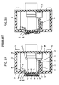
Fig. 33 is a cross section corresponding to Fig. 26, schematically
illustrating the embodiment in the fifth mode of carrying out the present
invention.
DESCRIPTION OF MODES OF CARRYING OUT THE INVENTION
FIRST MODE OF CARRYING OUT THE INVENTION
A first mode of carrying out the present invention is a depression
responsive two-step switch unit in which the marginal portion of the elastic
sheet is carried by a case.
The first mode of carrying out the present invention will be briefly
described with reference to Fig. 4. In the example shown, a second step
switch 36 is disposed on a rear plate 39h within a case 39 and a reinforcing
plate 35 is disposed on top of the second step switch 36. A plurality of first
step switches 34s are disposed on the reinforcing plate 35. A key operation
base 33 is disposed on the side of the reinforcing plate 35 which is located
toward the first step switch 34s. At locations corresponding to each of the
first step switches 34s, the key operation base 33 is formed with depression
openings 33a extending therethrough. A knob 32 is disposed on the front
side of the key operation base 33.
The knob 32 includes depressing pieces 32a which are formed on an
extremely pliable elastic sheet 32c which comprises a thermoplastic elastomer
or a silicone rubber at locations corresponding to one of the first step switches
34s, and each depressing piece 32a has a depressed surface 32a2 which is
located forwardly of the elastic sheet 32c. Each depressing piece 32a is at
least partly located within the depression opening 33a formed in the key
operation base 33 and includes a small projection 32b which projects from the
surface opposite from the depressed surface 32a2. Each small projection
32b is located close to or is in contact with a corresponding one of the first
step switches 34s. The marginal portion 32d of the elastic sheet 32c is
retained by the case 39. In the example shown, the case 39 comprises a rear
plate 39h, sidewalls 39a and 39d which are integral therewith, and a cover 31
which abuts against and which is secured to the end faces of the sidewalls 39a
and 39d to serve as a front plate. The marginal portion 32d of the elastic
sheet 32c is held sandwiched between the cover (front plate) 31 and the
sidewall 39a to be retained by the case 39.
The knob 32 and the key operation base 33 are secured together as
are the first step switches 34s and the reinforcing plate 35, whereby they are
simultaneously reciprocable with respect to the rear plate 39h. In the
example shown, the second step switch 36 is constructed to be automatically
reset when it is released from the depression or assumes a turn-off condition
while desirably providing a clicking sensation or a sensation that a switch
operation has been made.
First Embodiment
A first embodiment as a specific example of the first mode of
carrying out the present invention will now be described. It should be
understood that in the description to follow, corresponding parts which appear
throughout the drawings are designated by like reference numerals in order to
avoid a duplicated description as much as possible.
A cross section of the first embodiment taken along the line IV-IV
shown in Fig. 5 is shown in Fig. 4, a plan view is shown in Fig. 5, and the
exploded perspective view is shown in Fig. 6.
A cover (front plate) 31 comprises a metal sheet which is machined
as required, and includes a square portion 31a in which a circular opening 31b
is formed. Each side of the square portion 31a has a U-shaped detent 31c
having short limbs which is bent in a direction perpendicular to the square
portion 31a to extend toward the rear plate 39h.
A knob 32 comprises a square-shaped elastic sheet 32c, which
extends outside the opening 31b formed in the cover 31 except for its
marginal portion 32d to define a circular top surface on which five depressing
pieces 32a are formed as projections in this example. One of the depressing
pieces 32a which is located centrally has a circular configuration, while the
depressing pieces 32a which are located laterally on the opposite sides of the
central depressing piece 32a are triangular in configuration. The internal
surface of each depressing piece 32a projects beyond the elastic sheet 32c
toward the rear plate 39h as shown in Fig. 4, and a small projection 32b is
formed centrally on the end face of the projection. In this example, the
depressing piece 32a, the small projection 32b and the elastic sheet 32c are
integrally molded with a thermoplastic elastomer, and thus is constructed with
an extremely pliable material.
The key operation base 33 is molded from a hard resin such as ABS
resin or polycarbonate and is in the form of a disc which corresponds to the
circular top surface of the knob 32. The key operation base 33 is formed
with depression openings 33a which extend therethrough at locations
corresponding to each depressing piece 32a of the knob 32 and which are
larger than the depressing piece 32a. The centrally disposed depression
opening 33a is circular in the similar manner as the depressing piece 32a
which corresponds thereto while the remaining depression openings 33a are
triangular in configuration. While the key operation base 33 and the knob 32
are shown separately in Fig. 6, in the present example, they are integrally
molded, and the elastic sheet 32c is secured to the key operation base 33
without any slack therebetween.
In the present example, the first step switch 34s uses a membrane
sheet 34 which is constructed in the similar manner as the membrane sheet 6
of the prior art described above in connection with Figs. 1 to 3. While not
specifically shown in Figs. 4 to 7, the five membrane switches acting as first
step switches 34s are formed, each constructed in the similar manner as the
membrane switch 6s shown in Fig. 3A and having fixed contacts 6d and 6e
and the movable contact 6f. In Fig. 4, such first step switches (membrane
switches) 34s are indicated by blank areas (the same is true for a
corresponding membrane switch). A tail 34a which is used to take out the
lead wire for each of the fist step switches 34s is connected to part of the
peripheral edge of the membrane sheet 34.
A reinforcing plate 35 comprises a stainless steel sheet, for example,
and has substantially similar configuration as the membrane sheet 34.
The second step switch 36 shown in this example comprises a
switch body 36s which is constructed in the similar manner as the membrane
switch 36s shown in Fig. 3, for example, a click plate 37 and a pusher 38.
The membrane sheet 40 on which the membrane switch 36s acting as a switch
body is constructed is shown in Fig. 6 as being separate from the membrane
sheets 34, but they are integrally formed through a connector 40a as shown in
Fig. 4, and the connector 40a is folded to place the membrane sheets 34 and
40 on the opposite sides of the reinforcing plate 35. The membrane sheet
36s acting as the switch body is also shown as a blank area in Fig. 4 (the same
applies for a similar switch).
In the present example, an arrangement is made to provide a
clicking sensation from a switch operation of the second step switch 36 in a
manner mentioned previously, and the click plate 37 is disposed in the region
of the membrane switch (switch body) 36s of the membrane sheet 40 on the
opposite side of the reinforcing plate 35. The click plate 37 comprises a
dish-shaped springy metal sheet.
A pusher 38 is interposed between the click plate 37 and the rear
plate 39h so that a restoring force acts automatically when the second step
switch 36 is released from the depression. The pusher 38 may be formed of
rubber, for example, and has a square-shaped flat plate 38a which is centrally
formed with a dome 38b which projects toward the rear plate 39h. A
projection 38c is formed centrally on the internal surface of the dome 38b so
as to project toward the click plate 37.
The case 39 is formed of a hard resin such as ABS resin or
polycarbonate and is open toward the front, and is in the form of a shallow
square, with each comer being rounded. The sidewall 39a which forms one
side of the square is somewhat extended externally, and a notch 39b is formed
in its end face which is disposed toward the front side. This illustrates an
arrangement to allow the tail 34a to be guided externally. In order to fasten
the case 39 and the cover 31 together, a pair of small detent tabs 39c are
formed on the external surface of the sidewall 39a while the external surface
of the sidewalls 39d, which form the remaining three sides of the square, is
formed with a detent projection 39e of a substantial length which extends
along the respective side.
In order to allow the knob 32 to be positioned when mounting it on
the case 39, in the present example, a boss 39f is fixedly mounted on the rear
plate 39h at a location close to the internal surface of each rounded comer of
the case 39. The marginal portion 32d of the knob 32 and the top plate 31 a
of the cover 31 are formed with openings 32f and 31e, respectively, through
which the bosses 39f can be passed. A boss 39g is formed centrally on the
notch 39b of the case 39 on its front side, and an opening 34b is formed in an
end of the membrane sheet 34 which is located toward the tail 34a for passing
the boss 39g. It is to be noted that openings 31f, which are formed radially
outward of the four openings 31 e in the cover 31 are used for purpose of
mounting the two-step switch unit.
In order to position and secure the membrane sheet 34 of the key
operation base 33 and the reinforcing plate 35 relative to each other, a pair of
bosses are formed on the key operation base 33 on the side which faces the
rear plate 39h in this example, even though such bosses are hidden from sight
in Fig. 6, and the membrane sheet 34 and the reinforcing plate 35 are formed
with a pair of openings 34c and 35a, respectively, for passing these bosses.
In order to position and secure the membrane switch (switch body)
36s of the membrane sheet 40, the click plate 37 and the pusher 38 relative to
each other, in the present example, the flat plate 38a of the pusher 38 is
formed with a pair of bosses 38d, and openings which pass these bosses 38 d
are formed in the reinforcing plate 35, the membrane sheet 34 and the key
operation base 33. Numerals 34d and 33b shown in Fig. 6 shows such
openings. It should be noted that the openings formed in the reinforcing
plate 35 for passing the bosses 38d are hidden from sight.
The assembly of parts mentioned above will now be described.
Initially, the assembly of the knob will be sequentially described.
Subsequently, the knob assembly is assembled into the case 39.
This assembling operation takes place by passing the bosses 39f on the case
39 through the four openings 32f formed in the marginal portion 32d of the
knob 32 and passing the boss 39g on the case 39 through the opening 34b
formed in the membrane sheet 34. In this manner, the knob assembly is
positioned and received within the case 39. Fig. 7 shows this condition.
Finally, the cover 31 is attached to complete the two-step switch
unit. The cover 31 is attached by engaging four detents 31c with the detent
projections 39c and 39e of the case 39.
Fig. 8 shows, to an enlarged scale, one location where the marginal
portion 32d of the knob 32 and the square portion 31a of the cover 31 are
positioned by the bosses 39f on the case 39. The cover 31 is positioned by
passing the opening 31e thereof over the boss 39f, and the periphery of the
knob 32 or the marginal portion 32d of the elastic sheet 32c is held
sandwiched between the case 39 and the surface plate or the cover 31 to be
retained by the case 39.
In the example shown in Fig. 8, a ring-shaped rib 32g is formed
around the opening 32f in the periphery of the knob 32 (or the marginal
portion of the elastic sheet) 32d on the side which faces the cover 31, and the
square portion 31a of the cover 31 abuts against the marginal portion 32d of
the knob 32 only at this ring-shaped rib 32g while a small clearance is
maintained with respect to the marginal portion 32d in the remainder.
The two-step switch unit which is assembled in the manner
mentioned above has a construction as shown in Fig. 4 where the pusher 38 is
located centrally on the internal surface of the rear plate 39h of the case 39,
and the click plate 37, the reinforcing plate 35 which carries membrane sheets
34 and 36 on the opposite sides and the key operation base 33 which is
integral with the knob 32 are sequentially mounted thereon.
The knob 32 or the elastic sheet 32c thereof is disposed on the front
side of the key operation base 33 and its marginal portion 32d is supported by
the case 39, substantially blocking the opening in the case 39 by the knob 32.
In this example, it is secured to the case 39 at a plurality of locations (which
are four locations as shown), and other non-anchored portions remain to be
free ends.
The operation of the two-step switch unit according to the first
embodiment will now be described. When any desired one of the depressing
pieces 32a of the knob 32, for example, a central depressing piece is gently
depressed, the elastic sheet 32c located around this depressing piece 32a,
namely, the portion of the elastic sheet 32c which is located between the
peripheral edge of the depression opening 33a and the depressing piece 32a
becomes flexed as shown in Fig. 9A, thus depressing the small projection 32b.
The membrane switch 34s which serves as the first step switch is depressed
by the small projection 32b, whereby the contacts (not shown) which are
located opposite thereto contact each other to turn the first step switch 34s on.
When the depressing piece 32a is further depressed, the marginal
portion 32d of the knob 32 becomes flexed as shown in Fig. 9B, and the key
operation base 33 which is integral with the knob 32, the reinforcing plate 35
which holds the membrane sheets 34 and 40 and the click plate 37 are
depressed in an integral manner, thus depressing the pusher 38.
The dome 38b of the depressed pusher 38 is squeezed to deform in
a manner shown in Fig. 9B, whereby the projection 38c of the pusher 38
presses against the click plate 37. The click plate 37 which is pressed in this
manner has its central portion reversed in position relative to the peripheral
surface of the click plate 37 (hereafter such phenomenon will be simply
referred to as a reversal) with a click sensation, thus pressing against the
membrane switch 36s which serves as the switch body of the second step
switch. When the click plate 37 presses against the membrane switch 36s,
the contacts (not shown) which are located opposite thereto contact each other
to turn the second step switch 36 on.
When this pressing action is gradually released, the resilient
restoring force of the pusher 38, the click plate 37 and the marginal portion
32d of the knob 32 causes the parts which have been depressed in an integral
manner to return to their original positions to turn the second switch 36 off.
When the depression is completely released, the depressing piece 32a and the
small projection 32b return to their original positions relative to the key
operation base 33 under the influence of the restoring force of the membrane
sheet 34 to turn the first step switch 34s off.
In the present example, the membrane switch 34s which serves as
the first step switch is disposed within the switch unit, and accordingly,
contacts can be formed on a very thin film, for example, a polyethylene film
by a printed circuit technology, allowing the reaction thereof to be minimized.
In addition, since the first step switch is turned on by a flexure of only the
elastic sheet 32c which comprises a pliable thermoplastic elastomer, the
on-load of the first step switch can be minimized. More specifically, in the
two-step switch unit of this embodiment, the key operation surface is
constructed by the key operation base 33 which retains the knob 32, and
accordingly, the first step switch can be turned on with a contact of the finger
with the depressing piece which is on the order of tangibly feeling the key
operation surface with the finger. In addition, the profile of the knob 32 is
maintained by the key operation base 33 without any likelihood of being
damaged upon contact with an external member while maintaining the key
operation surface.
In addition, the switch bodies of the first and the second step switch
are both formed by the membrane sheets 34 and 40, respectively, in the
present example, allowing a thin and compact construction while reducing the
number of steps of assembly to permit the switch unit to be constructed
inexpensively.
Furthermore, in the example shown, the peripheral portion of the
elastic sheet 32c or the marginal portion 32d of the knob 32 is not secured to
the case 39 along the full perimeter thereof, but is secured by being positioned
at a plurality of points which are four points representing the bosses 39f of the
case 39 in this example, whereby a construction is achieved which allows an
elastic deformation of the marginal portion 32d to occur readily in the
direction of depression while making an elastic deformation in a direction
perpendicular to the direction of depression or in a direction parallel to the
rear plate 39h hardly occurring. In other words, the knob 32, the key
operation base 33 and the reinforcing plate 35 are readily displaceable in the
direction of a normal depression, but are hardly displaceable in a direction
perpendicular to the direction of a normal depression. Thus, when the knob
32 is depressed, an adequate degree of tension occurs in the marginal portion
32d as a result of securing at a plurality of points which are four points in the
present example, and if another depressing piece 32a is depressed, or if the
knob 32 is edgewise depressed, a rotation of the key operation base 33 about
the point of contact between the pusher 38 and the rear plate 39h is unlikely to
occur. In addition, if the knob 32 were depressed obliquely with respect to
the direction of a normal depression, the second step switch can be depressed
under a condition that the key operation base 33 assumes a small inclination,
affording a good touch and an evenly stroking sensation at this point. In
addition, because the key operation surface is defined by the knob 32 of an
elastic material which comprises a thermoplastic elastomer, additional effects
are obtained that it is comfortable to touch and there is a high grade
leather-like appearance.
Second Embodiment
In the second embodiment, in order to reduce the number of parts, a
sidewall 39a is molded integrally with a knob 32 as shown in Fig. 10, and the
marginal portion 32d of the elastic sheet 32c (knob 32) is secured to the end
face of the sidewall 39a along the full perimeter as by an integral molding.
A redundant portion 32h which is U-shaped in section is formed in the
marginal portion 32d of the elastic sheet 32c (knob 32) to extend along the
inner periphery of the sidewall 39a. This facilitates an elastic deformation of
the marginal portion 32d in a direction toward the rear plate and also makes
an elastic deformation in a direction parallel to the rear plate more difficult to
occur. In other words, the knob 32, the key operation base 33 and the
reinforcing plate 35 are readily displaceable in the direction of a normal
depression and are hardly displaceable in a direction perpendicular to the
direction of a normal depression. Accordingly, if the knob 32 is edgewise
depressed, there occurs no inclination of the knob 32 (the key operating base
33 and the reinforcing plate 35), allowing the second step switch to be
operated with a good touch and an evenly stroking sensation. It is to be
noted that in the present example, the rear plate 39h of the case 39 is formed
by a metal sheet in order to reduce the thickness. Securing the marginal
portion 32d of the elastic sheet 32 to the case 39 over the full perimeter may
take place in the example shown in Figs. 4 to 8 by omitting the ring-shaped
rib 32g shown in Fig. 8 and holding the marginal portion 32d sandwiched
between the case 39 and the cover 31 over the full perimeter.
The example shown in Fig. 10 illustrates that the depressing piece
32a and the small projection 32b of the knob 32 are integrally constructed
with a resin material. Specifically, the elastic sheet 32c is formed with a
passing opening 32i in a manner corresponding to each depressing piece 32a,
and each depressing piece 32a is formed by a hard resin such as ABS resin or
polycarbonate, with a flange 32a1 integrally formed with the depressing piece
32a toward a depressed surface 32a2 and each depressing piece 32a is passed
through the corresponding passing opening 32i and the flange 32a1 is brought
into abutment against the elastic sheet 32c around the edge of the passing
opening 32i. In the present example, a surface opposite from the surface
against which the flange 32a1 around the edge of the passing opening 32i
abuts is integrally molded with a ring-shaped rib 32c1. The elastic sheet
32c which comprises a thermoplastic elastomer, and the depressing piece
32a and the small projection 32b which comprise a hard resin are integrally
molded to be secured together. By choosing a resin material for the
depressing piece 32a, a desired feeling as the depressing piece 32a is touched
when it is to be depressed can be obtained.
In the example shown in Fig. 10, the pusher 38 shown in Fig. 4 is
omitted, and a projection 39i is integrally formed at the center of the internal
surface of the rear plate 39h, with the projecting end face of the projection
abutting against the central portion of the convex side of the click plate 37.
It will be seen that in this instance also, as one of the depressing pieces 32a is
depressed, the click plate 37 is pressed by the projection 39i to reverse,
whereby the switch body 36s of the second step switch is turned on.
SECOND MODE OF CARRYING OUT THE INVENTION
The second mode of carrying out the present invention is distinct
from the first mode of carrying out the invention in that a key operation base
33 is disposed on the front side of an elastic sheet 32c and that the elastic
sheet 32c is retained not by the case, but by the key operation base 33 and a
reinforcing plate 35, as indicated in Fig. 11, for example, which illustrates a
cross section corresponding to Fig. 4. Specifically, the key operation base
33 is formed with a depression opening 33c in a manner corresponding to
each depressing piece 32a, and the depressing piece 32a faces the front side
from within the case 39 through the respective depression opening 33c. In
Fig. 11, a depressed surface 32a2 which is configured to be similar to a part of
a spherical surface projects externally from the surface of the key operation
base 33. There is a close clearance between the peripheral surface of the
depressing piece 32a and the depression opening 33c, and the key operation
surface is formed by the surface of the key operation base 33 and the
depressed surface 32a2 which substantially blocks the depression opening 33c.
An operator of the two-step switch unit touches the key operation surface with
a finger of his hand to operate it for depression. It is not the key operation
base 33, but the elastic sheet 32c that contacts the reinforcing plate 35 or the
membrane sheet 34. The marginal portion 32d of the elastic sheet 32c is
held sandwiched between the key operation base 33 and the reinforcing plate
35 to maintain the elastic sheet 32c in a slack-free condition. In other
respects, the second mode of carrying out the invention may be fundamentally
same as in the first mode of carrying out the invention. A specific example
of the second mode of carrying out the invention will now be described as a
third embodiment.
Third Embodiment
The third embodiment is shown in Figs. 11 to 16. In the third
embodiment, instead of the cover 31 shown in the first embodiment, a case 39
is formed with a surface plate 39j in an integral manner with its sidewall, and
a large circular opening 39k is formed in the surface plate 39j. A key
operation base 33 is disposed to substantially block the opening 39k, and the
key operation base 33 is formed with a depression opening 33c in a manner
corresponding to each depressing piece 32a. In the present example, there
are nine depression openings 33c as shown in Fig. 12, one being disposed at
the center while the remaining eight openings are disposed on a common
circle at an equal interval.
As mentioned previously, in the present example, the depressing
piece 32a and the small projection 32b are integrally molded with a hard resin,
and this is adhesively secured to or integrally molded with the elastic sheet
32c which comprises a thermoplastic elastomer 32. Each depressing piece
32a is disposed in the depression opening 33c in the key operation base 33 to
face the exterior. Only a depressed surface 32a2, which forms a part of
spherical surface, is slightly exposed from the surface of the key operation
base 33 to permit a finger to contact and to slip along the key operation
surface so that the existence of the depression piece 32a can be confirmed by
tactile impression. The elastic sheet 32c is located on the reinforcing plate
35 through the membrane sheet 34 interposed in this instance, and has the
small projection 32b as the only portion where it contacts a first step switch,
which is a membrane switch 34s within a membrane sheet 34 in this example.
For this reason, an air gap formation 32j is formed as a projection
on the side of the elastic sheet 32c which is disposed toward the reinforcing
plate 35 in a manner corresponding to each adjacent small projection 32b or
to the center position between adjacent membrane switches 34s, thus
producing an air gap 41 between the elastic sheet 32c and the first step switch
(membrane switch) 34s. As shown in Figs. 11, 14 and 16, the air gap
formation 32j is located at a midpoint between adjacent depressing pieces 32a
as viewed in the direction in which the depressing pieces 32a are arrayed.
The marginal portion 32d of the elastic sheet 32c has an increased thickness
and defines a ring-shaped air gap formation which is centered about the
centrally located depressing piece 32a.
As a result of abutment of these air gap formations 32j against the
membrane sheet 34, the small projection 32b moves close to or contacts the
membrane switch 34s. In this example, the reinforcing plate 35 comprises a
molding of a hard resin such as ABS resin or polycarbonate. As shown in
Figs. 13 and 14, the key operation base 33 is integrally formed with a plurality
of bosses 33d as projections on the rear side thereof, and these bosses 33d are
sequentially passed through openings 32k formed in the elastic sheet 32c,
openings 34c formed in the membrane switches 34s and openings 35a formed
in the reinforcing plate 35 in a manner shown in Fig. 15, and their projecting
ends are caulked by heat. In other words, heat and pressure are applied to
increase the cross section of the bosses, and these portions are engaged with
portions of the openings 35a which have a greater diameter. In this manner,
the key operation base 33, the knob 32, the membrane switches 34s and the
reinforcing plate 35 are positioned relative to each other and are also secured
together.
As shown in Fig. 11, a spacing between the air gap formation on the
marginal portion 32d of the elastic sheet 32c and the closest small projection
32b is substantially equal to a spacing between that smaller projection 32b
and the air gap formation 32j which is located on the other side from the
marginal portion 32d and which is closest thereto. Unificaton of the key
operation base 33, the membrane switches 34s and the reinforcing plate 35 by
caulking of bosses under heat which take place in the first embodiment
mentioned above takes place in the similar manner as unification of the key
operation base 33, the knob 32, the membrane switch 34s and the reinforcing
plate 35 by caulking of bosses under heat in the third embodiment.
In the present example, a tact switch is used for the second step
switch 36. The tact switch 36 includes an internal resilient member which is
reversed in configuration when an actuator 36a is depressed into a switch case
36b by an external force to assume a switch-on condition. The reversal of
the resilient member provides a tactile impression (clicking sensation) of a
switch operation. When the actuator 36a is released from the external force,
the resilient restoring force restores the configuration of the resilient member,
thus resuming a switch-off position. The tact switch 36 is disclosed, for
example, in Japanese Utility Model Registration No. 2,557,784 (issued
December 17, 1997).
The tact switch 36 is secured centrally on the internal surface of the
case rear plate 39h, for example, at a predetermined position which is
previously marked when the rear plate 39h is formed. As shown in Figs. 11,
15 and 16, the projecting end face of the actuator 36a of the tact switch 36 is
abutted by the reinforcing plate 35, which is an integrally formed projection
35b in the present example. The resilient restoring force of the resilient
member contained in the tact switch 36 acts through the actuator 36a to push
back the reinforcing plate 35 toward the surface plate 39j of the case 39 until
a flange 33e disposed around the outer periphery of the key operation base 33
abuts against the internal surface of the surface plate 39j. The peripheral
edge of the disk-shaped key operation base 33 is folded toward the rear side to
extend through a small distance, and the flange 33e is integrally formed
around the outer periphery of such extension 33f.
In the present example, the case 39 is integrally molded with the
sidewall of the surface plate 39j, as mentioned previously, allowing the rear
plate 39h to be detachable. As shown in Figs 11, 13 and 14, a notch 39m is
formed in one side of the rear plate 39h, allowing the membrane sheet tail 34a
to be led out. After the key operation base 33, the knob 32, the membrane
switches 34s and the reinforcing plate 35 are unified in a manner mentioned
previously, these are inserted into the case 39 from the rear side, the rear plate
39h is brought into abutment against the end face of the sidewall of the case
39 as illustrated in Fig. 11, screws 42 are inserted into openings 39n formed in
the rear plate 39h as shown in Figs. 13, 14 and 16, and when the screws 42 are
clamped into bores 39p which are formed in the case sidewall, the rear plate
39h is unified with the case.
A printed circuit board is used for the rear plate 39h. A position
marker (not shown) which is applied when forming the printed circuit may be
utilized when mounting the tact switch 36 with a face bond. As shown in
Fig. 11, the tail 34a of the membrane sheet is taken out through the notch 39m
and is connected to a connector 43 which is mounted on the outer surface of
the rear plate 39h. While the connector 43 has not been shown in the first
and the second embodiment, it is a general practice that the tail 34a of the
membrane sheet is connected to a connector which is mounted on the outer
surface of the case 39, as illustrated in Fig. 11.
In the third embodiment, when one of the depressing pieces 32a is
depressed into the case 39, a portion of the elastic sheet 32c which lies
between that depressing piece 32a and the air gap formation 32j which is
close thereto undergoes an elastic deformation (becomes flexed) initially, as
shown in Fig. 17A, and a corresponding one of the first step membrane
switches 34s is depressed to be turned on. The on-load which occurs at this
time can be reduced to a very low level in the similar manner as in the first
mode of carrying out the invention, because such load accrues from only the
reactions of the elastic sheet 32c which has an extremely high pliability and
the membrane switch 34s.
When the depressing piece 32a continues to be depressed into the
case 39, the reinforcing plate 35 moves toward the rear plate 39h against the
reaction from the actuator 36a of the tact switch 36, as shown in Fig. 17B,
whereby the actuator 36a is driven into the switch case 36b to turn the second
step switch 36 on with a clicking sensation. When the depressing piece 32a
is released from the depression, the resilient restoring force of the resilient
member within the tact switch 36 causes the reinforcing plate 35 to move
toward the surface plate 39j, turning the second step switch 36 off, and the
membrane switch 34s or the first step switch which has been turned on is
turned off again by the restoring force of the elastic sheet 32c.
In the second mode of carrying out the invention, the marginal
portion 32d of the elastic sheet may be carried by the reinforcing plate 35 as
by being adhesively bonded thereto, for example.
THIRD MODE OF CARRYING OUT THE INVENTION
In the third mode of carrying out the invention, the elastic sheet
itself represents the surface of the case or the key operation surface, and the
marginal portion of the elastic sheet is retained by the case and the key
operation base. As illustrated by a section corresponding to Fig. 4 in Fig. 18,
for example, a knob 32 faces the exterior through an opening 39k in a surface
plate 39j, a key operation base 33 is disposed on the rear side of the knob, and
a marginal portion 32d of the elastic sheet 32c is retained by a marginal
portion of the key operation base 33. Disposed on the rear side of the key
operation base 33 is a reinforcing plate 35 on which a first step switch 34s is
disposed, and a second step switch means 36 is interposed between the
reinforcing plate 35 and a rear plate 39h. In other words, as compared with
Fig. 11, the knob 32 and the key operation base 33 are interchanged in
position. A specific example of the third mode of carrying out the invention
will now be described in terms of a fourth embodiment.
Fourth Embodiment
A fourth embodiment is shown in Fig. 18. In the fourth
embodiment, a key operation base 33 which is configured in substantially the
same manner as the key operation base 33 used in the third embodiment is
employed, and a knob 32 is disposed in abutment against the front surface of
the key operation base 33. The knob 32 which is shown in this example has
a depressing piece 32a and a small projection 32b which are integrally molded
from a hard resin in the similar manner as the knob shown in Fig. 10. Each
depressing piece 32a is passed through a passing opening 32i formed in an
elastic sheet 32c which comprises a thermoplastic elastomer, and a flange
32a1 which is formed around the periphery of the surface of the depressing
piece 32a is adhesively bonded to the elastic sheet 32c. A depressed surface
32a2 inclusive of the flange 32a1 is in the form of part of a spherical surface.
Each depressing piece 32a is passed through a depression opening
33c in the key operation base 33, and the elastic sheet 32c, while being in
abutment against the front side of the key operation base 33 without any slack,
extends along the outer peripheral surface of an extension 33f of the key
operation base 33, and further extends along the front side of the flange 33e in
its marginal portion 32f, which is in turn retained by the marginal portion of
the key operation base 33 or the flange 33e in the present example. By way
of example, the knob 32 may be integrally molded with respect to the molded
key operation base 33. Alternatively, the marginal portion 32f may be
adhesively secured to the flange 33e.
Each depressing piece 32a is passed through the depression opening
33c in the key operation base 33. The depression opening 33c is a
concentric circle centered about the depressing piece 32a, and a spacing
between an inner peripheral surface of the depression opening 33c and the
peripheral surface of the depressing piece 32a is chosen to be a certain size so
that a region of the elastic sheet 32c which is disposed therebetween can
readily be flexed if the depression applied to the depressing piece 32a is very
weak, and assumes substantially same value for the spacing. Each small
projection 32b for each depressing piece 32a is in contact with or lies close to
the first step switch, which is the membrane switch 34s in the present example,
in the same manner as in the described embodiments. In other words, the
fourth embodiment is distinct from the second embodiment principally in the
manner of retaining the elastic sheet 32c. It should be understood that the
unification of the key operation base 33 and the reinforcing plate 35 takes
place in the similar manner as in the third embodiment.
In the present example, the membrane switch 36s is used for the
second step switch means 36, and this is mounted on the internal surface of
the rear plate 39h. Specifically, the membrane switch 34s which serves as
the first step switch is extended to form the membrane sheet 40 inclusive of
the second step switch 36s, in the similar manner as in the first embodiment,
but in the fourth embodiment, the connector 40a is not directly folded on the
rear side of the reinforcing plate 35, but is folded on the internal surface of the
rear plate 30h and is extended along the internal surface. The membrane
switch 36s disposed within the extended membrane sheet 40 is positioned so
as to be opposite to the center of the reinforcing plate 35. A click plate 37 is
interposed between this portion for the membrane switch 36s and a projection
35b on the reinforcing plate 35. The click plate 37 is in contact with the
projecting end face of the projection 35b at the center of the convex side
thereof.
It will be readily seen that in the fourth embodiment, as the
depressing piece 32a is depressed, the membrane switch 34s which serves as a
corresponding first step switch can be turned on with a very weak force as in
the second embodiment. When the depression is continued after the first step
switch 34s has been turned on, the knob 32, the key operation base 33 and the
reinforcing plate 35 move toward the rear plate 39h in an integral manner,
whereby the projection 35b causes an elastic deformation of the click plate 37,
the reversal of which turns the membrane switch 36s which serves as the
second step switch on.
If the depressing piece 32a is now released from depression, the
resilient restoring force of the click plate 37 urges the reinforcing plate 35
toward the surface plate 39j, thus turning the membrane switch 36s off and
also turning the membrane switch 34s off.
It is desirable in the third embodiment that a clearance between the
peripheral surface of the depressing piece 32a and the inner peripheral surface
of the depression opening 33c be chosen to be narrow in order to prevent the
ingress of dust, and in consideration of the maneuverability when moving the
finger to select a depressing piece and a good appearance. However, in
order for the first step switch 34s to be able to respond to a weak depression
to be turned on, it is necessary that the depressing piece 32a is displaced
without interference with the depression opening 33c if the depressing piece
is depressed with a very weak force. In this respect, a reduction in the
clearance between the peripheral surface of the depressing piece 32a and the
inner peripheral surface of the depressing opening 33c is limited in view of
the dimensional accuracy and the cost required.
However, in the fourth embodiment, the spacing between the
peripheral surface of the depressing piece 32a and the inner peripheral surface
of the depression opening 33c becomes relatively large because of the
necessity to make the on-load of the first step switch 34s as small as possible,
and accordingly, it is possible to turn the first step switch 34s on reliably in
response to a weak depression force without causing a problem of
interference or contacting each other therebetween. In addition, the key
operation surface is covered by the knobs 32 without leaving any clearance,
thus precluding the likelihood of the ingress of dust and providing a good
touch when selecting the depressing piece 32a by tangibly feeling it with a
finger and also providing a good appearance.
In the third mode of carrying out the invention, rather than
extending the marginal portion 32d of the elastic sheet 32c to the internal
surface of the case surface plate 39j, it may be molded on or adhesively
secured to the extension 33f of the key operation base 33.
MODIFICATIONS
KNOB
In the first embodiment, the depressing piece 32a and the small
projection 32b of the knob 32 may be formed with a hard resin in the similar
manner as the knob 32 shown in Fig. 10, while the remainder may be formed
of a thermoplastic elastomer. Alternatively, as shown in Fig. 19A, a portion
32a3 of the depressing piece 32a which projects from the surface of the elastic
sheet 32c may be formed with a hard resin while a remainder thereof 32a4
and the small projection 32b may be formed of a thermoplastic elastomer in
an integral manner with the elastic sheet 32c.
Also in the second embodiment, the knob 32 may be entirely
formed of a thermoplastic elastomer in the similar manner as the knob 32
shown in Fig. 4, or may be constructed in the manner shown in Fig. 19A.
In the third embodiment, the depressing piece 32a, the small
projection 32b, the elastic sheet 32c and the air gap formation 32j of the knob
32 may be entirely formed by an integral molding from a thermoplastic
elastomer, as shown in Fig. 19B. Alternatively, the small projection 32b, the
elastic sheet 32c and the air gap formation 32j may be formed by an integral
molding from a thermoplastic elastomer while the depressing piece 32a may
be molded from a hard resin and unified with the former by adhesion or by a
molding operation, as shown in Fig. 19C.
In the fourth embodiment, parts of the knob 32 may be entirely
formed of a thermoplastic elastomer as shown in Fig. 19D. Alternatively,
the elastic sheet 32c and the portion 32a3 which is exposed externally may be
formed of a thermoplastic elastomer while the remainder 32a4 of the
depressing piece 32a and the small projection 32b may be integrally formed
with a hard resin, as shown in Fig. 19E.
In each of the first to the fourth embodiment, the thermoplastic
elastomer used in the knob 32 may be replaced by silicone rubber. It is also
possible to form only the small projection 32b with a separate resin material.
FIRST STEP SWITCH
In each of the first to the fourth embodiment, the membrane switch
which serves as the first step switch 34s need not be limited to the three
contact construction including a pair of fixed contacts and one movable
contact as shown in Fig. 3A, but may be constructed by one fixed contact 6d
and one movable contact 6f disposed opposite to each other as shown in
section in Fig. 20A, for example. In the arrangement shown in Fig. 3A, lead
wires for externally connecting the contacts 6a and 6b may be formed on the
flexible film 6a on which the fixed contacts are disposed, but in the
construction shown in Fig. 20A, it is necessary to form lead wires for external
connection of both the fixed contact 6b and the movable contact 6f on the
flexible films 6a and 6b, respectively.
An alternative construction as shown in Fig. 20B may be used.
Specifically, a reinforcing plate 35 is formed by a printed circuit board and the
fixed contacts 6d and 6e and their lead wires (not shown) may be printed on
the front surface while a flexible film 46 such as a polyethylene film or the
like is applied on top of the reinforcing plate 35 with spacers 45a and 45b
interposed, and a movable contact 6f is printed on the flexible film 46 so as to
be located opposite to the fixed contacts 6d and 6e. This flexible film 46 is
depressed by the small projection 32b (not shown in Fig. 20B) of the
corresponding knob 32 to become flexed, driving the movable contact 6f into
contact with the fixed contacts 6d and 6e and to achieve a switch-on condition.
When the depression is released, the movable contact 6f returns to its original
position to resume a switch-off condition. It is to be noted that in this
instance, a single fixed contact may be provided as shown in Fig. 20A and the
lead wire may be printed on the flexible film 46.
As shown in Fig. 20C, a small projection 32b which comprises a
conductive rubber or a metal material may be applied as an insert molding to
the center of the surface of the depressing piece 32a which is opposite from a
depressed surface 32a2, and the small projection 32b may have a planar
projecting end face which serves as a movable contact while a pair of fixed
contacts 6e and 6d and their associated lead wires may be printed on the
reinforcing plate 35 as shown in Fig. 20B so that the fixed contacts 6d and 6e
are located opposite to the small projection 32b acting as a movable contact,
thus defining a first step switch 34s.
Alternatively, to serve as a small projection 32b which also serves
as a movable contact, the small projection 32b may be constructed to have a
flat projecting end face, to which a conductive painting or a conductive paste
may be applied and hardened to form a movable contact 32b1 which
comprises a conductive layer, as shown in Fig. 20D.
While the first step switch 34s is shown alone in Figs. 20C and 20D,
it should be understood that such first step switch 34s is provided for each
depressing piece 32a. While an application to the third embodiment has
been illustrated, it may also be applied as each first step switch 34s in the first,
the second and the fourth embodiment.
In addition, each first step switch 34s in the first to the fourth
embodiment may comprise a switch similar to a so-called touch panel which
can be used as coordinate entry means, information entry means or menu
selection means or the like. By way of example, as indicated by an exploded
perspective view of Fig. 21A, flexible films 47a and 47b as may be formed by
polyethylene films are closely spaced by a spacer 48 and fixed relative to each
other, and a plurality of strip- like electrodes 49a and 49b are formed so as to
be parallel to each other on the opposing internal surfaces of the flexible films
47a and 47b. As viewed in a direction perpendicular to the flexible film 47a,
the electrodes 49a and 49b are orthogonal to each other. While not shown, a
small projection 32b of each depressing piece 32a is disposed in contact with
the flexible film 47a at each point of intersection.
Thus if some depressing piece 32a is depressed, electrodes 49a and
49b at a corresponding point of intersection contact each other to achieve a
switch-on condition, and when the depression is released, the electrodes 49a
and 49b which have been in contact with each other move away from each
other to resume a switch-off condition. It is only necessary that the
electrodes 49a and 49b intersect with each other as viewed in a direction
perpendicular to the flexible film 47a or the key operation surface, and the
plurality of electrodes 49a and 49b need not be parallel to each other, nor it is
required that they are straight lines. Since this is not a touch panel which is
commonly used, the use of a transparent film or transparent electrode is not
required, and because they are not exposed externally, the thickness of each
flexible film 47a, 47b can be reduced as desired. It is pointed out that a
touch panel of the kind described is disclosed in Japanese Laid-Open Patent
Application No. 61,603/93 (issued March 12, 1993).
A touch panel which uses resistive films is also known and can be
used as the first step switch 34s. By way of example, as illustrated in Fig.
21B in the form of an exploded perspective view, flexible films 47a and 47b
are closely spaced by a spacer 48 and disposed opposite to each other.
Resistive films 51a and 51b are formed on the opposing surfaces of the
flexible films 47a and 47b. Electrodes 52a and 52b are formed at one end of
one of the resistive films, 51b, while electrodes 52c and 52d are formed at
remaining ends. While not shown, small projections 32b of a plurality of
depressing pieces 32a are disposed on the closely spaced resistive films 51a
and 51b in contact with the flexible film 47a. The resistive films 51a may
comprise a conductive film having a small resistance.
When one of the depressing pieces 32a is depressed, a
corresponding location of the resistive film 51a comes into contact with the
resistive film 51b. A voltage which is developed across the resistive film
51a when a voltage is applied across the electrode 52a and 52b under this
condition and a voltage which is developed across the resistive film 51a when
a voltage is applied across the electrodes 52c and 52d are measured, and on
the basis of these voltage values, a detection is made of which one of the
depressing pieces 32a has been depressed or whether the first step switch 34s
which corresponds to that depressing piece 32a has been operated and turned
on. A touch panel of the kind described is disclosed in Japanese Laid-Open
Patent Application No. 189,150/93 (issued July 30, 1993), for example.
SECOND STEP SWITCH
Each of the second step switches 36 shown in the first to the fourth
embodiment may be constructed as shown in Fig. 22A. A pair of fixed
contacts 53a and 53b and their external connection lead wires (not shown) are
formed by printed circuit technology on the surface of the reinforcing plate 35
which is located opposite to the rear plate 39h. A click plate 37 is mounted
on the reinforcing plate 35 in a manner to oppose the fixed contacts 53a and
53b with a ring-shaped spacer 54 interposed therebetween. The click plate
37 is convex toward the rear plate 39h, and a projection 39i is integrally
formed on the rear plate 39h in contact with the center of the click plate 37.
When the reinforcing plate 35 moves toward the rear plate 39h in response to
the depression of the depressing piece 32a, the click plate 37 undergoes an
elastic deformation to reverse, whereupon the click plate 37 moves into
contact with the both fixed contacts 53a and 53b to achieve an electrical
conduction therebetween, thus turning the second step switch 36s on. When
the depression is removed, the elastic deformation of the click plate 37 is
removed to resume a switch-off condition.
The second step switch 36 may also be constructed as shown in Fig.
22B. This represents what is referred to as a rubber contact switch which
provides a clicking sensation. This switch is dome-shaped and includes a
top 55a, the top surface of which is disposed in abutment against the rear
surface of the reinforcing plate 35 at a central position while the end of the
top 55a which is located opposite from the top surface is connected around its
periphery with a ring-shaped base 55c through a skirt 55b. A projection 55d
is formed on the inner surface of the top 55a, and a movable contact 53c is
formed on the projecting end face of the projection 55d. The base 55c is
disposed in abutment against the central portion of the rear plate 39h, and
fixed contacts 53a and 53b are formed on the rear plate 39h inside the base
55c so as to be opposite to the movable contact 53c. The top 55a, the skirt
55b, the base 55c and the projection 55d are formed as an integral molding of
rubber material. The fixed contacts 53a and 53b and their external
connection lead wires (not shown) are printed on the rear plate 39h. The top
surface of the top 55a is secured to the reinforcing plate 35 or the base 55c is
secured to the rear plate 39h as by adhesion.
As the reinforcing plate 35 moves toward the rear plate 39h in
response to the depression of the depressing piece 32a, the skirt 55b
undergoes an elastic deformation to reverse, whereby the movable contact 53c
move into contact with the fixed contacts 53a and 53b, thus turning the switch
on. The reversal of the skirt 55b provides a clicking sensation. When the
depression is released, original configurations are restored due to the resilient
restoring force of the skirt 55b, thus resuming a switch-off condition.
It should be noted that each second step switch 36 shown in the first
to the fourth embodiment may also be used in other embodiments. For
example, the second step switch 36 shown in the first embodiment may be
used as the second step switch 36 in one of the second to the fourth
embodiment.
The second step switch 36 which has self-restoring force and which
provides a clicking sensation has been illustrated. However, while the
presence of the clicking sensation is desired in the prior art in due of a reliable
operation during a normal key entry, it is not essential. Where a second step
switch 36 which does not provide a clicking sensation is used, it is desirable
that a switch be used which requires a certain stroke before a switch-on
condition is reached or a switch which provides a stroking sensation. On the
other hand, if the second step switch 36 which provides the clicking sensation
is used, a switch with a reduced length of stroking can be used, allowing a
thin switch unit to be constructed.
With reference to the second step switch 36 used in the first to the
fourth embodiment, if a slight inclination of the knob 32, the key operation
base 33 and the reinforcing plate 35 in response to the depression can be
allowed, or if an arrangement is made which allows a rotation about a point of
contact between the surface plate 39j and the flange 33e in Fig. 11 such that a
point located on the other end is allowed to move toward the rear plate 39h,
the pusher 35b may be omitted if the actuator 36a can be directly driven by
the reinforcing plate 35 to turn the switch on without any influence of such
inclination upon a comer or shoulder of the switch case 36b which is disposed
on the opposite side from the rear plate 39h. Similarly, other corresponding
pushers can be omitted.
FOURTH MODE OF CARRYING OUT THE INVENTION
Another mode of carrying out the invention according to a second
aspect thereof is directed toward overcoming the problems of a conventional
depression responsive switch unit which have been described with reference
to Figs. 23 to 25. This will be described as the fourth mode of carrying out
the invention with reference to Fig. 26. A case 71 is constructed as a rigid
body, or constructed as a molding of a hard resin such as ABS resin,
polycarbonate or the like, for example, and a knob 72 which is formed of a
similar hard resin is disposed so as to block an opening 71b formed in the
surface plate 71a of the case 71. The knob 72 is retained by the case 71 by
using a thin-walled resilient member 76 such that it is readily deformable in
the direction of a normal depression, but is hardly deformable in a direction
perpendicular to the direction of a normal depression, or readily displaceable
in a direction perpendicular to the rear plate 71, but is hardly displaceable in a
direction parallel to the rear plate 71e.
The resilient member 76 is formed of a thin-walled metal, fiber,
paper, hard resin, elastomer, silicone rubber or the like which is hard to stretch,
but is pliable to bend. The resilient member 76 is configured to be
symmetrical with respect to the axis of the knob 72. A switch 73 having a
self-restoring function is mounted centrally on the internal surface of the rear
plate 71. When the knob 72 is depressed, the knob 72 drives the switch 73,
turning it on. At this time, if the depression is applied to one point around
the edge of the knob 72, the retaining function of the resilient member 76
causes the knob 72 to move in a direction perpendicular to the rear plate 71e.
Accordingly, the switch 73 is always turned on with an even depressing force,
allowing a long useful life of a return spring and providing a substantially
constant tactile impression and stroking length.
Fifth Embodiment
Figs. 26 and 27 show an embodiment according to the fourth mode
of carrying the invention. The case 71 is in the form of a square box, and the
opening 71b in the surface plate 71a is circular and is substantially centered
about the axis of the case 71. Screws 74 are inserted into openings 71f in the
rear plate 71e, and are threadably engaged with bores 71g formed in the end
face of the sidewall 71i of the case 71 at the comers thereof, thus securing the
rear plate 71e to the sidewall 71i.
The knob 72 has a circular top plate 72d which is positioned so as to
substantially block the opening 71b. The top plate 72d is centrally formed
with a projection 72c on its internal surface. For connection with the
resilient member 76, a tubular portion 72e which is centered about the
projection 72c is integrally formed with the internal surface of the top plate
72d. The tubular portion 72e has a length which is slightly less than the
projection 72c. In addition, the top plate 72d is integrally formed with a
flange 72f which has a step in a direction in which the projection 72c projects.
A member connector 71j is formed on the internal surface of the
case sidewall 71i, and has a connection surface 71j1 located toward the rear
plate 71e which is substantially coplanar with the end face of the tubular
portion 72e when the flange 72f abuts against the internal surface of the
surface plate 71a. As viewed in Fig. 26, the member connector 71j is
cylindrical about the axis of the opening 71b, and is unified with the internal
surface of the sidewall 71i by contact therewith at four locations around the
outer peripheral surface.
The resilient member 76 has a configuration which is symmetrical
with respect to the axis of the knob 72 and includes at least three linear
portions which extend radially at an equi-angular interval from the tubular
portion 72e to the member connector 71i to connect the case 71 and the knob
72 together. Specifically, it comprises a ring-shaped movable connector 76a,
a ring-shaped case connector 76b having a greater diameter, and a body 76c
including linear portions which connect between the both connectors 76a and
76b. In the present example, the body 76c includes at least three linear
portions, although sixth linear portions are shown in Fig. 7, in the form of
ribbons which are disposed at an equi-angular interval. These ribbons of the
body 76c are slightly curved to be convex toward the rear plate 71e. The
connectors 76a and 76b and the body 76c are integrally formed by a resilient
material such as thin metal sheet or hard resin.
The knob connector 76a is secured to the end face of the tubular
portion 72e of the knob 72 as by adhesion while the case connector 76b is
secured to the connection surface 71j1 of the member connector of the case
71 as by adhesion. A tact switch is used as the switch 73. The tact switch
73 is secured to the rear plate 71e and has an actuator 73a, the projecting end
face of which abuts against the end face of the projection 72c of the knob, and
a reversal spring within the tact switch 73 causes the flange 72f of the knob
72 to abut against the internal surface of the surface plate 71a.
With this construction, if the depression is applied to a point around
the periphery of the knob 72, as indicated in Fig. 28 by way of example, a
component of the depressing force acting upon the knob 72 which is parallel
to the rear plate 71e is applied to the body 76c of the resilient member 76 in
its lengthwise direction, whereby the body 76c is hardly deformable, thus
suppressing the parallel component. However, a component of the
depressing force which acts perpendicular to the rear plate 71e acts upon the
free ends of the ribbon-shaped body 76c which are secured to the case 71e at
their other end, allowing a deformation to occur readily even with a weak
force. Thus, the knob 72 is displaced toward the rear plate 71e against the
reaction from an internal spring within the tact switch 73 and without
producing an inclination, whereby the actuator 73a is driven into the switch
case 73b, causing a reversal of the internal spring to turn the tact switch 73
on.
Wherever the knob 72 is depressed, the projection 72c urges the
actuator 73a in a direction perpendicular to the rear plate 71e, and accordingly,
the tact switch 73 operates reliably even with a weak force with a good
clicking sensation and with an even stroking length. A stress which is
applied to the reversal spring within the tact switch 73 is maintained relatively
low, increasing the useful life of the reversal spring. It should be noted that
in an arrangement which lacks the resilient member 76, it will be seen that
when a point around the periphery of the knob is depressed, there acts upon
the knob 72 a rotating force centered about a point of contact 78 between a
region of the flange 72f which is located on the opposite side of the projection
72c from the depressed point and the surface plate 71a, as shown in Fig. 29,
whereby a force in a direction parallel to the rear plate 71e is applied to the
actuator 73a, giving rise to a problem which is similar to that experienced in
the prior art as described above with reference to Fig. 23. However, in the
fifth embodiment, a component of the depressing force which is parallel to the
rear plate 71 e is suppressed by the resilient member 76, and accordingly, the
knob 72 is readily displaced in a direction toward the rear plate 71e while
maintaining its parallel relationship with respect to the rear plate 71e.
As will be apparent from the description of the action of the fifth
embodiment, the body 76c should preferably be as parallel to the rear plate
71e as possible from the standpoint of making the body 76c less susceptible to
a force acting lengthwise thereof and in a direction parallel to the rear plate 71
to curve (or to deform). However, it is preferred that the knob connector 76a
is readily displaceable with a weak force in a direction perpendicular to the
rear plate 71e. Consequently, it is desirable to have a curvature of the body
76c relative to the rear plate 71e which allows the switch 73 to be reliably
turned on and which is gentle enough to avoid tensioning the body 76c. In
addition, from the standpoint of making the knob 72 to be readily displaceable
in a direction toward the rear plate 71e, it is preferred that a connection be
made between a portion of the knob 72 which is located toward the center and
a portion of the case 71 which is located toward the sidewall in order to
increase the length of the linear body 76c.
Sixth Embodiment
Fig. 30 shows a sixth embodiment as another example of the fourth
mode of carrying out the invention. In this example, a ring-shaped resilient
member 76 which is U-shaped in section has its outer periphery and inner
periphery secured to the periphery of the opening 71b on the internal surface
of the surface plate 71a of the case 71 and to the periphery of the knob 72 on
its internal surface, respectively, as by adhesion. In this instance, the
resilient member 76 is constructed such that the body 76c extending between
connectors 76b and 76a which are connected to the case 71 and the knob 72,
respectively, be formed over the entire perimeter, and the resilient member 76
may be formed of a variety of materials as mentioned previously. However,
in particular, a thermoplastic elastomer or a silicone rubber is suitable at this
end.
With this construction, when a central portion of the knob 72 is
depressed, only a force which is directed perpendicular to the rear plate 71e is
evenly applied to every portion of the knob connector 76a of the ring-shaped
resilient member 76, so that the body 76c is deformed readily and evenly,
allowing the knob 72 to be displaced toward the rear plate 71e while
maintaining its parallel relationship with respect to the rear plate 71e.
If the depression is applied to the knob 72 at a point toward the
periphery thereof, a force which causes the knob 72 to be inclined with
respect to the rear plate 71e or which causes the knob 72 to move in a
direction parallel to the rear plate 71e will act. However, when a peripheral
surface portion 76c1 disposed toward the knob connector 76a and which is
formed as one limb of the U-shaped section and a peripheral surface portion
76c2 which is disposed toward the case and which defines the other limb are
integrally connected together through an intermediate portion of U-shape, the
body 76c of the resilient member 76 which is U-shaped in section acts to
change the portions 76c and 76c2 relative to each other in a plane which is
parallel to the rear surface 71e. Accordingly, it would appear that at one of
left and right ends as viewed in Fig. 30, the peripheral surface portions 76c1
and 76c2 move toward each other while they move away from each other at
the other end, and therefore, if this aspect is considered alone, it would appear
that the knob 72 will be relatively readily displaced to the right, for example.
However, when the viewpoint is shifted to the center and considering opposite
ends of a line which extends in a direction perpendicular to the plane of the
drawing, there acts a force which causes the peripheral surface portions 76c 1
and 76c2 to be offset to the left and to the right, respectively. Because such
action must be considered, it will be seen that a greater force will be required
to offset the peripheral surface portion 76c1 relative to the peripheral surface
portion 76c2. As a consequence, if the knob 72 is edgewise depressed, the
action of the resilient member 76 is effective to cause the knob 72 to move
relative to the rear plate 71e while maintaining its parallel relationship
therewith.
As discussed above, a functioning and effect similar to that obtained
in the fifth embodiment is available in the sixth embodiment. As will be
understood from the described functioning and effect, the ring-shaped
resilient member 76 which is U-shaped in section is more effective when the
both limbs of the U-shape or the both peripheral surface portions 76c1 and
76c2 are located closely relative to each other, and therefore should be
connected to locations which are as close to the casing 71 and the knob 72,
respectively, as possible.
The resilient member 76 blocks a space between the surface plate
71a and the knob 72, thus providing a dust-proof effect. As indicated in
broken lines in Fig. 30, when the resilient member 76 including the linear
body 76c shown in Fig. 26 is also used in combination, the maneuverability
against an edgewise depression is improved.
MODIFICATION
A resilient member 76 may be constructed as shown in Figs. 31A
and 31B, for example, where a body 76c disposed between a knob connector
76a and a case connector 76b is corrugated in the form of concentric circles
with the both connectors 76a, 76b, thus connecting the both connectors 76a
and 76b over the full perimeter. The material to form such an example
should preferably be paper or fiber.
A further example is shown in Fig. 31 C where a resilient member
76 comprises a single flat sheet, which is circular in this example. A circular
opening 76d is formed at the center of the sheet, and the periphery of the
circular opening 76d defines a knob connector 76a, which may be adhesively
secured to the end face of the tubular portion 72e shown in Fig. 26, for
example. Small openings 76e are formed in the outer periphery of the
resilient member 76 at least three locations or at four locations as shown in
Fig. 36C. The periphery of the small opening 76e defines the case connector
76b to be secured to the case 71. This securing operation may take place in
the similar manner as securing the peripheral edge 32f shown in Fig. 8, for
example. A construction material chosen in this instance should preferably
be a thermoplastic elastomer or a silicone rubber. This makes the knob 72 to
be readily displaceable in a direction toward the rear plate 71e, but hardly
displaceable in a direction parallel to the rear plate 71e.
The switch 73 is not limited to the tact switch. What is required is
that the switch is turned on when the knob 72 is depressed and that when the
depression is released, the resilient restoring force of the spring automatically
returns the knob 72 to its original condition. The presence of the clicking
sensation is not required. The second step switch 36 shown in Fig. 4 or
switches shown in Figs. 22A and 22B may be used.
FIFTH MODE OF CARRYING OUT THE INVENTION
The fifth mode of carrying out the invention is applied to a
depression responsive two-step switch unit where the knob 72 which operates
on the second-step switch 73 is retained by a resilient member 76.
The arrangement which is the same as the first embodiment
mentioned above, for example, may be cited as an embodiment for this mode.
Specifically, referring to Figs. 4 to 7, the second step switch 36 corresponds to
the switch 73, and the associated knob 72 comprises the knob 32, the key
operation base 33, the first step switch 34s and the reinforcing plate 35 which
are unified. The marginal portion 32f is secured to the case 39 at a plurality
of points while the remainder remains free, and this corresponds to a
modification of the resilient member 76 shown in Fig. 31C. Similarly, the
second embodiment mentioned previously with reference to Fig. 10 is also
equivalent to an embodiment of the fifth mode of carrying out the invention.
The knob 72 remains similar to the first embodiment, the second step switch
73 corresponds to the second step switch 36 shown in Fig. 10, and the
resilient member 76 comprises the marginal portion 32f which is U-shaped in
section, this corresponding to one shown in Fig. 30.
A movable portion including each first step switch 34s which is
used in the first to the third mode of carrying out the invention or the portion
which drives the second step switch 36 is chosen as a knob 72 in another
embodiment of the fifth mode of carrying out the invention which uses the
resilient member 76 used in the fourth mode of carrying out the invention.
Such an embodiment is illustrated by a combination of the first and the fifth
embodiment, which is shown in section in Fig. 32 even though a duplicated
description is omitted. In Fig. 32, a member connector 71j is formed on the
internal surface of the sidewall 71i at a location toward the rear plate 71e, and
has a connecting surface 71j2 toward the cover (surface plate) 31, to which
the case connector 76b of the resilient member 76 is secured. Specifically,
when combining one of the first to the third mode with the fourth mode of
carrying out the invention, the key operation base 33 and the surface plate 39j
and/or the reinforcing plate 35 or the projection 35b thereon and the case
sidewalls 39a, 39b are connected together by the resilient member 76.
A first step switch used in the embodiment for the fifth mode of
carrying out the invention is not limited to those mentioned above in
connection with the first to the third mode of carrying out the invention as
well as modifications thereof, but may be a membrane switch which is
covered with the surface sheet shown in Figs. 1 to 3, for example, or may be a
touch panel shown in Fig. 21A or 21B which is arranged to be directly
depressed from the exterior.
A schematic illustration of what is mentioned above is illustrated in
Fig. 33 by way of example. In this example, a knob 72 is retained by a case
71 through a resilient member 761 having a linear body which is used in the
fifth embodiment and a resilient member 762 having a ring-shaped body
which is U-shaped in section and which is used in the sixth embodiment. In
other words, a portion of the knob 72 which is located close to the projecting
end of the projection 72c and another portion thereof which is located close to
the internal surface of the top plate 72d are retained by the case 71 through
different kinds of resilient members 761 and 762. Specifically, the knob 72 is
retained by the case 71 through two resilient members 761 and 762 which are
spaced apart in a direction perpendicular to the rear plate 71e. A first step
switch 79 such as a membrane switch or a touch panel is disposed on the top
plate 72d of the knob 72. While not shown, whatever the construction of the
first step switch 79, a band-shaped flexible cable (FBC) including external
connection lead wires for respective switches in the first step switch assembly
79 is taken out from the interior of the case 71, as illustrated by FBC8 in Figs.
1 to 3, for example.
In the two-step switch unit according to the fifth mode of carrying
out the invention, the second step switch 73 may comprise a variety of
switches without being limited to the tact switch, in the similar manner as
mentioned above.