Background of the Invention
1. Field of the Invention
-
The present invention relates generally to methods and
apparatus for percutaneous surgery and, more specifically, to a
method and apparatus for performing percutaneous transforaminal
lumbar and thoracic disc surgery and interbody fusion,andto
endoscopic spinal surgery.
2. Description of Prior Art
-
A substantial segment of the population suffers from spinal
pain that is caused by degenerative, herniated or protruded
intervertebral discs. Intervertebral discs are members of the
spinal column that serve as cushions and mobile linkage elements
between the individual vertebrae. The acute herniation of an
intervertebral disc can lead to the compression of spinal nerve
elements within the spinal canal as well as disc surfaces outside
of the spinal canal. The problem can cause severe back pain, leg
pain, muscle weakness, and possibly bowel and bladder
dysfunction.
-
The traditional surgical method of spinal nerve element
decompression is by the transcanal methods of laminectomy or
laminotomy. Optical aids such as microscopes, endoscopes or
loupes are often used in these processes. The tissue retractor
commonly used in this type of surgery is normally constructed
with two blades. More recently, a tubular shaped retractor has
been used. Traditionally, this procedure has required two to
three days of hospitalization after completion of the surgery.
-
Chronic back pain due to disc failure, without dominant
extremity symptoms may also cause chronic functional impairment.
-
Prior art solutions have surgically fused adjacent vertebrae
together by placing bridging bone material from one vertebra
above to one vertebrae below the symptomatic disc(s). The bone
fusion surfaces may include the posterior vertebral elements, the
vertebral end plates or a combination of the two. Sometimes,
metal rods and screws have been used to stabilize the subject
spinal fusion segment from the posterior approach.
-
Because of the tremendously invasive nature of many prior
art techniques as compared to the present invention, these prior
art techniques caused significant access tissue trauma, even when
the skin incision was reduced in length.
-
Using endoscopic transforaminal techniques, a surgeon can
operate through a smaller (roughly 8 - 12 millimeters) opening
with endoscopic surgical viewing instruments and miniaturized
tools.
-
The preferred method using endoscopic techniques and
miniaturized instrumentation results in an even less intrusive
procedure. Because the access surgical trauma and
destabilization are less with this technique, endoscopic
transforaminal surgery requires a shorter rehabilitation time.
-
The preferred technique of the present invention adopts an
extraspinal canal approach for the correction of spinal
conditions, herniated discs and chronic disc pain. In using this
approach, the perils of nerve element and dural from sharp trauma
and retraction trauma are greatly reduced. The working channel
for simple herniated disc extraction is approximately 8mm in
diameter and the diameter is somewhat larger for fusion surgery.
-
Because of the ultra miniaturization of the instruments, the
procedure can be performed using local anesthetic agents and
conscious sedation. Unlike prior art, overnight hospital stays
are not necessary.
-
In an alternative methodology, the body is opened up as much
as necessary. The remaining portion of the access to the target
site is conducted using the minimally invasive techniques and
tools as described herein. This surgical technique is less
invasive than prior art, but more invasive than the preferred
methodology of this invention.
-
To fuse adjacent vertebrae, bone graft material is placed in
the evacuated disc space between the bony end-plate of the target
vertebrae. After insertion of the structural bone graft material
and any additional non-structural osteogenic agents, ingrowth of
new autologous bone gradually replaces the graft material to
create a unified structure that includes the first and last
vertebrae in the fusion segment. Prior art techniques have used
structural angular bone blocks, metallic cages, carbon fiber
blocks or bone chips that are inserted into the intervertebral
space(s). Prior art laparoscopic anterior lumbar fusion
technique uses cylindrical metallic cages or bone dowels. These
cylindrical shaped devices do not achieve maximum surface contact
with the flat surface of the host end plate bed. Thus, seating
of cylindrical/round shaped fillers requires end-plate cutting.
Surgical end-plate cutting structurally weakens the end-plate and
introduces the probability of metallic fillers settling into the
soft vertebral cancellous body. In contrast, the preferred mode
of the present invention uses modular discoid shaped fillers that
do not need end-plate cutting for seating and stability.
-
However, prior art lateral approached spinal, square shaped
graft delivery tubes are bulky. The dimensions of block graft
delivery via a prior art square tube can not take full advantage
of the maximum outer dimensions of the delivery tube.
Additionally, these prior art systems have no method for graft
insertions into the L5-S1 disc space. Because prior art
minimally invasive systems require generally round tube delivery
conduit, the subsequent graft shape is necessarily
round/cylindrical as well.
-
One specific prior art technique, using a rounded filler, is
discussed in United States Patent No. 6,217,509 (the '509
patent). The '509 patent describes an access tubular channel
from the skin to the targeted work area (which is only used in
the posterior transcanal spinal approaches). The working channel
inside the tube allows for the use, as needed, of a viewing
element, operating tools, tissue retractors, suction channels and
a fluid channel. This method is considered more problematic when
used in any other approach. According to the '509 patent, a
fluid working environment is not desirable in posterior lumbar
surgery. However, a fluid environment is utilized in the present
invention without degrading endoscopic vision during the ablation
of bone, collagenous tissue or bleeder coagulation. A Holmium-YAG
laser, used in a fluid medium, in the present invention,
eliminates the problems that encountered by the '509 method.
-
Additionally, the '509 patent does not identify the
necessary skin entry location for instruments insertion nor the
safe portal into the vertebral annulus. The present invention
describes a skin window localization method, identified the safe
foraminal annular window and the trajectory for the instruments.
-
In sequential steps the working cannula, viewing element and all
other operating tools enter the same windows. In addition the
deep end of the duty cannula is anchored in the opening of the
annular window.
-
Finally, the '509 method neither describes nor allows for
the delivery of modular discoid shaped bone graft material (i.e.,
components of the module are rectangular or have round edges that
face the interior of annulus fibrosus).
-
Therefore, a surgical method, preferred shaped tool(s) and
preferred shaped conduits are needed that allow modular discoid
shaped filler components, of variable shape and size, to be
implanted into an intervertebral disc space using percutaneous
endoscopic transforaminal spinal surgery methodology.
Brief Summary of the Invention
-
According to the present invention, a method and apparatus
are described percutaneous endoscopic transforaminal spinal
surgery can use modular discoid shaped components as filler for
fusion material, in the intervertebral disc space in the spinal
column. In the preferred mode of the invention, the desired
final implant composite from the components is discoid in general
contour. The individual component(s) have round edges facing the
interior of annulus fibrosus and straight edges facing each
other. From the frontal view, the components are either half
moon or rectangularly shaped.
-
In the preferred embodiment, the method and apparatus
include innovative tools to allow the implantation of the above-mentioned
implants into the spinal intervertebral spaces. Also,
in the preferred embodiment, the methodology requires the patient
to be awake during the procedure. A local anesthetic agent is
used to infiltrate the skin window, subcutaneous tissue and
trajectory tract with a 6" long, 18-gauge needle and continuing
towards the foraminal annular window. The skin window
localization is determined by the index disc inclination and the
measured length from the center of the disc to the posterior skin
surface. The needle insertion trajectory is 25 - 30 degrees in
relationship to the frontal plane in line with the disc
inclination. After the foraminal annular window placement of the
needle, a thin guide wire is inserted through the needle channel
and advanced into the center of the disc.
-
After the guide wire is accurately positioned, the needle is
removed and a cannulated obturator is introduced over the
proximate tip of the guide wire and inserted toward the annulus
at the foramen. The obturator is then advanced through the
annulas at the foraminal location. The tapered tip of the
obturator should be positioned within the annulus. The guide
wire is then removed and a beveled cannula, which allows greater
viewing aperture, is inserted over the obturator. Once the
beveled tip of the cannula is well within the annulas, the
obturator is removed.
-
If the methodology is utilized to extract herniated spinal
disc material, the herniated nucleus pulposus fragments are
excised. An operative endoscope is inserted into the cannula and
a working tunnel and cavity are created under the herniated
elements. The annular collar is opened using mechanical forceps
or a Holmium-YAG laser. The herniated fragment is retrieved
through the working space and cannula and the epidural and
interdiscal spaces are inspected for completeness of removal of
the herniated fragments.
-
When the spinal pathology requires a fusion procedure, the
circular shaped annular fenestration is progressively enlarged by
inserting progressively larger diameter fish mouth shaped cannula
through the skin. In sequential steps, the last smaller cannula
is removed after the next larger cannula is inserted. When the
largest anatomically feasible foraminal annular window is dilated
with the fish mouthed cannula dilation system, the second largest
fish mouthed cannula is kept within the annular opening. The
largest and the last inserted cannula is removed and replaced by
a same sized semi-tubular fish mouthed spreader. The semi-tubular
spreader is next inserted with its blades in the
completely closed position. The last fish mouthed cannula in the
annular opening is then removed.
-
With the semi-tubular spreader in place, the annular opening
is further dilated. Progressively larger diameter solid rods are
placed in the channel portion of the semi-tubular spreader until
the opening is dilated to the largest anatomically feasible size.
-
Once the semi-tubular spreader has achieved maximum
dilation, excavation of the nucleus pulposus can be performed.
Typically, this includes complete removal of the nucleus pulposus
and the vertebral cartilaginous end plates to create a natural
discoid shaped cavity for the placement of the preferred modular
discoid shaped bone graft components.
-
After the nucleous pulposus has been excavated from the
intervertebral disc space, a flat blade spreader is inserted into
the channel of the semi-tubular spreader such that it engages the
rims of the vertebrae. Both spreaders are rotated, in unison,
ninety degrees so that the blades of the flat blade spreader are
oriented in a cephalad-caudad direction. After rotating the
spreaders, both the flat and the semi-tubular blades remain
momentarily intertwined. The flat blade spreader is moderately
dilated by inserting progressively thicker rectangular shaped
dilator and the spreading actions exerted on the spreader
handles. The semi-tubular spreader is then removed.
-
Additional spreading of the flat blade spreader continues by
using thicker rectangular dilators. Ultimately, the rectangular
annular opening in height and width should be 8 - 15 mm.
-
As has been discussed, the method of the invention is
implemented through the use of several tools. Included are
covers for the flat blade created tissue tunnel. Several
attachment mechanisms, cover to flat blade, are entertained. One
is a channel fabricated into the outer surface of the paired flat
blades, allowing for the attachment of covers for the open sides
of the flat blade spreader. Other attachment mechanisms include
clasps and screw-on devises. These fixed attachment methods
permit the spreader blades and covers to move as one unit. The
rectangular channel, now covered on all four sides, allows smooth
passage of maximum sized bone graft without graft entanglement in
the soft tissues. Because the entire width of the flat blade
spreader is oriented cephalad-caudad inside the disc space, there
is no wastage spreader height during the insertion of the bone
graft.
-
A first component of the discoid shaped bone graft is
inserted and placed as anteriorly as possible. The first bone
graft component is followed by a second. For a small
intervertebral space, the second graft component may constitute
the final implant. For the larger disc spaces, a rectangular
shape modular component can be inserted between the anterior and
posteriorly positioned implants. After the structural graft
components are in place, the remaining voids of the interspace
are filled with non-structural shaped osteoinductive agents.
-
Further features and advantages of the present invention
will be appreciated by reviewing the following drawings and
detailed description of the invention.
-
Various aspects of the invention are set out in the independent. Various
optional features are set out in the dependent claims. A number of methods in
accordance with the invention will now be discussed.
-
One procedure comprises a method of performing percutaneous
transforaminal endoscopic lumbar surgery on a patient, comprising the steps of:
creating an opening in said patient's skin; passing at least one tubular cannula
through said opening so as to create a soft tissue tunnel; placing a semi-tubular
spreader over a said at least one tubular cannula inside said soft tissue tunnel;
placing a flat blade spreader into an opening formed by said semi-tubular
spreader; dilating said opening by spreading apart blades of said flat blade
spreader; inserting bone grafts through said opening and into an intervertebral
space of said patient.
-
The following optional features may be taken together, or
independently.
-
Preferably, said at least one tubular cannula has a first end, and said first
end passes through said opening and stops substantially adjacent to said
intervertebral space of said patient.
-
Preferably, the method further comprises, after said step of placing said
semi-tubular spreader, the step of removing said at least one cannula.
-
The method preferably comprises after said step of dilating said
opening, the step of rotating said flat blade spreader and said semi-tubular
spreader in unison.
-
The method preferably comprises after said rotating step, the step of
removing said semi-tubular spreader.
-
Preferably, said flat blade spreader is rotated through an angle of
approximately ninety degrees.
-
Preferably, said flat blade spreader is rotated through an angle such that
blades of said flat blade spreader are oriented substantially cephalad-caudad.
-
Preferably when said flat blade spreader is dilated, a cross section of
said soft tissue tunnel is changed to be substantially rectangular in shape, and
said intervertebral space is increased.
-
Preferably, prior to said step of inserting bone grafts, the step of
debriding nucleus pulposus in said intervertebral space is provided.
-
Preferably, said bone grafts are substantially rectangular in shape.
-
Preferably, said bone grafts have the shape of a flat disc.
-
Another procedure comprises a method of performing percutaneous
transformal lumbar surgery in a patient, comprising the steps of: creating a
skin window in said patient's skin; defining a foraminal window substantially
adjacent to said a discal space of said patient; inserting a needle through said
skin window and guiding a tip of said needle to said foraminal annular
window; passing an obdurator over a said needle so as to create a soft tissue
tunnel in said patient, said soft tissue tunnel beginning at said skin window and
terminating at said foraminal window; removing said needle; placing a first
cannula over said obdurator, within said soft tissue tunnel; removing said
obdurator; placing a plurality of progressively larger cannulae within said soft
tissue tunnel so as to dilate said skin window and said soft tissue tunnel, each
of said cannulae being removed after said next larger cannula is inserted;
inserting a semi-tubular spreader over one of said tubular cannulae, said semi-tubular
spreader having a tube portion comprised of an upper arm and lower
arm, said semi-tubular spreader being oriented such that an opening between
said upper arm and said lower arm is substantially horizontal; dilating said
annular fenestration and vertebral separation by using circular rods of
progressively increasing diameter inserted within said tube portion of said
semi-tubular spreader; debriding nucleus pulposus within said intervertebral
space; inserting a flat blade spreader into said semi-tubular spreader, said flat
blade spreader having at least two blade portions, said blade portions fitting
into said opening between said upper and lower arms of said semi-tubular
spreader; rotating said semi-tubular spreader and said flat blade spreader in
unison; removing said semi-tubular spreader; spreading said blade portions of
said flat blade spreader so as to dilate said soft tissue tunnel and spread apart
vertebrae adjacent to said intervertebral space; inserting at least one
substantially rectangular graft substantially anteriorly in said intervertebral
space; filling lattices of the block graft and void spaces of the interspace with
osteoinductive agents.
-
Preferably, said skin window constitutes an annular fenestration.
-
Preferably, said semi-tubular spreader and said flat blade spreader are
rotated through an angle of approximately ninety degrees.
-
A number of preferred embodiments will now be described by way of
example with reference to the drawings, in which:
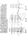
- Figures 1A to 1C demonstrate three different C-arm (x-ray) views in
the lumbar transforaminal endoscopic approach to the disc.
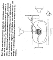
- Figure 2 demonstrates the approach needle trajectory to
annular window through a specific skin window determined in the
preferred methodology in transforaminal endoscopic lumbar
surgery.
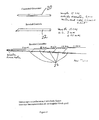
- Figure 3 presents a transforaminal endoscopic excision
technique for a paramedian disc herniation.
- Figure 4 presents a view of a disc and its adjacent
vertebrae.
- Figure 5 demonstrates the preferred transforaminal
endoscopic method in alleviated nerve compression in the foramen
and the lateral recess.
- Figure 5a shows the annular floor of the foramen is being
removed using forceps.
- Figure 5b shows the foraminal bony roof overhang is being
ablated using the Holmium-Yag laser.
- Figure 6 presents a semi-tubular spreader, with fish mouthed
end, and solid rod dilators.
- Figure 7 presents a flat blade spreader.
- Figure 8 presents tools to excavate the intervertebral disc
space.
- Figure 9 presents cylindrical tools used to create a working
channel from the skin window into the foraminal annular window.
- Figures 10 and 11 present bone graft materials used in the
preferred embodiment of the present invention.
-
Detailed Description of the Invention
-
According to the present invention, there is disclosed a
method and apparatus for performing percutaneous spinal
transforaminal endoscopic interbody fusion using modular discoid
shaped graft components.
-
In the following description, for the purposes of
explanation, specific devices, component arrangements and
construction details are set forth in order to provide a more
thorough understanding of the invention. It will be apparent to
those skilled in the art, however, that the present invention may
be practiced without these specifically enumerated details and
that the preferred embodiment can be modified so as to provide
other capabilities, such as the capability for the remote control
to operate with other devices. In some instances, well-known
structures and methods have not been described in detail so as
not to obscure the present invention unnecessarily.
-
Referring first to Figure 1, an approach to percutaneous
transforaminal endoscopic lumbar surgery is demonstrated. As
seen in A, B and C, the angle of the approach to the disc spaces
varies, depending upon the inclination of the targeted
intervertebral disc space. The general method of access utilizes
a small diameter cannula to create a soft tissue tunnel from an
opening in the skin window to the foraminal annular window or a
target area.
-
In the preferred embodiment of percutaneous transforaminal
surgery, the target is the foraminal annular window. As shown in
Figure 1, the initial step is to insert a needle following the
preferred path from the skin window to the foraminal annular
window. The preferred embodiment of the present invention
utilizes a large bore needle. It will be apparent to those of
skill in the art that the exact size and diameter of the needle
can vary and will depend on the particular treatment needs of the
patient.
-
Referring next to Figure 2, in the preferred mode, the
invention shows the percutaneous transforaminal endoscopic
approach in the axial view. However the invention can also be
used for minimally invasive procedures requiring other modified
approaches to the spine. The preferred method of localizing the
skin window is to plot the L5-S1 disc inclination in the lateral
c-arm projection, as demonstrated by the needle position in
Figure 1. Referring again to Figure 2, the skin window is
determined by measuring distance L from the approximate center of
the disc to the posterior skin surface. The distance L is also
the distance of skin window from the approximate saggital midline
of the patient. The cephalad-caudad location of the skin window
is found by the previously plotted disc inclination in the
lateral c-arm view.
-
Initially, a local anesthetic agent is used to infiltrate
the skin window, subcutaneous tissue and trajectory tract. As
noted above, a needle is then inserted from the skin window at
approximately 25-30 degrees from the frontal plane anteromedially
toward the foraminal annular window. It has been found that in a
typical patient, the an approximately six inch long, eighteen
gauge needle provides satisfactory treatment results. The exact
size of the needle may, as noted be smaller or larger, depending
on the needs of the individual patient.
-
Although the preferred embodiment of the method of the
present invention utilizes an angle of 25-30 degrees from the
frontal plane, it will be apparent to those skilled in the art
that a larger or smaller angle can be used in instances where the
specific anatomy or treatment needs of the patient require. For
example, the patient may have a disk herniation in an unusual
location which require access from a different orientation.
Alternatively, the patient may have a bone structure which
precludes inserting the needle at the preferred angle. In such
situations, the surgeon will have sufficient knowledge to
determine the most advantageous manner and orientation in which
to insert the needle.
-
The needle is advanced toward the target foraminal annular
window 12. In the postero-anterior view, the needle tip is placed
approximately in the center of the foraminal annular window
between the medial and lateral borders of the pedicle in the
foramen and then advanced through the full thickness of the
annulus.
-
A guide wire is then inserted through the needle channel.
-
The guide wire is advanced a sufficient distance to be adjacent
to the annulus and the needle is removed. In the preferred
embodiment, this distance is approximately one centimeter. A
bluntly tapered cannulated obturator 20 (see figure 9) is
inserted over the guide wire and firmly engages the annulus. The
guide wire is then removed.
-
The thickness of the annulus is infiltrated with local
anesthetic agent in four quadrants through the channels of the
obturator 20. Next, the through and through fenestration of the
annular window is achieved by advancing the bluntly tapered
obturator 20. After the taper of the obturator 20 is advanced
within the annulus, a beveled cannula 22 is placed over the
obturator 20. The cannula 22 is advanced until its beveled tip
straddles the annular opening. Then, the obturator 20 is
removed.
-
An operating endoscope is inserted into the beveled cannula
22. If the pathology is of intracanal intervertebral herniation,
refer to figure 3 for extraction method. Working spaces are
created in the annulus. Referring to Figure 3, a working oft
tissue tunnel is identified by the open arrow and the solid arrow
identifies a working cavity. The biting forceps are positioned
to open the herniation annular collar. Once the collar is opened,
the surgeon grasps the herniated nucleus fragment and pulls it
out via the previously established work spaces.
-
If the operating pathology calls for fusion, the targeted
disc space of the spine is distracted apart further using
progressively larger cannulae 22. During the disc space
distraction process, the full diameter of the cannulae 22 enters
the annular opening. Progressively greater distraction is
achieved using sequentially larger cannulae 22. In the preferred
embodiment the cannulae 22 are what are commonly known as fish
mouth cannulae.
-
When the disc space height distraction reaches anatomical
maximum, a semi tubular spreader 24 (see Figure 6) replaces the
largest sized cannula 22. The semi-tubular spreader 24 is opened
further using progressively larger solid bore rods 26 until the
spreader blades can achieve the desired opening. In the
preferred embodiment, the opening is typically in the range of
2.5mm-3.5mm. The exact size necessary will be dependent on the
anatomy and treatment needs of the patient. At this point, the
rotational orientation of the semi-tubular spreader 24 blades is
such that each blade engages the bony rims of the opposing
vertebra, and the opening is substantially parallel to the disc.
Up to this step, the fenestration made in the annulus remains
circular in shape.
-
Referring next to Figures 3 - 5 and 8, once the semi-tubular
spreader 24 is opened in this position, ablation of the nucleus
pulposus is initially undertaken using various hand rongeurs,
curettes, rake, shaver 30(4) and negative pressure devices. The
cartilaginous end-plate and the adjacent nucleus require a more
aggressive T-shaped configured debrider 30(2). The T-shaped
debriders 30(2), rake and other attachments can be operated by
hand or attached to a low speed, high torque power source. The
softer central nucleus pulposus removal may be achieved by using
a motorized shaver. In the surgical process for an acutely
herniated disc, the motorized shaver will debride the posterior
nucleus and remove unstable nucleus material from the herniation
path. The annular collar may be divided by using a cutting
forcep to perform a partial annulectomy in order to access
extended nucleus material in the epidural space. The side walls
of the annular channel may be further widened and medialized by
using a Holmium-Yag laser.
-
In the methodology of the invention, when the disc removal
has reached its desired limits and the selected amount of the
nucleus pulposus and cartilagenous end plate have been removed,
the excavated cavity will have roughly in the shape of a biconvex
and round disc.
-
The annular opening thus far is circular in its gross
dimensions. Referring next to Figure 7, the shape of the circular
annular fenestration is changed, in the subsequent steps, to an
angular (i.e., substantially rectangular) opening by the unique
methodology of the present invention. In the preferred
embodiment, the circular shaped opening is changed to a more
angular opening in the shape of a square or rectangle. The
angular shaped opening wastes no distracted disc space height
dimension and will accept the angular graft components for
maximum size and contact surfaces between the graft and the host
bed.
-
Next, a flat blade spreader 28, with blades that are
slightly wider than those of the semi-tubular spreader 24, is
inserted into the slot of the semi tubular spreader 24(1). The
two embraced spreaders 24 and 28 are then rotated through an
angle so that the flat blades are oriented substantially
cephalad-caudad. In the preferred embodiment of the present
invention, the spreaders are rotated through an angle of
approximately 90 degrees. While the two spreaders are
intertwined, the flat blade spreader 28 is opened moderately and
the semi tubular spreader 24 is removed. The flat blade spreader
28 is then opened to its maximum width, using a passive spreading
technique. This can be achieved by using progressively thicker
rectangular shaped distractor. The opened sides of the tunnel
created by the flat blade spreader are covered by attaching cover
blades both on the cephadad and the caudad end of the tunnel. The
covers blades are incorporated to retract soft tissue and exiting
nerve away from the tunnel proper. Several cover attachment
mechanisms are entertained. One is that of an attachment tunnel
on the outside surface of the flat blade. Other methods of
attachment mechanism include clasps and screw-ons. The enclosed
tunnel makes transit of the graft components free of entanglement
risks in the soft tissue.
-
Referring next to the implant/filler material shown in
Figure 10, multiple shallow perforations are made in the
subchondral bone of both end-plates to allow for the entry of a
blood supply for the fusion process.
-
Referring next to Figure 11, after completion of the above
preparations, introduction of the optimally sized modular discoid
shaped bone graft components from the outside of the skin surface
into the disc space is carried out. The preferred method uses at
least two pieces of modular discoid graft components. The first
piece is inserted and pushed as anteriorly as possible against
the interior of the anterior annulus. Gradual seating of the
graft is made possible by using various contoured impactors.
Once the first graft clears the tips of the flat blade spreader,
the second graft is inserted. For disc space of large size, a
third graft component, rectangular in shape can be introduced
between the first two graft components.
-
The graft to be inserted should have the largest possible
surface area and height to take advantage of the maximum possible
contact area with the opposing host end-plates. The bone graft
material should be tall enough so that the graft end-plate
surfaces are under compression. The ideal vertebral interbody
graft shape is that of a disc. Since the tunnel from the skin
into the disc space is very limited in height and width, it is
preferred to modularize the whole discoid shape into two or more
components to facilitate the passage of the material through the
relatively smaller tunnel.
-
After the insertion of the graft material, osteoconductive
and osteoinductive supplementary agents in the form of paste,
jelly or sponge can also be inserted to fill any small crevices
or voids that remain in the target intervertebral disc space.
-
It will be apparent to those skilled in the art that the
foregoing description is for illustrative purposes only, and that
various changes and modifications can be made to the present
invention without departing from the overall spirit and scope of
the present invention. The full extent of the present invention
is defined and limited only by the following claims.
-
Figure 1 shows skin window and c-arm landmarks for lumbar
transforaminal access. Figure 1A shows annular foraminal windows, dotted
areas. Transverse skin lines bisect discs and intersect mid-saggital line. Figure
1B shows an L5-S1 needle trajectory in line with disc inclination. Figure 1C
shows Ferugson c-arm view of L5-S1 disc, where needle trajectory bisects disc.
The procedure of Figure 2 is in the specific embodiment carried out under
conscious sedation and local anaesthesia. Free hand, biplane c-arm guidance is
used. For skin window localisation, length L may be determined in lateral c-arm
projection from disc centre to posterior skin surface. Metal rule may then
be marked segment L from below skin surface to tip. Length L may be used as
the lateral location of the skin window from the midline. Figure 3 shows a
posterolateral approach removing herniated disc. Figure 4 shows a
posterolateral approach using a laser to cut the base of the annulus. Figure 5B
shows use of a Holmium-YAG laser. In Figure 6, the blade length for the
semi-tubular spreader may be 15cm. The semi-tubular spreader may have an
outer diameter of 9, 10, 11 or 12mm, for example. The solid rod dilator may
have an outer diameter of 9, 10, 11, 12, 13 or 14mm, for example. Thus, it
would be appreciated that Figure 6 is a view of semi-tubular spreader and solid
rod dilators. The flat blade spreader may have a cover sheet 100 as shown in
Figure 7. Figure 8 shows tools for posterolateral endoscopic nucleus pulposis
and a vertebral end plate debrider. Figure 9 shows an endoscopic
transforaminal interbody fusion insertion instrumentation. In one example, the
obturator 20 has a length of 15cm, an outside diameter of 6mm. The bevelled
cannula to fit around the obturator may have a length of 15cm, outer diameter
of 7mm. Increasingly large cannulae may have outer diameters of 8, 9, 10 and
11mm. As shown in Figure 10, the lumbar intervertebral biological implant for
fusion may have an angular lattice, lattice tubes, and/or may be implanted in
halves for easier insertion. Additional graft material may be placed in a
midline gap. As shown in Figure 11, for a spine intervertebral disc space graft
shape and configuration, this may be discoid in shape and modular discoid
components may be used to construct the shape of the disc space.