EP1468842A1 - Embossing,stamping and/or pressing character and method for manufacturing the same - Google Patents
Embossing,stamping and/or pressing character and method for manufacturing the same Download PDFInfo
- Publication number
- EP1468842A1 EP1468842A1 EP04356052A EP04356052A EP1468842A1 EP 1468842 A1 EP1468842 A1 EP 1468842A1 EP 04356052 A EP04356052 A EP 04356052A EP 04356052 A EP04356052 A EP 04356052A EP 1468842 A1 EP1468842 A1 EP 1468842A1
- Authority
- EP
- European Patent Office
- Prior art keywords
- sole
- support
- punch
- stamping
- cutting
- Prior art date
- Legal status (The legal status is an assumption and is not a legal conclusion. Google has not performed a legal analysis and makes no representation as to the accuracy of the status listed.)
- Withdrawn
Links
Images


Classifications
-
- B—PERFORMING OPERATIONS; TRANSPORTING
- B21—MECHANICAL METAL-WORKING WITHOUT ESSENTIALLY REMOVING MATERIAL; PUNCHING METAL
- B21D—WORKING OR PROCESSING OF SHEET METAL OR METAL TUBES, RODS OR PROFILES WITHOUT ESSENTIALLY REMOVING MATERIAL; PUNCHING METAL
- B21D22/00—Shaping without cutting, by stamping, spinning, or deep-drawing
- B21D22/02—Stamping using rigid devices or tools
-
- B—PERFORMING OPERATIONS; TRANSPORTING
- B44—DECORATIVE ARTS
- B44B—MACHINES, APPARATUS OR TOOLS FOR ARTISTIC WORK, e.g. FOR SCULPTURING, GUILLOCHING, CARVING, BRANDING, INLAYING
- B44B5/00—Machines or apparatus for embossing decorations or marks, e.g. embossing coins
- B44B5/02—Dies; Accessories
- B44B5/026—Dies
Definitions
- the invention relates to a stamping character, cutting and / or crimping comprising a punch and / or a matrix and a method of manufacturing such a character.
- a character is used, for example, in a car dealership or in the assembly department of a large surface specialized in automotive accessories for make vehicle number plates automobiles according to the registration number assigned to each vehicle.
- Several characters are arranged side by side on a frame to form a chain of characters.
- FR-A-2 753 400 It is known, for example from FR-A-2 753 400, to equip a steel stamping character of return means elastic in open position. It is also known to FR-A-2 808 731 to produce a stamping character, the punch and the support to which it is associated are molded together by injection of a plastic material strongly loaded with reinforcing fibers. We also know of FR-A-2 680 343 an articulated character in which the respective supports of the punch and the die are molded, while the punch and the die are glued on these parts.
- the body of the punch or the matrix, which forms the embossing relief must be designed and manufactured according to the support to which it must be associated, this support depending in practice on the stamping machine to be used, whether it is a traveling composter or machine stamping with articulated characters.
- the punch body and die must be manufactured in relatively small specific series, which increases their cost price.
- these bodies are made by machining of metal or composite material, so that any additional operation of adaptation to their support significantly increases their manufacturing time and increases their cost price.
- the thickness of the metal plate in which is machined the punch is generally 6 mm
- the thickness of the metal plate in which is machined a die is usually 8mm because the die must have higher mechanical strength. It it follows that two types of metal plates, which complicates the manufacture of this kind of material.
- the invention relates to a character stamping, cutting or crimping which includes a punch and / or die capable of being each mounted on a support by means of which they are moved or held in place to stamp, cut and / or crimp a plate or sheet material, especially for a plate mineralogical or signage, this punch and / or this matrix each comprising a body defining their relief stamping or cutting.
- This character is characterized by what the punch and / or the die also includes a sole on which the aforementioned body is mounted and which is provided with removable mounting means on the support.
- the punch and / or the matrix of the character according to the invention is bi-partite, with a body in machined metal and a sole allowing the mounting of this body on a support, provides that the means of mounting the punch and / or the die on the support, which depend in practice on the type of this support, can be provided on sole only, machined metal body having the same general shape for all punches and all matrices, regardless of the type of support.
- the sole is an interface that allows to adapt the body of the punch and / or the die to support to use, this body having a standard shape.
- the body of the punch or the die can be mounted permanently, in particular glued or set, on the sole.
- means are provided blocking by cooperation of the aforementioned body shapes on the sole.
- these blocking means by cooperation of shapes can be associated with the collage of body on the sole.
- the matrix M represented in FIGS. 1 to 4 comprises a body 10 produced in a steel plate of thickness e equal to approximately 6 mm and defining an imprint 12 intended to cooperate with an imprint 62 formed in a body 60 of steel and of same thickness e belonging to a punch P.
- the matrix M also includes a molded sole 20 by injection of polyamide loaded with reinforcing fibers, especially in glass or carbon fibers.
- the material of the sole 20 can be any plastic material sufficiently resistant and easily moldable.
- the body 10 is mounted on the sole 20 while being engaged in a volume V 20 defined between two end edges 22 and 24 which have a thickness e 'greater than the thickness e ''of the sole 20 at the volume V 20 .
- the arrow F 1 represents the movement of placing the body 10 on the sole 20.
- the sole 20 is flat.
- the face 14 of the body 10 facing the sole 20 in the representation of FIG. 1 is also flat, which allows the body 10 to be optionally bonded to the sole 20.
- the edge 22 is provided with two rounded projections 26 and 28, while the edge 24 is provided with a projection rounded 30.
- the body 10 is provided with two rounded notches 16 and 18 of shapes adapted to receive the projections 26 and 28.
- the body 10 is also provided with a notch, not shown, sized and arranged to receive the projection 30 when projections 26 and 28 are engaged in notches 16 and 18.
- the notches provided on the body 10 and the projections provided on the sole 20 make it possible to immobilize the body 10 on the sole 20 by cooperation of shapes.
- the edge 22 is also provided with a projection 32 oriented opposite the volume V 20 , that is to say extending from the outer edge 22a of the edge 22.
- the edge 24 is provided a projection 34 which extends from its outer edge 24 a , opposite the volume V 20 .
- the projections 32 and 34 and the shape of the edges 22a and 24a allow to set place and immobilize the matrix M on a support S belonging to a composter with vertical movement.
- the support S is provided with two edges 82 and 84 in which are defined notches 92 and 94 of form adapted to receive projections 32 and 34 respectively of the sole 20 of each matrix M, M 'or equivalent.
- the installation of projections 32 and 34 in the notches 92 and 94 allows the dies M and M 'to be held in position on the support S.
- the inner edges 82a and 84a of the borders 82 and 84 are planar, as are edges 22a and 24a of the sole 20, which allows a clearance between these edges.
- these edges can be in contact, which contributes to the immobilization by cooperation of forms of each matrix M, M 'or equivalent on the support S, and this removably.
- each matrix M therefore makes it possible to constitute the interface between each steel block 10 and the support S, the sole 20 of a matrix M being in practice interposed between the body 10 of this matrix and the support S when this matrix is mounted on this support.
- the shape of the edges 82 and 84 of the support S can vary from one composting machine to another.
- the sole 20 allows the body 10 to be adapted to the exact type of support S and therefore to manufacture the bodies 10 in large quantities, regardless of the exact type of composting machine used, these bodies being obtained by machining plates of metal or composite material.
- the soles 20 are injection molded plastic taking into account the geometry of the support S used. As shown in Figures 6 to 10, this geometry is very variable and the shape of the soles 20 is then adapted to the shape of the borders 82 and the like of the media in question.
- the shape of the projections 26 and 28 is kept for all soles 20 because the shape of the body 10 does not change at their notches 16 and 18 respectively. The same goes for the opposite edge 24 of the soles 20 which is not shown in Figures 6 to 9.
- the support S can be provided with a pin 192 intended to be introduced into a through hole 132 formed in the border 22 of the sole 20.
- the edge 82 can be provided with a projection 292 while the edge 22 of the sole 20 is provided with a notch 232 of form corresponding.
- the edge 382 of the support S can be provided with teeth 392 suitable for cooperate with teeth 332 of corresponding shape provided on border 22.
- the border 482 of the support S can be provided with an elongated rib 492, while the edge 22 of the sole 20 is provided with a oblong light of corresponding shape 432.
- each matrix M on the support correspondent can have any suitable form depending, in practice, on the form chosen for the support S.
- the sole 20 can be provided, on its face 20 b facing away from the volume V 20 , with a mark 21 making it possible to identify the alphanumeric character which can be achieved thanks to this matrix.
- another reference 23 may be provided on this face 20 b to indicate the identity of the manufacturer of the matrix M or of the end user, for example a chain of large surfaces specialized in automotive equipment.
- the marks 21 and 23 are obtained by molding during the manufacture of the sole 20, without the need for rework in machining.
- the punch P shown in FIG. 5 also includes a sole 70 of the same type as the sole 20 of the corresponding matrix, this sole 70 being provided with projections 26 ′ and 28 ′ and with a projection provided on the opposite edge adapted to cooperate. with notches 66, 68 and with a not shown notch provided on the two opposite edges of the body 60.
- the sole 70 is further provided with projections 32 'and 34' which extend from straight edges 22 ' a and 24 has and have the same function as the projections 32 and 34 of the sole 20.
- the sole 70 of the punch creates an interface between the body 60 and the support, not shown, on which it must be mounted.
- the marks can be provided on the outer face of this sole, that is to say the face opposite the body 60.
- soles 20 and 70 can be identical.
- the invention is not limited to characters intended to be mounted in a movement stamping machine essentially vertical but can be used as shown in Figure 10, with articulated characters.
- the support S of the matrix M is then articulated on the support S 'of the punch P, while the soles 20 and 70 are respectively inserted between the bodies 10 and 60 and supports S and S '.
- the invention is not limited to characters but is applicable to die-cut characters a colored PVC adhesive sheet affixed to the face back of a transparent plastic plate, for example of PMMA.
- a transparent plastic plate for example of PMMA.
- such character which forms a punch P has its body 60 provided with ribs or cutting edges 60a instead of one footprint.
- This body must also be mounted on a support, for which one can use a sole 70 having the same geometry and the same function as that of the first embodiment.
- the invention allows weight gain.
- the body length 10 or 60 of a character according to the invention is less than the total length of a metallic character provided with means of mounting on a support. It follows that the risks of deformation of the body during a hardening heat treatment are minimized compared to those of known characters.
- the invention has been shown during its implementation for the production of license plates. She is however applicable to the manufacture of other plates bearing alphanumeric characters, in particular of nameplates.
Abstract
Description
L'invention a trait à un caractère d'estampage, de découpe et/ou de sertissage comprenant un poinçon et/ou une matrice et à un procédé de fabrication d'un tel caractère.The invention relates to a stamping character, cutting and / or crimping comprising a punch and / or a matrix and a method of manufacturing such a character.
Un caractère est utilisé, par exemple, dans une concession automobile ou au rayon « montage » d'une grande surface spécialisée dans les accessoires automobiles pour réaliser des plaques minéralogiques de véhicules automobiles en fonction du numéro d'immatriculation attribué à chaque véhicule. Plusieurs caractères sont disposés côte à côte sur un cadre afin de former une chaíne de caractères.A character is used, for example, in a car dealership or in the assembly department of a large surface specialized in automotive accessories for make vehicle number plates automobiles according to the registration number assigned to each vehicle. Several characters are arranged side by side on a frame to form a chain of characters.
Il est connu, par exemple de FR-A-2 753 400, d'équiper un caractère d'estampage en acier de moyens de rappel élastique en position ouverte. Il est également connu de FR-A-2 808 731 de réaliser un caractère d'estampage dont le poinçon et le support auquel il est associé sont moulés ensemble par injection d'une matière plastique fortement chargée en fibres de renfort. On connaít par ailleurs de FR-A-2 680 343 un caractère articulé dans lequel les supports respectifs du poinçon et de la matrice sont moulés, alors que le poinçon et la matrice sont collés sur ces pièces.It is known, for example from FR-A-2 753 400, to equip a steel stamping character of return means elastic in open position. It is also known to FR-A-2 808 731 to produce a stamping character, the punch and the support to which it is associated are molded together by injection of a plastic material strongly loaded with reinforcing fibers. We also know of FR-A-2 680 343 an articulated character in which the respective supports of the punch and the die are molded, while the punch and the die are glued on these parts.
Dans ces matériels connus, le corps du poinçon ou de la matrice, qui forme le relief d'estampage, doit être conçu et fabriqué en fonction du support auquel il doit être associé, ce support dépendant en pratique de la machine d'estampage à utiliser, qu'il s'agisse d'un composteur à mouvement de translation ou d'une machine d'estampage à caractères articulés. Il en résulte que les corps de poinçon et de matrice doivent être fabriqués en séries spécifiques relativement petites, ce qui augmente leur prix de revient. En outre, ces corps sont réalisés par usinage de métal ou de matériau composite, de sorte que toute opération supplémentaire d'adaptation à leur support rallonge de façon significative leur temps de fabrication et augmente leur prix de revient. Enfin, dans les systèmes connus, l'épaisseur de la plaque de métal dans laquelle est usiné le poinçon est généralement de 6 mm, alors que l'épaisseur de la plaque de métal dans laquelle est usinée une matrice est généralement de 8 mm, car la matrice doit présenter une résistance mécanique supérieure. Il en résulte qu'il convient d'approvisionner deux types de plaques de métal, ce qui complexifie la fabrication de ce genre de matériel.In these known materials, the body of the punch or the matrix, which forms the embossing relief, must be designed and manufactured according to the support to which it must be associated, this support depending in practice on the stamping machine to be used, whether it is a traveling composter or machine stamping with articulated characters. As a result, the punch body and die must be manufactured in relatively small specific series, which increases their cost price. In addition, these bodies are made by machining of metal or composite material, so that any additional operation of adaptation to their support significantly increases their manufacturing time and increases their cost price. Finally, in systems known, the thickness of the metal plate in which is machined the punch is generally 6 mm, while the thickness of the metal plate in which is machined a die is usually 8mm because the die must have higher mechanical strength. It it follows that two types of metal plates, which complicates the manufacture of this kind of material.
Des problèmes similaires se posent avec les caractères ou outils de découpe utilisés pour former, par découpe d'une feuille de polychlorure de vinyle (PVC) coloré apposée sur la face arrière d'une plaque de polymétacrylate de méthyle (PMMA) transparente, des caractères alphanumériques.Similar problems arise with characters or cutting tools used to form, by cutting a sheet of colored polyvinyl chloride (PVC) affixed to the rear side of a polymethacrylate plate methyl (PMMA) transparent, characters Alphanumeric.
Les mêmes inconvénients se posent pour la fabrication de plaques signalétiques.The same drawbacks arise for manufacturing nameplates.
C'est à ces inconvénients qu'entend plus particulièrement remédier l'invention en proposant un caractère d'estampage ou de découpe dont la fabrication peut être simplifiée et optimisée par rapport aux matériels connus, alors qu'il présente de grandes possibilités d'adaptation sur des machines à estamper de types variés.It is to these disadvantages that most particularly remedy the invention by proposing a stamping or cutting character, the manufacture of which can be simplified and optimized with respect to materials known, while it presents great possibilities adaptation on stamping machines of various types.
Dans cet esprit, l'invention concerne un caractère d'estampage, de découpe ou de sertissage qui comprend un poinçon et/ou une matrice aptes à être montés chacun sur un support au moyen duquel ils sont déplacés ou maintenus en place pour emboutir, découper et/ou sertir une plaque ou un matériau en feuille, notamment pour une plaque minéralogique ou signalétique, ce poinçon et/ou cette matrice comprenant chacun un corps définissant leur relief d'estampage ou de découpe. Ce caractère est caractérisé en ce que le poinçon et/ou la matrice comprend également une semelle sur laquelle est monté le corps précité et qui est pourvue de moyens de montage amovible sur le support.In this spirit, the invention relates to a character stamping, cutting or crimping which includes a punch and / or die capable of being each mounted on a support by means of which they are moved or held in place to stamp, cut and / or crimp a plate or sheet material, especially for a plate mineralogical or signage, this punch and / or this matrix each comprising a body defining their relief stamping or cutting. This character is characterized by what the punch and / or the die also includes a sole on which the aforementioned body is mounted and which is provided with removable mounting means on the support.
Le fait que le poinçon et/ou la matrice du caractère conforme à l'invention est bi-partite, avec un corps en métal usiné et une semelle permettant le montage de ce corps sur un support, permet de prévoir que les moyens de montage du poinçon et/ou de la matrice sur le support, qui dépendent en pratique du type de ce support, peuvent être prévus sur la semelle uniquement, le corps en métal usiné ayant la même forme générale pour tous les poinçons et toutes les matrices, indépendamment du type du support. En d'autres termes, la semelle est une interface qui permet d'adapter le corps du poinçon et/ou de la matrice au support à utiliser, ce corps ayant une forme standard.The fact that the punch and / or the matrix of the character according to the invention is bi-partite, with a body in machined metal and a sole allowing the mounting of this body on a support, provides that the means of mounting the punch and / or the die on the support, which depend in practice on the type of this support, can be provided on sole only, machined metal body having the same general shape for all punches and all matrices, regardless of the type of support. In in other words, the sole is an interface that allows to adapt the body of the punch and / or the die to support to use, this body having a standard shape.
Selon des aspects avantageux mais non obligatoires de l'invention, un caractère peut incorporer une ou plusieurs des caractéristiques suivantes, prises dans toute combinaison techniquement envisageable :
- Le poinçon et la semelle comprennent chacun un corps formant relief d'estampage ou de découpe et une semelle de montage amovible sur un support correspondant. Dans ce cas, on peut prévoir que les corps du poinçon et de la semelle sont formés dans des plaques de métal de mêmes épaisseurs, ce qui facilite l'approvisionnement d'un centre de fabrication de tels caractères.
- La semelle est en matière plastique moulée, notamment en polyamide chargé en fibres de renfort. La fabrication de la semelle par moulage permet d'obtenir de grandes quantités de semelles à faible coût et de former les moyens de montage amovible sur le support également par moulage, et non pas par usinage comme ce serait le cas avec des poinçons ou des matrices monoblocs en métal. Ceci s'avère très avantageux en termes économiques.
- Les moyens de montage comprennent des reliefs adaptés pour coopérer avec des reliefs de formes correspondantes prévus sur le support pour bloquer la semelle sur le support par coopération de formes.
- La semelle porte, sur un côté destiné à être orienté vers le support lorsque la semelle est montée sur celui-ci, un repère obtenu par moulage lors de la fabrication de la semelle.
- The punch and the sole each comprise a body forming a stamping or cutting relief and a removable mounting sole on a corresponding support. In this case, provision can be made for the bodies of the punch and of the sole to be formed from metal plates of the same thickness, which facilitates the supply of a center for manufacturing such characters.
- The sole is made of molded plastic, in particular of polyamide loaded with reinforcing fibers. The manufacture of the sole by molding makes it possible to obtain large quantities of soles at low cost and to form the removable mounting means on the support also by molding, and not by machining as would be the case with punches or dies. metal monoblocks. This is very advantageous in economic terms.
- The mounting means include reliefs adapted to cooperate with reliefs of corresponding shapes provided on the support to block the sole on the support by cooperation of shapes.
- The sole carries, on one side intended to be oriented towards the support when the sole is mounted thereon, a mark obtained by molding during the manufacture of the sole.
Selon un premier mode de réalisation de l'invention, le corps du poinçon ou de la matrice peut être monté de façon permanente, notamment collé ou serti, sur la semelle. Selon un autre mode de réalisation, il est prévu des moyens de blocage par coopération de formes du corps précité sur la semelle. En variante, ces moyens de blocage par coopération de formes peuvent être associés au collage du corps sur la semelle.According to a first embodiment of the invention, the body of the punch or the die can be mounted permanently, in particular glued or set, on the sole. According to another embodiment, means are provided blocking by cooperation of the aforementioned body shapes on the sole. As a variant, these blocking means by cooperation of shapes can be associated with the collage of body on the sole.
L'invention concerne également un procédé de
fabrication d'un caractère tel que précédemment décrit et,
plus spécifiquement, un procédé qui comprend des étapes
consistant à :
L'invention sera mieux comprise et d'autres avantages de celle-ci apparaítront plus clairement à la lumière de la description qui va suivre de sept modes de réalisation de caractères d'estampage conformes à son principe, donnée uniquement à titre d'exemple et faite en référence aux dessins annexés dans lesquels :
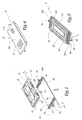
- la figure 1 est une vue en perspective éclatée de la matrice d'un caractère d'estampage conforme à l'invention ;
- la figure 2 est une représentation schématique de principe en perspective de la mise en place de la matrice de la figure 1 sur un support d'un composteur à mouvement rectiligne utilisé pour la fabrication de plaques minéralogiques ;
- la figure 3 est une coupe selon le plan III à la figure 2 ;
- la figure 4 est une vue de la matrice dans le sens de la flèche IV à la figure 1, cette matrice étant assemblée ;
- la figure 5 est une vue en perspective du poinçon du caractère d'estampage dont la matrice est représentée aux figures 1 à 4 ;
- les figures 6 à 9 sont des représentations schématiques partielles en perspective éclatée de parties de caractères conformes à des deuxième, troisième, quatrième et cinquième modes de réalisation de l'invention et de parties de supports associés ;
- la figure 10 est une coupe analogue à la figure 3 pour un caractère d'estampage conforme à un sixième mode de réalisation, du type « caractère articulé » et
- la figure 11 est une vue analogue à la figure 1 pour un caractère conforme à un septième mode de réalisation de l'invention.
- Figure 1 is an exploded perspective view of the die of a stamping character according to the invention;
- Figure 2 is a schematic representation in principle in perspective of the establishment of the matrix of Figure 1 on a support of a composter with rectilinear movement used for the manufacture of license plates;
- Figure 3 is a section on plane III in Figure 2;
- Figure 4 is a view of the matrix in the direction of arrow IV in Figure 1, this matrix being assembled;
- Figure 5 is a perspective view of the punch of the stamping character whose matrix is shown in Figures 1 to 4;
- FIGS. 6 to 9 are partial schematic representations in exploded perspective of parts of characters in accordance with second, third, fourth and fifth embodiments of the invention and parts of associated supports;
- FIG. 10 is a section similar to FIG. 3 for a stamping character in accordance with a sixth embodiment, of the “articulated character” type and
- Figure 11 is a view similar to Figure 1 for a character according to a seventh embodiment of the invention.
La matrice M représentée aux figures 1 à 4 comprend un
corps 10 réalisé dans une plaque d'acier d'épaisseur e
égale à environ 6 mm et définissant une empreinte 12
destinée à coopérer avec une empreinte 62 formée dans un
corps 60 en acier et de même épaisseur e appartenant à un
poinçon P.The matrix M represented in FIGS. 1 to 4 comprises a
La matrice M comprend également une semelle 20 moulée
par injection de polyamide chargé en fibres de renfort,
notamment en fibres de verre ou de carbone. En pratique, le
matériau constitutif de la semelle 20 peut être toute
matière plastique suffisamment résistante et aisément
moulable.The matrix M also includes a molded
Le corps 10 est monté sur la semelle 20 en étant
engagé dans un volume V20 défini entre deux bordures
d'extrémité 22 et 24 qui présentent une épaisseur e'
supérieure à l'épaisseur e'' de la semelle 20 au niveau du
volume V20. La flèche F1 représente le mouvement de mise en
place du corps 10 sur la semelle 20.The
Au niveau du volume V20, la semelle 20 est plane. La
face 14 du corps 10 tournée vers la semelle 20 dans la
représentation de la figure 1 est également plane, ce qui
permet de coller éventuellement le corps 10 sur la semelle
20.At the level of the volume V 20 , the sole 20 is flat. The
La bordure 22 est pourvue de deux saillies arrondies
26 et 28, alors que la bordure 24 est pourvue d'une saillie
arrondie 30.The
Le corps 10 est pourvu de deux encoches arrondies 16
et 18 de formes adaptées pour recevoir les saillies 26 et
28. Le corps 10 est également pourvu d'une encoche, non
représentée, dimensionnée et disposée pour recevoir la
saillie 30 lorsque les saillies 26 et 28 sont engagées dans
les encoches 16 et 18. The
Ainsi, les encoches prévues sur le corps 10 et les
saillies prévues sur la semelle 20 permettent d'immobiliser
le corps 10 sur la semelle 20 par coopération de formes.Thus, the notches provided on the
Le fait que le nombre des saillies 26, 28 ou 30 sur
les bordures 22 et 24 sont différents assure une fonction
de détrompage car le corps 10 ne peut pas être monté tête-bêche
sur la semelle 20.The fact that the number of
Dans ces conditions, il n'est pas indispensable de
coller le corps 10 sur la partie plane 20a de la semelle
20.In these conditions, it is not essential to
glue the
La bordure 22 est également pourvue d'une saillie 32
orientée à l'opposé du volume V20, c'est-à-dire s'étendant à
partir du bord externe 22a de la bordure 22. De même, la
bordure 24 est pourvue d'une saillie 34 qui s'étend à
partir de son bord externe 24a, à l'opposé du volume V20.The
Comme représenté à la figure 2, les saillies 32 et 34
et la forme des bords 22a et 24a permettent de mettre en
place et d'immobiliser la matrice M sur un support S
appartenant à un composteur à mouvement vertical.As shown in Figure 2, the
Dans la représentation de la figure 2, une seconde matrice M' correspondant au chiffre 8 est déjà montée sur le support S, alors que la matrice M correspond au chiffre 0. Pour le reste, les matrices M et M' sont identiques et leurs éléments constitutifs respectifs portent les mêmes références dans la présente description.In the representation of Figure 2, a second matrix M 'corresponding to figure 8 is already mounted on the support S, while the matrix M corresponds to the digit 0. For the rest, the matrices M and M 'are identical and their respective components carry the same references in this description.
Le support S est pourvu de deux bordures 82 et 84 dans
lesquelles sont définies des encoches 92 et 94 de forme
adaptée pour recevoir respectivement les saillies 32 et 34
de la semelle 20 de chaque matrice M, M' ou équivalente. La
mise en place des saillies 32 et 34 dans les encoches 92 et
94 permet le maintien en position des matrices M et M' sur
le support S. En outre, les bords intérieurs 82a et 84a des
bordures 82 et 84 sont plans, tout comme les bords 22a et
24a de la semelle 20, ce qui permet de ménager un jeu entre
ces bords. En variante, ces bords peuvent être en contact,
ce qui contribue à l'immobilisation par coopération de
formes de chaque matrice M, M' ou équivalente sur le
support S, et ce, de façon amovible.The support S is provided with two
La semelle 20 de chaque matrice M permet donc de
constituer l'interface entre chaque bloc 10 en acier et le
support S, la semelle 20 d'une matrice M étant en pratique
interposée entre le corps 10 de cette matrice et le support
S lorsque cette matrice est montée sur ce support.The sole 20 of each matrix M therefore makes it possible to
constitute the interface between each
Ainsi, lorsqu'il convient de composer un numéro de plaque d'immatriculation, il suffit de disposer sur le support S les matrices des caractères correspondants, comme représenté par la flèche F2 à la figure 2. Le montage des matrices M, M' et équivalentes sur le support S est amovible en ce sens que, après réalisation d'un jeu de plaques minéralogiques, les matrices sont retirées du support.Thus, when it is advisable to dial a license plate number, it suffices to have the matrices of the corresponding characters on the support S, as shown by the arrow F 2 in FIG. 2. The mounting of the matrices M, M ' and the like on the support S is removable in the sense that, after making a set of number plates, the dies are removed from the support.
La forme des bordures 82 et 84 du support S peut
varier d'une machine de compostage à une autre. La semelle
20 permet d'adapter le corps 10 au type exact du support S
et donc de fabriquer les corps 10 en grandes quantités,
indépendamment du type exact de la machine de compostage
utilisée, ces corps étant obtenus par usinage de plaques de
métal ou de matériau composite.The shape of the
Les semelles 20 sont moulées par injection de matière
plastique en tenant compte de la géométrie du support S
utilisé. Comme il ressort des figures 6 à 10, cette
géométrie est très variable et la forme des semelles 20 est
alors adaptée à la forme des bordures 82 et équivalentes
des supports en question.The
Par ailleurs, la forme des saillies 26 et 28 est
conservée pour toutes les semelles 20 car la forme des
corps 10 ne change pas au niveau de leurs encoches
respectives 16 et 18. Il en va de même du côté de la
bordure opposée 24 des semelles 20 qui n'est pas
représentée sur les figures 6 à 9.Furthermore, the shape of the
Comme représenté à la figure 6, le support S peut être
pourvu d'un pion 192 destiné à être introduit dans un
orifice traversant 132 ménagé dans la bordure 22 de la
semelle 20.As shown in Figure 6, the support S can be
provided with a
Comme représenté à la figure 7, le bord 82 peut être
pourvu d'une saillie 292 alors que la bordure 22 de la
semelle 20 est pourvue d'une encoche 232 de forme
correspondante.As shown in FIG. 7, the
Comme représenté à la figure 8, la bordure 382 du
support S peut être pourvue de dents 392 adaptées pour
coopérer avec des dents 332 de forme correspondante prévues
sur la bordure 22.As shown in Figure 8, the
Comme représenté sur la figure 9, la bordure 482 du
support S peut être pourvue d'une nervure allongée 492,
alors que la bordure 22 de la semelle 20 est pourvue d'une
lumière oblongue de forme correspondante 432.As shown in FIG. 9, the
Bien entendu, les exemples représentés sur les figures 6 à 9 ne sont pas limitatifs et les reliefs permettant l'immobilisation de chaque matrice M sur le support correspondant peuvent avoir toutes formes adaptées dépendant, en pratique, de la forme choisie pour le support S.Of course, the examples shown in the figures 6 to 9 are not limiting and the reliefs allowing immobilization of each matrix M on the support correspondent can have any suitable form depending, in practice, on the form chosen for the support S.
Comme il ressort plus particulièrement de la figure 4,
la semelle 20 peut être pourvue, sur sa face 20b orientée à
l'opposé du volume V20, d'un repère 21 permettant
d'identifier le caractère alphanumérique pouvant être
réalisé grâce à cette matrice.As can be seen more particularly from FIG. 4, the sole 20 can be provided, on its
De la même façon, un autre repère 23 peut être prévu
sur cette face 20b pour indiquer l'identité du fabricant de
la matrice M ou de l'utilisateur final, par exemple une
chaíne de grandes surfaces spécialisées dans les
équipements automobiles. Similarly, another
Les repères 21 et 23 sont obtenus par moulage lors de
la fabrication de la semelle 20, sans nécessité de reprise
en usinage.The
Le poinçon P représenté à la figure 5 comprend
également une semelle 70 du même type que la semelle 20 de
la matrice correspondante, cette semelle 70 étant pourvue
de saillies 26' et 28' et d'une saillie prévue sur le bord
opposé adaptées pour coopérer avec des encoches 66, 68 et
avec une encoche non représentée prévue sur les deux bords
opposés du corps 60. La semelle 70 est en outre pourvue de
saillies 32' et 34' qui s'étendent à partir de bords
rectilignes 22'a et 24'a et ont la même fonction que les
saillies 32 et 34 de la semelle 20.The punch P shown in FIG. 5 also includes a sole 70 of the same type as the sole 20 of the corresponding matrix, this sole 70 being provided with
Ainsi, comme la semelle 20 de la matrice, la semelle
70 du poinçon permet de créer une interface entre le corps
60 et le support non représenté sur lequel il doit être
monté.So like the sole 20 of the matrix, the sole
70 of the punch creates an interface between the
Comme pour la semelle 20, les repères peuvent être
prévus sur la face extérieure de cette semelle, c'est-à-dire
la face opposée au corps 60.As for sole 20, the marks can be
provided on the outer face of this sole, that is to say
the face opposite the
En pratique, les semelles 20 et 70 peuvent être
identiques.In practice, the
L'invention n'est pas limitée aux caractères destinés
à être montés dans une machine à estamper à mouvement
essentiellement vertical mais peut être utilisée, comme
représenté à la figure 10, avec des caractères articulés.
Le support S de la matrice M est alors articulé sur le
support S' du poinçon P, alors que les semelles 20 et 70
sont respectivement intercalées entre les corps 10 et 60 et
les supports S et S'.The invention is not limited to characters intended
to be mounted in a movement stamping machine
essentially vertical but can be used as
shown in Figure 10, with articulated characters.
The support S of the matrix M is then articulated on the
support S 'of the punch P, while the
L'invention n'est pas limitée aux caractères
d'estampage mais est applicable aux caractères de découpe
d'une feuille adhésive en PVC colorée apposée sur la face
arrière d'une plaque de matière plastique transparente, par
exemple de PMMA. Comme représenté à la figure 11, un tel
caractère qui forme un poinçon de découpe P a son corps 60
pourvu de nervures ou arêtes tranchantes 60a au lieu d'une
empreinte. Ce corps doit également être monté sur un
support, ce pour quoi on peut utiliser une semelle 70 ayant
la même géométrie et la même fonction que celle du premier
mode de réalisation.The invention is not limited to characters
but is applicable to die-cut characters
a colored PVC adhesive sheet affixed to the face
back of a transparent plastic plate, for
example of PMMA. As shown in Figure 11, such
character which forms a punch P has its
En pratique, on peut fabriquer de grandes quantités de
corps 10 ou 60 pourvus d'empreinte et monter ceux-ci, à la
demande, sur des semelles 20 ou 70, en fonction des
machines à équiper.In practice, large quantities of
Lors de la fabrication d'un caractère tel que
précédemment décrit, on comprend que l'on sélectionne une
semelle qui dépend de la géométrie du support S sur lequel
on envisage de monter le poinçon ou la matrice en question,
de telle sorte que ces reliefs de montage 32, 34, 32', 34',
132, 232, 332 ou 432 et équivalents soient adaptés aux
reliefs complémentaires 92, 94, 192, 292, 392, 492 ou
équivalents prévus sur ce support. Lorsque ce choix est
effectué, on assemble alors le corps du caractère et la
semelle par collage et/ou par coopération de formes des
reliefs 16, 26, 18, 28 et équivalents.When making a character such as
previously described, we understand that we select a
sole which depends on the geometry of the support S on which
we plan to mount the punch or die in question,
so that these mounting
Compte tenu du matériau de la semelle 20 ou 70, l'invention permet un gain de poids.Given the material of the sole 20 or 70, the invention allows weight gain.
En outre, la longueur du corps 10 ou 60 d'un caractère
conforme à l'invention est inférieure à la longueur totale
d'un caractère métallique pourvu de moyens de montage sur
un support. Il en résulte que les risques de déformation du
corps lors d'un traitement thermique de durcissage sont
minimisés par rapport à ceux des caractères connus.In addition, the
Les caractéristiques des différents modes de réalisation représentées peuvent être combinées entre elles dans le cadre de la présente invention. The characteristics of the different modes of shown achievements can be combined in the context of the present invention.
L'invention a été représentée lors de sa mise en oeuvre pour la fabrication de plaques minéralogique. Elle est cependant applicable à la fabrication d'autres plaques portant des caractères alphanumériques, notamment de plaques signalétiques.The invention has been shown during its implementation for the production of license plates. She is however applicable to the manufacture of other plates bearing alphanumeric characters, in particular of nameplates.
Claims (10)
Applications Claiming Priority (2)
| Application Number | Priority Date | Filing Date | Title |
|---|---|---|---|
| FR0304824A FR2853854B1 (en) | 2003-04-17 | 2003-04-17 | STAMPING, CUTTING AND / OR CRIMPING CHARACTER AND METHOD OF MANUFACTURING THE SAME |
| FR0304824 | 2003-04-17 |
Publications (1)
| Publication Number | Publication Date |
|---|---|
| EP1468842A1 true EP1468842A1 (en) | 2004-10-20 |
Family
ID=32893382
Family Applications (1)
| Application Number | Title | Priority Date | Filing Date |
|---|---|---|---|
| EP04356052A Withdrawn EP1468842A1 (en) | 2003-04-17 | 2004-04-15 | Embossing,stamping and/or pressing character and method for manufacturing the same |
Country Status (2)
| Country | Link |
|---|---|
| EP (1) | EP1468842A1 (en) |
| FR (1) | FR2853854B1 (en) |
Cited By (3)
| Publication number | Priority date | Publication date | Assignee | Title |
|---|---|---|---|---|
| GB2431617A (en) * | 2005-10-25 | 2007-05-02 | Samar T Ind | Machine for transfer printing using heat and pressure. |
| ES2291122A1 (en) * | 2006-05-24 | 2008-02-16 | Industrias Samar't, S.A. | Matrix to insert characters for enrollment perfected plates, has two bodies, male with projection and female with furrows with connection pieces and closing located in end of body and clamp with union in upper or lower part |
| ES2333758A1 (en) * | 2007-07-18 | 2010-02-26 | Industrias Samar't, S.A. | Chassis caracacacters and reversible fixing compositor (Machine-translation by Google Translate, not legally binding) |
Citations (9)
| Publication number | Priority date | Publication date | Assignee | Title |
|---|---|---|---|---|
| US1831434A (en) * | 1927-09-21 | 1931-11-10 | Stephen S Adams | Embossing machine |
| US1885385A (en) * | 1932-02-02 | 1932-11-01 | Cunningham Co M E | Die |
| FR2143626A1 (en) * | 1971-10-05 | 1973-02-09 | Bourette Adrien | |
| FR2597769A1 (en) * | 1986-04-29 | 1987-10-30 | Faab Ind | Characters for the manufacture of indicating and signalling plates by stamping (drawing), and corresponding composing table |
| US4733552A (en) * | 1982-07-21 | 1988-03-29 | Lefils Michel E | Multi-station punch/die press for progressive strip stock operations at variable index length |
| FR2680343A1 (en) | 1991-08-14 | 1993-02-19 | Fabricauto Sa | Tool for punching (embossing) characters on plates, in particular on registration plates for motor vehicles |
| FR2748222A1 (en) * | 1996-05-03 | 1997-11-07 | Brochut Jean Michel | Compositing plate for registration forms |
| FR2753400A1 (en) | 1996-09-13 | 1998-03-20 | Gravo Marque Trophees Coupes G | Figure stamp for vehicle number plates |
| FR2808731A1 (en) | 2000-05-10 | 2001-11-16 | Gravo Marque Trophees Coupes G | Character stamp esp for vehicle registration plate has moulded plastic die with high charge of reinforcing fibres |
-
2003
- 2003-04-17 FR FR0304824A patent/FR2853854B1/en not_active Expired - Fee Related
-
2004
- 2004-04-15 EP EP04356052A patent/EP1468842A1/en not_active Withdrawn
Patent Citations (9)
| Publication number | Priority date | Publication date | Assignee | Title |
|---|---|---|---|---|
| US1831434A (en) * | 1927-09-21 | 1931-11-10 | Stephen S Adams | Embossing machine |
| US1885385A (en) * | 1932-02-02 | 1932-11-01 | Cunningham Co M E | Die |
| FR2143626A1 (en) * | 1971-10-05 | 1973-02-09 | Bourette Adrien | |
| US4733552A (en) * | 1982-07-21 | 1988-03-29 | Lefils Michel E | Multi-station punch/die press for progressive strip stock operations at variable index length |
| FR2597769A1 (en) * | 1986-04-29 | 1987-10-30 | Faab Ind | Characters for the manufacture of indicating and signalling plates by stamping (drawing), and corresponding composing table |
| FR2680343A1 (en) | 1991-08-14 | 1993-02-19 | Fabricauto Sa | Tool for punching (embossing) characters on plates, in particular on registration plates for motor vehicles |
| FR2748222A1 (en) * | 1996-05-03 | 1997-11-07 | Brochut Jean Michel | Compositing plate for registration forms |
| FR2753400A1 (en) | 1996-09-13 | 1998-03-20 | Gravo Marque Trophees Coupes G | Figure stamp for vehicle number plates |
| FR2808731A1 (en) | 2000-05-10 | 2001-11-16 | Gravo Marque Trophees Coupes G | Character stamp esp for vehicle registration plate has moulded plastic die with high charge of reinforcing fibres |
Cited By (5)
| Publication number | Priority date | Publication date | Assignee | Title |
|---|---|---|---|---|
| GB2431617A (en) * | 2005-10-25 | 2007-05-02 | Samar T Ind | Machine for transfer printing using heat and pressure. |
| ES2304274A1 (en) * | 2005-10-25 | 2008-10-01 | Industrias Samar't, S.A. | Machine for transfer printing using heat and pressure. |
| GB2431617B (en) * | 2005-10-25 | 2009-07-15 | Samar T Ind | Machine for applying characters, logotypes, signs or distinctive marks on signs, licence plates or similar elements by heat transfer |
| ES2291122A1 (en) * | 2006-05-24 | 2008-02-16 | Industrias Samar't, S.A. | Matrix to insert characters for enrollment perfected plates, has two bodies, male with projection and female with furrows with connection pieces and closing located in end of body and clamp with union in upper or lower part |
| ES2333758A1 (en) * | 2007-07-18 | 2010-02-26 | Industrias Samar't, S.A. | Chassis caracacacters and reversible fixing compositor (Machine-translation by Google Translate, not legally binding) |
Also Published As
| Publication number | Publication date |
|---|---|
| FR2853854A1 (en) | 2004-10-22 |
| FR2853854B1 (en) | 2005-06-10 |
Similar Documents
| Publication | Publication Date | Title |
|---|---|---|
| EP0793835B1 (en) | Board with at least one built-in electronic element | |
| FR2920717A1 (en) | Covering element for inner panel of e.g. door, of motor vehicle, has coating including coating sheet fixed to base body provided with light guide, by overmolding, where support portion and light guide are made of single piece | |
| EP0847848B1 (en) | Article comprising a moulded body and an inlaid decorative element and process for its manufacture | |
| EP1468842A1 (en) | Embossing,stamping and/or pressing character and method for manufacturing the same | |
| FR2852730A1 (en) | OPERATING ELEMENT WITH LIGHT SYMBOL FROM BEHIND AND DIFFUSING SHEET | |
| FR3043035A1 (en) | GARNISHING ELEMENT COMPRISING BANDS OF OPAQUE WOVEN MATERIALS AND BANDS OF TRANSLUCENT MATERIAL | |
| EP3112954A1 (en) | Method for manufacturing clock components for timepieces | |
| FR2808731A1 (en) | Character stamp esp for vehicle registration plate has moulded plastic die with high charge of reinforcing fibres | |
| FR3068904B1 (en) | METHOD FOR MANUFACTURING FORK BLADE KNIFE AND FORGED BLADE KNIFE | |
| FR2842935A1 (en) | INFORMATION PANEL | |
| EP3679292B1 (en) | Method for making a colour screen for a motor vehicle lighting and/or signalling device | |
| FR2946628A1 (en) | METHOD FOR MANUFACTURING FOAM LAYING MEMBER FOR TRANSPORTING OBJECTS AND SETTING ELEMENT OBTAINED | |
| EP0776788B1 (en) | Method for applying indicia on a surface | |
| FR2853855A1 (en) | Shaping or cutting tool especially for licence plate symbols has transverse edges leaving tongues of sheet material to facilitate removal of inner areas | |
| EP3722128B1 (en) | Improved tailgate box assembly and tailgate skin | |
| FR3044590B1 (en) | DEVICE FOR CUSTOMIZING A VEHICLE BY MARKING | |
| FR2749525A1 (en) | Press for forming vehicle number plates | |
| FR2858837A1 (en) | RACK PUSH BUTTON OF A MOTOR VEHICLE STEERING SYSTEM | |
| FR2705265A1 (en) | Method of manufacturing a toothed wheel for a wiper control device, and toothed wheel thus produced. | |
| FR2460215A1 (en) | Vehicle wheel trim assembly - with metal cover secured over plastics body part of same configuration | |
| EP4112267A1 (en) | Painted bodywork part comprising a decorated pattern made by hot-marking | |
| FR2520643A1 (en) | Metal-coated resin pressing or moulding dies - using resin body to press its own metal coating | |
| FR3093041A1 (en) | Vehicle trim element comprising a partially overmolded coating layer | |
| FR2681570A1 (en) | Steering wheel for a motor vehicle with built-in document holder board | |
| FR2803354A1 (en) | BALANCING MASSELOT PARTICULARLY FOR VEHICLE WHEEL |
Legal Events
| Date | Code | Title | Description |
|---|---|---|---|
| PUAI | Public reference made under article 153(3) epc to a published international application that has entered the european phase |
Free format text: ORIGINAL CODE: 0009012 |
|
| AK | Designated contracting states |
Kind code of ref document: A1 Designated state(s): AT BE BG CH CY CZ DE DK EE ES FI FR GB GR HU IE IT LI LU MC NL PL PT RO SE SI SK TR |
|
| AX | Request for extension of the european patent |
Extension state: AL HR LT LV MK |
|
| STAA | Information on the status of an ep patent application or granted ep patent |
Free format text: STATUS: THE APPLICATION HAS BEEN WITHDRAWN |
|
| 18W | Application withdrawn |
Effective date: 20050304 |