EP1475122A2 - Catheter anchoring system - Google Patents
Catheter anchoring system Download PDFInfo
- Publication number
- EP1475122A2 EP1475122A2 EP04077158A EP04077158A EP1475122A2 EP 1475122 A2 EP1475122 A2 EP 1475122A2 EP 04077158 A EP04077158 A EP 04077158A EP 04077158 A EP04077158 A EP 04077158A EP 1475122 A2 EP1475122 A2 EP 1475122A2
- Authority
- EP
- European Patent Office
- Prior art keywords
- retainer
- adaptor
- catheter
- channel
- longitudinal
- Prior art date
- Legal status (The legal status is an assumption and is not a legal conclusion. Google has not performed a legal analysis and makes no representation as to the accuracy of the status listed.)
- Withdrawn
Links
Images


Classifications
-
- A—HUMAN NECESSITIES
- A61—MEDICAL OR VETERINARY SCIENCE; HYGIENE
- A61M—DEVICES FOR INTRODUCING MEDIA INTO, OR ONTO, THE BODY; DEVICES FOR TRANSDUCING BODY MEDIA OR FOR TAKING MEDIA FROM THE BODY; DEVICES FOR PRODUCING OR ENDING SLEEP OR STUPOR
- A61M25/00—Catheters; Hollow probes
-
- A—HUMAN NECESSITIES
- A61—MEDICAL OR VETERINARY SCIENCE; HYGIENE
- A61M—DEVICES FOR INTRODUCING MEDIA INTO, OR ONTO, THE BODY; DEVICES FOR TRANSDUCING BODY MEDIA OR FOR TAKING MEDIA FROM THE BODY; DEVICES FOR PRODUCING OR ENDING SLEEP OR STUPOR
- A61M25/00—Catheters; Hollow probes
- A61M25/01—Introducing, guiding, advancing, emplacing or holding catheters
- A61M25/02—Holding devices, e.g. on the body
- A61M2025/024—Holding devices, e.g. on the body having a clip or clamp system
-
- A—HUMAN NECESSITIES
- A61—MEDICAL OR VETERINARY SCIENCE; HYGIENE
- A61M—DEVICES FOR INTRODUCING MEDIA INTO, OR ONTO, THE BODY; DEVICES FOR TRANSDUCING BODY MEDIA OR FOR TAKING MEDIA FROM THE BODY; DEVICES FOR PRODUCING OR ENDING SLEEP OR STUPOR
- A61M25/00—Catheters; Hollow probes
- A61M25/01—Introducing, guiding, advancing, emplacing or holding catheters
- A61M25/02—Holding devices, e.g. on the body
- A61M2025/028—Holding devices, e.g. on the body having a mainly rigid support structure
-
- Y—GENERAL TAGGING OF NEW TECHNOLOGICAL DEVELOPMENTS; GENERAL TAGGING OF CROSS-SECTIONAL TECHNOLOGIES SPANNING OVER SEVERAL SECTIONS OF THE IPC; TECHNICAL SUBJECTS COVERED BY FORMER USPC CROSS-REFERENCE ART COLLECTIONS [XRACs] AND DIGESTS
- Y10—TECHNICAL SUBJECTS COVERED BY FORMER USPC
- Y10S—TECHNICAL SUBJECTS COVERED BY FORMER USPC CROSS-REFERENCE ART COLLECTIONS [XRACs] AND DIGESTS
- Y10S128/00—Surgery
- Y10S128/26—Cannula supporters
Abstract
Description
- The present invention relates in general to a percutaneous catheterization system, and, in particular, to a catheter anchoring system which securely interconnects an indwelling catheter with a tubing and securely anchors such interconnection to a patient's skin.
- Medical treatment of patients commonly involves the use of percutaneously inserted catheters to direct fluids directly into the bloodstream, a specific organ or an internal location of the patient, or to monitor vital functions of the patient. For instance, intra-arteriosus catheters are commonly used to direct fluids and/or medication directly into the bloodstream of the patient. Epidural catheters are commonly used to direct anesthesia into an epidural space to anesthetize a specific location of the patient. Intervascular catheters are commonly used to monitor arterial blood pressure.
- The fluid (e.g., parenteral liquid, medication or anesthesia) typically drains from a container positioned above the patient. The fluid flows through tubing and into an indwelling catheter. The catheter and fluid tubing are commonly removably attached by a conventional lure-type connector, such as the type described in U.S. Patent No. 4,224,937.
- In common practice, a health care provider, such as, for example, a nurse or doctor (for ease of description, as used herein the term "nurse" will refer to health care providers generally and will not be restrictive in meaning), uses adhesive or surgical tape to maintain the catheter in place on the skin of the patient. The connection between the tubing and the catheter is likewise maintained by use of tape.
- The nurse may also form a safety loop in the tubing so that any tension applied to the tubing does not directly pass to the catheter cannula, but rather is absorbed by the slack of the safety loop. The nurse typically loosely tapes the loop to the skin of the patient.
- This entire taping procedure takes several minutes of the valuable time of the health care provider. Furthermore, nurses commonly remove their gloves when taping because most nurse find such taping procedures difficult and cumbersome when wearing gloves.
- The catheterization process often requires frequent disconnection between the catheter and the fluid supply tube. For instance, intravenous catheterization is frequently maintained for several days, depending upon the condition of the patient. The catheter tubing is generally replaced every 24 to 48 hours in order to maintain the sterility of the fluid and the free-flow of the fluid through the tubing. A nurse must thus frequently change the tubing and retape the connection. Moreover, the tape, which secures the catheter to the skin of the patient, often covers the cannula insertion point. The nurse must remove the tape to inspect the insertion point for inflammation or infection, and must then repeat the above-described taping procedure.
- A great deal of valuable time is thus used in applying significant amounts of surgical tape to indwelling catheters. The frequent application and removal of surgical tape also commonly results in the excoriation of the skin of the patient in the area of the insertion.
- A number of catheterization systems have recently been developed which improve the stabilization of the catheter system and obviate the need for frequent application and removal of surgical tape. One such system is disclosed by U.S. Patent No. 5,192,273 issued to the present Applicant.
- The '273 patent discloses an adaptor which interconnects the catheter with a fluid supply tubing. The adaptor snaps into a base attached to the patient's skin by an adhesive pad. Specifically, a nurse presses the adaptor between upstanding legs of the base. Detents on the adaptor legs slide into corresponding annular grooves in the adaptor body to hold the adaptor to the base.
- Although the base holds the adaptor securely in place, a nurse may have difficulty positioning and aligning the annular grooves of the adaptor with the detents on the base. Exigent circumstances may further exacerbate the difficulties associated with properly positioning the adaptor onto the base. Some nurses and other health care providers may also have trouble determining how to engage the catheter adaptor with the base.
- The catheter anchoring system of the present invention provides an adaptor retainer which is not position or technique sensitive. That is, the nurse simply locates the catheter adaptor generally above the retainer, and presses the adaptor into the retainer. Engagement requires only coarse alignment of the adaptor with the retainer.
- In accordance with one aspect of the present invention, an anchoring system is provided for use with a catheter having an adaptor with at least one recess. The anchoring system has a retainer to receive the adaptor. The retainer includes a channel that extends through the retainer about a longitudinal axis. The channel is configured to receive at least a portion of the adaptor in a snap-fit manner. At least one projection on the retainer extends into the channel in a direction generally normal to the longitudinal axis. The projection has a longitudinal length so dimensioned to substantially equal the longitudinal length of the recess of the adaptor. The cooperation between the projection of the retainer and the recess of the adaptor inhibit longitudinal movement of the adaptor relative to the retainer.
- In accordance with another aspect of the present invention, an anchoring system includes a retainer and an anchor pad. The retainer includes a channel that extends through the retainer about a longitudinal axis. The channel is configured to receive at least a portion of the adaptor in a snap-fit manner. At least one projection on the retainer extends into the channel in a direction generally normal to the longitudinal axis. The projection has a longitudinal length so dimensioned to substantially equal the longitudinal length of the recess of the adaptor. The cooperation between the projection of the retainer and the recess of the adaptor inhibit longitudinal movement of the adaptor relative to the retainer. The anchor pad has an adhesive bottom surface attachable to the skin of a patient and an upper surface attachable to the retainer.
- In accordance with yet another aspect of the present invention, an anchoring system is provided for use with a catheter having an adaptor with a radially extending member that projects from the fitting. The anchoring system comprises a retainer that includes first and second channel portions. The channel portions extend about a longitudinal axis, and each is configured to receive a corresponding portion of the catheter fitting. A plurality of lateral slots are positioned between the channel portions. Each lateral slot is dimensioned so as to receive the radially extending member of the catheter fitting to prevent the catheter from moving in a longitudinal direction. The lateral slots are also arranged next to each other along the longitudinal axis so as to provide multiple positions in the longitudinal direction in which to insert the radially extending member of the catheter fitting when positioning the catheter fitting within the retainer.
- Another aspect of the present invention involves a catheterization system includes a catheter and a retainer to secure the catheter to a patient. The catheter includes a fitting with a radially extending member that projects from the fitting. The retainer includes first and second channel portions that extend about a longitudinal axis. Each channel portion generally has a truncated cross-sectional shape with an opening along the longitudinal axis. Each channel is also sized to surround at least a portion of the fitting through an arc of greater than 180 degrees about the longitudinal axis. At least one lateral slot of the retainer extends generally perpendicular to the longitudinal axis and lies between the first and second channel portions. The slot has a longitudinal length so dimensioned to substantially equal the thickness of the radially extending member of catheter fitting and to be generally less than the combined longitudinal lengths of the first and second channel portions. This dimensional relationship between the channel portions and the slot provides lateral stability of the catheter fitting when the radially extending member is positioned within the lateral slot of the retainer.
- In accordance with a further aspect of the present invention, a catheter anchoring system comprises a catheter adaptor, a retainer and a base pad which adheres to the skin of a patient and supports the retainer. The catheter adaptor comprises a tubular body connected to a radially extending support arm. The support arm in turn connects to a clip which pivots relative to the tubular body.
- The retainer comprises a pair of opposing longitudinal walls. Each wall defines a series of slots. Each slot is sized such that a portion of the support arm of the catheter adaptor extends through the slot. The slot prevents the support arm from moving in a direction generally parallel to a longitudinal direction of the retainer.
- The retainer further comprises a central channel which extends through the retainer about an axis which is generally parallel to the longitudinal axis. The channel is interposed between the opposing longitudinal walls and has a truncated circular cross-sectional shape. The central channel, in cross-section, is sized to encompass the tubular body through an angle greater than about 180 degrees.
- The anchoring system may additionally comprise a tube clip configured to receive a portion of the tube. The anchoring system may also comprise an S-clip having a plurality of retainers to secure a microbore tubing connected to the tube by the adaptor.
- An additional aspect of the present invention provides a catheter anchoring system for securing an indwelling catheter within a body lumen of a patient and for securely interconnecting the indwelling catheter with a tube. The catheter anchoring system comprises a catheter adapter having a generally tubular body defined between distal and proximal ends. The distal end is configured to engage the catheter proximal end and the proximal end is configured to couple to a distal end of the supply tube. The catheter adapter additionally comprises a radially extending member which projects from an exterior surface of the tubular body in a radial direction.
- A retainer of the catheter anchoring system comprises a longitudinal channel configured to receive the tubular body of the adapter in a snap fit manner. The retainer additionally comprises a plurality of lateral slots or projections which are sized to receive and to capture the radially extending member of the adapter with the adapter positioned within the channel. The slots can be formed in a variety of ways, such as by laterally arranging a plurality of gaps next to each other and through the opposing longitudinal walls of the retainer. The projections can similarly be formed in a variety of ways, such as by laterally arranging a plurality of projections next to each other from the opposing longitudinal walls of the retainer and projecting the projections into the channel. The retainer prevents the adapter from sliding in a longitudinal direction when one of the slots.
- In a preferred embodiment, the radially extending member comprises a support arm which connects a clip to the tubular body. In an alternative preferred embodiment, the radially extending member comprises an annular collar which circumscribes the tubular body.
- In accordance with a preferred method of anchoring an indwelling catheter/tube interconnection to a patient, an adapter is provided having a generally tubular body with a recess. An anchor pad is also provided with an adhesive back. The anchor pad supports a retainer configured to receive the adapter and has a series of lateral projections. The anchor pad is attached to the patient's skin proximate to an indwelling catheter. The recess of the adapter is positioned above the series of projections. The retainer is deflected so as to open the channel to a size sufficient to receive the adapter, and the adapter is inserted into the channel. The recess is inserted around at least a portion of one of the projections. The retainer is then permitted to spring back to an undeflected position such that the tubular body is captured within the retainer.
- These and other features of the invention will now be described with reference to the drawings of preferred embodiments which are intended to illustrate and not to limit the invention, and in which:
- Figure 1 is a perspective view of a catheter anchoring system in accordance with a preferred embodiment of the present invention, mounted on the back of a patient's hand;
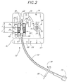
- Figure 2 is a top plan view of the catheter anchoring system of Figure 1;
- Figure 3 is a top plan view of a retainer of the catheter anchoring system of Figure 2;
- Figure 4a is a front elevational view of the retainer of Figure 3;
- Figure 4b is a rear elevational view of the retainer of Figure 3;
- Figure 5 is a side elevational view of the retainer of Figure 3;
- Figure 6 is a top plan view of a catheter anchoring system in accordance with another preferred embodiment of the present invention;
- Figure 7a is a front elevational view of a retainer and rail assembly of the catheter anchoring system of Figure 6;
- Figure 7b is a side elevational view of the retainer and rail assembly of Figure 6;
- Figure 8 is a cross-sectional view of the retainer and rail assembly taken along line 8-8 of Figure 7a;
- Figure 9 is a top plan view of a catheter anchoring system in accordance with an additional preferred embodiment of the present invention;
- Figure 10 is a side elevational view of an S-clip of the catheter anchoring system of Figure 9 taken along line 10-10;
- Figure 11 is a top perspective view of a catheter anchoring system in accordance with an additional preferred embodiment of the present invention;
- Figure 12 is a top plan view of the catheter anchoring system of Figure 11 illustrating an adaptor held by a retainer;
- Figure 13a is a side elevational view of the retainer of Figure 12;
- Figure 13b is a top plan view of the retainer of Figure 12;
- Figure 14 is a partially sectioned perspective view of an alternative embodiment of a catheter adaptor which may be used with the anchoring system of Figure 11;
- Figure 15a is side elevational view of a catheterization system in accordance with another preferred embodiment of the present invention with a retainer of the catheterization system shown in cross-section;
- Figure 15b is a top plan view of the retainer of Figure 15a as viewed in the direction of
arrows 15b-15b; - Figure 15c is a front end elevational view of the retainer of Figure 15a as viewed in the direction of
arrows 15c-15c; and - Figure 16 is a perspective view of a catheterization system configured in accordance with another embodiment of the present invention, and illustrates a catheter in a position separate from a retainer of the catheterization system;
- Figure 17 is a perspective view of a catheterization system configured in accordance with another embodiment of the present invention, and illustrates the a catheter adaptor having a plurality of radial recesses and a retainer having a plurality of projections that cooperate with the recesses when the retainer receives the catheter adaptor; and
- Figure 18 is a perspective view of the catheterization system configured in accordance with an additional embodiment of the present invention, and illustrates the catheter adaptor having a plurality of radial recesses and a retainer having a plurality of projections that extend into a channel having a tapered diameter.
-
- Figure 1 illustrates in perspective view a
catheter anchoring system 10 in accordance with the present invention. The anchoringsystem 10 securely connects a tube 12 (e.g., a fluid supply tube) to anindwelling catheter 14 and maintains thecatheter 14 in the desired indwelling position. The anchoringsystem 10 is designed for rapid attachment to thecatheter 14 and to the patient, without requiring precise alignment or positioning of the components of theanchoring system 10. - Moreover, sturdy anchoring of the catheterization system is achieved without the use of surgical tape. For most catheterization, the anchoring system is attached to the patient only once. Although the
fluid supply tubing 12 may be replaced every 24 to 48 hours for intravenous catheterization, the components of theanchoring system 10 attached to the patient remains in place. Thus, surgical tape need not be applied and removed from the patient's skin on multiple occasions. - The
catheter anchoring system 10 principally comprises aflexible pad 16 having an adhesivebottom side 18 which attaches to the skin of a patient when used. Thepad 16 supports aretainer 20. Theretainer 20 is configured to receive and secure in place acatheter adaptor 22 which interconnects thehub 30 of anindwelling catheter 14 and thefluid supply tube 12 connected to a fluid supply container (not shown). The container maintains the fluid to be dispensed to the patient which is fed either by gravity or by pressure. A clamp (not shown) may be used to regulate the fluid flow through thetubing 12. Thepad 16 may also support atubing clip 24 which is used to retain a portion oftubing 12. - Although Figure 1 illustrates the catheter anchoring system located on the back of a patient's hand (illustrated in phantom lines), it is contemplated that the present invention may be used for catheterization in other locations on the patient's body. For instance, the anchoring system may be used on the medial side of the wrist in connection with a radial artery. The anchoring
system 10 may also be used for epidural catheterization, as discussed in detail below, and thus located on the anterior or posterior of the patient's torso. - Figure 1 illustrates a longitudinal axis, a transverse axis and a lateral axis in relation to the
catheter anchoring system 10 to facilitate the following description. Additionally, as used herein, "the longitudinal direction" refers to a direction substantially parallel to the longitudinal axis. "The lateral direction" and "the transverse direction" are in reference to the lateral axis and transverse axis, respectively. Also, "proximal" and "distal" are in reference to the proximity of the fluid supply container attached to the tube 12 (see Figure 1). The individual components of thecatheter anchoring system 10 will now be described in detail. - Figure 1 illustrates the
catheter adaptor 22 interconnected with acatheter 14. Figure 2 illustrates thecatheter adaptor 22 disconnected fromcatheter 14. Although these figures illustrate theadaptor 22 as the type disclosed in U.S. Patent No. 5,193,273, it is contemplated that other types of adaptors can be used as well with the presentcatheter anchoring system 10. For instance, thecatheter adaptor 22 could be a lure-type adaptor, such as the type illustrated by Figure 11 and described below, or a lure-locktype catheter adaptor 22, such as the type illustrated by Figure 14 and described below. It is contemplated that those skilled in the art could readily select the type ofcatheter adaptor 22 to be used with the presentcatheter anchoring system 10 depending on the particular application (e.g., venous, arterial, epidural, peripheral, etc.) of theanchoring system 10. - As best seen in Figure 2, the
adaptor 22 comprises atubular body 25 defined between a distal end 26 and aproximal end 28. Theproximal end 28 is adapted to receive a distal end of thetube 12. In an exemplary embodiment, at least a portion the fluid supply tube is permanently attached to the bodyproximal end 28. As shown in Figure 2, the proximal end of the tubing may then include a standard lure-type connector 29 to connect into afluid supply line 12. - The distal end 26 is configured to engage the
proximal hub 30 of the catheter 14 (see Figure 1) or any lure-type connector. Although Figure 2 illustrates the distal end of theadaptor 22 as having a frusto-conical shape configured to engage a standard lure-type catheter hub 30, it is contemplated that the distal end 26 could be configured as well to engage other types of catheter connectors, such as, for example, a Toughy-Bourst adaptor. - A
support arm 32 extends outwardly from thetubular body 25 in cantilever fashion. Thesupport arm 32 supports, on a radially outer end of thearm 32, a clip support element (not shown) that extends generally parallel to and is spaced from a longitudinal axis of thetubular body 25. - Figure 2 further illustrates a
clip 34 of the catheter adaptor. Theclip 34 attaches to and slides over the clip support element in the longitudinal direction. Theclip 34 includes adistal latch 36 which has a generally forked shape to engage a outer surface of thecatheter hub 30 distal of a hub collar 38 (see Figure 1) to securely attach theadaptor 22 to thecatheter hub 30. - Interengaging structure (not shown) between the clip support element and the
clip 34 permits theclip 34 to slide in the proximal direction, but prevents theclip 34 from sliding in the distal direction. The interengaging element desirably comprises a series of ratchet teeth (not shown) disposed up on upper surface of the clip support element and a pawl (not shown) connected to theclip 34. The pawl extends from theclip 34 in a cantilever fashion and engages the ratchet teeth to prevent distal movement of the clip, as discussed in detail in U.S. Patent No. 5,193,273. - The
tubular body 25, thesupport arm 32 and the clip support element are preferably integrally formed of molded plastic, such as, for example, a clear polycarbonate, so as to be generally stiff, but somewhat flexible. Thesupport arm 32 desirably has enough elasticity to bend. Depressing the proximal end of theclip 34 towards thetubular body 25 moves thelatch 36 of theclip 34 away from thetubular body 25. In this manner, theclip 34 pivots about thetubular body 25. - With reference again to Figure 2, the clip support element desirably comprises a
protuberance 40 positioned on aninner surface 42 of the clip support element, proximate to the proximal end of theclip 34. The protuberance is spaced from the support arm by a distance L. Theprotuberance 40 prevents theclip 34 from pivoting when secured by theretainer 20, as discussed below in detail. Theprotuberance 40 also limits the degree of deflection of thesupport arm 32 to reduce fatigue, as fully explained in U.S. Patent No. 5,193,273. - Figures 3 through 5 illustrate the
retainer 20. Theretainer 20 has a generally parallelepiped shape defining acentral channel 44 interposed between a pair of opposinglongitudinal walls 46. Thecentral channel 44 extends through theretainer 20 along an axis which is generally parallel to the longitudinal axis of the retainer. - As best seen in Figure 4, the
central channel 44 has a generally circular cross-sectional shape which is truncated at a upper end to form a generally U-shaped channel having anupper opening 47. Thecentral channel 44 has a diameter sized to receive thetubular body 25 of thecatheter adaptor 22. In a preferred embodiment, the diameter of thecentral channel 44 generally matches that of thetubular body 25 or is slightly larger. - In cross-section, the
central channel 44 extends through an arc greater than 180 degrees about the channel axis such that the transverse length of theopening 47 is less than the diameter of thecentral channel 44. In an exemplary embodiment, thecentral channel 44 extends through an arc of about 200 degrees about the channel axis. - Figure 5 illustrates the channel axis which is desirably skewed relative to a
base surface 48 of theretainer 20. An incident angle formed between thebase surface 48 and the channel axis is less than 45 degrees. The incident angle desirably ranges between 0 degrees and 30 degrees. In an exemplary embodiment for intravenous use, the angle preferably equals approximately 7 degrees. In another exemplary embodiment for arterial use, the incident angle preferably equals about 22 degrees. In a further exemplary embodiment, for peripherally inserted central catheters (PICC), the incident angle preferably equals 0 degrees. - The
longitudinal walls 46 are substantially identical. Eachwall 46 has a thickness measured in the lateral direction less than the length of thesupport arm 32. Thewall 46 is thus interposed between thetubular body 25 and theclip 34 when thetubular body 25 is inserted into thecentral channel 44. The length of eachwall 46, measured in the longitudinal direction, is preferably coextensive with the length of theretainer 20. - Each
wall 46 comprises a uniform series ofslots 50. The series comprises at least two (2)slots 50, and not more than twenty (20)slots 50. More preferably, the series comprises less than seven (7)slots 50. In an exemplary embodiment, as illustrated in the figures of the application, the series comprises four (4)slots 50. - Each
slot 50 is sized to receive thesupport arm 32 of thecatheter adaptor 22 to prevent longitudinal displacement of theadaptor 22, as discussed in detail below. Eachslot 50 desirably has a rectangular shape. As seen in Figure 3, theslots 50 extend from anexterior surface 52 through thewall 44, and open into thecentral channel 44. The width of each slot 50 (measured longitudinally) is desirably slightly greater than the width of thesupport arm 32, measured in the longitudinal direction to receive thesupport arm 32, as discussed below. - As illustrated by Figure 5, each
slot 50 has a height as measured in the transverse direction between anupper edge 54 of thelongitudinal wall 46 and the bottom 56 of thecentral channel 44. The height of theslot 50 desirably equals approximately the width of thesupport arm 32 such that thesupport arm 32 does not protrude from theretainer 20 in the transverse direction. - The spacing S between the
slots 50, on center, desirably equals about half the distance L (see Figure 2) between thesupport arm 32 and theprotuberance 40 of thecatheter adaptor 22. - As Figure 3 illustrates, a distance X between the most
distal slot 50 and the distal end of theretainer 20 is less than the longitudinal distance Y (see Figure 2) between thesupport arm 32 and thelatch 36 positioned in its most proximal position. This spacing enables thesupport arm 32 to rest in the mostdistal slot 50 with thelatch 36 retaining acatheter hub 30 distal of the retainer distal end. - Figure 5 illustrates the
upper edge 50 of thelongitudinal wall 46 which comprises a series of chamfers 58, each of which slopes into aslot 50. That is, the portion ofupper edge 50 of thelongitudinal wall 46 which surrounds aslot 50 includes a pair of chamfers 58, with one chamfer 58 located on either side of theslot 50. The chamfers 58 slope downward toward theslot 50 to facilitate the insertion of thesupport arm 32 of thecatheter adaptor 22 into theslot 50, as discussed below. - As shown by Figures 3 and 5, each
longitudinal wall 46 further comprises arelief 60 disposed on the proximal end of theretainer 20. Therelief 60 is sized to receive theprotuberance 40 of theadaptor 22. The depth of therelief 60 measured in the lateral direction desirably is slightly greater than the height of the protuberance 40 (i.e., the distance by which the protuberance protrudes from the inner surface 42). - The
relief 60 is spaced in the longitudinal direction from the mostproximal slot 50 by a distance approximately equal to the spacing S between theslots 50. Thus, theprotuberance 40 rests in therelief 60 with thesupport arm 32 positioned in either of the two mostproximal slots 50, as discussed in detail below. - Figures 3 and 4 illustrate a key-
way groove 62 of theretainer 20. The key-way groove 62 facilitates the removal of thecatheter adaptor 22 from theretainer 20, as discussed below in detail. The key-way groove 62 lies at the proximal end of theretainer 20. The key-way groove 62 extends into theretainer 20, and toward theretainer base surface 48 from thebottom surface 56 of thecentral channel 44. The key-way groove 62 has a transverse width less than the diameter of thecentral channel 44, and more preferably has a width approximately equal to two-thirds the diameter of thecentral channel 44. The longitudinal length of the key-way groove 62 desirably equals approximately the longitudinal length of therecesses 60 in thelongitudinal walls 46. - The
retainer 20 is made of relatively stiff plastic material (e.g., polycarbonate), but is somewhat flexible such that theadaptor 22 forces theupper edges 54 of thelongitudinal walls 46 outwardly when a nurse presses theadaptor 24 into thecentral channel 44 of theretainer 20. When theadaptor 22 sits in thecentral channel 44, theupper edges 54 of thewalls 46 snap inwardly to their original position to securely hold theadaptor 22 within theretainer 20. - An adhesive attaches the
retainer 20 tobase pad 16. Alternatively, theretainer 20 may be attached to thebase pad 16 by like means (e.g., embedding or otherwise weaving theretainer 20 into the base pad 16) as well. - As illustrated by Figure 1, the
flexible base pad 16 comprises a laminate structure comprising an upper paper or other woven ornon-woven cloth layer 64, an innercellulose foam layer 66, and thebottom adhesive layer 18. Alternative, theflexible base pad 16 may comprise an adhesive bottom layer and an upper cellulose foam layer. An upper surface of the foam layer is roughened by corona treating the foam with a low electric charge, as known in the art. The roughened or porous upper surface of thebase pad 16 improves cyano-acrylate (or other types of adhesive) adhesion when attaching theretainer 20 to thepad 16. - A removable paper or plastic backing (not shown) desirably covers the
bottom adhesive layer 18 before use. The backing preferably resists tearing and is divided into a plurality of pieces to ease attachment of thepad 16 to the patient's skin, as explained below. Desirably, the backing is split along the center line of theflexible base pad 16 in order to expose only half of theadhesive bottom surface 18 at one time. The backing also advantageously extends beyond at least one edge of thebase pad 16 to ease removal of the backing from theadhesive layer 18. - As seen in Figure 2, one or
more tabs 67 may be attached to a portion of the backing which extends beyond theflexible base pad 16. In an exemplary embodiment, thetabs 67 have the same laminate structure as theflexible base pad 16. Thetabs 67 also can be formed by the paper backing extending beyond the edge of thebase pad 16. Thetab 67 may also includeindicia 69 in the form of dots, words, figures or the like to indicate the placement of fingers when removing the backing from thebase pad 16. - A nurse grips the
tab 67, preferably at the location of theindicia 69, and peels the backing off one half of thebottom adhesive layer 18. The nurse then places thebottom layer 18 against the patient's skin to adhere thebase pad 16 to the patient. Light pressure over theupper layer 64 assures good adhesion between thebase pad 16 and the patient's skin. Thebase pad 16, due to its flexibility, conforms to the contours of the topical surface to which thebase pad 16 adheres. The nurse then repeats this procedure for the other half of thepad 16. Alternatively, the nurse may completely remove the backing from thepad 16 before attaching thepad 16 to the patient's skin. - The
base pad 16 desirably comprises anotch 68 positioned distal of the location of theretainer 20 on thepad 16 and adjacent to the point of insertion of the catheter cannula. Thenotch 68 is sized to permit visual inspection of the catheterized site. - As seen in Figure 2, the
base pad 16 desirably may compriseindicia 70 in the form of an arrow which indicates the proper orientation of thebase pad 16 in reference to catheterized site. Although the figures illustrate the indicia in the form of an arrow, it is contemplated that other forms of indicia, such as, for example, words or other graphics, could be used as well. In proper use, as illustrated in Figure 1, theindicia 70 should point in the proximal direction, towards the indwellingcatheter 14, or otherwise indicate the proper locate of thepad 16 in reference to theindwelling catheter 14. - In an exemplary embodiment, the laminate structure of the base pad is preferably formed by rolling a paper tape, such as a micro-porous rayon tape, available commercially as MICRO-PORE tape from 3M (Item No. 1530), over a medical grade polyvinyl chloride foam tape, such as that available commercially from 3M (Item No. 9777L). The foam tape preferably includes the bottom liner or backing. The
base pad 16 and thetabs 67 are then stamped out of the laminated sheet of foam and paper. The backing between the tabs and the base pad, however, is desirably not severed such that thetabs 67 remain attached to the backing covering theadhesive section 18 of thebase pad 16. The backing is then cut into two pieces along the center line of thepad 16 and between thetabs 67. - Figures 1 and 2 illustrate the
tube clip 24. Theclip 24 secures thefluid supply tube 12 to form a safety loop, as known in the art. - The tube clip has a plate-
like base 72 adhered to or embedded in thebase pad 16. Thetube clip 24 may be located on thebase pad 16 on either side of theretainer 20 to accommodate left hand or right hand mounting. As illustrated in Figure 6, the anchoringsystem 10 may further include asecond tube clip 24 located on the other side of theretainer 20 from thefirst tube clip 24. - The
clip 24 defines achannel 74 having a generally circular cross-sectional configuration truncated to form anupper orifice 76. The diameter of thechannel 74 is desirably slightly less than that of thefluid supply tube 12 so as to ensure a secure interconnection. Thechannel 74 receives a portion of thefluid supply tube 12 through theorifice 76 upon application of gentle pressure or by pulling thetubing 12 across and through theorifice 76 of thetube clip 24, as explained below. Theclip 24 surrounds a substantial portion of thetubing 12 with thetubing 12 positioned within thechannel 74. - As seen in Figure 2, the upper edge of the channel includes tapered ends 77 at the proximal and distal ends of the
clip 24. Each tapered end 77 forms a smooth transition between the side edge of thechannel 74 and the upper edge, and tapers in lateral width from the side edge toward the center of thetube clip 24. The tapered ends 77 help guide thefluid supply tube 12 into thechannel 74 when a nurse pulls the tube across theclip 24. Thus, the nurse does not have to pinch thetube 12 to insert it into theclip 24. Also, the nurse's gloves do not get stuck in theclip 24 when inserting thetube 12, as is typically the case where the nurse is required to pinch thetube 12 to insert it into theclip 24. - As illustrated in Figures 1 and 2, the
catheter anchoring system 10 desirably additionally includes aslide clamp 78 to regulating fluid flow through the tubing, as known in the art. Theclamp 78, at one end, includes anaperture 80 which receives thefluid supply tube 12, and, at the opposite end, includes atab 82. Theclamp 78 has a generally forked shape formed by a pair ofprongs 84 which defines theaperture 80. Thetube 12 snaps between theprongs 84 and into theaperture 80, which has a diameter slightly larger that thefluid supply tube 12. - The
prongs 84 converge together in the direction towards thetab 82 to form atapering slot 86 which opens into theaperture 80. Theprongs 84 pinch thetube 12 closed with thetube 12 positioned in theslot 86 so as to block fluid flow therethrough. Theclamp 78, however, slides over thetube 12 with thetube 12 positioned through theaperture 80. - The
tab 82 desirably has a rectangular shape which generally corresponds the to shape of the key-way groove 62 of theretainer 20. Thetab 82 preferably has a thickness greater than that of the distal end of key-way groove 62, measured in the transverse direction, so as to pry theadaptor 22 from theretainer 20. As explained in detail below, thetab 82 may be used to remove thecatheter adaptor 22 from theretainer 20. - Figure 6 through 8 illustrate a catheter anchoring system 10a in accordance with another preferred embodiment of the present invention. Where appropriate, like numbers with an "a" suffix have been used to indicate like parts of the two embodiments for ease of understanding.
- The catheter anchoring system 10a is substantially identical to the above-described
anchoring system 10, with the addition of a retainerlocation adjustment mechanism 90. - As best seen in Figure 8, the
location adjustment mechanism 90 comprises abase 92 and interlocking mechanism 94 which interconnects thebase 92 and theretainer 20a. Theretainer 20a slides over thebase 92 and the interlocking mechanism 94 secures theretainer 20a to the base 92 at various longitudinal positions. The adjustment mechanism thus allows for precise positioning of theretainer 20 relative to thecatheter 14 after thepad 16 is attached to the patient's skin. - The
base 92 has a generally parallelepiped shape and comprises arail 96. Figure 7a best illustrates that therail 96 desirably has a "dove-tail" configuration in cross section. That is, therail 96 has a cross-sectional shape with a flatupper edge 98 and a pair of opposing side edges 100, eachedge 100 being angled inward from theupper edge 98 toward the middle of therail 96. Therail 96 extends along the longitudinal length of the base 92 from thedistal end 102 of the base 92 to a point just short of the baseproximal end 104. Thebase 92 includes a pair ofstops 106 at theproximal end 104 which close off the proximal end of therail 96. - An adhesive attaches the base 92 to base pad 16a. Alternatively, the
base 92 may be attached to the base pad 16a by like means (e.g., embedding or otherwise weaving the base 92 into the base pad 16a) as well. - The
retainer 20a, configured in accordance with the above-description, additionally comprises agroove 108 having a cross-sectional shape corresponding to that of therail 96. Theretainer groove 108 receives thebase rail 96 in a manner permitting theretainer 20a to slide over thebase 92, but preventing theretainer 20a from moving in the transverse direction away from thebase 92. The base stops 106 also limit the retainer's longitudinal travel in a proximal direction. - The interlocking mechanism 94 comprises a plurality of
teeth 110 disposed on anupper surface 112 of thebase 92, and apawl 114 connected to theretainer 20a. Theteeth 110 desirably have generally rectangular cross-sectional shapes, and lie in seriatim along the longitudinal axis of thebase 92. The upper edge of eachtooth 110 includes achamfer 112 to facilitate the engagement of thepawl 114 with a hollow 116 formed betweenadjacent teeth 110, as discussed below. The longitudinal length of eachtooth 110 desirably extends generally normal to the longitudinal axis of thebase 92. - The
pawl 114 has a shape configured to insert into and engage with the hollow 116 defined between theteeth 110. Thepawl 114 preferably has a width, measured in the longitudinal direction, slightly less than that of the hollow 116. - The
retainer 20a comprises an aperture 118 extending between the retainer base surface 48a and thechannel bottom surface 56a. Aflexible finger 120 extends from theretainer 20a in a cantilever fashion and into the retainer aperture 118. Theflexible finger 120 supports thepawl 114 at its distal end. Although Figure 8 illustrates thefinger 120 as extending in the distal direction, it is contemplated that thefinger 120 can alternatively extend in the proximal direction as well. - The
flexible finger 120 preferably comprises aprotuberance 122 which extends upwardly beyond thechannel bottom surface 56a and into the central channel 44a with thefinger 120 in an undeflected state. The cantilever nature of thefinger 120 enables thefinger 120 to deflect downward so that theprotuberance 122 lies below theretainer bottom surface 56a. With thefinger 120 so deflected, thepawl 114 engages the series ofteeth 110. That is, thepawl 114 inserts into a hollow 116 defined between theteeth 110. The interengagement betweenpawl 114 and theteeth 110 prevents theretainer 20a from sliding over thebase 92. - Figures 9 and 10 illustrate a catheter anchoring system 10b in accordance with a further embodiment of the present invention. Where appropriate, like numbers with an "b" suffix have been used to indicate like parts of the embodiments for ease of understanding.
- The catheter anchoring system 10b is substantially identical to the
anchoring system 10 first described above, with the addition of an S-clip 124 to retain a microbore orsmall bore tubing 126. The microbore tubing is commonly used, for example, with epidural catheterization procedures, as discussed in detail below. - The S-
clip 124 comprises a generallyU-shaped channel 128 defined by a pair of arcuate,upstanding walls 130 extending from abase plate 132. As best seen in Figure 10, the S-clip 124 further comprises a plurality ofretainers 134, eachretainer 134 having aspherical head 136 support by acylindrical stem 138. The stems 138 extend from thebase plate 132. The retainer stems 138 are positioned from one another and from theupstanding walls 130 by a distance slightly greater than the diameter of themicrobore tubing 126. Theretainers 134 are also positioned such that thespherical heads 136 of theretainers 134 are positioned from one another and from theupstanding walls 130 by a distance slightly less than themicrobore tubing 126. As best seen in Figure 10, the retainer heads 136 prevent themicrobore tubing 126 from disengaging from the S-clip 124 in the transverse direction once themicrobore tubing 126 is snaked between theretainers 134 and theupstanding walls 130. - An adhesive attaches the
base plate 132 of the S-clip 124 tobase pad 16b. Alternatively, thebase plate 132 may be attached to thebase pad 16b by like means (e.g., embedding or otherwise weaving thebase plate 132 into thebase pad 16b) as well. - The components of the
anchoring system 10, save the base pad 16 (i.e., theretainer 20,tube clip 24,adaptor 22,slide clamp 78,base 92 and S-clip 124), may be constructed in any of a variety of ways which will be well known to one of skill in the art. For instance, each individual component may be integrally molded such as by injection molding or by thermoplasty. The components preferably comprise a durably, flexible material, and more preferably comprise a generally inert, non-toxic material. In a preferred embodiment, the components are molded of plastic, such as, for example, polycarbonate, polyvinylchloride, polypropylene, polyurethane, tetrafluoroethylene (e.g., TEFLON ), polytetrafluoroethylene (a.k.a., PTEF), acetal resin (e.g., DELRIN ), chlorotrifluoroethylene (e.g., KEL-F ), nylon or like polymers. - The following discussion of the method of use will be with reference to Figures 1 and 2, and initially will be in the context of intravenous catheterization. As the following discussion will illustrate, however, it is understood that the
anchoring system 10 can be used in other catheterization procedures as well. The discussion of the method of use is intended to augment the above description of the invention, and, thus, should be read together. - A nurse typically begins the catheterization process by positioning the
catheter 14 at a desired location above a vein. The nurse introduces a needle or other stylus through a cannula portion of thecatheter 14 and into the skin of the patient at a desired angle of incident. For intravenous use, thecatheter 14 commonly has an incident angle of approximately 7. The nurse then inserts the cannula of thecatheter 14 into the patient and withdraws the needle or stylus. Thecatheter hub 30 remains exposed above the skin. - The nurse inserts the distal end of the adaptor 26 into the
catheter hub 30. Theclip 34 has been slidably mounted in a most distal position so that it does not interfere with the insertion of the adaptor distal end 26 into thecatheter hub 30. - The nurse then slides the
clip 34 in a proximal direction to engage thecatheter hub 30. In this manually selected position, theclip 34 securely attaches theadaptor 22 to thecatheter 14. The rachet teeth of theadaptor 22 cooperate with the pawl to resist distal movement of theclip 34 and to hold theclip 34 in the manually selected position. - The nurse removes the paper backing which initially covers the
adhesive bottom surface 18 of thebase pad 16, and attaches thepad 16 to the patient's skin proximate to theindwelling catheter 14. Specifically, the nurse grips thebacking tab 67 proximate to theretainer 20. Theindicia 69 on thetab 67 indicates the locate at which the nurse should grip thetab 67. The nurse then pulls on thetab 67 and peels the backing off one half of thebottom adhesive layer 18. The nurse positions theslot 68 of thepad 16 around thecatheter cannula 14 with the instructing indicia 70 (e.g., indicating arrow) pointing in the direction of thecatheter 14. The nurse then places thebottom layer 18 against the patient's skin to adhere thebase pad 16 to the patient. Light pressure over theupper layer 64 assures good adhesion between thebase pad 16 and the patient's skin. Thebase pad 16, due to its flexibility, conforms to the contours of the topical surface to which thebase pad 16 adheres. - The nurse then repeats this procedure for the other half of the
pad 16. Alternatively, the nurse may completely remove the backing from thepad 16 before attaching thepad 16 to the patient's skin. - The nurse orients the
adaptor 22 with theclip 34 positioned to the side of the tubular body 25 (i.e., with thesupport arm 32 extending in the lateral direction) and locates theadaptor support arm 32 above the series ofretainer slots 50 with thelatch 36 positioned distal of the retainer distal end. - The nurse then snaps the
adaptor 22 into theretainer 20 located proximal of thepad notch 68. In doing so, theadaptor 22 is pressed between thelongitudinal walls 46 of theretainer 20 with thesupport arm 32 extending in a lateral direction. As the nurse presses theadaptor 22 into theretainer 20, the chamfered edges 58 around theslots 50 of thelongitudinal wall 46 guide thesupport arm 32 into one of theslots 50. - As mentioned above, the
opening 47 of thechannel 46 has a smaller width measured in the lateral direction than the diameter of thetubular body 25. Thelateral walls 46 thus deflect outwardly in a lateral direction. Once thetubular body 25 of theadaptor 22 rests within thecentral channel 44 of theretainer 20, thelateral walls 46 spring back to snap theadaptor 22 in place. Thewalls 46 of theretainer 20 thus prevent unintentional transverse and lateral movement of theadaptor 22. - In this position, the
protuberance 40 of theadaptor 22 either rests either in aslot 50 or in therelief 60, proximal of theslot 50 through which thesupport arm 32 passes. Theprotuberance 40 engages a portion of thelongitudinal wall 46, which forms either therelief 60 or theslot 50, to prevent theclip 34 from pivoting relative to thetubular body 25. Theprotuberance 40 thus ensures that thelatch 36 maintains engagement with thecatheter hub 30. - The
slot 50 through which thesupport arm 32 passes prevents theadaptor 22 from sliding in the longitudinal direction. That is, theslot 50 prevents longitudinal displacement of theadaptor 22 when secured within thecentral channel 44. - The ergonomic design of the
retainer 20 provides for a variety of positions of theadaptor 22 in theretainer 20 so that theretainer 22 is not technique or position sensitive. That is, a nurse can simply press theadaptor 22 into theretainer 20, irrespective of the side on which thesupport arm 32 is located, and irrespective of the position of thesupport arm 32 relative to aparticular slot 50. So long as thesupport arm 32 is positioned above the series ofslots 50, the chamfered edges 58 of thewall 46 will guide thesupport arm 32 into aslot 50. Theprotuberance 40 of theadaptor 22 also fits within anadjacent slot 50 or therelief 60. - With the
support arm 32 extending through aslot 50 of theretainer 20, theadaptor 22 lies in a "low profile" position. That is, thesupport arm 32 of theadaptor 22 extends in the lateral direction to reduce the overall height of theanchoring system 10, as measured in the transverse direction. This position of theadaptor 22 reduces the risk of thesystem 10 interfering with surrounding action. Theretainer 20, however, allows theadaptor 22 to rotate either to a position in which thesupport arm 32 extends in the transverse direction, or to a position 180 degrees for the original position to locate theadaptor clip 34 on the opposite side of theretainer 20. - Once in the low profile position, the
adaptor 22 will normally remain in this position until theadaptor 22 and its associatedtubing 12 are removed and replaced by another. - As Figure 1 illustrates, the nurse may also form a safety loop in the
fluid supply tubing 12, as known in the art, and secure the safety loop to the patient by inserting a portion of thetubing 12 into thetube clip 24. The safety loop absorbs any tension applied to the fluid supply tube to prevent theadaptor 22 and/orcatheter 14 from being pulled. - A nurse may use the
slide clamp 78 to remove theadaptor body 25 from theretainer 20. The nurse inserts thetab 82 of theslide clamp 78 into the key-way groove 62 on the proximal end of theretainer 20. Because thetab 82 has a larger width than the depth of the key-way groove 62, measured in the transverse direction, thetab 62 pries thetubular body 25 from thecentral channel 44 as the nurse inserts thetab 82 into the key-way groove 62 in the distal direction. The nurse may further use theslide clamp 78 to leverage the proximal end of thetubular body 25 out theupper opening 47 of theretainer 20. Having displaced the proximal end of theadaptor 22 from theretainer 20, the nurse may easily remove the adaptor distal end from of theretainer 20. Alternatively, the nurse may also remove thetubular body 25 by lifting up on thetubing 12 while holding down thepad 16 or theretainer 20 with the other hand. - Figures 6 through 8 illustrate the catheter anchoring system 10a particularly suited for arterial catheterization. Because of the criticality of the incident angle (i.e., the angle at which the catheter 14a projects into the patient) at which the catheter 14a must be maintained, it is advantageous to precisely position the
retainer 20a so that theretainer 20a holds the catheter 14a at the desired incident angle. The desired range of incident angle commonly is about 5 -30 for arterial catheterization. The incident angle preferably ranges between about 15 and about 25, and more preferably equals about 22. - A nurse inserts the catheter cannula 14a into an artery in a similar manner to that described above in connection with intravenous catheterization. The nurse subsequently connects the adaptor 22a to the indwelling catheter 14a as previously described. The nurse also attaches the flexible pad 16a to the patient in a like manner to that described above. If desired, the nurse can remove one of the
wings 140 of the pad 16a before attaching the pad 16a to the patient, by tearing the pad 16a along theperforation line 142. - The nurse orients the adaptor 22a with the clip 34a positioned to the side of the tubular body 25a (i.e., with the support arm 32a extending in the lateral direction) and locates the adaptor support arm 32a above the series of
retainer slots 50a with the latch 36a positioned distal of the retainer distal end. If the nurse positions pad 16a too close to or too far from the indwelling catheter 14a, the nurse can slide theretainer 20a in the desired direction to locate theretainer slots 50a beneath the adaptor support arm 32a. - The nurse then snaps the adaptor 22a into the
retainer 20a located proximal of the pad notch 68a. In doing so, the chamferededges 58a around theslots 50a of the longitudinal wall 46a guide the support arm 32a into one of theslots 50a. Theretainer 20a automatically slides longitudinally to precisely position acorresponding slot 50a beneath the support arm 32a. The adaptor 22a thus snaps into theretainer 20a without causing the catheter 14a to move substantially. - The tubular body 25a contacts the
protuberance 122 of thefinger 120 and causes thefinger 120 to deflect downward as the adaptor tubular body 25a snaps into the central channel 44a. In turn, thepawl 114 engages the series ofteeth 110 which prevents longitudinal movement of theretainer 20a while holding theadaptor 20a. If the nurse removes the adaptor 22a -- preferably by using the slide clamp tab 82a -- thefinger 120 springs back to its undeflected state and theretainer 20a freely slides over therail 96. Thepawl 114 normally does not engage the series ofteeth 110. - The ability to precisely position the
retainer 20a beneath the catheter adaptor 22a connected to the catheter 14a, enables the nurse to hold the catheter 14a in a stable position and ensures that theretainer 20a will hold the adaptor 22a, and thus the catheter 14a, at the precise incident angle. Without the ability to adjust the longitudinal position of theretainer 20a, the nurse may perform a series of position iterations before properly locating base pad 16a, and thus theretainer 20a, relative to the indwelling catheter 14a. - For epidural catheterization, an anesthesiologist, for example, inserts the distal end of
microbore tubing 126 into the epidural space. The proximal end of themicrobore tubing 126 conventionally includes a Toughy-Bourst adaptor 144 or other adaptor device to couple with thefluid supply tube 12b transporting the anesthesia. It is imperative that the connection between themicrobore tubing 126 and thefluid supply tubing 144 remain intact, and that the distal end of themicrobore tubing 126 remains in place. For if the epidural space is exposed to air-borne microbes, meningitis may develop. Thus, a secure interconnection between themicrobore tubing 126 and thefluid supply 12b should exist, and themicrobore tubing 126 should be isolated from any tension placed on either thefluid supply tube 12b, as well as theadaptor 22b. - Figures 9 and 10 illustrate the catheter anchoring system 10b particularly suited for epidural catheterization. A doctor uses the present anchoring system 10b in a manner similar to that described above in connection with intravenous catheterization, with the exceptions that doctor connects the
adaptor 22b tomicrobore tubing 126 and adheres thebase pad 16b to the patient's torso. - The doctor subsequently snakes the
microbore tubing 126 through the S-clip 124 by first pressing thetubing 126 between aretainer 134 and thewall 130, and then wrapping thetubing 126 between the first andsecond retainers 134. Light pressure forces thetube 126 between theretainers 134. The doctor then wraps thetube 126 back between thesecond retainer 134 and thesecond wall 130, and presses thetube 126 therebetween. The S-clip 124 secures themicrobore tube 126 in place and isolates themicrobore tube 126 from tension placed on theadaptor 22b and/or thefluid supply tube 12b with themicrobore tube 126 inserted accordingly. - As mentioned above, it is contemplated that other types of adaptors in addition to the one disclosed above can be used as well with the present catheter anchoring system. Figures 11 and 12 illustrate a catheter anchoring system 10c in accordance with a further embodiment of the present invention which includes a different catheter adaptor style. Where appropriate, like numbers with a "c" suffix have been used to indicate like parts of the embodiments for ease of understanding.
- Like the catheter anchoring systems described above, the present catheter anchoring system 10c principally comprises a
flexible anchor pad 16c having an adhesivebottom side 18c, which attaches to the skin of the patient. Thepad 16c supports aretainer 20c. Theretainer 20c is configured to receive and secure in place acatheter adaptor 22c which connects to an indwelling catheter 14c. The pad 16a may also support atube clip 24c which is used to retain a portion of thetubing 12c. - Figure 11 illustrates the
adaptor 22c as comprising a generallytubular body 25c defined between adistal end 26c and aproximal end 28c. Theproximal end 28c is adapted to receive a distal end of thetube 12c. In an exemplary embodiment, at least a portion of thefluid supply tube 12c is permanently attached to the bodyproximal end 28c. - The
distal end 26c is configured to engage a proximal end of the indwelling catheter 14c (not shown). Although Figures 11 and 12 illustrate thedistal end 26c of theadaptor 22c as having a frusto-conical shape configured to engage a standard lure-type catheter hub 30c (not shown), it is contemplated that thedistal end 26c could be configured as well to engage other types of connectors. - Figure 14 illustrates an alternative configuration of the
distal end 26d of thecatheter adaptor 22d. Again, for consistency, like numbers with a "d" suffix have been used to indicate like parts of the catheter adaptor of Figure 11 and the catheter adaptor of Figure 14. - The
catheter adaptor 22d includes a standard lure-lock type fitting 220 attached to the body 25d of thecatheter adaptor 22d so as to circumscribe thedistal end 26d of thecatheter adaptor 22d. The lure-lock fitting 220 preferably is attached in a manner which permits the fitting 220 to be rotated about the catheter adaptor body 25d. It is contemplated, however, that the distal end of the adaptor could comprise a female lure-lock type connector (i.e., a hub including nubs or threads on its external surface) as well if required by a particular application. - In the illustrated embodiment, the fitting 220 has a generally tubular shape with a closed
proximal end 222. Theclosed end 222 includes anaperture 224 of a sufficient size to receive a portion of the adaptor body 25d, as described below. The fitting 220 includes conventionalinternal threads 226 in order to engage corresponding threads of a conventional female lure-lock fitting (not shown). - The adaptor body 25d desirably includes an
annular groove 228 which receives a portion of theclosed end 222 of the fitting 220 to interconnect the fitting 220 and the adaptor body 25d. This interconnection also permits the fitting 220 to be rotated about the adaptor body 25d. - To assemble the
catheter adaptor 22d, the conical shapeddistal end 26d of the body 25d is inserted into theaperture 224 of fittingclosed end 222. The body 25d is then forced into the fitting 220 to slightly deflect theclosed end 222 until theclosed end 222 snaps into theannular groove 228 of the body 25d. In this position, the body 25d captures a portion of the fitting 220 to couple these elements together. - With reference to Figure 11, the
adaptor 22c includes at least oneannular collar 200 interposed between the proximal anddistal ends tubular body 25c. Theadaptor 22d of Figure 14 also includes a likeannular collar 200d. It is contemplated that thecollar 200 of theadaptor 22c of Figure 11 and thecollar 200d of theadaptor 22d of Figure 14 will be substantially identical, and, thus, the description herein will be understood as applying equally to both embodiments. - The
annular collar 200 flares radially outwardly and circumscribes thetubular body 25c. Theannular collar 200 has a thickness measured in a longitudinal direction which is slightly less than a width of aslot 50c in aretainer wall 46c so that thecollar 200 fits within theslot 50c of aretainer wall 46c, as discussed in detail below. - The
adaptor 22c is preferably formed of a durable, biocompatible plastic material. Theadaptor 22c more preferably is formed of clear plastic so a nurse can see bubbles or backflow through theadaptor 22c. In an exemplary embodiment, the adaptor is formed of polycarbonate by injection molded; however, those skilled in the art will readily appreciate that the adaptor can be formed by other construction methods known in the art. - Figures 11 and 12 also illustrate the
retainer 20c which is substantially identical to theretainer 20 described above. Theretainer 20c comprises acentral channel 44c interposed between a pair of opposinglongitudinal walls 46c. Thecentral channel 44c extends through theretainer 20c along an axis which is generally parallel to a longitudinal axis of theretainer 20c. - The
central channel axis 44c has a generally circular cross-sectional shape which is truncated at an upper end to form anopening 47c. Thecentral body 44c has a diameter sized to receive thetubular body 25c of thecatheter adaptor 22c. In a preferred embodiment, the diameter of thecentral channel 44c generally matches that of thetubular body 25c. - In cross section, the
central channel 44c extends through an arc greater than 180 degrees about the channel axis such that the lateral length of theopening 47c is less than the diameter of thecentral channel 44c. In an exemplary embodiment, the cross-sectional shape of thecentral channel 44c extends through an arc of about 200 degrees about the channel axis. - As best seen in Figure 13a, the channel axis is desirably skewed relative to a
base surface 48c of theretainer 20c. An incident angle formed between thebase surface 48c and the channel axis is less than 45 degrees. The incident angle desirably ranges between 5 degrees and 30 degrees. In an exemplary embodiment for intravenous use, the angle preferably approximately equals 7 degrees. - The
longitudinal walls 46c are substantially identical. Eachwall 46c has a thickness measured in the lateral direction less than the length of thesupport arm 32 of theadaptor 22, as it is desirable for thepresent retainer 20c to accept both the above-describedadaptor 22 which comprises asupport arm 32 connected to aclip 34, as well as thepresent adaptor 22c which comprises anannular collar 200. Preferably, the thickness of thewall 46c measured in the lateral direction is greater than the distance measured radially by which thecollar 200 extends beyond the exterior surface of thetubular body 25c (i.e., a radial height). The length of eachwall 46c, as measured in the longitudinal direction, is preferably coextensive with the length of theretainer 20c. - Each
wall 46c comprises a uniform series ofslot 50c. The series comprises at least two (2)slots 50c and not more than twenty (20)slots 50c. More preferably, the series comprises less than seven (7)slots 50c. In an exemplary embodiment, as illustrated in the figures, the series comprises four (4)slots 50c. - As discussed above, each
slot 50c is sized to receive thecollar 200 of theadaptor 22c, as well as thesupport arm 32 of thecatheter adaptor 22, to prevent longitudinal displacement of therespective adaptor slot 50c desirably has a rectangular shape. As seen in Figure 12, theslots 50c extend from anexterior surface 52c, through thewall 46c, and open into thecentral channel 44c. The width of theslot 50c, as measured in the longitudinal direction, is desirably slightly greater than the width of thesupport arm 32 and the width of thecollar 200. - As illustrated by Figure 13a, each
slot 50c extends in the transverse direction from anupper edge 54c of thelongitudinal wall 46c to a point below the bottom 56c of thecentral channel 44c. The height of theslot 50c, as measured in the transverse direction, is thus greater than the distance between theupper edge 54c and thechannel bottom 56c of theretainer 20c. As seen in Figure 13b, theretainer 20c further includes a series oflateral grooves 202 which extend between opposingslots 50c and extend into theretainer 20c from thechannel bottom surface 56c. The opposingslots 50c and groove 202 thus form a lateral channel which extends through theretainer 20c in the lateral direction and cuts into theretainer 20c from theupper edge 54c to a point below thechannel bottom surface 56c. Thegroove 202 desirably is sized to receive a portion of thecollar 200 such that with thetubular body 25c positioned within thecentral channel 44c, thecollar 200 extends between opposingslots 50c and into thegroove 202. Thus, thegroove 202 has a depth, measured between thelower surface 56c of thecentral channel 44c and the bottom of the groove in transverse direction, which is greater than the radial height of theannular collar 200. - Figure 13b illustrates that the spacing S between the
slots 50c, on center, desirably equals about half the distal L (see Figure 2) between thesupport arm 32 and theprotuberance 40 of thecatheter adaptor 22. The position of the slots in relation to the proximal anddistal ends retainer 20c is desirably configured in accordance with the spacing and positioning discussed above in connection with the above-describedretainer 22, such that thepresent retainer 22c can be used with the above-describedadaptor 22, including aclip 34. - Figures 11 and 13a illustrate the upper edge of each
longitudinal wall 46c which comprises a series ofchamfers 58c formed and positioned as disclosed above in connection with theretainer 20. As discussed above, thechamfers 58c slope downwardly towards theslot 50c to facilitate the insertion of either thesupport arm 32 of the above-describedcatheter adaptor 22 or theannular collar 200 of thepresent catheter adaptor 22c into theslot 50c. - As Figures 11-13b illustrate, each
longitudinal wall 46c may further comprise arelief 60c disposed on the proximal end of theretainer 20c. The configuration and position of therelief 60c desirably is in accordance with the above description of theretainer 20. Figure 11 further illustrates that theretainer 20c may additionally comprise a key-way groove 62c to facilitate removal of thecatheter adaptor 22c from theretainer 20c, as discussed above. The key-way groove 62c desirably is also positioned and configured in accordance with the above disclosure in connection with theretainer 20. - The
retainer 20c is made of relatively stiff plastic material, but is somewhat flexible such that theadaptor 22c forces theupper edges 54c of thelongitudinal walls 46c outwardly when a nurse presses theadaptor 22c into thecentral channel 44c of theretainer 20c. Theretainer 20c is desirably formed of polycarbonate by injection molding. When theadaptor 22c sits within thecentral channel 44c, theupper edges 54c of thewalls 46c snap inwardly to their original position to securely hold theadaptor 22c within theretainer 20c. - An adhesive preferably attaches the
retainer 20c to theanchor pad 16c. Alternatively, theretainer 20c may be attached to theanchor pad 16c by like means as well, e.g., embedding or otherwise weaving the retainer into theanchor pad 16c. - Figure 11 illustrates the
anchor pad 16c as comprising a flexible, laminate structure comprising an upper paper or other woven ornon-woven cloth layer 64c and abottom adhesive layer 18c, with an innercellulose foam layer 66c interposed therebetween. Alternatively, theflexible base pad 16 may comprise an adhesivebottom layer 18 and an upper cellulose foam layer. An upper surface of the foam layer is roughened by corona treating with a low electric charge, as known in the art. Thefoam layer 66c forms a cushion between the patient's skin and the rigid,plastic retainer 20c andtube clamp 24c. Theadhesive layer 18c may comprise a coating of diaphoretic or nondiaphoretic material, depending upon the patient's skin condition. A medical grade foam tape with a diaphoretic or a nondiaphoretic adhesive is available commercially from NDM Manufacturers. - The removable paper or plastic backing (not shown) desirably covers the
bottom adhesive layer 18 before use. As discussed above and illustrated in Figure 12, the backing is preferably divided into a plurality of piece and includestabs 67c to ease removal of the backing from thepad 16. Thetabs 67c may includeindicia 69c (e.g., dots, text, arrows, etc.) to indicate the location at which to grip the correspondingtab 67c when peeling the removable backing off thepad 16c. - As best seen in Figure 12, the
anchor pad 16 desirably has a generally trapezoidal shape with rounded corners. Adistal edge 206 of theanchor pad 16c desirably has a width, as measured in the lateral direction, wider than that of aproximal edge 204. The longerdistal edge 206 provides a longer adhesive surface over a rough contact surface, such as, for example, over knuckles, vertebrae, or the like. The generally trapezoidal shape, however, minimizes the overall size of theanchor pad 16c attached to the patient. The trapezoidal shape also provides the same surface area as a square pad with a appearance of a smaller pad. Thelongitudinal sides 208 of theanchor pad 16c preferably taper from theproximal edge 206 to thedistal edge 204, and more desirably have concave shapes. - The anchor pad includes a
notch 68c positioned along theproximal edge 204 of theanchor pad 16c and adjacent to the point of insertion of the catheter cannula. Preferably, thenotch 68c is symmetrically positioned about thechannel axis 44c of theretainer 20c attached to theanchor pad 16c. Thenotch 68c is sized to permit visual inspection of the catheterized site and is large enough to allow for variable placement of thepad 16c with respect to the insertion site. That is, thenotch 68c is large enough that a nurse is not required to precisely position the pad on the patient's skin with respect to the indwelling catheter 14c (not shown). - As seen in Figures 11 and 12, the
anchor pad 16c desirably may compriseindicia 70c sometimes in the form of an arrow which indicates the proper orientation of theanchor pad 16 in reference to the catheterized site. When properly used, theindicia 70c points toward the indwelling catheter 14c (not shown). - The
anchor pad 16c preferably supports aclip 24c which secures thefluid supply tube 12c to theanchor pad 16c. As seen in Figure 12, thefluid supply tube 12c is preferably looped back around in a proximal direction and inserted into theclip 24c to form a safety loop, as known in the art. Thetube clip 24c is desirably configured in accordance with the above description. Theclip 24c may be made in a variety of sizes to accommodate various calibers offluid flow tubing 12c. - In use, a nurse typically uses the catheter anchoring system 10c in connection with an indwelling catheter 14c (not shown). The catheter 14c is inserted into a body lumen, such as a vein, in accordance with the above description. The nurse then inserts the
distal end 26c of theadaptor 22c into a catheter hub 30c (not shown) to connect theadaptor 22c to the catheter 14c. The nurse may then secure theadapter 22c to the catheter 14c by means of the ratchet clip, or the lure-lock fitting. - The nurse removes the paper backing which initially covers the
adhesive bottom surface 18c of theanchor pad 16c, as described above, and attaches theanchor pad 16c to the patient's skin proximate to the indwelling catheter 14c. The nurse specifically positions thenotch 68c of thepad 16c around the catheter cannula 14c with the indicatingarrow 70c pointing in the direction of the catheter 14c. The nurse generally aligns theproximal edge 204 of theanchor pad 16c with the insertion site. - The nurse positions the
adaptor 22c above the series ofretainer slots 50c, and snaps theadaptor 22c into theretainer 20c. In doing so, theadaptor 22c is pressed between thelongitudinal walls 46c of theretainer 20c with theannular collar 200 extending into opposingslots 50c and into thecorresponding groove 202 of theretainer 20c. As the nurse presses the adaptor into theretainer 20c, the chamferededges 58c around theslots 50c of thelongitudinal walls 46c guide theannular collar 200 into theslots 50c. Theretainer 20c secures theadaptor 20c as described above. - With the
annular collar 200 positioned in the opposingslots 50c theadaptor 22c is prevented from sliding in a longitudinal direction. - Like the above-described embodiments of the retainer, the ergonomic design of the
retainer 20c provides for various positions of theadaptor 22c in theretainer 20c so that theretainer 22c is not technique- or position-sensitive. That is, a nurse can simply press theadaptor 22c into theretainer 20c, irrespective of the position of theannular collar 20 relative to aparticular slot 50c of theretainer 20c. So long as theannular collar 200 is positioned above the series ofslots 50c, the chamferededges 58c of thewall 46c will guide theannular collar 200 into theslot 50c. - The present embodiment of the
retainer 20c, as mentioned above, may also be used with the above-describedadaptor 22 having theclip 34. A nurse uses the present retainer with the above-describedadaptor 22 in the same manner as described above in connection with the above-describedretainer 20. - If the catheter hub 30 (see Figure 1) is a standard female lure-lock fitting, the lure-lock fitting 220 (Figure 14) of the
adaptor body 22d is rotated with thedistal end 26d inserted into thecatheter hub 30 to interlock the correspondingfittings catheter adaptor 22d is then used with the anchoring system in a like manner to that described above. - The above embodiments illustrate the adaptor with the radially extending member being affixed to an end of a tube set or other fluid line. The radially extending member can also be arranged on the adaptor or fitting that is affixed to the proximal end of the catheter body. Figures 15a through 15c illustrate this arrangement.
- Figures 15a through 15c illustrate a catheterization system configured in accordance with another embodiment of the present invention. The catheterization system includes a catheter and an anchoring system that includes a retainer and an anchoring pad. Although the anchoring pad has been omitted from Figures 15a through 15c to simplify the drawings, the anchor pad desirably is constructed in accordance with the above description and is shaped in the form shown in Figure 16. Again, for consistency, like numbers with an "e" suffix have been used to indicate like parts of the anchoring system of Figures 11 and of 15a-15c. The above description of like components thus should be understood as applying equally to the present embodiment, unless stated otherwise.
- The catheter desirably includes an elongated tubular body with a tubular adaptor or fitting attached to the body. At least one lumen of the adaptor communicates with a corresponding lumen of the catheter. In the illustrated embodiment, the
adaptor 22e is permanently attached to a proximal end of the fitting and is configured to cooperate with a corresponding adaptor formed on a distal end of a fluid line. Theadaptor 22e, however, can be releasably attached to the catheter body. - In the illustrated embodiment, the
tubular adaptor 22e is configured as a female-component of the coupling between the catheter body and the fluid line. Theadaptor 22e of course can be configured as the male component of the coupling. In either case, both the male and female adaptors of the coupling have corresponding generally frusto-conical shapes which mate together in a generally fluid tight engagement. The coupling adaptors also include interengaging elements that lock together the adaptors. Thetubular adaptor 22e of the illustrated embodiment includes a threadedcoupler 306 formed by an external thread that runs about aproximal end 300 of a tubular body of theadaptor 22e. The external thread of the threaded coupler is configured to corresponding to an internal thread of a spin nut disposed on the end of the corresponding adaptor (such as the type illustrated in Figure 14). - In the illustrated embodiment, the tubular body of the
adaptor 22e includes a frusto-conicalshaped section 304 on thedistal side 302 of the threadedcoupler 306. The corresponding form of theadaptor 22e generally corresponds to a conventional catheter hub, such as the type illustrated in Figure 1. - Unlike a conventional catheter hub, however, the
adaptor 22e includes a radially extending member that projects from the tubular body. In the illustrated embodiment, the radially extending member comprises anannular collar 200e that circumscribes a portion of the frusto-conicalshaped section 304 of the tubular body. Thecollar 200e is generally positioned about midway between the proximal anddistal ends - As understood from Figures 15a through 15c, the
retainer 20e defines acentral channel 44e that has a generally conical shape corresponding to the shape of the adaptor tubular body. Thechannel 44e is interposed between a pair of opposing converginglongitudinal walls 46e. - The
walls 46e are spaced apart such that there is a variable lateral distance therebetween. Thewalls 46e have aproximal end 300 and adistal end 302, with the proximal end width being desirably wider than the distal end width. - The
central channel 44e extends through theretainer 20e along the longitudinal axis and between the convergingwalls 46e. Thechannel 44e is similarly of variable lateral dimension as taken at points along the longitudinal axis direction. - The
central channel 44e has a truncated upper section which gives the channel a generally U-shape having anupper opening 47e. The bottom and side surfaces of thechannel 44e are arcuate and substantially match the shape of thecatheter adaptor 22e, which can be received therein. The variable diameter of thechannel 44e is sized to receive the longitudinal length of thecatheter adaptor 22e. Each section of thechannel 44e has arcuate shape of a radius of curvature that generally matches a corresponding section of thecatheter adaptor 22e. In the illustrated embodiment, the radii of curvature vary along the longitudinal length of thechannel 44e; however, thechannel 44e can have generally uniform radii of curvature, as illustrated by the above embodiments. - In cross section, as best understood from Figure 15c, the
channel 44e extends through an arc of greater than 180 degrees about the longitudinal axis such that the lateral length of theupper opening 47e is less than the diameter of thechannel 44e at a given point in the longitudinal direction. In the illustrated embodiment, thechannel 44e desirably extends through an arc of about 200 degrees about the channel axis. - The retainer also includes at least one
slot 50e that lies generally perpendicular to the longitudinal axis and extends across thechannel 44e to section thechannel 44e into a proximal channel portion and a distal channel portion. In the illustrated embodiment, the proximal and distal channel portions have generally equal longitudinal lengths; however, they need not have the same length. The length of the channel portions though desirably provides stability to thecatheter adaptor 22e when inserted into theretainer 20e to prevent thecatheter adaptor 22e from yawing (i.e. pivoting relative to the retainer within a plane parallel to the anchor pad). Each channel section of theretainer 20e is also sized to receive a corresponding section of thecatheter adaptor 22e. Eachslot 50e is sized to receive thecollar 200e of thecatheter adaptor 22e. - The
slot 50e has a thickness that substantially matches the thickness of theadaptor collar 200e. The thickness ofslot 50e, however, is less than the combined longitudinal lengths of the proximal and distal channel portions. This dimensional relationship provides further stability to the retainedcatheter adaptor 22e when inserted into theretainer 20e. - In the illustrated embodiment, the
retainer 20e includes at least twolateral slots 50e arranged in series (i.e., next to each other) between the proximal and distal channel portions. The series of slots desirably includes between two (2) and twenty (20) slots. More preferably, the series comprises less than seven (7) slots. The illustrated embodiment shows two (2) slots. - As described above, each
slot 50e is sized to receive a portion of the adaptorannular collar 200e to prevent longitudinal displacement of the catheter, as discussed in detail above. Eachslot 50e desirably has a rectangular shape and extends from an exterior surfaces 52e through thewalls 46e, and across thecentral channel 46e. The width of eachslot 50e (measured longitudinally) is desirably slightly greater than the width of the fitting 304, measured in the longitudinal direction to receive the fitting 304, as discussed above. - The
retainer 20e also desirably includes a relief 308 formed on the bottom of thechannel 44e. The relief 308 is sized to receive a portion of thecollar 200e when placed within one of theslots 50e. - Finger platforms 310 extend from the
side walls 46e of theretainer 20e. The finger platforms 310 are sized and configured to enable allow a health care provider to press theretainer 20e against the skin of the patient while pulling up on thecatheter adaptor 22e or on the adaptor to which it is connected, when disengaging thecatheter adaptor 22e from theretainer 20e. - So configured, in addition to the interengagement between the
slots 50e andannular collar 200e, longitudinal movement of the catheter in the proximal-to-distal direction is further inhibited by cooperation between the conical-shapedchannel 44e and frusto-conicalshaped fitting 304. That is, when an applied force directs the fitting 304 in the distal direction, the fitting 304 advances until contact with a section of thewalls 46e (which are of uniformly narrower diameter as measured toward the proximal end of thewalls 46e). When contact is made, the fitting 304, and catheter which is attached thereto, is restricted from further distal movement. - Figure 16 illustrates another embodiment of the catheterization system similar to that described above in connection with Figures 15a-15c. Accordingly, like reference numerals with a "f" suffix have been used to indicate similar components between these embodiments. The above description of like components thus applies equally to the present embodiment, unless stated otherwise.
- In the illustrated embodiment, the conical shaped section of the
catheter hub 304 has an irregular step in diameter between the side proximal 300f of thecollar 200f and the side distal 302f of thecollar 200f. That is a minimum diameter of the conical section on the side proximal 300f thecollar 200f is larger than a maximum diameter of the conical section on the side distal 302f of thecollar 200f. - The retainer 20f has a shape corresponding to that of the conical section of the
catheter adaptor 22f. The proximal 300f channel portion has a radius of curvature generally matching that of the proximal 300f side of the adaptor conical section. And the distal 302f channel portion has a radius of curvature generally matching that of the distal 302f side of the adaptor conical section. As such, a minimum diameter of the proximal 300f channel section is larger than a maximum diameter of the distal 302f channel section. - The retainer 20f is mounted atop an anchor pad 16f with its upper opening 47f being exposed and facing away from the anchor pad 16f. The construction of the anchor pad 16f and the retainer 20f, as well as the attachment of the retainer 20f to the anchor pad 16f, are in accordance with the above description. The anchor pad 16f also supports a
tube clip 24f, as illustrated in Figure 16. - As similar to the above embodiment, the present catheterization system is used by first connecting the catheter to a fluid line (be it supply or drainage). The catheter is inserted into a body lumen, such as a vein, in accordance with the above description. The nurse then inserts a distal end of one of the
coupling adaptor 22c into a catheter adaptor to connect together the adaptors. The nurse may then interconnect the adapters by means of the above-described ratchet clip, or the lure-lock fitting formed between the threaded coupler on the proximal end of the catheter adaptor and the spin nut on the end of the adaptor attached to the fluid tube. - The nurse removes the paper backing which initially covers an adhesive bottom surface of the anchor pad 16f, as described above, and attaches the anchor pad 16f to the patient's skin proximate to the indwelling catheter. The nurse specifically positions a notch of the pad 16f around the catheter body or cannula. The nurse generally aligns the proximal edge of the anchor pad 16f with the insertion site.
- The nurse positions the
adaptor 22f above the series of retainer slots 50f, and snaps theadaptor 22f into the retainer 20f. In doing so, the adaptor 20f is pressed between thelongitudinal walls 46f of the retainer 20f with theannular collar 200f extending into one of the slots 50f of the retainer 20f. As the nurse presses theadaptor 22f into the retainer 20f, chamferededges 312 around the slots 50f (see Figure 15a) of thelongitudinal walls 46f guide theannular collar 200f into the slots 50f. With theannular collar 200f positioned in one of the slots 50f, theadaptor 22f is prevented from sliding in a longitudinal direction. - Like the above-described embodiments of the retainer 20f, the ergonomic design of the retainer 20f provides for various positions of the
adaptor 22f in the retainer 20f so that the retainer 20f is not technique- or position-sensitive. That is, a nurse can simply press theadaptor 22f into the retainer 20f, irrespective of the position of theannular collar 200f relative to a particular slot 50f of the retainer 20f. So long as theannular collar 200f is positioned above the series of slots 50f, the chamferededges 312 of the wall will guide theannular collar 200f into the slot 50f. - Figures 17 and 18 illustrate a catheterization system configured in accordance with another embodiment of the present invention. Like the other embodiments of the catheterization system, this embodiment includes a catheter and an anchoring system that includes a retainer and an anchoring pad. Again, for consistency, like numbers with an "g" suffix have been used to indicate like parts of the anchoring system of Figures 11 and of 16. The above description of like components thus should be understood as applying equally to this embodiment, unless stated otherwise.
- The present embodiment, like the previous embodiments, utilizes the concept of providing an adaptor and retainer which cooperate with each other to secure the catheter to the body of a patient and inhibit movement of the catheter in the longitudinal, transverse and lateral directions. Also, like the previous embodiments, the anchoring system can include the concept of not being position or technique sensitive. That is, the medical attendant can simply locate the catheter adaptor generally above the retainer and press the adaptor into the retainer. Engagement thus requires only coarse alignment of the adaptor with the retainer.
- Figure 17 shows the
retainer 20g comprising a longitudinal channel 44g formed between a pair of substantiallyparallel walls 46g and configured to receive the tubular body of theadaptor 22g in a snap fit manner. The construction of the channel thus is similar to that described above and about a longitudinal axis L. - The
retainer 20g additionally comprises at least one projection orprotuberance 400 that extends from one of thewalls 46g toward the longitudinal axis in the lateral direction. Theprojection 400 is sized and configured to cooperate with a recess on thecatheter adaptor 22g, as explained below. Theprojection 400, however, can extend into the channel 44g toward the longitudinal axis in the transverse direction. - In the illustrated embodiment, the
retainer 20g includes a plurality ofprojections 400. In one mode, two projections are positioned across from each other onopposite walls 46g. The set ofprojections 400 thus oppose each other. Theretainer 20g also desirably includes a plurality of projection sets 400 which are spaced along a length of the channel 44g. The multiple projection sets 400 thus provide multiple positions in which theadaptor 22g can occupy within theretainer 20g, so as to require only coarse alignment between theretainer 20g and theadaptor 22g before engagement. Both laterally and transversely extendingprojections 400 can be used with the retainer. - The
projections 400 desirably are positioned between a first portion of the channel 44g and a second portion of the channel 44g. In the illustrated embodiment, one channel portion is formed at a proximal end of the channel 44g and the other end is formed at a distal end of the channel 44g. Each of the channel portions desirably are sufficiently long and support a sufficient length of theadaptor 22g so as to prevent theadaptor 22g from rocking. - Each
projection 400 desirably has sufficient thickness or bulk so as to resist nominal applied forces, i.e. not break when the medical attendant presses on it. Also, the portion of theprojection 400 that projects into the channel 44g is of sufficient lateral or transverse dimension to inhibit movement of thecatheter adaptor 22g in the longitudinal direction, without inhibiting placement of thecatheter adaptor 22g into or out of the channel 44g. That is, theprojections 400 extend into the channel by a sufficient amount to engage with corresponding structure on thecatheter adaptor 22g, as described below. - In the illustrated embodiment, each
projection 400 has generally a rectangular shape in a plane generally parallel to theretainer base 48g. Thus, theprojections 400 generally form a series of square teeth along a section of eachwall 46g at an upper rim of the channel 44g. Theprojection 400, however, can be configured in a wide variety of other shapes, including, but not limited to, semi-circular, square, curvilinear, triangular or the like. Thus, theprojection 400 may be linear, as illustrated, or curved or curvilinear to suit a particular application, so as to inhibit migration of thecatheter adaptor 22g in the longitudinal direction. - Below the upper rim of the channel 44g, each projection tapers back toward the
corresponding side wall 46g. In the illustrated embodiment, thistaper 406 generally follows an arcuate path that desirably corresponds to a surface to theadaptor 22g, as described below. Theprojections 400, however, can extend about the entire arc of the channel 44g (i.e., down one side wall, across the bottom of the channel and up the other side wall) or theprojections 400 can extend downward to the channel bottom (Figure 18). - As noted above, the
projections 400 are advantageously sized and configured to cooperate with a corresponding recess(es) on thecatheter adaptor 22g. Without limitation, thecatheter adaptor 22g can be a fitting on the end of either the fluid tube, as shown in Figure 17, or the catheter as shown in Figure 18 (e.g., a catheter hub). - In one mode, the
projections 400 fit into the recess(es) and engage the sides of the recess(es) so as to inhibit longitudinal movement of theadaptor 22g relative to theretainer 20g. In the illustrated embodiment, theadaptor 22g includes a plurality of annular grooves or depressions 408 (e.g., three grooves); however, any number ofannular grooves 408 can be used with theadaptor 22g. In order to accommodate theadaptor 22g in multiple positions within theretainer 20g, however, the number of projection sets 400 should be less than the number ofgrooves 408. - Each
annular groove 408 is interposed between the proximal and distal ends 28g, 26g of theadaptor 22g and extends radially inward while circumscribing theadaptor 22g. Eachannular groove 408 also has a thickness measured in the longitudinal direction which is slightly less than the longitudinal length of theprojection 400 so that at least a portion of theannular depression 408 fits around theprojection 408 of theretainer wall 46g, as described above. - Each
annular groove 408 thus defines an arcuate surface on the exterior of theadaptor 22g. In the illustrated embodiment, the radius of this arcuate surface desirably is not greater than the radius of curvature followed by the corresponding projection(s) 400 as it tapers toward therespective wall 46g, as noted above. - Figure 18 is generally similar to Figure 17 except that the
retainer 20g is configured to receive a frusto-conicalshaped section 304g of theadaptor 22g, rather than anadaptor 22g having a uniform diameter, as shown in Figure 17. To form the snap fit engagement between theretainer 20g and taperedadaptor 22g, the channel 44g extends through theretainer 20g along the longitudinal axis and between convergingwalls 46g, thus forming a tapered or stepped region. The illustrated embodiment also shows fourprojections 400 formed on theretainer 20g, however, it is understood that any suitable number of projections (2-20) can be used with theretainer 20g. - The present embodiment of the catheterization system is used by first catheter is inserted into a body lumen, such as a vein, in accordance with the above description. The medical attendant then connects the catheter adaptors together so as to attach the catheter to the fluid line. The medical attendant may then interconnect the adapters by means of the above-described ratchet clip, or the lure-lock fitting formed between the threaded coupler on the proximal end of the catheter adaptor and the spin nut on the end of the adaptor attached to the fluid tube.
- The medical attendant positions the
adaptor 22g above the series ofretainer projections 400, and snaps theadaptor 22g into theretainer 20g. In doing so, theadaptor 22g is pressed between thelongitudinal walls 46g of theretainer 20g with at least a portion of theannular depression 408 receiving acorresponding projection 400. With at least a portion of theannular depression 408 positioned around one of theprojections 400, theadaptor 22g is inhibited from moving in a longitudinal direction. The medical attendant then removes the paper backing which initially covers an adhesive bottom surface of theanchor pad 16g and attaches theanchor pad 16g to the patient's skin proximate to the indwelling catheter, as described above. - As previously explained, the ergonomic design of the
retainer 20g provides for various positions of theadaptor 22g in theretainer 20g so that theretainer 20g is not technique or position sensitive. That is, a medical attendant can simply press theadaptor 22g into theretainer 20g, irrespective of the position of theannular depression 408 relative to aparticular projection 400 of theretainer 20g. Further, so long as theannular depression 408 is positioned above the series ofprojections 400, the chamfered edges 312g of thewall 46g will guide the annular depression around at least a portion of theprojection 400. - Although this invention has been described in terms of certain preferred embodiments, other embodiments apparent to those of ordinary skill in the art are also within the scope of this invention. It is also understood that various aspects of one embodiment can be interchanged with other embodiments. Accordingly, the scope of the invention is intended to be defined only by the claims which follow.
Claims (15)
- A catheterization system comprising:a catheter adaptor including at least one recess; anda retainer including,
a channel that extends through at least a portion of the retainer about a longitudinal axis, the channel configured such that at least a portion of the channel has a truncated cross-sectional shape with an opening along the longitudinal axis through which the catheter adapter can pass into the channel, and
at least one projection that projects into the channel in a direction generally normal to the longitudinal axis, the projection having a longitudinal length so dimensioned to substantially equal the longitudinal length of the recess of the adaptor so as to arrest longitudinal movement of the adaptor relative to the retainer. - A catheterization system as in Claim 1, wherein the channel includes a first channel portion and a second channel portion configured such that the channel portions have truncated cross-sectional shapes with openings along the longitudinal axis.
- A catheterization system as in Claim 1, wherein the at least one projection extends inwardly of the adjacent surfaces of at least a portion of the channel portion towards the longitudinal axis, and wherein the recess of the catheter adaptor extends radially inward and circumscribes at least a portion of the catheter adaptor.
- A catheterization system as in Claim 2, wherein the at least one projection has a longitudinal length that is less than the combined longitudinal lengths of the first and second channel portions.
- A catheterization system as in Claim 2, wherein at least one of the first and second channel portions has a longitudinal length greater than the longitudinal length of the projection, and wherein the at least one projection is positioned between the first and second channel portions.
- A catheterization system as in Claim 2, wherein each of the first and second channel portions has a generally arcuate shape of a radius of curvature generally matching that of a corresponding portion of the catheter adaptor received by the respective channel portion.
- A catheterization system as in Claim 1 or 2, wherein the channel portion is sized to surround at least a portion of the catheter adaptor through an arc of greater than 180° about the longitudinal axis so as to hold the catheter adaptor away from the skin of a patient.
- A catheterization system as in Claim 1 or 2, wherein the opening has a lateral width less than a diameter of the channel portion so as to receive the catheter adaptor in a generally snap-fit manner.
- A catheterization system as in Claim 1 or 2, wherein at least a portion of the channel has a truncated cross-sectional shape.
- A catheterization system as in Claim 1 or 2, wherein the cross-sectional shape of at least a portion of the channel tapers along its length, and wherein the catheter adaptor includes a tapering shaped section.
- A catheterization system as in Claim 1 or 2, additionally comprising a flexible anchor pad having an adhesive bottom surface and a top surface on which the retainer is mounted.
- A catheterization system as in Claim 1 or 2, wherein the channel includes first and second walls and a bottom wall, wherein the first and second walls converge in a direction towards the bottom wall, and wherein the at least one projection has a rectangular shape in a plane generally parallel to the bottom wall.
- A catheterization system as in Claim 1 or 2, wherein the channel includes first and second walls and a bottom wall, wherein the first and second walls converge in a direction towards the bottom wall, and wherein at least a portion of the projection extends in a direction that is generally parallel to the bottom wall.
- A catheterization system as in Claim 1 or 2, wherein the channel includes first and second walls and a bottom wall, wherein the first and second walls converge in a direction towards the bottom wall, and wherein at least a portion of the projection extends in a direction that is generally normal to the bottom wall.
- A catheterization system as in Claim 1 or 2, wherein the retainer comprises a plurality of projections positioned to oppose each other from opposite sides of the channel so as to form a projection set, and wherein the catheter adaptor comprises additional recesses, the additional recesses being located at different longitudinal positions along the length of the catheter adaptor, and wherein the plurality of projections are dimensioned to fit within any of the recesses so as to provide multiple positions in the longitudinal direction in which to insert said catheter adaptor into the retainer to prevent the catheter from moving in a longitudinal direction.
Applications Claiming Priority (5)
| Application Number | Priority Date | Filing Date | Title |
|---|---|---|---|
| US09/069,029 US6290676B1 (en) | 1989-07-24 | 1998-04-27 | Catheter anchoring system |
| US69029 | 1998-04-27 | ||
| US165367 | 1998-10-02 | ||
| US09/165,367 US6837875B1 (en) | 1993-03-19 | 1998-10-02 | Catheter anchoring system |
| EP99921487A EP1075299B1 (en) | 1998-04-27 | 1999-04-27 | Catheter anchoring system |
Related Parent Applications (1)
| Application Number | Title | Priority Date | Filing Date |
|---|---|---|---|
| EP99921487A Division EP1075299B1 (en) | 1998-04-27 | 1999-04-27 | Catheter anchoring system |
Publications (2)
| Publication Number | Publication Date |
|---|---|
| EP1475122A2 true EP1475122A2 (en) | 2004-11-10 |
| EP1475122A3 EP1475122A3 (en) | 2005-03-30 |
Family
ID=26749613
Family Applications (2)
| Application Number | Title | Priority Date | Filing Date |
|---|---|---|---|
| EP99921487A Expired - Lifetime EP1075299B1 (en) | 1998-04-27 | 1999-04-27 | Catheter anchoring system |
| EP04077158A Withdrawn EP1475122A3 (en) | 1998-04-27 | 1999-04-27 | Catheter anchoring system |
Family Applications Before (1)
| Application Number | Title | Priority Date | Filing Date |
|---|---|---|---|
| EP99921487A Expired - Lifetime EP1075299B1 (en) | 1998-04-27 | 1999-04-27 | Catheter anchoring system |
Country Status (8)
| Country | Link |
|---|---|
| US (1) | US6837875B1 (en) |
| EP (2) | EP1075299B1 (en) |
| KR (1) | KR100527007B1 (en) |
| AT (1) | ATE273726T1 (en) |
| AU (2) | AU3868799A (en) |
| CA (1) | CA2329785C (en) |
| DE (1) | DE69919532T2 (en) |
| WO (1) | WO1999055409A1 (en) |
Families Citing this family (80)
| Publication number | Priority date | Publication date | Assignee | Title |
|---|---|---|---|---|
| US6827705B2 (en) * | 1993-03-19 | 2004-12-07 | Venetec International, Inc. | Catheter anchoring system |
| US6572588B1 (en) | 2000-03-10 | 2003-06-03 | Venetec International, Inc. | Medical anchoring system |
| US6428515B1 (en) * | 2000-06-01 | 2002-08-06 | Venetec International, Inc. | Anchoring system for leur lock connector |
| US6551273B1 (en) | 2000-08-23 | 2003-04-22 | Scimed Life Systems, Inc. | Catheter having a shaft keeper |
| DE10055281B4 (en) * | 2000-11-08 | 2004-12-23 | Fresenius Kabi Deutschland Gmbh | Adapter for a PEG probe |
| EP1499380A2 (en) | 2002-05-01 | 2005-01-26 | Venetec International, Inc. | Medical line securement device |
| NZ538214A (en) * | 2002-08-15 | 2006-05-26 | Venetec Int Inc | Catheter securement device |
| US20060084922A1 (en) * | 2002-09-04 | 2006-04-20 | Ruark Botha | Device for securing a blood vessel cannula to a body |
| US7931658B2 (en) | 2002-09-20 | 2011-04-26 | Interrad Medical, Inc. | Temporary retention device |
| US8480629B2 (en) | 2005-01-28 | 2013-07-09 | Boston Scientific Scimed, Inc. | Universal utility board for use with medical devices and methods of use |
| US9248258B2 (en) * | 2005-03-16 | 2016-02-02 | Carefusion 303, Inc. | Method and apparatus for securing I.V. needle and luer fitting |
| US8197447B2 (en) * | 2005-04-19 | 2012-06-12 | Venetec International, Inc. | Flexible IV site protector |
| US8057440B2 (en) * | 2005-05-26 | 2011-11-15 | Venectec International, Inc. | Anchoring system for use with neonates |
| US8152035B2 (en) * | 2005-07-12 | 2012-04-10 | Thoratec Corporation | Restraining device for a percutaneous lead assembly |
| US7988673B2 (en) | 2005-07-14 | 2011-08-02 | Venetec International, Inc. | Protective dressing and methods of use thereof |
| CA2619979A1 (en) | 2005-08-31 | 2007-03-08 | Venetec International, Inc. | Anchoring system for a catheter |
| CA2653651C (en) | 2005-09-19 | 2014-03-25 | Venetec International Inc. | Medical tubing securement assembly and methods of use |
| US7879013B2 (en) | 2005-12-21 | 2011-02-01 | Venetec International, Inc. | Intravenous catheter anchoring device |
| US8052648B2 (en) | 2005-12-21 | 2011-11-08 | Venetec International, Inc. | Intravenous catheter anchoring device |
| US9138560B2 (en) | 2006-01-12 | 2015-09-22 | Venetec International, Inc. | Universal catheter securement device |
| EP1988945B1 (en) | 2006-01-12 | 2021-08-18 | Venetec International, Inc. | Universal catheter securement device |
| US8016794B2 (en) | 2006-03-09 | 2011-09-13 | Interrad Medical, Inc. | Anchor device and method |
| US7806873B2 (en) * | 2006-07-13 | 2010-10-05 | Venetec International, Inc. | Intravenous securement device with adhesively interconnected anchoring component and permeable adhesive strip |
| US8500698B2 (en) * | 2006-09-08 | 2013-08-06 | Zefon International, Inc. | Catheter anchor |
| US20080200880A1 (en) * | 2007-02-15 | 2008-08-21 | Kurt Kyvik | Catheter anchor |
| US8834425B2 (en) * | 2007-07-16 | 2014-09-16 | C.R. Bard, Inc. | Securement system employing polymeric gel |
| US9993619B2 (en) | 2007-07-17 | 2018-06-12 | C. R. Bard, Inc. | Securement system for a medical article |
| US8323251B2 (en) * | 2008-01-14 | 2012-12-04 | Fenwal, Inc. | Phlebotomy needle assembly and frangible cover |
| EP2110149B1 (en) * | 2008-03-28 | 2017-05-03 | Fenwal, Inc. | Winged needle assembly and frangible cover |
| US8235948B2 (en) * | 2008-06-27 | 2012-08-07 | Interrad Medical, Inc. | System for anchoring medical devices |
| US9480821B2 (en) | 2008-06-30 | 2016-11-01 | Venetec International, Inc. | Anchoring system for a medical article |
| US8038653B2 (en) | 2008-07-16 | 2011-10-18 | Interrad Medical, Inc. | Anchor systems and methods |
| CA2737640C (en) | 2008-09-19 | 2017-10-31 | C.R. Bard, Inc. | Medical device securement system |
| US20100100049A1 (en) * | 2008-10-22 | 2010-04-22 | Godfrey Mark W | Securement device for vascular access system |
| US8328764B2 (en) | 2009-02-06 | 2012-12-11 | Interrad Medical, Inc. | System for anchoring medical devices |
| EP2403579A4 (en) | 2009-03-04 | 2012-08-01 | Bard Inc C R | Catheter securement device |
| CN102438682A (en) | 2009-05-15 | 2012-05-02 | Cr巴德公司 | Universal stabilization device |
| US8394067B2 (en) | 2009-05-21 | 2013-03-12 | C.R. Bard, Inc. | Medical device securement system |
| US8323249B2 (en) | 2009-08-14 | 2012-12-04 | The Regents Of The University Of Michigan | Integrated vascular delivery system |
| US8740852B2 (en) | 2009-08-25 | 2014-06-03 | C. R. Bard, Inc. | Medical article securement device |
| WO2011044293A1 (en) | 2009-10-06 | 2011-04-14 | Venetec International, Inc. | Stabilizing device having a snap clamp |
| WO2011044259A1 (en) | 2009-10-06 | 2011-04-14 | Venetec International, Inc. | Stabilizing device having a locking collet |
| US20110098669A1 (en) * | 2009-10-26 | 2011-04-28 | Boyes George R | Intravenous spike holder for easier penetration of sealed intravenous bag |
| US10537714B2 (en) | 2009-11-11 | 2020-01-21 | Venetec International, Inc. | Stabilizing device for an extension set |
| WO2011109542A1 (en) | 2010-03-03 | 2011-09-09 | Venetec International , Inc. | Medical article with rotable wings |
| WO2011146781A1 (en) * | 2010-05-19 | 2011-11-24 | Tangent Medical Technologies Llc | Catheter stabilization device |
| US8814833B2 (en) | 2010-05-19 | 2014-08-26 | Tangent Medical Technologies Llc | Safety needle system operable with a medical device |
| WO2011146769A2 (en) | 2010-05-19 | 2011-11-24 | Tangent Medical Technologies Llc | Integrated vascular delivery system |
| CA2807045A1 (en) | 2010-07-30 | 2012-02-02 | Venetec International, Inc. | Securement device |
| TW201225997A (en) | 2010-08-20 | 2012-07-01 | Thoratec Corp | Assembly and method for stabilizing a percutaneous cable |
| US9962524B2 (en) | 2011-03-11 | 2018-05-08 | Venetec International, Inc. | Medical article securement device |
| WO2012145683A1 (en) | 2011-04-21 | 2012-10-26 | Venetec International, Inc. | Anchoring system |
| US8556859B2 (en) | 2011-12-21 | 2013-10-15 | Securcath LLC | Securement device for medical fixtures |
| CN105050647B (en) | 2013-03-15 | 2019-11-12 | 维尼泰克国际股份有限公司 | Fixed equipment with whole bridge piece and dressing |
| AU2014264380A1 (en) * | 2013-05-05 | 2015-12-24 | Resqdevices Pty Ltd | An intravenous cannula retainer |
| US9248259B2 (en) | 2013-08-14 | 2016-02-02 | Tidi Securement Products, Llc | Double notched catheter securement assembly |
| EP3102258A4 (en) | 2014-02-04 | 2017-12-27 | ICU Medical, Inc. | Self-priming systems and methods |
| KR200474714Y1 (en) | 2014-03-10 | 2014-10-13 | (주)지온메드 | Medical tube fixing device |
| US10576251B2 (en) | 2014-03-13 | 2020-03-03 | TDI Products, LLC | Offset catheter securement device with removable retention member |
| USD864384S1 (en) | 2014-03-13 | 2019-10-22 | Tidi Products, Llc | Split-loop offset catheter securement device |
| US9358366B2 (en) | 2014-03-13 | 2016-06-07 | Tidi Securement Products, Llc | Offset catheter securement device |
| USD842986S1 (en) | 2014-09-05 | 2019-03-12 | Tidi Products, Llc | Narrow IV securement device |
| USD780914S1 (en) | 2014-09-05 | 2017-03-07 | Tidi Products, Llc | Catheter adhesive device |
| US10350388B2 (en) | 2014-09-05 | 2019-07-16 | Tidi Securement Products, Llc | Peripheral intravenous and arterial catheter securement device |
| KR101711725B1 (en) * | 2015-03-03 | 2017-03-02 | 이상철 | Disposable Syringe close fasteners |
| JP6885929B2 (en) | 2015-09-09 | 2021-06-16 | ベー.ブラウン メルスンゲン アクチェンゲゼルシャフト | Infusion systems, connectors for use with catheter devices, and related methods |
| USD834711S1 (en) | 2016-02-04 | 2018-11-27 | Tidi Products, Lcc | Catheter and connector securement device |
| USD789527S1 (en) | 2016-02-04 | 2017-06-13 | Tidi Products, Llc | Catheter and connector securement device |
| CN113876488B (en) | 2016-05-13 | 2022-09-13 | C·R·巴德股份有限公司 | Catheter securement device including guide nose |
| CN113082349B (en) | 2016-06-27 | 2023-07-28 | 武田药品工业株式会社 | Syringe stabilization device |
| USD816833S1 (en) | 2017-01-10 | 2018-05-01 | Tidi Products, Llc | Access needle securement device |
| US10857320B2 (en) * | 2017-09-11 | 2020-12-08 | Christopher Walters | Pre-cut adhesive strips for securing airway tubes |
| KR102142153B1 (en) * | 2018-05-24 | 2020-08-06 | 주식회사 이화메디텍 | Connector for assisting subcutaneous injection |
| CN109011104A (en) * | 2018-08-28 | 2018-12-18 | 南京市第医院 | Inserted type chest drainage conduit |
| JP2022529044A (en) | 2019-04-17 | 2022-06-16 | バード・アクセス・システムズ,インコーポレーテッド | Catheter fixation device with extended anchor pad and release liner fastening function |
| KR102247858B1 (en) * | 2019-10-02 | 2021-05-04 | 주식회사 이화메디텍 | connector for assisting subcutaneous injection |
| CA3183520A1 (en) * | 2020-06-30 | 2022-01-06 | Mark BRUNING | Chest drainage system securing apparatus |
| KR102322577B1 (en) * | 2021-08-11 | 2021-11-08 | 엔지오텍 주식회사 | Direct medication injection device |
| KR102597188B1 (en) * | 2021-08-20 | 2023-11-02 | 주식회사 파인메딕스 | Gastrostomy Tube Kit |
| US11850342B2 (en) | 2022-03-21 | 2023-12-26 | Fresenius Medical Care Holdings, Inc. | Securing connections to dialyzers |
Citations (2)
| Publication number | Priority date | Publication date | Assignee | Title |
|---|---|---|---|---|
| US4224937A (en) | 1979-01-19 | 1980-09-30 | Whitman Medical Corporation | Stabilizing fitting for an intravenous catheter |
| US5192273A (en) | 1989-07-24 | 1993-03-09 | Steven F. Bierman | Catheterization system |
Family Cites Families (105)
| Publication number | Priority date | Publication date | Assignee | Title |
|---|---|---|---|---|
| US2525398A (en) | 1948-02-02 | 1950-10-10 | Arthur L Collins | Hypodermic syringe holder and guide |
| US2533961A (en) | 1949-09-29 | 1950-12-12 | Wilfrid J Rousseau | Intravenous needle immobilizer |
| US3064648A (en) | 1958-04-16 | 1962-11-20 | Abbott Lab | Intravenous needle assembly |
| US3245567A (en) | 1962-08-27 | 1966-04-12 | Johnson & Johnson | Sterile container |
| US3167072A (en) | 1962-10-11 | 1965-01-26 | Stone Hester Ellen | Intravenous needle and flow tube stabilizing means |
| US3394954A (en) | 1966-05-06 | 1968-07-30 | Sarns Inc | Tube coupling for medical appliances |
| US3529597A (en) | 1968-04-19 | 1970-09-22 | George T Fuzak | Fingertip bandage |
| US3686896A (en) | 1969-09-29 | 1972-08-29 | Smiths Industries Ltd | End fittings for flexible drive cables |
| CA938850A (en) | 1970-07-24 | 1973-12-25 | W. Edwards Donald | Device for venipuncture |
| US3677250A (en) | 1971-02-11 | 1972-07-18 | Morton I Thomas | Tabbed anchoring tape means |
| US3766915A (en) | 1971-12-21 | 1973-10-23 | Illinois Tool Works | Plastic needle holder |
| DE2305896C3 (en) | 1973-02-07 | 1975-11-20 | C.H. Boehringer Sohn, 6507 Ingelheim | Indwelling venous catheter with an inner needle |
| US3973565A (en) | 1973-07-20 | 1976-08-10 | Everett Medical Products Limited | Winged cannula with skin securing means |
| US4020835A (en) | 1973-08-16 | 1977-05-03 | Boehringer Ingelheim Gmbh | Catheter placement assembly |
| US3856020A (en) | 1973-09-17 | 1974-12-24 | S Kovac | Trocar-catheter assembly |
| US3900026A (en) | 1973-11-19 | 1975-08-19 | William H Wagner | Device for holding and protecting intravenous injection needles |
| US3942228A (en) | 1974-07-19 | 1976-03-09 | Buckman Thomas P | Tubing clamp |
| US4037599A (en) | 1976-01-26 | 1977-07-26 | Raulerson James D | Continuous flow catheter device |
| CH596843A5 (en) | 1976-02-12 | 1978-03-31 | Intermedicat Gmbh | |
| US4059105A (en) | 1976-03-24 | 1977-11-22 | Omnimed, Inc. | Cannula securing device |
| USD243477S (en) | 1976-03-24 | 1977-02-22 | Omnimed, Inc. | Intravenous tube anchor |
| US4082094A (en) | 1976-09-13 | 1978-04-04 | Dailey Calvin L | Locking device for intravenous insert |
| US4133312A (en) | 1976-10-13 | 1979-01-09 | Cordis Dow Corp. | Connector for attachment of blood tubing to external arteriovenous shunts and fistulas |
| US4114618A (en) | 1976-12-15 | 1978-09-19 | Vargas Jorge J | Catheter assembly |
| US4142527A (en) | 1977-02-07 | 1979-03-06 | Garcia Nelson C | Endotracheal tube holder |
| US4316461A (en) | 1977-02-22 | 1982-02-23 | Marais Henri J | Intravenous vascular stabilizer |
| US4129128A (en) | 1977-02-23 | 1978-12-12 | Mcfarlane Richard H | Securing device for catheter placement assembly |
| US4116196A (en) | 1977-03-17 | 1978-09-26 | Survival Technology, Inc. | Additive adapter |
| US4123091A (en) | 1977-11-21 | 1978-10-31 | Renal Systems, Inc. | Tube connector |
| USD256162S (en) | 1978-04-06 | 1980-07-29 | Xomed, Inc. | Pad for anchoring an infusion needle and the tubing connected thereto to the skin of a patient |
| US4250880A (en) * | 1979-06-08 | 1981-02-17 | Whitman Medical Corporation | Stabilizing fitting for an intravenous catheter |
| US4397647A (en) | 1979-01-19 | 1983-08-09 | Whitman Medical Corporation | Catheter stabilization fitting having a snap-over cover |
| US4362156A (en) | 1979-04-18 | 1982-12-07 | Riverain Corporation | Intravenous infusion assembly |
| US4496348A (en) | 1979-11-29 | 1985-01-29 | Abbott Laboratories | Venipuncture device |
| US4324236A (en) | 1979-12-03 | 1982-04-13 | Whitman Medical Corp. | Fitting for use in performing a vascular puncture |
| DE2949865C2 (en) | 1979-12-12 | 1985-04-18 | B. Braun Melsungen Ag, 3508 Melsungen | Hose connection for medical devices |
| US4326519A (en) | 1980-02-21 | 1982-04-27 | Abbott Laboratories | Venipuncture device |
| GB2086466A (en) | 1980-10-08 | 1982-05-12 | Wallace Ltd H G | Security clamp for surgical device |
| US4392853A (en) | 1981-03-16 | 1983-07-12 | Rudolph Muto | Sterile assembly for protecting and fastening an indwelling device |
| US4449975A (en) | 1981-11-09 | 1984-05-22 | Perry Michael K | Intravenous anchor and wound shield |
| US4453933A (en) | 1981-11-24 | 1984-06-12 | Speaker Mark G | Intravenous device |
| US4480639A (en) | 1982-01-18 | 1984-11-06 | Peterson Edward D | Medical tube retaining device |
| USD273993S (en) | 1982-02-05 | 1984-05-22 | Pudenz-Schulte Med, Research Corp. | Catheter clip |
| US4516968A (en) | 1982-09-28 | 1985-05-14 | Marshall Charles A | Catheter shield and method of use |
| US5344414A (en) | 1983-01-24 | 1994-09-06 | Icu Medical Inc. | Medical connector |
| US4752292A (en) | 1983-01-24 | 1988-06-21 | Icu Medical, Inc. | Medical connector |
| US4474559A (en) | 1983-03-03 | 1984-10-02 | The Cleveland Clinic Foundation | Home parenteral nutrition trainer |
| US4585435A (en) | 1984-05-31 | 1986-04-29 | The Telescope Folding Furniture Co., Inc. | Extension set for drug delivery |
| GB8418655D0 (en) | 1984-07-21 | 1984-08-22 | Wallace H G | Prevention of needle retraction in intravascular devices |
| US4955864A (en) | 1984-08-02 | 1990-09-11 | Hajduch James D | Tube holding clamp |
| US4660555A (en) | 1984-09-21 | 1987-04-28 | Payton Hugh W | Oxygen delivery and administration system |
| US5037397A (en) | 1985-05-03 | 1991-08-06 | Medical Distributors, Inc. | Universal clamp |
| US4633863A (en) | 1985-09-27 | 1987-01-06 | Filips Chester P | Arterial anchor bandage |
| US4711636A (en) | 1985-11-08 | 1987-12-08 | Bierman Steven F | Catheterization system |
| EP0245211A1 (en) | 1986-03-04 | 1987-11-11 | HOECHST ITALIA SUD S.p.A. | Kidney-ureter catheter unit particularly adapated to evacuate crumbled calculi |
| US4838858A (en) | 1986-03-11 | 1989-06-13 | Pall Corporation | Apparatus and method for administering fluids |
| JPS62281965A (en) | 1986-05-29 | 1987-12-07 | テルモ株式会社 | Catheter and catheter fixing member |
| USD302304S (en) | 1986-09-10 | 1989-07-18 | Baxter International Inc. | Secondary set lock to secure a secondary intravenous set line to a primary intravenous set line |
| US4863432A (en) | 1986-09-10 | 1989-09-05 | Critikon, Inc. | Winged catheter assembly |
| CH672363A5 (en) | 1986-09-29 | 1989-11-15 | Contempo Products | |
| US4742824A (en) | 1986-11-19 | 1988-05-10 | Hugh W. Payton | Oxygen tube support patch |
| US4826486A (en) | 1986-12-10 | 1989-05-02 | Dale Medical Products, Inc. | IV connector lock and stabilizer |
| US4997421A (en) | 1986-12-10 | 1991-03-05 | Dale Medical Products, Inc. | IV connector lock and stabilizer |
| US4792163A (en) | 1987-05-13 | 1988-12-20 | Baxter Travenol Laboratories, Inc. | Secondary lock for medical tube coupling |
| US4834716A (en) | 1987-07-17 | 1989-05-30 | Ims, Limited | Protected cannula |
| US4795429A (en) | 1987-10-28 | 1989-01-03 | Feldstein Marvin A | Method and apparatus for use in the control of intravenous medication introduction |
| US4880412A (en) | 1988-02-09 | 1989-11-14 | Sol Weiss | Tube insertion apparatus |
| US4934375A (en) | 1988-03-04 | 1990-06-19 | Spectramed, Inc. | Flush-valve assembly for blood pressure measurement catheter |
| US4981469A (en) | 1988-04-18 | 1991-01-01 | Dij Catheter Corp. | Septum adapter assembly and external needle adapter fitting |
| US4852844A (en) | 1988-04-25 | 1989-08-01 | Villaveces James W | Device for aiding in preparation of intravenous therapy |
| US4857058A (en) | 1988-07-11 | 1989-08-15 | Payton Hugh W | Support patch for intravenous catheter |
| US4919654A (en) | 1988-08-03 | 1990-04-24 | Kalt Medical Corporation | IV clamp with membrane |
| DE8809933U1 (en) | 1988-08-04 | 1988-10-27 | Fresenius Ag, 6380 Bad Homburg, De | |
| CA2001732A1 (en) | 1988-10-31 | 1990-04-30 | Lawrence A. Lynn | Intravenous line coupling device |
| SE8804110L (en) | 1988-11-15 | 1990-05-16 | Viggo Ab | COUPLING |
| US4898587A (en) | 1988-11-15 | 1990-02-06 | Mera Csaba L | Intravenous line stabilizing device |
| US4897082A (en) | 1989-03-20 | 1990-01-30 | Becton, Dickinson And Company | Apparatus for providing a suture tab |
| US4966582A (en) | 1989-06-30 | 1990-10-30 | Sit James K | Injection site platform |
| US5084026A (en) | 1989-07-14 | 1992-01-28 | Shapiro Robert A | Intravenous apparatus holder |
| US5578013A (en) * | 1989-07-24 | 1996-11-26 | Venetec International, Inc. | Catheter anchoring system |
| US5456671A (en) | 1989-07-24 | 1995-10-10 | Bierman; Steven F. | Catheter anchoring system |
| US5354282A (en) * | 1990-05-04 | 1994-10-11 | Bierman Steven F | Catheter anchoring system |
| USD323390S (en) | 1989-08-08 | 1992-01-21 | Paine Donald A | Security clip for joining a feed line to a cannula |
| US5193273A (en) | 1989-12-26 | 1993-03-16 | Robertshaw Controls Company | Method of making a set burner constuction |
| US4976700A (en) | 1990-02-07 | 1990-12-11 | Tollini Dennis R | Medical securing tape |
| US5156641A (en) | 1990-03-07 | 1992-10-20 | Mayo Foundation For Medical Education And Research | Naso-gastric catheter anchor system |
| US5484425A (en) | 1990-05-01 | 1996-01-16 | Cathco, Inc. | Radiopaque non-kinking thin-walled introducer sheath |
| US5395344A (en) | 1990-06-08 | 1995-03-07 | Genetic Laboratories Wound Care, Inc. | Catheter anchoring device |
| WO1992011885A1 (en) | 1991-01-14 | 1992-07-23 | Precision Dynamics Corporation | Cannula guard |
| SE470052B (en) | 1991-01-25 | 1993-11-01 | Lic Hygien Ab | Venkateterförband |
| AU2167892A (en) | 1991-05-03 | 1992-12-21 | Steven F. Bierman | Sideport connector for catheterization system |
| US5192274A (en) | 1991-05-08 | 1993-03-09 | Bierman Steven F | Anchor pad for catheterization system |
| US5135506A (en) | 1991-06-10 | 1992-08-04 | Conmed Corporation | Cannula holding device |
| US5147322B1 (en) | 1991-11-26 | 1996-01-02 | Tcnl Tech Inc | Medical appliance securing device |
| FR2687916B1 (en) | 1992-02-28 | 1994-05-13 | Michel Forster | DEVICE FOR FIXING A FLEXIBLE PIPE TO A TRANSPORTABLE MATERIAL, PARTICULARLY A DRAIN ON THE SKIN OF A PATIENT. |
| US5382239A (en) | 1992-04-24 | 1995-01-17 | Becton, Dickinson And Company | Repositional catheter fixation device |
| US5380301A (en) | 1992-07-10 | 1995-01-10 | Sherwood Medical Company | Catheter/hub strain relief and method of manufacture thereof |
| GB2274783B (en) | 1993-02-03 | 1996-12-11 | Graham Cameron Grant | Intravenous infusion set with needle protection |
| ES2178652T3 (en) * | 1993-03-19 | 2003-01-01 | Venetec Int Inc | CATHETER ANCHORAGE SYSTEM. |
| US5413562A (en) * | 1994-06-17 | 1995-05-09 | Swauger; Jonathan L. | Stabilizing fitting for an intravenous catheter or syringe |
| CA2166428A1 (en) * | 1995-01-05 | 1996-07-06 | William R. Dobkin | Surgical attachment device |
| US5810781A (en) * | 1995-10-24 | 1998-09-22 | Venetec International, Inc. | Catheter fitting securement device |
| US5690617A (en) * | 1995-11-08 | 1997-11-25 | Wright; Charles R. | Adjusting catheter holding device |
| US6213979B1 (en) * | 1997-05-29 | 2001-04-10 | Venetec International, Inc. | Medical line anchoring system |
| GB2353855B (en) | 1999-08-23 | 2002-02-20 | Airdri Ltd | Gap scanning |
-
1998
- 1998-10-02 US US09/165,367 patent/US6837875B1/en not_active Expired - Fee Related
-
1999
- 1999-04-27 WO PCT/US1999/009087 patent/WO1999055409A1/en active IP Right Grant
- 1999-04-27 CA CA002329785A patent/CA2329785C/en not_active Expired - Lifetime
- 1999-04-27 AT AT99921487T patent/ATE273726T1/en not_active IP Right Cessation
- 1999-04-27 EP EP99921487A patent/EP1075299B1/en not_active Expired - Lifetime
- 1999-04-27 AU AU38687/99A patent/AU3868799A/en not_active Abandoned
- 1999-04-27 EP EP04077158A patent/EP1475122A3/en not_active Withdrawn
- 1999-04-27 DE DE69919532T patent/DE69919532T2/en not_active Expired - Lifetime
- 1999-04-27 KR KR10-2000-7012000A patent/KR100527007B1/en not_active IP Right Cessation
-
2003
- 2003-09-19 AU AU2003248201A patent/AU2003248201B2/en not_active Ceased
Patent Citations (2)
| Publication number | Priority date | Publication date | Assignee | Title |
|---|---|---|---|---|
| US4224937A (en) | 1979-01-19 | 1980-09-30 | Whitman Medical Corporation | Stabilizing fitting for an intravenous catheter |
| US5192273A (en) | 1989-07-24 | 1993-03-09 | Steven F. Bierman | Catheterization system |
Also Published As
| Publication number | Publication date |
|---|---|
| CA2329785A1 (en) | 1999-11-04 |
| EP1075299B1 (en) | 2004-08-18 |
| KR100527007B1 (en) | 2005-11-09 |
| AU3868799A (en) | 1999-11-16 |
| EP1075299A1 (en) | 2001-02-14 |
| AU2003248201B2 (en) | 2005-09-29 |
| KR20010071190A (en) | 2001-07-28 |
| DE69919532T2 (en) | 2005-09-01 |
| DE69919532D1 (en) | 2004-09-23 |
| EP1475122A3 (en) | 2005-03-30 |
| US6837875B1 (en) | 2005-01-04 |
| CA2329785C (en) | 2010-02-02 |
| ATE273726T1 (en) | 2004-09-15 |
| WO1999055409A1 (en) | 1999-11-04 |
| AU2003248201A1 (en) | 2003-10-30 |
Similar Documents
| Publication | Publication Date | Title |
|---|---|---|
| EP1075299B1 (en) | Catheter anchoring system | |
| US6827705B2 (en) | Catheter anchoring system | |
| US6290676B1 (en) | Catheter anchoring system | |
| US6786892B2 (en) | Catheter anchoring system | |
| US5827230A (en) | Catheter anchoring system | |
| US5833667A (en) | Catheter anchoring system | |
| EP1186316B1 (en) | Catheter anchoring system | |
| US5702371A (en) | Tube fitting anchoring system | |
| US5456671A (en) | Catheter anchoring system | |
| US20120041378A1 (en) | Catheter anchoring system | |
| US5354282A (en) | Catheter anchoring system | |
| AU2007200991A1 (en) | Medical device connector fitting | |
| JP2008302237A (en) | Catheter anchoring system | |
| AU2008229705B2 (en) | Catheter anchoring system |
Legal Events
| Date | Code | Title | Description |
|---|---|---|---|
| PUAI | Public reference made under article 153(3) epc to a published international application that has entered the european phase |
Free format text: ORIGINAL CODE: 0009012 |
|
| AC | Divisional application: reference to earlier application |
Ref document number: 1075299 Country of ref document: EP Kind code of ref document: P |
|
| AK | Designated contracting states |
Kind code of ref document: A2 Designated state(s): AT BE CH CY DE DK ES FI FR GB GR IE IT LI LU MC NL PT SE |
|
| PUAL | Search report despatched |
Free format text: ORIGINAL CODE: 0009013 |
|
| AK | Designated contracting states |
Kind code of ref document: A3 Designated state(s): AT BE CH CY DE DK ES FI FR GB GR IE IT LI LU MC NL PT SE |
|
| 17P | Request for examination filed |
Effective date: 20050901 |
|
| AKX | Designation fees paid |
Designated state(s): DE FR GB IT |
|
| 17Q | First examination report despatched |
Effective date: 20111003 |
|
| STAA | Information on the status of an ep patent application or granted ep patent |
Free format text: STATUS: THE APPLICATION IS DEEMED TO BE WITHDRAWN |
|
| 18D | Application deemed to be withdrawn |
Effective date: 20120214 |