EP1476003A2 - Power supply and method for driving discharge lamps - Google Patents
Power supply and method for driving discharge lamps Download PDFInfo
- Publication number
- EP1476003A2 EP1476003A2 EP04008068A EP04008068A EP1476003A2 EP 1476003 A2 EP1476003 A2 EP 1476003A2 EP 04008068 A EP04008068 A EP 04008068A EP 04008068 A EP04008068 A EP 04008068A EP 1476003 A2 EP1476003 A2 EP 1476003A2
- Authority
- EP
- European Patent Office
- Prior art keywords
- lamp
- control device
- gas discharge
- operating
- limit value
- Prior art date
- Legal status (The legal status is an assumption and is not a legal conclusion. Google has not performed a legal analysis and makes no representation as to the accuracy of the status listed.)
- Granted
Links
- 238000000034 method Methods 0.000 title claims abstract description 7
- 238000001514 detection method Methods 0.000 claims abstract description 28
- 230000001105 regulatory effect Effects 0.000 claims abstract description 6
- 230000006378 damage Effects 0.000 description 5
- 238000010586 diagram Methods 0.000 description 5
- 238000012360 testing method Methods 0.000 description 4
- 230000000875 corresponding effect Effects 0.000 description 2
- 230000004907 flux Effects 0.000 description 2
- 238000006243 chemical reaction Methods 0.000 description 1
- 238000002485 combustion reaction Methods 0.000 description 1
- 230000002596 correlated effect Effects 0.000 description 1
- 230000001419 dependent effect Effects 0.000 description 1
- 238000013461 design Methods 0.000 description 1
- 238000005516 engineering process Methods 0.000 description 1
- 238000002474 experimental method Methods 0.000 description 1
- 150000002500 ions Chemical class 0.000 description 1
- 238000004519 manufacturing process Methods 0.000 description 1
- 238000002844 melting Methods 0.000 description 1
- 230000008018 melting Effects 0.000 description 1
- 238000013021 overheating Methods 0.000 description 1
- 238000004544 sputter deposition Methods 0.000 description 1
Images


Classifications
-
- H—ELECTRICITY
- H05—ELECTRIC TECHNIQUES NOT OTHERWISE PROVIDED FOR
- H05B—ELECTRIC HEATING; ELECTRIC LIGHT SOURCES NOT OTHERWISE PROVIDED FOR; CIRCUIT ARRANGEMENTS FOR ELECTRIC LIGHT SOURCES, IN GENERAL
- H05B41/00—Circuit arrangements or apparatus for igniting or operating discharge lamps
- H05B41/14—Circuit arrangements
- H05B41/26—Circuit arrangements in which the lamp is fed by power derived from dc by means of a converter, e.g. by high-voltage dc
- H05B41/28—Circuit arrangements in which the lamp is fed by power derived from dc by means of a converter, e.g. by high-voltage dc using static converters
- H05B41/288—Circuit arrangements in which the lamp is fed by power derived from dc by means of a converter, e.g. by high-voltage dc using static converters with semiconductor devices and specially adapted for lamps without preheating electrodes, e.g. for high-intensity discharge lamps, high-pressure mercury or sodium lamps or low-pressure sodium lamps
- H05B41/2881—Load circuits; Control thereof
- H05B41/2882—Load circuits; Control thereof the control resulting from an action on the static converter
- H05B41/2883—Load circuits; Control thereof the control resulting from an action on the static converter the controlled element being a DC/AC converter in the final stage, e.g. by harmonic mode starting
-
- B—PERFORMING OPERATIONS; TRANSPORTING
- B42—BOOKBINDING; ALBUMS; FILES; SPECIAL PRINTED MATTER
- B42D—BOOKS; BOOK COVERS; LOOSE LEAVES; PRINTED MATTER CHARACTERISED BY IDENTIFICATION OR SECURITY FEATURES; PRINTED MATTER OF SPECIAL FORMAT OR STYLE NOT OTHERWISE PROVIDED FOR; DEVICES FOR USE THEREWITH AND NOT OTHERWISE PROVIDED FOR; MOVABLE-STRIP WRITING OR READING APPARATUS
- B42D25/00—Information-bearing cards or sheet-like structures characterised by identification or security features; Manufacture thereof
- B42D25/20—Information-bearing cards or sheet-like structures characterised by identification or security features; Manufacture thereof characterised by a particular use or purpose
- B42D25/27—Lots, e.g. lottery tickets
-
- B—PERFORMING OPERATIONS; TRANSPORTING
- B42—BOOKBINDING; ALBUMS; FILES; SPECIAL PRINTED MATTER
- B42D—BOOKS; BOOK COVERS; LOOSE LEAVES; PRINTED MATTER CHARACTERISED BY IDENTIFICATION OR SECURITY FEATURES; PRINTED MATTER OF SPECIAL FORMAT OR STYLE NOT OTHERWISE PROVIDED FOR; DEVICES FOR USE THEREWITH AND NOT OTHERWISE PROVIDED FOR; MOVABLE-STRIP WRITING OR READING APPARATUS
- B42D15/00—Printed matter of special format or style not otherwise provided for
- B42D15/0053—Forms specially designed for commercial use, e.g. bills, receipts, offer or order sheets, coupons
-
- H—ELECTRICITY
- H05—ELECTRIC TECHNIQUES NOT OTHERWISE PROVIDED FOR
- H05B—ELECTRIC HEATING; ELECTRIC LIGHT SOURCES NOT OTHERWISE PROVIDED FOR; CIRCUIT ARRANGEMENTS FOR ELECTRIC LIGHT SOURCES, IN GENERAL
- H05B41/00—Circuit arrangements or apparatus for igniting or operating discharge lamps
- H05B41/14—Circuit arrangements
- H05B41/26—Circuit arrangements in which the lamp is fed by power derived from dc by means of a converter, e.g. by high-voltage dc
- H05B41/28—Circuit arrangements in which the lamp is fed by power derived from dc by means of a converter, e.g. by high-voltage dc using static converters
- H05B41/288—Circuit arrangements in which the lamp is fed by power derived from dc by means of a converter, e.g. by high-voltage dc using static converters with semiconductor devices and specially adapted for lamps without preheating electrodes, e.g. for high-intensity discharge lamps, high-pressure mercury or sodium lamps or low-pressure sodium lamps
- H05B41/292—Arrangements for protecting lamps or circuits against abnormal operating conditions
- H05B41/2921—Arrangements for protecting lamps or circuits against abnormal operating conditions for protecting the circuit against abnormal operating conditions
- H05B41/2925—Arrangements for protecting lamps or circuits against abnormal operating conditions for protecting the circuit against abnormal operating conditions against abnormal lamp operating conditions
-
- H—ELECTRICITY
- H05—ELECTRIC TECHNIQUES NOT OTHERWISE PROVIDED FOR
- H05B—ELECTRIC HEATING; ELECTRIC LIGHT SOURCES NOT OTHERWISE PROVIDED FOR; CIRCUIT ARRANGEMENTS FOR ELECTRIC LIGHT SOURCES, IN GENERAL
- H05B41/00—Circuit arrangements or apparatus for igniting or operating discharge lamps
- H05B41/14—Circuit arrangements
- H05B41/36—Controlling
- H05B41/38—Controlling the intensity of light
- H05B41/382—Controlling the intensity of light during the transitional start-up phase
- H05B41/386—Controlling the intensity of light during the transitional start-up phase for speeding-up the lighting-up
-
- H—ELECTRICITY
- H05—ELECTRIC TECHNIQUES NOT OTHERWISE PROVIDED FOR
- H05B—ELECTRIC HEATING; ELECTRIC LIGHT SOURCES NOT OTHERWISE PROVIDED FOR; CIRCUIT ARRANGEMENTS FOR ELECTRIC LIGHT SOURCES, IN GENERAL
- H05B41/00—Circuit arrangements or apparatus for igniting or operating discharge lamps
- H05B41/14—Circuit arrangements
- H05B41/36—Controlling
- H05B41/38—Controlling the intensity of light
- H05B41/382—Controlling the intensity of light during the transitional start-up phase
- H05B41/388—Controlling the intensity of light during the transitional start-up phase for a transition from glow to arc
-
- Y—GENERAL TAGGING OF NEW TECHNOLOGICAL DEVELOPMENTS; GENERAL TAGGING OF CROSS-SECTIONAL TECHNOLOGIES SPANNING OVER SEVERAL SECTIONS OF THE IPC; TECHNICAL SUBJECTS COVERED BY FORMER USPC CROSS-REFERENCE ART COLLECTIONS [XRACs] AND DIGESTS
- Y02—TECHNOLOGIES OR APPLICATIONS FOR MITIGATION OR ADAPTATION AGAINST CLIMATE CHANGE
- Y02B—CLIMATE CHANGE MITIGATION TECHNOLOGIES RELATED TO BUILDINGS, e.g. HOUSING, HOUSE APPLIANCES OR RELATED END-USER APPLICATIONS
- Y02B20/00—Energy efficient lighting technologies, e.g. halogen lamps or gas discharge lamps
Definitions
- the invention relates to an operating device and a method for operating gas discharge lamps with electrodes.
- the invention solves problems that occur when starting gas discharge lamps.
- Gas discharge lamps must be lit by a high voltage. After the ignition the lamp heats up from a start temperature during a start-up phase to an operating temperature.
- the voltage after ignition on a gas discharge lamp is called burning voltage and is not within wide limits depends essentially on the lamp current.
- the burning voltage increases during the start-up phase from a starting voltage to an operating voltage.
- the start-up phase closes when the gas discharge lamps function as intended an operating phase.
- high and low pressure gas discharge lamps distinguished.
- high-pressure gas discharge lamps also referred to below as lamps
- lamps is essential for the functionality that during the start-up phase Pressure in the lamp vessel increases from an initial pressure to an operating pressure. This is one reason why the invention described below is special can advantageously be used in high-pressure gas discharge lamps. however use with low pressure gas discharge lamps is also possible.
- the operating device During the operating phase, it is common for the operating device to have the performance of the Lamp regulates to a target power. Since the operating voltage during the start-up phase low, would be a high one with pure power control during the start-up phase Lamp current required to set the target power. This current can be many times be higher than the lamp current during the operating phase. This would be too lead to destruction of the lamp electrodes. Therefore, in the prior art the current that the control gear supplies to the lamp during the start-up phase limited to a constant starting current. So at least during one In the first section of the start-up phase, the lamp is fed with the constant starting current. The internal voltage increases during the start-up phase. Reaches the burning voltage a value of the desired power, together with the constant current results, the power regulation begins to work.
- the start-up phase is complete when the operating voltage has reached the value of the operating operating voltage.
- the Operational burning voltage shows sample variations and also changes during the life of a lamp.
- the operating burning voltage is therefore defined by the operating voltage, which is essentially the case for nominal power during a time range remains constant.
- the time range to be considered is, for example Minute.
- Correlated with the operating voltage is an operating lamp current that together with the operating combustion voltage gives the target power.
- the starting current is selected to reliably rule out this case, which is significantly higher than the operating lamp current. This is documented in US 5,083,065 (Sakata).
- One aspect when choosing the starting current is also the desire for a start-up phase that is as short as possible, in the shortest possible time to achieve a target luminous flux.
- a high starting current places a heavy load on the electrodes, which leads to Damage to the electrodes leads and thus reduces the life of a lamp.
- the electrodes are damaged either by overheating, which leads to melting and burns or by so-called sputtering, which is caused Ions hitting an electrode at high speed.
- the starting phase begins with a low starting current, the Value is chosen so that damage to the electrodes of a connected Lamp is excluded. With the starting current initially set, none The lamp reaches the state in which the lamp consumes the desired power according to the invention, the starting current is increased.
- Figure 1 is a block diagram of an embodiment of an inventive Operating device shown for the operation of high-pressure gas discharge lamps is blessed.
- the basic structure and the basic Operation of such an operating device is described in WO 95/35645 (Derra).
- the individual blocks are briefly described below.
- Block 1 contains a DC power supply that uses its energy in general draws from a mains voltage supply.
- the value of the DC voltage supplied lies above the operating voltage of a connected lamp 6.
- the DC voltage supply feeds a step-down converter 2, which is the same as that of the DC voltage supply delivered voltage value transformed to a value that corresponds to the operating voltage of a connected lamp 6.
- the step-down converter 2 contains an actuator with which the lamp current can be adjusted. This happens by choosing the voltage set at the output of the buck converter becomes.
- PWM pulse width modulation
- the design of the buck converter 2 can be found in the general literature on power electronics be removed.
- WO 95/35645 (Derra) describes a topology with a Switch selected. However, it is also a version with multiple switches possible as z. B. represents a half-bridge.
- the step-down converter 2 contains a choke, which serves as a current limitation. The step-down converter 2 thus has a characteristic which corresponds to an adjustable current source for the lamp current.
- the step-down converter 2 supplies a direct current or one AC.
- the output of the buck converter 2 is fed into a rectifier 3, which is connected to its Output provides a direct current.
- the rectifier 3 can be omitted if the step-down converter 2 supplies a direct current.
- the direct current from the rectifier 3 or the step-down converter 2 is converted into a full bridge 4 fed the direct current into a rectangular alternating current reshapes.
- the frequency of the rectangular alternating current is compared to usual frequencies at which the step-down converter 2 operates at low values between 50 Hz and 1 kHz.
- the conversion into rectangular alternating current is necessary for applications that operate AC lamps and a uniform one Need luminous flux. Examples of such applications are projectors and Rear projection TV.
- the electrode-gentle startup of the invention Lamp can also be used on DC lamps or on AC lamps be operated with non-rectangular alternating current. ever after use, block 3 or 4 or both can be omitted.
- an ignition unit 5 is connected, which supplies the voltage necessary to ignite the lamp. After ignition of the lamp takes over the ignition unit 5 usually no longer functions.
- a control unit 7 is with the step-down converter 2, the rectifier 3, the full bridge 4 and the ignition unit 5 connected.
- the control unit 7 contains the control device, the control device, the detection device and measuring devices for recording operating parameters (e.g. burning voltage, lamp current) and a device for storing lamp-typical data and characteristic curves.
- operating parameters e.g. burning voltage, lamp current
- a device for storing lamp-typical data and characteristic curves e.g. burning voltage, lamp current
- the Individual devices are summarized in the control unit 7, since the control unit 7 usually contains a microcontroller that functions as multiple or of all facilities united. In many cases, the realization of a Setup possible either by hardware or by software. In increasing Dimensions, control and regulation tasks are taken over by software, since these Solution is inexpensive and flexible.
- All connections leading to the control unit 7 can be both inputs and Exits. Connected as inputs, the connections can provide information about the burning voltage and the lamp current as desired from one of the blocks 2-5 feed the control unit 7.
- control unit 7 Ignition, start-up, operation and shutdown of the control gear.
- the control device which is contained in the control unit 7, calculates from the Lamp current and the burning voltage the lamp power and compares it with a stored target power for the lamp to be operated. Is the lamp power less than the target power, the control device increases via the actuating device the lamp current so long, lamp power and target power match.
- the control device which is in the control unit 7 is contained, via an actuating direction which is contained in the step-down converter 2, after ignition, first enter a limit value for the lamp current.
- the lamp is in the start-up phase, which is why the lamp current is also in this phase Starting current is called.
- the limit value is chosen such that a Damage to the electrodes is excluded. The limit depends on the lamp to be operated. A value usually determined from test series is stored in the control unit 7.
- the limit value can be constant during the start-up phase, which is a simple implementation allows. However, it has been shown that a with regard to the load of the Electrodes and the stability of the plasma arc of the lamp optimized for startup can be if the limit for the lamp current depends on the burning voltage is chosen. The optimal dependency is determined in experiments and stored in the form of a characteristic curve in the control unit 7.
- the control unit 7 thus first determines the by means of a measuring device Burning voltage and sets the associated optimal limit for the lamp current on. During the start-up phase, the internal voltage continues to increase and ideally reaches a value that leads to a lamp power that the target power corresponds and the lamp finally goes into the operating phase. A Change of the constant or of the stored characteristic curve In this ideal case, the limit value is not necessary.
- the lowest possible limit value is selected, that can lead to a case that deviates from the ideal case.
- the performance that in the non-ideal case the lamp is implemented so low that the burning voltage does not rise to such an extent that the lamp achieves the desired output. Much more the burning voltage remains at a value and no longer increases.
- a detection device recognizes this case and emits a signal to the control device. This causes an increase in the limit, whereupon the Burning voltage begins to rise again. A one-off increase is usually sufficient the limit value to bring the lamp into the operating phase. However, it is also possible that the detection device recognizes several times that the lamp the target power will not reach and a further increase in the limit above one Triggers signal to the control device.
- An increase in the limit value can be configured such that the control device the control device a higher based on a constant limit specifies a constant limit. This solution can be easily implemented.
- the control device is also designed in this way that the actuating device has a gradually or continuously increasing Prescribes limit.
- a time measuring device measures the time that has passed since the start of the start-up phase. After a preset time, the detection device sends a signal to the control device.
- the preset time is usually determined by series of tests with the operating lamp determined. After the preset time the lamp has the If the target power has not yet been reached, the control device uses a higher one Limit effective. Does the lamp have the desired output after the preset time already reached, the control device would indeed have a higher lamp current allow, however, the control device sets a lamp current that together with the operating voltage results in the target power.
- Another option for executing the detection device is to that the detection device detects the rise in the operating voltage.
- the detection device sends a signal to the control device.
- the specified value for the increase in the operating voltage is in usually determined by series of tests with the lamp to be operated. Across from the version of the detection device described first has the second Execution the advantage that it can recognize earlier that a set Limit is too low and the start-up phase can be shortened.
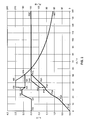
- FIG. 2 shows an example of a diagram showing the dependence of the lamp current and shows the lamp power from the burning voltage. Are shown two cases with different start-up behavior, controlled by two different ones Characteristics.
- the operating voltage UL is given in volts on the abscissa. On the left ordinate is the lamp current IL in amperes and the lamp power on the right ordinate PL stated in watts.
- the characteristic curve A remains valid.
- the Limit value remains between 32V and 53.5V via point I6A to point I7A Burning voltage constant at a value of 2.8A.
- point I7A reached, at which the lamp consumes the target power of approx. 150W.
- the increases Burning voltage continues, the lamp current is no longer limited by the limit determined by the characteristic curve A, but it follows the hyperbola for constant Power specified up to point I8C at an operating voltage of 140V is.
- High burning voltages are an indication of lamps that are near the end of their service life are. Therefore, the operating devices in question usually have a predefined one Threshold voltage for the burning voltage. If this threshold voltage for longer If the time is exceeded, the control gear switches off.
- the detection device sends a signal to the control device.
- a characteristic curve B is activated.
- the limit at 32V operating voltage is according to Characteristic curve B at 3.5A, which is why there is a jump from point I5A to point I5B.
- the limit value is independent of the operating voltage 3.5A. If the burning voltage continues to increase along the characteristic curve B, it hits in the Point I6B at approximately 43V on the hyperbole for constant power, as above described the power control begins to work.
- the operating voltage would be without switching at point I5A from characteristic A to characteristic B no longer rose significantly above 32V.
- the lamp would have the hyperbola for constant power and thus its target power not reached.
- the points P1A to P7A indicate the lamp currents in the points Characteristic curve A (I1A to I7A) belonging lamp power is shown.
- Points P5B and P6B show the lamp powers for the corresponding points I5B and I6B characteristic B. As the lamp current reaches the hyperbola for constant power the lamp power graph remains constant up to point P8C 150W.
- FIG. 3 shows an example of how the Change in the operating voltage in the time is evaluated and via the control device a change in lamp current in time.
- the change in the operating voltage over time is plotted on the abscissa is evaluated by the detection device.
- On the ordinate is the lamp current change plotted in the time that the control device at the corresponding Change in the operating voltage causes.
- the example according to FIG. 3 shows that in the start-up phase the lamp current is increased by 30 mA per second if the burning voltage does not change.
- the lamp current is left at the current value if the Burning voltage increased by one volt per second.
- the lamp current is per second reduced by 30 mA if the burning voltage increases by 2 volts per second elevated.
- FIG. 3 shows a linear relationship between the change in the operating voltage and Lamp current change specified. However, they are also non-linear and discontinuous Connections conceivable.
Landscapes
- Engineering & Computer Science (AREA)
- Power Engineering (AREA)
- Circuit Arrangements For Discharge Lamps (AREA)
- Multiple-Way Valves (AREA)
Abstract
Description
Die Erfindung betrifft ein Betriebsgerät und ein Verfahren zum Betreiben von Gasentladungslampen mit Elektroden. Insbesondere löst die Erfindung Probleme, die beim Anlauf von Gasentladungslampen auftreten.The invention relates to an operating device and a method for operating gas discharge lamps with electrodes. In particular, the invention solves problems that occur when starting gas discharge lamps.
Gasentladungslampen müssen durch eine hohe Spannung gezündet. Nach der Zündung erwärmt sich die Lampe während einer Anlaufphase von einer Starttemperatur auf eine Betriebstemperatur. Die Spannung, die nach der Zündung an einer Gasentladungslampe anliegt, wird Brennspannung genannt und ist in weiten Grenzen nicht wesentlich vom Lampenstrom abhängig. Die Brennspannung steigt während der Anlaufphase von einer Startbrennspannung bis zu einer Betriebsbrennspannung. Der Anlaufphase schließt sich bei bestimmungsgemäß funktionierenden Gasentladungslampen eine Betriebsphase an.Gas discharge lamps must be lit by a high voltage. After the ignition the lamp heats up from a start temperature during a start-up phase to an operating temperature. The voltage after ignition on a gas discharge lamp is called burning voltage and is not within wide limits depends essentially on the lamp current. The burning voltage increases during the start-up phase from a starting voltage to an operating voltage. The The start-up phase closes when the gas discharge lamps function as intended an operating phase.
In der Lampentechnik wird zwischen Hoch- und Niederdruckgasentladungsalmpen unterschieden. Bei Hochdruckgasentladungslampen im folgenden auch Lampen genannt, ist für die Funktionsweise wesentlich, dass während der Anlaufphase der Druck im Lampengefäß von einem Anfangsdruck bis zu einem Betriebsdruck ansteigt. Dies ist ein Grund, weshalb die im folgenden beschriebene Erfindung besonders vorteilhaft bei Hochdruckgasentladungslampen eingesetzt werden kann. Jedoch ist auch ein Einsatz bei Niederdruckgasentladungsalmpen möglich. In lamp technology, there is a distinction between high and low pressure gas discharge lamps distinguished. In the case of high-pressure gas discharge lamps, also referred to below as lamps, is essential for the functionality that during the start-up phase Pressure in the lamp vessel increases from an initial pressure to an operating pressure. This is one reason why the invention described below is special can advantageously be used in high-pressure gas discharge lamps. however use with low pressure gas discharge lamps is also possible.
Während der Betriebsphase ist es üblich, daß das Betriebsgerät die Leistung der Lampe auf eine Sollleistung regelt. Da während der Anlaufphase die Brennspannung niedrig ist, wäre bei reiner Leistungsregelung während der Anlaufphase ein hoher Lampenstrom nötig, um die Sollleistung einzustellen. Dieser Strom kann um ein vielfaches höher sein als der Lampenstrom während der Betriebsphase. Dies würde zu einer Zerstörung der Elektroden der Lampe führen. Deshalb wird im Stand der Technik der Strom den das Betriebsgerät während der Anlaufphase an die Lampe liefert auf einen konstanten Anlaufstrom begrenzt. Damit wird zumindest während eines ersten Abschnitts der Anlaufphase die Lampe mit dem konstanten Anlaufstrom gespeist. Im Verlauf der Anlaufphase steigt die Brennspannung. Erreicht die Brennspannung einen Wert der zusammen mit dem konstanten Strom die gewünschte Sollleistung ergibt, so beginnt die Leistungsregelung zu arbeiten. Beim weiteren Anstieg der Brennspannung wird durch die Leistungsregelung der Lampenstrom so weit reduziert, dass sich die Sollleistung einstellt. Die Anlaufphase ist abgeschlossen, wenn die Brennspannung den Wert der Betriebsbrennspannung erreicht hat. Die Bertriebsbrennspannung weist Exemplarstreuungen auf und ändert sich auch während der Lebensdauer einer Lampe. Die Betriebsbrennspannung wird daher definiert durch die Brennspannung die bei Sollleistung während eines Zeitbereichs im wesentlichen konstant bleibt. Der zu betrachtende Zeitbereich liegt beispielsweise bei einer Minute. Korreliert mit der Betriebsbrennspannung ist ein Betriebslampenstrom, der zusammen mit der Betriebsbrennspannung die Sollleistung ergibt.During the operating phase, it is common for the operating device to have the performance of the Lamp regulates to a target power. Since the operating voltage during the start-up phase low, would be a high one with pure power control during the start-up phase Lamp current required to set the target power. This current can be many times be higher than the lamp current during the operating phase. This would be too lead to destruction of the lamp electrodes. Therefore, in the prior art the current that the control gear supplies to the lamp during the start-up phase limited to a constant starting current. So at least during one In the first section of the start-up phase, the lamp is fed with the constant starting current. The internal voltage increases during the start-up phase. Reaches the burning voltage a value of the desired power, together with the constant current results, the power regulation begins to work. With further increase the lamp voltage is reduced so much by the power control, that the target output is established. The start-up phase is complete when the operating voltage has reached the value of the operating operating voltage. The Operational burning voltage shows sample variations and also changes during the life of a lamp. The operating burning voltage is therefore defined by the operating voltage, which is essentially the case for nominal power during a time range remains constant. The time range to be considered is, for example Minute. Correlated with the operating voltage is an operating lamp current that together with the operating combustion voltage gives the target power.
Für den Wert des Anlaufstroms ist folgendes zu beachten: Während der Anlaufphase muß soviel Leistung in die Lampe eingekoppelt werden, dass der Druck in der Lampe und damit die Lampenspannung stetig ansteigt, bis die Betriebsbrennspannung erreicht ist. Andernfalls kann der Fall eintreten, dass die Lampe während der Anlaufphase in einem stabilen Zustand verharrt und die Sollleitung nicht erreicht wird. Um diesen Fall sicher auszuschließen, wird im Stand der Technik ein Anlaufstrom gewählt, der deutlich über dem Betriebslampenstrom liegt. Dies wird in der Schrift US 5,083,065 (Sakata) dargestellt. Ein Aspekt bei der Wahl des Anlaufstroms ist auch der Wunsch nach einer möglichs kurzen Anlaufphase, um in möglichst kurzer Zeit einen Solllichtstrom zu erreichen. The following must be observed for the value of the starting current: During the starting phase So much power must be coupled into the lamp that the pressure in the lamp and thus the lamp voltage rises steadily until the operating voltage is reached. Otherwise it may happen that the lamp during the start-up phase remains in a stable state and the target line is not reached. Around in the prior art, a starting current is selected to reliably rule out this case, which is significantly higher than the operating lamp current. This is documented in US 5,083,065 (Sakata). One aspect when choosing the starting current is also the desire for a start-up phase that is as short as possible, in the shortest possible time to achieve a target luminous flux.
Ein hoher Anlaufstrom stellt jedoch eine starke Belastung der Elektroden dar, was zu Schädigung der Elektroden führt und damit die Lebensdauer einer Lampe reduziert. Geschädigt werden die Elektroden entweder durch Überhitzung, was zu Aufschmelzen und Abbrand führt oder durch sogenanntes Sputtern, das veruracht wird durch Ionen, die mit hoher Geschwindigkeit eine Elektode treffen.A high starting current, however, places a heavy load on the electrodes, which leads to Damage to the electrodes leads and thus reduces the life of a lamp. The electrodes are damaged either by overheating, which leads to melting and burns or by so-called sputtering, which is caused Ions hitting an electrode at high speed.
Es ist Aufgabe der vorliegenden Erfindung, ein Betriebsgerät und ein Verfahren zum Betrieb von Gasentladungslampen bereit zu stellen, das eine Anlaufphase aufweist, die einerseits sicher stellt, dass die Lampe in eine Betriebsphase geführt wird und andererseits eine minimale Belastung der Elektroden bewerkstelligt.It is an object of the present invention, an operating device and a method for To provide operation of gas discharge lamps which has a start-up phase, which on the one hand ensures that the lamp is brought into an operating phase and on the other hand, a minimal load on the electrodes is achieved.
Diese Aufgabe wird durch ein Betriebsgerät zum Betrieb von Gasentladungslampen gelöst, das folgende Merkmale aufweist:
- Eine Regeleinrichtung, die dazu geeignet ist, die Leistung von angeschlossenen Gasentladungslampen auf eine Sollleistung zu regeln,
- eine Stelleinrichtung die dazu geeignet ist, einen Lampenstrom von angeschlossenen Gasentladungslampen auf einen Grenzwert zu begrenzen,
- eine Detektionseinrichtung, die so ausgelegt ist, dass sie an eine Steuereinrichtung ein Signal abgibt, falls eine Grenzwerteinstellung zu gering ist, um eine angeschlossene Lampe in einen Zustand zu versetzen, bei dem die Lampe die Sollleistung aufnimmt,
- die Steuereinrichtung ist so ausgelegt, dass sie der Stelleinrichtung den Grenzwert vorgibt und den Grenzwert erhöht, falls die Detektionseinrichtung ein Signal an die Steuereinrichtung sendet.
- A regulating device which is suitable for regulating the power of connected gas discharge lamps to a target power,
- an actuating device which is suitable for limiting a lamp current of connected gas discharge lamps to a limit value,
- a detection device which is designed such that it emits a signal to a control device if a limit value setting is too low to put a connected lamp into a state in which the lamp consumes the desired power,
- the control device is designed such that it specifies the limit value for the control device and increases the limit value if the detection device sends a signal to the control device.
Besonders vorteilhafte Ausgestaltungen der Erfindung finden sich in den abhängigen Ansprüchen.Particularly advantageous embodiments of the invention can be found in the dependent ones Claims.
Insbesondere bei sogenannten Ultra-Hochdrucklampen, die vorwiegend in Projektionsanwendungen
wie z. B. Beamer eingesetzt werden, hat sich gezeigt, dass die
Feinstruktur der Elektroden-Oberfläche wesentlichen Einfluss auf die Lebensdauer
und das Flackern der Lampe hat. In der Schrift DE 100 21 537 (Derra) sind derartige
Feinstrukturen beschrieben. Diese Feinstrukturen werden entweder bei der Fertigung
der Lampe erzeugt oder sie ergeben sich durch einen dafür geeigneten Betrieb der
Lampe während der Betriebsphase. Die hier beschriebene Erfindung verhindert, dass
die genannten Feinstrukturen in der Anlaufphase durch einen überhöhten Anlaufstrom
zerstört werden.Especially with so-called ultra-high pressure lamps, which are mainly used in projection applications
such as B. Beamer can be used, it has been shown that the
Fine structure of the electrode surface has a significant influence on the service life
and the lamp flickers. In the
Erfindungsgemäß beginnt die Anlaufphase mit einem niedrigen Anlaufstrom, dessen Wert so gewählt wird, dass eine Schädigung der Elektroden einer angeschlossenen Lampe ausgeschlossen ist. Wird mit dem zunächst eingestellten Anlaufstrom kein Zustand der Lampe erreicht, bei dem die Lampe die Sollleistung aufnimmt, so wird erfindungsgemäß der Anlaufstrom erhöht.According to the invention, the starting phase begins with a low starting current, the Value is chosen so that damage to the electrodes of a connected Lamp is excluded. With the starting current initially set, none The lamp reaches the state in which the lamp consumes the desired power according to the invention, the starting current is increased.
Im folgenden soll die Erfindung anhand von Ausführungsbeispielen unter Bezugnahme auf Zeichnungen näher erläutert werden. Es zeigen:
Figur 1- Blockschaltbild eines Ausführungsbeispiels für ein erfindungsgemäßes Betriebsgerät,
Figur 2- Diagramm, das die Abhängigkeit des Lampenstroms und der Lampenleistung von der Brennspannung bei unterschiedlichem Anlaufverhalten darstellt.
Figur 3- Diagramm, das die Abhängigkeit der Lampenstromänderung in der Zeit von der Brennspannungsänderung in der Zeit darstellt.
- Figure 1
- Block diagram of an embodiment for an operating device according to the invention,
- Figure 2
- Diagram showing the dependency of the lamp current and the lamp power on the operating voltage with different starting behavior.
- Figure 3
- Diagram showing the dependence of the lamp current change in time on the change in the operating voltage in time.
In Figur 1 ist ein Blockschaltbild eines Ausführungsbeispiels für ein erfindungsgemäßes Betriebsgerät dargestellt, das zum Betrieb von Hochdruck-Gasentladungslampen geegnet ist. Der grundsätzliche Aufbau und die grundsätzliche Funktionsweise eines derartigen Betriebsgeräts ist in der Schrift WO 95/35645 (Derra) beschrieben. Im folgenden werden die einzelnen Blöcke kurz beschrieben.In Figure 1 is a block diagram of an embodiment of an inventive Operating device shown for the operation of high-pressure gas discharge lamps is blessed. The basic structure and the basic Operation of such an operating device is described in WO 95/35645 (Derra). The individual blocks are briefly described below.
Block 1 enthält eine Gleichspannungsversorgung, die ihre Energie im allgemeinen
aus einer Netzspannungsversorgung bezieht. Der Wert der geliefeten Gleichspannung
liegt über der Brennspannung einer angeschlossenen Lampe 6.
Die Gleichsapnnungsversorgung speist einen Tiefsetzer 2, der den von der Gleichspannungsversorgung
gelieferten Spannungswert auf einen Wert abtransformiert, der
der Brennspannung einer angeschlossenen Lampe 6 entspricht. Der Tiefsetzer 2 enthält
eine Stelleinrichtung, mit der der Lampenstrom eingestellt werden kann. Dies
geschieht durch die Wahl der Spannung, die am Ausgang des Tiefsetzers eingestellt
wird.The DC voltage supply feeds a step-down
Eine Einstellmöglichkeit besteht meist durch eine sogenannte Pulsweitenmodulation
(PWM). Diese bestimmt das Verhältnis von Einschalt- zu Ausschaltdauer von elektronischen
Schaltern, die im Tiefsetzer 2 enthalten sind.One setting option is usually a so-called pulse width modulation
(PWM). This determines the ratio of on-time to off-time of electronic ones
Switches included in the step-down
Die Ausgestaltung des Tiefsetzers 2 kann der allgemeinen Literatur zur Leistungselektronik
entnommen werden. In WO 95/35645 (Derra) ist eine Topologie mit einem
Schalter gewählt. Es ist jedoch auch eine Ausführung mit mehreren Schaltern
möglich, wie sie z. B. eine Halbbrücke darstellt. Der Tiefsetzer 2 enthält eine Drossel,
die als Strombegrenzung dient. Damit bekommt der Tiefsetzer 2 eine Charakteristik
die einer einstellbaren Stromquelle für den Lampenstrom entspricht.The design of the
Je nach gewählter Topologie liefert der Tiefsetzter 2 einen Gleichstrom oder einen
Wechselstrom. Für den Fall, dass der Tiefsetzer 2 einen Wechselstrom liefert, wird
der Ausgang des Tiefsetzers 2 in einen Gleichrichter 3 eingespeist, der an seinem
Ausgang einen Gleichstrom liefert. Der Gleichrichter 3 kann entfallen, falls der Tiefsetzer
2 einen Gleichstrom liefert.Depending on the selected topology, the step-down
Der Gleichstrom aus dem Gleichrichter 3 oder dem Tiefsetzer 2 wird in eine Vollbrücke
4 eingespeist, die den Gleichstrom in einen rechteckförmigen Wechselstrom
umformt. Die Frequenz des rechteckförmigen Wechselstroms ist im Vergleich zu
üblichen Frequenzen bei denen der Tiefsetzer 2 arbeitet niederig und liegt bei Werten
zwischen 50 Hz und 1 kHz. Die Umformung in rechteckförmigen Wechselstrom ist
bei Anwendungen nötig, die Wechselstromlampen betreiben und einen gleichförmigen
Lichtstrom benötigen. Beispiele für derartige Anwendungen sind Beamer und
Rückprojektionsfernseher. Der erfindungsgemäße, elektrodenschonende Anlauf der
Lampe, kann jedoch auch auf Gleichstromlampen oder auf Wechselstromlampen, die
mit nicht rechteckförmigem Wechselstrom betreiben werden, angewendet werden. Je
nach Anwendung kann demnach der Block 3 oder 4 oder beide entfallen.The direct current from the
Zwischen die Vollbrücke 4 und die Lampe 6 ist eine Zündeinheit 5 geschaltet, die die
zur Zündung der Lampe nötige Spannung liefert. Nach der Zündung der Lampe übernimmt
die Zündeinheit 5 üblicherweise keine Funktion mehr.Between the
Eine Kontrolleinheit 7 ist mit mit dem Tiefsetzer 2, dem Gleichrichter 3, der Vollbrücke
4 und der Zündeinheit 5 verbunden. Die Kontrolleinheit 7 enthält die Steuereinrichtung,
die Regeleinrichtung, die Detektionseinrichtung sowie Messeinrichtungen
zur Erfassung von Betriebsparametern (z.B. Brennspannung, Lampenstrom) und
eine Einrichtung zum Speichern von lampentypischen Daten und Kennlinien. Die
einzelnen Einrichtungen sind in der Kontrolleinheit 7 zusammengefasst, da die Kontrolleinheit
7 meist einen Microkontroller enthält, der die Funktion mehrerer oder
aller Einrichtungen in sich vereint. In vielen Fällen ist auch die Realisierung einer
Einrichtung entweder durch Hardware oder durch Software möglich. In zunehmendem
Maße werden Steuer- und Regelaufgaben durch Software übernommen, da diese
Lösung kostengünstig und flexibel ist.A
Alle Verbindungen, die zur Kontrolleinheit 7 führen, können sowohl Ein- als auch
Ausgänge sein. Als Eingänge geschaltet können die Verbindungen Information über
die Brennspannung und über den Lampenstrom beliebig aus einem der Blöcke 2-5
der Kontrolleinheit 7 zuführen.All connections leading to the
Als Ausgänge geschaltet steuern die Verbindungen koordiniert duch die Kontrolleinheit
7 Zündung, Anlauf, Betrieb und Abschalten des Betriebsgeräts.Connected as outputs, the connections are coordinated by the
Die Regeleinrichtung, die in der Kontrolleinheit 7 enthalten ist, berechnet aus dem
Lampenstrom und der Brennspannung die Lampenleistung und vergleicht sie mit
einer abgespeicherten Sollleistung für die zu betreibende Lampe. Ist die Lampenleistung
geringer als die Sollleistung, so erhöht die Steuereinrichtung über die Stelleinrichtung
den Lampenstrom so lange, Lampenleistung und Sollleistung übereinstimmen.The control device, which is contained in the
Für einen erfindungsgemäßen Anlauf stellt die Steuereinrichtung, die in der Kontrolleinheit
7 enthalten ist, über eine Stelleirichtung, die im Tiefsetzer 2 enthalten ist,
nach der Zündung zunächst einen Grenzwert für den Lampenstrom ein. Die Lampe
befindet sich in der Anlaufphase weshalb der Lampenstrom in dieser Phase auch
Anlaufstrom genannt wird. Erfindungsgemäß ist der Grenzwert so gewählt dass eine
Schädigung der Elektroden ausschgeschlossen ist. Der Grenzwert ist abhängig von
der Lampe, die betrieben werden soll. Ein meist aus Versuchsreihen ermittelter Wert
ist in der Kontrolleinheit 7 abgespeichert.For a start-up according to the invention, the control device, which is in the
Der Grenzwert kann während der Anlaufphase konstant sein, was eine einfache Realisierung
ermöglicht. Es hat sich jedoch gezeigt, dass ein bezüglich der Belastung der
Elektroden und der Stabilität des Plasmabogens der Lampe der Anlauf optimiert
werden kann, wenn der Grenzwert für den Lampenstrom abhängig von der Brennspannung
gewählt wird. Die optimale Abhängigkeit wird in Versuchen ermittelt und
in Form einer Kennlinie in der Kontrolleinheit 7 abgespeichert.The limit value can be constant during the start-up phase, which is a simple implementation
allows. However, it has been shown that a with regard to the load of the
Electrodes and the stability of the plasma arc of the lamp optimized for startup
can be if the limit for the lamp current depends on the burning voltage
is chosen. The optimal dependency is determined in experiments and
stored in the form of a characteristic curve in the
Mittels einer Messeinrichtung ermittelt also die Kontrolleinheit 7 zunächst die
Brennspannung und stellt den dazugehörigen optimalen Grenzwert für den Lampenstrom
ein. Im Lauf der Anlaufphase erhöht sich die Brennspannung immer weiter
und erreicht im Idealfall einen Wert, der zu einer Lampenleistung führt, die der Sollleistung
entspricht und die Lampe schließlich in die Betriebsphase übergeht. Eine
Änderung des konstanten oder von der abgespeicherten Kennlinie vorgegebenen
Grenzwerts ist in diesem Idealfall nicht nötig.The
Um die Elektroden zu schonen wird jedoch ein möglichst niedriger Grenzwert gewählt, der zu einem Fall führen kann, der vom Idealfall abweicht. Die Leistung, die im nicht idealen Fall in der Lampe umgesetzt wird ist so gering, dass die Brennspannung nicht soweit ansteigt, dass in der Lampe die Sollleistung erreicht. Vielmehr verharrt die Brennspannung auf einem Wert und steigt nicht mehr weiter an.In order to protect the electrodes, however, the lowest possible limit value is selected, that can lead to a case that deviates from the ideal case. The performance that in the non-ideal case the lamp is implemented so low that the burning voltage does not rise to such an extent that the lamp achieves the desired output. Much more the burning voltage remains at a value and no longer increases.
Erfindungsgemäß erkennt eine Detektionseinrichtung diesen Fall und gibt ein Signal an die Steuereinrichtung. Diese veranlasst eine Erhöhung des Grenzwerts, worauf die Brennspannung wieder zu steigen beginnt. Meist genügt eine einmalige Erhöhung des Grenzwerts, um die Lampe in die Betriebsphase zu führen. Es ist jedoch auch möglich, dass die Detektionseinrichtung mehrmals erkennt, dass die Lampe die Sollleistung nicht erreichen wird und eine weitere Erhöhung des Grenzwerts über ein Signal an die Steuereinrichtung auslöst.According to the invention, a detection device recognizes this case and emits a signal to the control device. This causes an increase in the limit, whereupon the Burning voltage begins to rise again. A one-off increase is usually sufficient the limit value to bring the lamp into the operating phase. However, it is also possible that the detection device recognizes several times that the lamp the target power will not reach and a further increase in the limit above one Triggers signal to the control device.
Eine Erhöhung des Grenzwerts kann derart ausgestaltet sein, dass die Steuereinrichtung der Stelleinrichtung ausgehend von einem konstantem Grenzwert einen höheren konstanten Grenzwert vorgibt. Diese Lösung kann einfach realisiert werden.An increase in the limit value can be configured such that the control device the control device a higher based on a constant limit specifies a constant limit. This solution can be easily implemented.
Um sicher zu gehen, dass nach dem ersten Empfang eines Signals der Detektionseinrichtung die Lampe in die Betriebsphase übergeht kann nach dem ersten Empfang eines Signals der Detektionseinrichtung die Steuereinrichtung auch so ausgelegt werden, dass sie der Stelleinrichtung einen schrittweise oder kontinuierlich ansteigenden Grenzwert vorgibt.To be sure that after the first reception of a signal from the detection device the lamp can go into the operating phase after the first reception a signal from the detection device, the control device is also designed in this way that the actuating device has a gradually or continuously increasing Prescribes limit.
Wie oben beschrieben sind auch Steuereinrichtungen möglich, bei denen der Grenzwert über eine abgespeicherte Kennlinie von der Brennspannung abhängt. Bei einer derartigen Steuereinrichtung löst ein Signal der Detektionseinrichtung ein Abweichen von der abgespeicherten Kennlinie aus. Die Kontrolleinheit 7 kann mehere abgespeicherte Kennlinien aufweisen, wobei jeweils eine aktiv geschaltet und für die Steuereinrichtung gültig ist. Begonnen wird die Anlaufphase mit einer Kennlinie, die die niedrigsten Grenzwerte aufweist. Bei Empfang eines Signals von der Detektionseinrichtung schaltet die Steuereinrichtung eine weitere Kennlinie aktiv, die höhre Grenzwerte aufweist. Diese Realisierung der vorliegenden Erfindung ist zwar aufwändiger, als das jeweilige Einstellen konstanter Grenzwerte, ermöglicht aber einen Anlauf der Lampe, wie er anhand von Versuchsreihen, die mit der betreffenden Lampe durchgeführt wurden, optimal ist. Als Kriterien dafür werden herangezogen:
- Geringst mögliche Schädigung der Elektroden und damit maximale Lebensdauer
- Kurze Anlaufphase
- Stabilität des Plasmabogens in der Lampe
- Lowest possible damage to the electrodes and thus maximum service life
- Short start-up phase
- Stability of the plasma arc in the lamp
Für die Ausführung der Detektionseinrichtung gibt es mehrere Möglichkeiten:There are several options for executing the detection device:
Bei einer einfachen Ausführung der Detektionseinrichtung misst eine Zeitmesseinrichtung die Zeit, die seit dem Beginn der Anlaufphase verstrichen ist. Nach einer voreingestellten Zeit, gibt die Detektionseinrichtung ein Signal an die Steuereinrichtung. Die voreingestellte Zeit wird in der Regel durch Versuchsreihen mit der zu betreibenden Lampe bestimmt. Hat die Lampe nach der voreingestellten Zeit die Sollleistung noch nicht erreicht, so wird mittels der Steuereinrichtung ein höherer Grenzwert wirksam. Hat die Lampe nach der voreingestellten Zeit die Sollleistung bereits erreicht, so würde die Steuereinrichtung zwar einen höheren Lampenstrom zulassen, die Regeleinrichtung stellt jedoch einen Lampenstrom ein, der zusammen mit der Brennspannung die Sollleistung ergibt.In a simple embodiment of the detection device, a time measuring device measures the time that has passed since the start of the start-up phase. After a preset time, the detection device sends a signal to the control device. The preset time is usually determined by series of tests with the operating lamp determined. After the preset time the lamp has the If the target power has not yet been reached, the control device uses a higher one Limit effective. Does the lamp have the desired output after the preset time already reached, the control device would indeed have a higher lamp current allow, however, the control device sets a lamp current that together with the operating voltage results in the target power.
Eine weitere Möglichkeit zur Ausführung der Detektionseinrichtung besteht darin, dass die Detektionseinrichtung den Anstieg der Brennspannung erfasst. Je schneller die Brennspannung ansteigt, desto größer ist die Wahrscheinlichkeit, dass die Lampe in die Betriebsphase übergeht. Sobald der Anstieg der Brennspannung unter einem vorgegebenem Wert liegt, sendet die Detektionseinrichtung ein Signal an die Steuereinrichtung. Der vorgegebene Wert für den Anstieg der Brennspannung wird in der Regel durch Versuchsreihen mit der zu betreibenden Lampe bestimmt. Gegenüber der zuerst beschrieben Ausführung der Detektionseinrichtung hat die zweite Ausführung den Vorteil, dass sie früher erkennen kann, dass ein eingestellter Grenzwert zu niedrig ist und somit die Anlaufphase verkürzen werden kann.Another option for executing the detection device is to that the detection device detects the rise in the operating voltage. The faster the burning voltage increases, the greater the likelihood that the lamp goes into the operating phase. As soon as the rise in the burning voltage under one predetermined value, the detection device sends a signal to the control device. The specified value for the increase in the operating voltage is in usually determined by series of tests with the lamp to be operated. Across from the version of the detection device described first has the second Execution the advantage that it can recognize earlier that a set Limit is too low and the start-up phase can be shortened.
In Figur 2 ist beispielhaft ein Diagramm darstellt, das die Abhängigkeit des Lampenstroms und der Lampenleistung von der Brennspannung zeigt. Dargetellt sind zwei Fälle mit unterschiedlichem Anlaufverhalten, gesteuert durch zwei unterschiedliche Kennlinien.FIG. 2 shows an example of a diagram showing the dependence of the lamp current and shows the lamp power from the burning voltage. Are shown two cases with different start-up behavior, controlled by two different ones Characteristics.
Auf der Abszisse ist die Brennspannung UL in Volt angegeben. Auf der linken Ordinate ist der Lampenstrom IL in Ampere und auf der rechten Ordinate die Lampenleistung PL in Watt angegeben.The operating voltage UL is given in volts on the abscissa. On the left ordinate is the lamp current IL in amperes and the lamp power on the right ordinate PL stated in watts.
Zunächst wird die Abhängigkeit des Lampenstroms von der Brennspannung erläutert. Beginnend bei einer Brennspannung von 0V bis ca. 17V schreibt eine abgespeicherte Kennlinie A für den Lampenstrom einen konstanten Grenzwert von 2,5A vor. Dies wird durch das Kennlinienstück zwischen den Punkten I1A und I2A beschrieben. Steigt die Brennspannung im Punkt I2A über einen Wert von ca. 17V an, so erhöht sich der Grenzwert linear bis 3,2A, bis die Brennspannung im Punkt I3A 23V erreicht. Von 23V bis 30V Brennsapnnung bleibt der Grenzwert konstant bei 3,2A. Über 30V Brennspannung wird im Punkt I4A der Grenzwert wieder linear zurückgenommen bis zu einem Grenzwert von 2,8A bei 32V im Punkt I5A. Die Überhöhung des Grenzwerts im Bereich zwischen 22V und 32V dient der Stabilisierung des Plasmabogens der Lampe.The dependence of the lamp current on the operating voltage is first explained. Starting with a burning voltage of 0V to approx. 17V, a saved one writes Characteristic A for the lamp current has a constant limit of 2.5A. This is described by the characteristic curve between points I1A and I2A. If the burning voltage rises above a value of approx. 17 V at point I2A, then the limit increases linearly to 3.2A until the burning voltage at point I3A 23V reached. The limit value remains constant at 3.2A from 23V to 30V. The threshold value is linearly withdrawn again at point I4A above 30 V operating voltage up to a limit of 2.8A at 32V at point I5A. The exaggeration The limit in the range between 22V and 32V serves to stabilize the Plasma arc of the lamp.
Falls die Detektionseinrichtung beim Erreichen des Punkts I5A noch kein Signal an die Steuereinrichtung gesendet hat, bleibt die Kennlinie A weiterhin gültig. Der Grenzwert bleibt über den Punkt I6A bis zum Punkt I7A zwischen 32V und 53,5V Brennspannung konstant bei einem Wert von 2,8A. Beim Punkt I7A ist ein Zustand erreicht, bei dem die Lampe die Sollleistung von ca. 150W aufnimmt. Steigt die Brennspannung weiter an, so wird der Lampenstrom nicht mehr durch den Grenzwert bestimmt, den die Kennlinie A vorgibt, sondern er folgt der Hyperbel für kontante Leistung, die bis zum Punkt I8C bei einer Brennspannung von 140V angegeben ist. If the detection device does not yet emit a signal when point I5A is reached has sent the control device, the characteristic curve A remains valid. The Limit value remains between 32V and 53.5V via point I6A to point I7A Burning voltage constant at a value of 2.8A. There is a condition at point I7A reached, at which the lamp consumes the target power of approx. 150W. The increases Burning voltage continues, the lamp current is no longer limited by the limit determined by the characteristic curve A, but it follows the hyperbola for constant Power specified up to point I8C at an operating voltage of 140V is.
Hohe Brennspannungen sind ein Indiz für Lampen, die nahe ihrem Lebensdauerende sind. Deshalb besitzten die in Rede stehenden Betriebsgeräte meist eine vorgegebene Schwellspannung für die Brennspannung. Falls diese Schwellspannung für längere Zeit überschritten wird schaltet das Betriebsgerät ab.High burning voltages are an indication of lamps that are near the end of their service life are. Therefore, the operating devices in question usually have a predefined one Threshold voltage for the burning voltage. If this threshold voltage for longer If the time is exceeded, the control gear switches off.
Im Punkt I5A spaltet sich die Kennlinie auf. Im Beispiel nach Figur 2 wird nun angenommen, dass zum Zeitpunkt, bei dem die Brennspannung den Punkt I5A erreicht hat, die Detektionseinrichtung an die Steuereinrichtung ein Signal sendet. Dadurch wird eine Kennlinie B aktiviert. Der Grenzwert bei 32V Brennspannung liegt gemäß Kennlinie B bei 3,5A, weshalb ein Sprung vom Punkt I5A zum Punkt I5B erfolgt. Gemäß der Kennlinie B liegt der Grenzwert unabhängig von der Brennspannung bei 3,5A. Steigt die Brennspannung entlang der Kennlinie B weiter an, so trifft sie im Punkt I6B bei ca. 43V auf die Hyperbel für konstante Leistung, bei der wie oben beschrieben die Leistungsregelung zu wirken beginnt.The characteristic splits at point I5A. In the example according to FIG. 2, it is now assumed that at the time when the burning voltage reaches the point I5A has, the detection device sends a signal to the control device. Thereby a characteristic curve B is activated. The limit at 32V operating voltage is according to Characteristic curve B at 3.5A, which is why there is a jump from point I5A to point I5B. According to characteristic curve B, the limit value is independent of the operating voltage 3.5A. If the burning voltage continues to increase along the characteristic curve B, it hits in the Point I6B at approximately 43V on the hyperbole for constant power, as above described the power control begins to work.
Im aufgezeigten Beispiel wäre die Brennspannung ohne Umschalten im Punkt I5A von der Kennlinie A zur Kennlinie B nicht mehr wesentlich über 32V angestiegen. Die Lampe hätte die Hyperbel für konstante Leistung und somit ihre Sollleistung nicht erreicht.In the example shown, the operating voltage would be without switching at point I5A from characteristic A to characteristic B no longer rose significantly above 32V. The lamp would have the hyperbola for constant power and thus its target power not reached.
Durch die Punkte P1A bis P7A ist die zu den Lampenströmen in den Punkten der Kennlinie A (I1A bis I7A) gehörende Lampenleistung aufgezeigt. Die Punkte P5B und P6B zeigen die Lampenleistungen zu den entprechenden Punkten I5B und I6B der Kennlinie B. Sowie der Lampenstrom die Hyperbel für konstante Leistung erreicht bleibt der Graph für die Lampenleistung bis zum Punkt P8C konstant bei 150W.The points P1A to P7A indicate the lamp currents in the points Characteristic curve A (I1A to I7A) belonging lamp power is shown. Points P5B and P6B show the lamp powers for the corresponding points I5B and I6B characteristic B. As the lamp current reaches the hyperbola for constant power the lamp power graph remains constant up to point P8C 150W.
In Figur 3 ist ein Beispiel dafür dargestellt, wie über die Detektionseinrichtung die Änderung der Brennspannung in der Zeit ausgewertet wird und über die Steuereinrichtung eine Änderung des Lampenstroms in der Zeit bewirkt.FIG. 3 shows an example of how the Change in the operating voltage in the time is evaluated and via the control device a change in lamp current in time.
Auf der Abszisse ist die Änderung der Brennspannung in der Zeit aufgetragen, die von der Detektionseinrichtung ausgewertet wird. Auf der Ordinate ist die der Lampenstromänderung in der Zeit aufgetragen, die die Steuereinrichtung bei der entsprechenden Änderung der Brennspannung bewirkt.The change in the operating voltage over time is plotted on the abscissa is evaluated by the detection device. On the ordinate is the lamp current change plotted in the time that the control device at the corresponding Change in the operating voltage causes.
Dem Beispiel nach Figur 3 ist zu entnehmen, dass in der Anlaufphase der Lampenstrom pro Sekunde um 30 mA erhöht wird, falls sich die Brennspannung nicht ändert. Der Lampenstrom wird auf dem momentanen Wert belassen, falls sich die Brennspannung pro Sekunde um ein Volt erhöht. Der Lampenstrom wird pro Sekunde um 30 mA reduziert, falls sich die Brennspannung pro Sekunde um 2 Volt erhöht.The example according to FIG. 3 shows that in the start-up phase the lamp current is increased by 30 mA per second if the burning voltage does not change. The lamp current is left at the current value if the Burning voltage increased by one volt per second. The lamp current is per second reduced by 30 mA if the burning voltage increases by 2 volts per second elevated.
In Figur 3 ist ein linearer Zusammenhang zwischen Brennspannungsänderung und Lampenstromänderung vorgegeben. Es sind jedoch auch nichtlineare und unstetige Zusammenhänge denkbar.FIG. 3 shows a linear relationship between the change in the operating voltage and Lamp current change specified. However, they are also non-linear and discontinuous Connections conceivable.
Sinkt die Brennspannung oder steigt sie schneller als 2 Volt pro Sekunde, so wird eine maximale Änderung von 30 mA pro Sekunde vorgegeben, im ersten Fall steigend, im zweiten Fall fallend. Die maximale Änderung kann je nach Lampentyp und Anwendungsfall von 30 mA pro Sekunde abweichen.If the burning voltage drops or rises faster than 2 volts per second, then a maximum change of 30 mA per second is specified, increasing in the first case, falling in the second case. The maximum change can vary depending on the lamp type and Use case deviate from 30 mA per second.
Claims (11)
Applications Claiming Priority (2)
| Application Number | Priority Date | Filing Date | Title |
|---|---|---|---|
| DE10319950 | 2003-05-02 | ||
| DE10319950A DE10319950A1 (en) | 2003-05-02 | 2003-05-02 | Operating device and method for operating gas discharge lamps |
Publications (3)
| Publication Number | Publication Date |
|---|---|
| EP1476003A2 true EP1476003A2 (en) | 2004-11-10 |
| EP1476003A3 EP1476003A3 (en) | 2005-03-09 |
| EP1476003B1 EP1476003B1 (en) | 2008-08-06 |
Family
ID=32981217
Family Applications (1)
| Application Number | Title | Priority Date | Filing Date |
|---|---|---|---|
| EP04008068A Expired - Lifetime EP1476003B1 (en) | 2003-05-02 | 2004-04-02 | Power supply and method for driving discharge lamps |
Country Status (9)
| Country | Link |
|---|---|
| US (1) | US7038401B2 (en) |
| EP (1) | EP1476003B1 (en) |
| JP (1) | JP4411130B2 (en) |
| KR (1) | KR101069476B1 (en) |
| CN (1) | CN100551198C (en) |
| AT (1) | ATE404037T1 (en) |
| CA (1) | CA2465389C (en) |
| DE (2) | DE10319950A1 (en) |
| TW (1) | TWI362899B (en) |
Cited By (2)
| Publication number | Priority date | Publication date | Assignee | Title |
|---|---|---|---|---|
| WO2007065814A1 (en) * | 2005-12-06 | 2007-06-14 | Osram Gesellschaft mit beschränkter Haftung | Method for the detection of a fault during the operation of high-pressure discharge lamps on ballasts |
| EP2247169A1 (en) * | 2009-04-28 | 2010-11-03 | Osram Gesellschaft mit Beschränkter Haftung | Method and electronic pre-switching device for operating a high pressure discharge lamp |
Families Citing this family (5)
| Publication number | Priority date | Publication date | Assignee | Title |
|---|---|---|---|---|
| JP4211694B2 (en) * | 2004-06-24 | 2009-01-21 | セイコーエプソン株式会社 | Light source driving method and projector |
| DE102004061294B4 (en) * | 2004-12-20 | 2020-03-19 | Tridonic Gmbh & Co Kg | Method for programming an operating device for lamps, interface for an operating device for lamps and operating device for lamps |
| WO2010052641A2 (en) * | 2008-11-07 | 2010-05-14 | Philips Intellectual Property & Standards Gmbh | Providing power to gas discharge lamp |
| DE102013219694A1 (en) * | 2013-09-30 | 2015-04-02 | Automotive Lighting Reutlingen Gmbh | Method for operating a gas discharge lamp of a light module |
| CN104955198B (en) * | 2014-03-27 | 2017-07-21 | 苏州纽克斯电源技术股份有限公司 | A kind of highly integrated Digital Agriculture light filling equipment |
Citations (4)
| Publication number | Priority date | Publication date | Assignee | Title |
|---|---|---|---|---|
| US5481163A (en) * | 1993-08-03 | 1996-01-02 | Mitsubishi Denki Kabushiki Kaisha | Discharge lamp current controlling circuit |
| US5907742A (en) * | 1997-03-09 | 1999-05-25 | Hewlett-Packard Company | Lamp control scheme for rapid warmup of fluorescent lamp in office equipment |
| US6051939A (en) * | 1995-09-26 | 2000-04-18 | Robert Bosch Gmbh | Method and apparatus for controlling the power of a high-pressure gas-discharge lamp |
| US6153987A (en) * | 1996-06-07 | 2000-11-28 | Koito Manufacturing Co., Ltd. | Lighting circuit for discharge lamp |
Family Cites Families (10)
| Publication number | Priority date | Publication date | Assignee | Title |
|---|---|---|---|---|
| JPH03138894A (en) | 1989-10-23 | 1991-06-13 | Nissan Motor Co Ltd | Lighting device for discharge lamp |
| US5047695A (en) * | 1990-02-20 | 1991-09-10 | General Electric Company | Direct current (DC) acoustic operation of xenon-metal halide lamps using high-frequency ripple |
| JP3196206B2 (en) * | 1990-09-25 | 2001-08-06 | 東芝ライテック株式会社 | Discharge lamp lighting device |
| TW339496B (en) | 1994-06-22 | 1998-09-01 | Philips Electronics Nv | Method and circuit arrangement for operating a high-pressure discharge lamp |
| US5623187A (en) * | 1994-12-28 | 1997-04-22 | Philips Electronics North America Corporation | Controller for a gas discharge lamp with variable inverter frequency and with lamp power and bus voltage control |
| DE19708783C1 (en) * | 1997-03-04 | 1998-10-08 | Tridonic Bauelemente | Method and device for regulating the operating behavior of gas discharge lamps |
| DE10084850T1 (en) * | 1999-07-26 | 2002-06-27 | Microlights Ltd | Improvements to and related to electric lights |
| US6181076B1 (en) * | 1999-08-19 | 2001-01-30 | Osram Sylvania Inc. | Apparatus and method for operating a high intensity gas discharge lamp ballast |
| DE10021537A1 (en) | 2000-05-03 | 2001-11-08 | Philips Corp Intellectual Pty | Method and device for operating a gas discharge lamp |
| JP2003151787A (en) * | 2001-08-29 | 2003-05-23 | Harison Toshiba Lighting Corp | High pressure electric discharge lamp lighting device and headlight device for automobile |
-
2003
- 2003-05-02 DE DE10319950A patent/DE10319950A1/en not_active Withdrawn
-
2004
- 2004-04-02 DE DE502004007759T patent/DE502004007759D1/en not_active Expired - Lifetime
- 2004-04-02 AT AT04008068T patent/ATE404037T1/en not_active IP Right Cessation
- 2004-04-02 EP EP04008068A patent/EP1476003B1/en not_active Expired - Lifetime
- 2004-04-09 TW TW093109898A patent/TWI362899B/en not_active IP Right Cessation
- 2004-04-23 US US10/830,048 patent/US7038401B2/en not_active Expired - Lifetime
- 2004-04-28 CA CA2465389A patent/CA2465389C/en not_active Expired - Fee Related
- 2004-04-30 JP JP2004136698A patent/JP4411130B2/en not_active Expired - Fee Related
- 2004-04-30 KR KR1020040030385A patent/KR101069476B1/en not_active IP Right Cessation
- 2004-05-08 CN CNB2004100386501A patent/CN100551198C/en active Active
Patent Citations (4)
| Publication number | Priority date | Publication date | Assignee | Title |
|---|---|---|---|---|
| US5481163A (en) * | 1993-08-03 | 1996-01-02 | Mitsubishi Denki Kabushiki Kaisha | Discharge lamp current controlling circuit |
| US6051939A (en) * | 1995-09-26 | 2000-04-18 | Robert Bosch Gmbh | Method and apparatus for controlling the power of a high-pressure gas-discharge lamp |
| US6153987A (en) * | 1996-06-07 | 2000-11-28 | Koito Manufacturing Co., Ltd. | Lighting circuit for discharge lamp |
| US5907742A (en) * | 1997-03-09 | 1999-05-25 | Hewlett-Packard Company | Lamp control scheme for rapid warmup of fluorescent lamp in office equipment |
Cited By (2)
| Publication number | Priority date | Publication date | Assignee | Title |
|---|---|---|---|---|
| WO2007065814A1 (en) * | 2005-12-06 | 2007-06-14 | Osram Gesellschaft mit beschränkter Haftung | Method for the detection of a fault during the operation of high-pressure discharge lamps on ballasts |
| EP2247169A1 (en) * | 2009-04-28 | 2010-11-03 | Osram Gesellschaft mit Beschränkter Haftung | Method and electronic pre-switching device for operating a high pressure discharge lamp |
Also Published As
| Publication number | Publication date |
|---|---|
| EP1476003A3 (en) | 2005-03-09 |
| KR101069476B1 (en) | 2011-09-30 |
| US20040217717A1 (en) | 2004-11-04 |
| EP1476003B1 (en) | 2008-08-06 |
| US7038401B2 (en) | 2006-05-02 |
| CN100551198C (en) | 2009-10-14 |
| CA2465389C (en) | 2013-02-05 |
| CN1543289A (en) | 2004-11-03 |
| TWI362899B (en) | 2012-04-21 |
| JP2004335471A (en) | 2004-11-25 |
| JP4411130B2 (en) | 2010-02-10 |
| DE10319950A1 (en) | 2004-11-18 |
| KR20040094359A (en) | 2004-11-09 |
| CA2465389A1 (en) | 2004-11-02 |
| TW200501831A (en) | 2005-01-01 |
| DE502004007759D1 (en) | 2008-09-18 |
| ATE404037T1 (en) | 2008-08-15 |
Similar Documents
| Publication | Publication Date | Title |
|---|---|---|
| DE3715162C2 (en) | ||
| DE3903520C2 (en) | ||
| EP0306086B1 (en) | Circuit arrangement for starting a high-pressure gas discharge lamp | |
| DE3829388A1 (en) | CIRCUIT ARRANGEMENT FOR OPERATING A LOAD | |
| DE10250229B4 (en) | Power control for high frequency amplifiers | |
| DE10120273B4 (en) | Power supply device for a lamp | |
| DE4301276A1 (en) | Method and power supply unit for the stabilized operation of a sodium high-pressure discharge lamp | |
| DE69911376T2 (en) | METHOD AND ARRANGEMENT FOR OPERATING ELECTRONIC CONTROL GEARS FOR DISCHARGE LAMPS OF HIGH INTENSITY | |
| EP1476003B1 (en) | Power supply and method for driving discharge lamps | |
| DE10127783A1 (en) | Discharge lamp drive apparatus has lighting controller which feeds discharge lamp with higher current during build-up time interval | |
| DE10051139A1 (en) | Electronic voltage adapter has full bridge circuit with both diagonals having regulated constant current source for regulating the gas discharge lamp current | |
| EP0738455B1 (en) | Device for operating a gas discharge lamp | |
| DE19912517A1 (en) | Circuit for operation of ultra-violet discharge lamp has a control circuit and a number of current stabilizing elements connected in parallel to a primary serial stabilizing elements to increase the power to the lamp over time | |
| EP3375018A1 (en) | Control circuit and method for controlling a piezoelectric transfomer | |
| EP1276355B1 (en) | Circuit arrangement to determine the pre-heating power | |
| EP1395096B1 (en) | Method to control fluorescent lamps | |
| EP1670294B1 (en) | Device and method for operating discharge lamps | |
| DE60308149T2 (en) | DEVICE AND METHOD FOR CONTROLLING A GAS DISCHARGE LAMP AND LIGHTING SYSTEM WITH A GAS DISCHARGE LAMP AND A CONTROL DEVICE | |
| AT16163U1 (en) | Lamp control gear | |
| EP1994805B1 (en) | Circuit arrangement and method for operating a high-pressure discharge lamp | |
| EP1377135A2 (en) | Circuit with a near-capacitive mode detection for operating a discharge lamp | |
| DE3315481A1 (en) | Lighting device having an oscillator, a power stage and a gas-discharge lamp, as well as a method for operating a gas discharge lamp | |
| EP2067385A1 (en) | Circuit arrangement and method for starting a discharge lamp | |
| DE10134566A1 (en) | Electronic ballast with preheating mode | |
| DE102004039414B4 (en) | Entladungslampenansteuerschaltung |
Legal Events
| Date | Code | Title | Description |
|---|---|---|---|
| PUAI | Public reference made under article 153(3) epc to a published international application that has entered the european phase |
Free format text: ORIGINAL CODE: 0009012 |
|
| AK | Designated contracting states |
Kind code of ref document: A2 Designated state(s): AT BE BG CH CY CZ DE DK EE ES FI FR GB GR HU IE IT LI LU MC NL PL PT RO SE SI SK TR |
|
| AX | Request for extension of the european patent |
Extension state: AL HR LT LV MK |
|
| PUAL | Search report despatched |
Free format text: ORIGINAL CODE: 0009013 |
|
| AK | Designated contracting states |
Kind code of ref document: A3 Designated state(s): AT BE BG CH CY CZ DE DK EE ES FI FR GB GR HU IE IT LI LU MC NL PL PT RO SE SI SK TR |
|
| AX | Request for extension of the european patent |
Extension state: AL HR LT LV MK |
|
| 17P | Request for examination filed |
Effective date: 20050321 |
|
| AKX | Designation fees paid |
Designated state(s): AT BE BG CH CY CZ DE DK EE ES FI FR GB GR HU IE IT LI LU MC NL PL PT RO SE SI SK TR |
|
| 17Q | First examination report despatched |
Effective date: 20051214 |
|
| 17Q | First examination report despatched |
Effective date: 20051214 |
|
| GRAP | Despatch of communication of intention to grant a patent |
Free format text: ORIGINAL CODE: EPIDOSNIGR1 |
|
| GRAS | Grant fee paid |
Free format text: ORIGINAL CODE: EPIDOSNIGR3 |
|
| GRAA | (expected) grant |
Free format text: ORIGINAL CODE: 0009210 |
|
| AK | Designated contracting states |
Kind code of ref document: B1 Designated state(s): AT BE BG CH CY CZ DE DK EE ES FI FR GB GR HU IE IT LI LU MC NL PL PT RO SE SI SK TR |
|
| REG | Reference to a national code |
Ref country code: GB Ref legal event code: FG4D Free format text: NOT ENGLISH |
|
| REG | Reference to a national code |
Ref country code: CH Ref legal event code: EP |
|
| REG | Reference to a national code |
Ref country code: IE Ref legal event code: FG4D Free format text: LANGUAGE OF EP DOCUMENT: GERMAN |
|
| REF | Corresponds to: |
Ref document number: 502004007759 Country of ref document: DE Date of ref document: 20080918 Kind code of ref document: P |
|
| REG | Reference to a national code |
Ref country code: SE Ref legal event code: TRGR |
|
| PG25 | Lapsed in a contracting state [announced via postgrant information from national office to epo] |
Ref country code: ES Free format text: LAPSE BECAUSE OF FAILURE TO SUBMIT A TRANSLATION OF THE DESCRIPTION OR TO PAY THE FEE WITHIN THE PRESCRIBED TIME-LIMIT Effective date: 20081117 |
|
| PG25 | Lapsed in a contracting state [announced via postgrant information from national office to epo] |
Ref country code: SI Free format text: LAPSE BECAUSE OF FAILURE TO SUBMIT A TRANSLATION OF THE DESCRIPTION OR TO PAY THE FEE WITHIN THE PRESCRIBED TIME-LIMIT Effective date: 20080806 Ref country code: FI Free format text: LAPSE BECAUSE OF FAILURE TO SUBMIT A TRANSLATION OF THE DESCRIPTION OR TO PAY THE FEE WITHIN THE PRESCRIBED TIME-LIMIT Effective date: 20080806 |
|
| REG | Reference to a national code |
Ref country code: IE Ref legal event code: FD4D |
|
| PG25 | Lapsed in a contracting state [announced via postgrant information from national office to epo] |
Ref country code: DK Free format text: LAPSE BECAUSE OF FAILURE TO SUBMIT A TRANSLATION OF THE DESCRIPTION OR TO PAY THE FEE WITHIN THE PRESCRIBED TIME-LIMIT Effective date: 20080806 Ref country code: IE Free format text: LAPSE BECAUSE OF FAILURE TO SUBMIT A TRANSLATION OF THE DESCRIPTION OR TO PAY THE FEE WITHIN THE PRESCRIBED TIME-LIMIT Effective date: 20080806 Ref country code: BG Free format text: LAPSE BECAUSE OF FAILURE TO SUBMIT A TRANSLATION OF THE DESCRIPTION OR TO PAY THE FEE WITHIN THE PRESCRIBED TIME-LIMIT Effective date: 20081106 |
|
| PG25 | Lapsed in a contracting state [announced via postgrant information from national office to epo] |
Ref country code: CZ Free format text: LAPSE BECAUSE OF FAILURE TO SUBMIT A TRANSLATION OF THE DESCRIPTION OR TO PAY THE FEE WITHIN THE PRESCRIBED TIME-LIMIT Effective date: 20080806 Ref country code: SK Free format text: LAPSE BECAUSE OF FAILURE TO SUBMIT A TRANSLATION OF THE DESCRIPTION OR TO PAY THE FEE WITHIN THE PRESCRIBED TIME-LIMIT Effective date: 20080806 Ref country code: RO Free format text: LAPSE BECAUSE OF FAILURE TO SUBMIT A TRANSLATION OF THE DESCRIPTION OR TO PAY THE FEE WITHIN THE PRESCRIBED TIME-LIMIT Effective date: 20080806 Ref country code: PT Free format text: LAPSE BECAUSE OF FAILURE TO SUBMIT A TRANSLATION OF THE DESCRIPTION OR TO PAY THE FEE WITHIN THE PRESCRIBED TIME-LIMIT Effective date: 20090106 |
|
| PLBE | No opposition filed within time limit |
Free format text: ORIGINAL CODE: 0009261 |
|
| STAA | Information on the status of an ep patent application or granted ep patent |
Free format text: STATUS: NO OPPOSITION FILED WITHIN TIME LIMIT |
|
| 26N | No opposition filed |
Effective date: 20090507 |
|
| PG25 | Lapsed in a contracting state [announced via postgrant information from national office to epo] |
Ref country code: EE Free format text: LAPSE BECAUSE OF FAILURE TO SUBMIT A TRANSLATION OF THE DESCRIPTION OR TO PAY THE FEE WITHIN THE PRESCRIBED TIME-LIMIT Effective date: 20080806 |
|
| PGFP | Annual fee paid to national office [announced via postgrant information from national office to epo] |
Ref country code: AT Payment date: 20090311 Year of fee payment: 6 Ref country code: IT Payment date: 20090428 Year of fee payment: 6 |
|
| BERE | Be: lapsed |
Owner name: PATENT-TREUHAND-GESELLSCHAFT FUR ELEKTRISCHE GLUH Effective date: 20090430 |
|
| REG | Reference to a national code |
Ref country code: CH Ref legal event code: PL |
|
| PG25 | Lapsed in a contracting state [announced via postgrant information from national office to epo] |
Ref country code: LI Free format text: LAPSE BECAUSE OF NON-PAYMENT OF DUE FEES Effective date: 20090430 Ref country code: CH Free format text: LAPSE BECAUSE OF NON-PAYMENT OF DUE FEES Effective date: 20090430 |
|
| PG25 | Lapsed in a contracting state [announced via postgrant information from national office to epo] |
Ref country code: MC Free format text: LAPSE BECAUSE OF NON-PAYMENT OF DUE FEES Effective date: 20090430 |
|
| PG25 | Lapsed in a contracting state [announced via postgrant information from national office to epo] |
Ref country code: BE Free format text: LAPSE BECAUSE OF NON-PAYMENT OF DUE FEES Effective date: 20090430 Ref country code: PL Free format text: LAPSE BECAUSE OF FAILURE TO SUBMIT A TRANSLATION OF THE DESCRIPTION OR TO PAY THE FEE WITHIN THE PRESCRIBED TIME-LIMIT Effective date: 20080806 |
|
| PG25 | Lapsed in a contracting state [announced via postgrant information from national office to epo] |
Ref country code: GR Free format text: LAPSE BECAUSE OF FAILURE TO SUBMIT A TRANSLATION OF THE DESCRIPTION OR TO PAY THE FEE WITHIN THE PRESCRIBED TIME-LIMIT Effective date: 20081107 |
|
| PG25 | Lapsed in a contracting state [announced via postgrant information from national office to epo] |
Ref country code: AT Free format text: LAPSE BECAUSE OF NON-PAYMENT OF DUE FEES Effective date: 20100402 |
|
| PG25 | Lapsed in a contracting state [announced via postgrant information from national office to epo] |
Ref country code: IT Free format text: LAPSE BECAUSE OF NON-PAYMENT OF DUE FEES Effective date: 20100402 |
|
| PG25 | Lapsed in a contracting state [announced via postgrant information from national office to epo] |
Ref country code: LU Free format text: LAPSE BECAUSE OF NON-PAYMENT OF DUE FEES Effective date: 20090402 |
|
| PG25 | Lapsed in a contracting state [announced via postgrant information from national office to epo] |
Ref country code: HU Free format text: LAPSE BECAUSE OF FAILURE TO SUBMIT A TRANSLATION OF THE DESCRIPTION OR TO PAY THE FEE WITHIN THE PRESCRIBED TIME-LIMIT Effective date: 20090207 |
|
| PGFP | Annual fee paid to national office [announced via postgrant information from national office to epo] |
Ref country code: SE Payment date: 20110412 Year of fee payment: 8 |
|
| PG25 | Lapsed in a contracting state [announced via postgrant information from national office to epo] |
Ref country code: TR Free format text: LAPSE BECAUSE OF FAILURE TO SUBMIT A TRANSLATION OF THE DESCRIPTION OR TO PAY THE FEE WITHIN THE PRESCRIBED TIME-LIMIT Effective date: 20080806 |
|
| PGFP | Annual fee paid to national office [announced via postgrant information from national office to epo] |
Ref country code: NL Payment date: 20110616 Year of fee payment: 8 |
|
| PG25 | Lapsed in a contracting state [announced via postgrant information from national office to epo] |
Ref country code: CY Free format text: LAPSE BECAUSE OF FAILURE TO SUBMIT A TRANSLATION OF THE DESCRIPTION OR TO PAY THE FEE WITHIN THE PRESCRIBED TIME-LIMIT Effective date: 20080806 |
|
| REG | Reference to a national code |
Ref country code: DE Ref legal event code: R081 Ref document number: 502004007759 Country of ref document: DE Owner name: OSRAM GMBH, DE Free format text: FORMER OWNER: OSRAM GESELLSCHAFT MIT BESCHRAENKTER HAFTUNG, 81543 MUENCHEN, DE Effective date: 20111213 |
|
| REG | Reference to a national code |
Ref country code: NL Ref legal event code: V1 Effective date: 20121101 |
|
| REG | Reference to a national code |
Ref country code: SE Ref legal event code: EUG |
|
| PG25 | Lapsed in a contracting state [announced via postgrant information from national office to epo] |
Ref country code: SE Free format text: LAPSE BECAUSE OF NON-PAYMENT OF DUE FEES Effective date: 20120403 |
|
| REG | Reference to a national code |
Ref country code: DE Ref legal event code: R081 Ref document number: 502004007759 Country of ref document: DE Owner name: OSRAM GMBH, DE Free format text: FORMER OWNER: OSRAM AG, 81543 MUENCHEN, DE Effective date: 20130205 |
|
| PG25 | Lapsed in a contracting state [announced via postgrant information from national office to epo] |
Ref country code: NL Free format text: LAPSE BECAUSE OF NON-PAYMENT OF DUE FEES Effective date: 20121101 |
|
| REG | Reference to a national code |
Ref country code: DE Ref legal event code: R081 Ref document number: 502004007759 Country of ref document: DE Owner name: OSRAM GMBH, DE Free format text: FORMER OWNER: OSRAM GMBH, 81543 MUENCHEN, DE Effective date: 20130823 |
|
| REG | Reference to a national code |
Ref country code: FR Ref legal event code: PLFP Year of fee payment: 13 |
|
| REG | Reference to a national code |
Ref country code: FR Ref legal event code: PLFP Year of fee payment: 14 |
|
| REG | Reference to a national code |
Ref country code: FR Ref legal event code: PLFP Year of fee payment: 15 |
|
| PGFP | Annual fee paid to national office [announced via postgrant information from national office to epo] |
Ref country code: FR Payment date: 20180420 Year of fee payment: 15 |
|
| PGFP | Annual fee paid to national office [announced via postgrant information from national office to epo] |
Ref country code: GB Payment date: 20180418 Year of fee payment: 15 |
|
| GBPC | Gb: european patent ceased through non-payment of renewal fee |
Effective date: 20190402 |
|
| PG25 | Lapsed in a contracting state [announced via postgrant information from national office to epo] |
Ref country code: GB Free format text: LAPSE BECAUSE OF NON-PAYMENT OF DUE FEES Effective date: 20190402 |
|
| PG25 | Lapsed in a contracting state [announced via postgrant information from national office to epo] |
Ref country code: FR Free format text: LAPSE BECAUSE OF NON-PAYMENT OF DUE FEES Effective date: 20190430 |
|
| PGFP | Annual fee paid to national office [announced via postgrant information from national office to epo] |
Ref country code: DE Payment date: 20220420 Year of fee payment: 19 |
|
| REG | Reference to a national code |
Ref country code: DE Ref legal event code: R119 Ref document number: 502004007759 Country of ref document: DE |
|
| PG25 | Lapsed in a contracting state [announced via postgrant information from national office to epo] |
Ref country code: DE Free format text: LAPSE BECAUSE OF NON-PAYMENT OF DUE FEES Effective date: 20231103 |