TECHNICAL FIELD
-
The present invention relates to an ultrasonic
diagnostic apparatus, and more particularly relates to an
ultrasonic diagnostic apparatus for carrying out
transmission/reception by using arrayed transducer elements.
BACKGROUND ART
-
Conventionally, in an ultrasonic diagnostic apparatus,
a focusing technique has been used for using a plurality of
arrayed transducer elements at the same time and focusing a
beam. The configuration of such a conventional ultrasonic
diagnostic apparatus will be described below. Fig. 11 shows
a block diagram of a conventional linear scanning ultrasonic
diagnostic apparatus (conventional example 1).
-
In Fig. 11, a probe 1 is an ultrasonic probe in which
transducer elements 2-1 to 2-128 are arrayed. High voltage
switches 3-1 to 3-64 are switches to select the apertures to be
used. A transmission pulse generator 4 is a unit for
generating a transmission pulse. A cross point switch 6 is a
switch for re-arranging received signals. A/D converters 8-1
to 8-64 are units for converting analog received signals into
digital signals. A beam former 9 is a unit for delaying and
adding the data after the digital conversions. A B-mode
signal processing circuit 10 is a unit for carrying out a signal
process for a B-mode displaying. A Doppler blood flow meter
signal processing circuit 11 is a unit for carrying out a signal
process for a Doppler blood flow meter. A color flow signal
processing circuit 12 is a unit for carrying out a signal
process for a color flow. An image synthesizer 13 is a unit
for synthesizing the signals from the respective signal
processing circuits of the B-mode signal processing circuit 10
to the color flow signal processing circuit 12 and constituting
a display image. A display 14 is a unit for displaying the
synthesized image. A controller 15 is a unit for controlling
the respective units of the ultrasonic diagnostic apparatus.
An operating unit 16 is an inputting unit that is operated by
an operator. Since the operations of the ultrasonic
diagnostic apparatus configured in this way are well known,
their explanations are omitted.
-
The ultrasonic diagnostic apparatus using the arrayed
transducer elements needs to process the signals from the
plurality of transducer elements at the same \time, and
consequently needs the A/D converters whose number is equal
to the number of the transducer elements used at the same
time, and the beam former for receiving the digitized signals
and then carrying out the delaying and adding process. Thus,
this has a problem that many devices are needed. In order to
solve this, a method disclosed in Japanese Laid Open Utility
Model Patent Application (JP-A-Showa, 58-70208) is proposed.
This method will be described below by using Fig. 12 and Fig.
13.
-
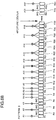
Fig. 12 is a block diagram of the ultrasonic diagnostic
apparatus (a conventional example 2) disclosed in Japanese
Laid Open Utility Model Patent Application (JP-A-Showa,
58-70208). In Fig. 12, a probe 1 is an ultrasonic probe that
includes arrayed transducer elements 2-1 to 2-128. High
voltage switches 3-1 to 3-64 are switches to select the
apertures to be used. A transmission pulse generator 4 is a
unit for generating a transmission pulse. Voltage ― current
converting amplifiers 5-1 to 64 are units for converting
voltages into currents. A cross point switch 6 is a switch for
re-arranging received signals. Current ― voltage converting
amplifiers 7-1 to 32 are units for converting currents into
voltages. A/D converters 8-1 to 8-32 are units for converting
analog received signals into digital signals. A beam former 9
is a unit for delaying and adding the data after the digital
conversion. A B-mode signal processing circuit 10 is a unit
for carrying out a signal process for a B-mode displaying. A
Doppler blood flow meter signal processing circuit 11 is a unit
for carrying out a signal process for a Doppler blood flow
meter. A color flow signal processing circuit 12 is a unit for
carrying out a signal process for a color flow. An image
synthesizer 13 is a unit for synthesizing the signals from the
respective signal processing circuits of the B-mode signal
processing circuit 10 to the color flow signal processing circuit
12 and constituting a display image. A display 14 is a unit
for displaying the synthesized image. A controller 15 is a
unit for controlling the respective units of the ultrasonic
diagnostic apparatus. An operating unit 16 is an inputting
unit that is operated by an operator.
-
The connection of the cross point switch 6 in this
conventional example 2 is shown in Fig. 13A. Numbers 1,
2, ... are assigned to the signals in the order starting from the
ends of signal receiving apertures. In the cross point switch
6, two signals adjacent to each other are connected to one
output terminal. At the former stage of the cross point
switch, a received signal is converted into a current. Since
the two signals are connected to the one output terminal, the
output to which the current of the two signals is added can be
taken out from the output terminal. Hereafter, the
connection of the cross point switch 6 is represented as shown
in Fig. 13B. In this way, the addition of the received signals
of the two transducer elements adjacent to each other enables
the drops in the input numbers of the A/D converters and
beam formers, which consequently enables the reduction in
the device amount.
-
However, even the addition for every two signals as
mentioned above may bring about a problem. In the signal at
the aperture end, the difference between the arrival times of
the signals from the transducer elements adjacent to each
other is great, which makes a delay precision poor. So, in
order to solve this problem, in a conventional example 3 in
which the conventional example 2 is improved, the addition of
the transducer elements is not uniform. This method will be
described below by using Fig. 14.
-
Fig. 14 is the connecting method of the cross point
switch in the conventional example 3. In the conventional
example 3, with the approach to the center of the aperture,
the number of the received signals to be added is increased,
and at the end, it is assumed to be 1. The fact that the
difference of the delay time is small at the center of the
aperture and the difference of the delay time is large at the
end is considered.
-
However, in the conventional ultrasonic diagnostic
apparatus, even in the above-mentioned conventional example
3, depending on the convergence condition, the difference of
the delay time between the transducer elements to be added
becomes great, which results in the problem that the
convergence precision becomes poor.
DISCLOSURE OF THE INVENTION
-
It is therefore an object of the present invention to
provide an ultrasonic diagnostic apparatus which solves those
problems and attains a sharp beam shape by using a small
quantity of receiving circuit configuration and has a high
image quality.
-
In order to solve the above-mentioned problems, in the
present invention, the ultrasonic diagnostic apparatus is
designed so as to include: a plurality of transducer elements
arrayed as an ultrasonic probe; a plurality of transmission
driving circuits for driving the transducer elements; a beam
former for delaying and adding the signals received by the
transducer elements; a cross point switch for distributing the
signals received by the transducer elements to any of a
plurality of input terminals of the beam former; and a
connection setting unit for setting the cross point switch so as
to connect by integrating the received signals of the plurality
of transducer elements near a center of an aperture of the
ultrasonic probe and inputting to one terminal of the beam
former and so as not to connect at least one of the transducer
elements at an end of the aperture to the beam former.
-
Due to the above-mentioned configuration, it is possible
to carry out the adjustment without connecting the received
signals of the transducer elements at both ends of the
aperture of the ultrasonic probe to the cross point switch, and
possible to improve the delay precision of the received signal
and consequently possible to improve the image quality.
-
Also, the connection setting unit includes: a unit for
storing two or more connection pattern data between the
transducer element and the beam former; a unit for selecting
one of the connection pattern data in accordance with a
selected display depth, transmission focus position or display
mode; and a unit for setting the cross point switch in
accordance with the selected connection pattern data. Due to
such configuration, the delay precision can be improved on the
basis of the display depth, the transmission focus position and
the display mode.
-
Also, when at the time of the transmission, the two
transducer elements adjacent to each other are driven by the
same transmission pulse generating circuit, the side lobe
direction in the transmission beam and the side lobe direction
in the received beam can be separated, thereby making the
total beam shape sharper.
BRIEF DESCRIPTION OF THE DRAWINGS
-
- Fig. 1 is an explanation view showing a method of
adding received signals by using a cross point switch, in an
ultrasonic diagnostic apparatus in a first embodiment of the
present invention;
- Fig. 2A and Fig. 2B are explanation views showing a
method of adding received signals by using a cross point
switch, in an ultrasonic diagnostic apparatus in a second
embodiment of the present invention;
- Fig. 2C is a block diagram of a control main section of
the ultrasonic diagnostic apparatus in the second embodiment
of the present invention;
- Fig. 3A and Fig. 3B are explanation views showing a
method of adding received signals by using a cross point
switch, in an ultrasonic diagnostic apparatus in a third
embodiment of the present invention;
- Fig. 3C is a block diagram of a control main section of
the ultrasonic diagnostic apparatus in the third embodiment
of the present invention;
- Fig. 4A and Fig. 4B are explanation views showing a
method of adding received signals by using a cross point
switch, in an ultrasonic diagnostic apparatus in a fourth
embodiment of the present invention;
- Fig. 4C is a block diagram of a control main section of
the ultrasonic diagnostic apparatus in the fourth embodiment
of the present invention;
- Fig. 5A and Fig. 5B are explanation views showing a
method of adding received signals by using a cross point
switch, in an ultrasonic diagnostic apparatus in a fifth
embodiment of the present invention;
- Fig. 5C is a block diagram of a control main section of
the ultrasonic diagnostic apparatus in the fifth embodiment of
the present invention;
- Fig. 6A and Fig. 6B are explanation views showing a
method of adding received signals by using a cross point
switch, in an ultrasonic diagnostic apparatus in a sixth
embodiment of the present invention;
- Fig. 6C is a block diagram of a control main section of
the ultrasonic diagnostic apparatus in the sixth embodiment
of the present invention;
- Fig. 7 is a block diagram of a control main section of
the ultrasonic diagnostic apparatus in the seventh
embodiment of the present invention;
- Fig. 8 is a block diagram of a control main section of
the ultrasonic diagnostic apparatus in the eighth embodiment
of the present invention;
- Fig. 9A is an explanation view showing a method of
adding received signals by using a cross point switch, in an
ultrasonic diagnostic apparatus in a ninth embodiment of the
present invention;
- Fig. 9B is an explanation view showing a weighting in
the ultrasonic diagnostic apparatus in the ninth embodiment
of the present invention;
- Fig. 10A is an explanation view showing a beam shape
of a transmission of an ultrasonic diagnostic apparatus in a
tenth embodiment of the present invention;
- Fig. 10B is an explanation view showing a received
beam shape of the ultrasonic diagnostic apparatus in the
tenth embodiment of the present invention;
- Fig. 10C is a block diagram of a transmitting circuit
main section of the ultrasonic diagnostic apparatus in the
tenth embodiment of the present invention;
- Fig. 11 is a block diagram of an ultrasonic diagnostic
apparatus (a conventional example 1) for carrying out a
conventional sector scan;
- Fig. 12 is a block diagram of an ultrasonic diagnostic
apparatus (a conventional example 2) for carrying out a
conventional sector scan;
- Fig. 13A and Fig. 13B are explanation views showing a
method of adding received signals by using a cross point
switch, in the ultrasonic diagnostic apparatus (the
conventional example 2) for carrying out the conventional
sector scan.
- Fig. 14 is an explanation view showing a method of
adding received signals by using a cross point switch, in an
ultrasonic diagnostic apparatus (a conventional example 3) for
carrying out the conventional sector scan.
-
BEST MODE FOR CARRYING OUT THE INVENTION
-
Embodiments of the present invention will be described
below in detail with reference to Fig. 1 to Fig. 10
<First Embodiment>
-
The first embodiment of the present invention is the
ultrasonic diagnostic apparatus, in which a cross point switch
is set such that near the center of an aperture of an
ultrasonic probe, received signals from 3 transducer elements
are integrated into one and inputted to one terminal of a
beam former, and at both ends of the aperture, 3 transducer
elements which are placed every other transducer element are
not connected to the beam former.
-
Fig. 1 is an explanation view showing a method of
adding the received signals by using the cross point switch, in
the ultrasonic diagnostic apparatus in the first embodiment of
the present invention. In Fig. 1, received signals R1 to R64
are the received signals from the transducer elements selected
by high voltage switches, among the ultrasonic transducer
elements arrayed in an ultrasonic probe to transmit and
receive ultrasonic. Addition signals A1 to A32 are the
signals as the results after the received signals are added by
the cross point switch. The basic configuration of the
ultrasonic diagnostic apparatus is equal to the conventional
example 2 shown in Fig. 12.
-
The operations of the ultrasonic diagnostic apparatus
in the first embodiment of the present invention configured as
mentioned above will be described below. In order to
determine the position, shape and the like of the aperture to
be used as the ultrasonic probe, the high voltage switches are
used to select 64 transducer elements from 128 transducer
elements. The received signals from the selected transducer
elements are indicated as the received signals R1 to R64.
That is, they are indicated under the assumption that the
transducer elements are arrayed in the manner of 2-1, 2-2, ...,
2-64 from the left end of the aperture. The center of the
aperture is located between the 32-th transducer element and
the 33-th transducer element. The second, fourth, sixth,
59-th, 61-th and 63-th transducer elements at both ends are
not used. Those received signals are added, as shown in Fig.
1, by the cross point switch, and defined as the addition
signals A1 to A32. The processes on and after the processes
in which the addition signals A1 to A32 are converted into the
voltages by the current ― voltage converting amplifiers, and
converted into the digital signals by the A/D converters, and
then delay-added by the beam former are equal to the
conventional example 2.
-
In the transducer elements near the aperture center,
the number of the transducer elements to be added is reduced
from 4 to 3. At both the ends of the aperture, a total of 6
non-connected transducer elements are set every other
transducer element. As compared with the conventional
example 3 shown in Fig. 14, the number of the signals after
the addition is equal, and the circuit amount of the signal
process is not increased. The number of the signals at both
the ends of the aperture in which the difference between the
delay times of the received ultrasonic signals is great is
decreased, and the number of the signals at the center of the
aperture in which the difference between the delay times of
the received ultrasonic signals is small is increased. Thus,
the delay property of the received ultrasonic can be improved,
thereby make the shape of the received ultrasonic beam
sharper.
-
As mentioned above, in the first embodiment of the
present invention, in the ultrasonic diagnostic apparatus, the
cross point switch is set such that near the center of the
aperture of the ultrasonic probe, the received signals from the
3 transducer elements are integrated into one and inputted to
the one terminal of the beam former, and at both the ends of
the aperture, the 3 transducer elements which are placed
every other transducer element are not connected to the beam
former. Thus, the delay property of the received ultrasonic is
improved, and the beam shape is made sharper.
<Second Embodiment>
-
The second embodiment of the present invention is the
ultrasonic diagnostic apparatus, which prepares two
connection pattern data between the transducer element and
the beam former, and selects the connection pattern data in
accordance with a display depth, and then sets the cross point
switch.
-
Fig. 2A, Fig. 2B and Fig. 2C are explanation views
showing a method of adding the received signals, in the
ultrasonic diagnostic apparatus in the second embodiment of
the present invention. Fig. 2A is a pattern A using a first
adding method. Fig. 2B is a pattern B using a second adding
method. The meanings of the symbols in Fig. 2A and Fig. 2B
are equal to Fig. 1. Fig. 2C is a block diagram showing an
operating unit, a controller and the cross point switch in
detail. In Fig. 2C, a cross point switch 6 is a switch to
re-arrange the received signals. A controller 15 is a unit for
controlling the respective units of the ultrasonic diagnostic
apparatus. A cross point switch connection memory 15-1 is a
memory for storing the connection pattern data. The
operating unit 16 is the inputting unit which is operated by
an operator. A display depth selecting switch 16-1 is a
switch to select the display depth desired by the operator.
The other basic configurations of the ultrasonic diagnostic
apparatus are equal to the conventional example 2 shown in
Fig. 12.
-
The operations of the ultrasonic diagnostic apparatus
in the second embodiment of the present invention configured
as mentioned above will be described below. As the patterns
of the method in which the received signals are added by the
cross point switch, the pattern A shown in Fig. 2A and the
pattern B shown in Fig. 2B are prepared. The pattern A has
more transducer elements which are not used at the end, and
it is suitable for the reception in a relatively shallow portion.
If three or more patterns are prepared, it is possible to cope
with the desired depth in detail.
-
As shown in Fig. 2C, the display depth selecting switch
16-1 is placed in the operating unit 16. The cross point
switch connection memory 15-1 is placed in the controller 15.
When the operator operates the display depth selecting switch
16-1 and a display depth change command is inputted to the
controller 15, the pattern data corresponding to the display
depth is read from the cross point switch connection memory
15-1. The read pattern data is transmitted, as the
information to change the connection of the cross point switch,
to the cross point switch 6, and the connection of the cross
point switch 6 is changed.
-
The received signals are added by the cross point
switch in accordance with the changed connection and defined
as the addition signals A1 to A32. The processes on and
after the processes in which the addition signals A1 to A32
are converted into the voltages by the current ― voltage
converting amplifiers, and converted into the digital signals
by the A/D converters, and then delay-added by the beam
former are equal to the conventional example 2.
-
If the operator desires the displaying of the shallow
depth, the display depth selecting switch 16-1 is used to
select the shallow depth. The display depth change command
is outputted from the operating unit 16, and the data of the
pattern A corresponding to the shallow depth is read from the
cross point switch connection memory 15-1 of the controller 15.
The connection of the cross point switch 6 is changed in
accordance with the data of the pattern A. The received
signals are added by the cross point switch in accordance with
the changed connection, and delay-added by the beam former,
and a predetermined operating process is performed. Then,
it is displayed as a picture. If the operator desires the deep
depth, the connection of the cross point switch 6 is changed in
accordance with the data of the pattern B, and the picture
having the high precision of the deep depth is displayed.
-
As mentioned above, in the second embodiment of the
present invention, the ultrasonic diagnostic apparatus is
designed such that the two connection pattern data between
the transducer element and the beam former are prepared,
and the connection pattern data is selected in accordance with
the display depth, and the cross point switch is set. Thus,
correspondingly to the display depth, the pattern of the
adding method of the received signals can be changed, thereby
obtaining the optimal image.
<Third Embodiment>
-
The third embodiment of the present invention is the
ultrasonic diagnostic apparatus, which prepares the two
connection pattern data between the transducer element and
the beam former, and selects the connection pattern data in
accordance with a selected transmission focus position, and
then sets the cross point switch.
-
Fig. 3A, Fig. 3B and Fig. 3C are explanation views
showing a method of adding the received signals, in the
ultrasonic diagnostic apparatus in the third embodiment of
the present invention. Fig. 3A is the pattern A using the
first adding method. Fig. 3B is the pattern B using the
second adding method. The meanings of the symbols in Fig.
3A and Fig. 3B are equal to Fig. 1. Fig. 3C is a block
diagram showing the operating unit, the controller and the
cross point switch in detail. In Fig. 3C, the cross point
switch 6 is the switch to re-arrange the received signals.
The controller 15 is the unit for controlling the respective
units of the ultrasonic diagnostic apparatus. The cross point
switch connection memory 15-1 is the memory for storing the
connection pattern data. The operating unit 16 is the
inputting unit which is operated by the operator. A
transmission focus selecting switch 16-2 is a switch to select
an adding method pattern of the received signals on the basis
of a transmission focus depth. The other basic configurations
of the ultrasonic diagnostic apparatus are equal to the
conventional example 2 shown in Fig. 12.
-
The operations of the ultrasonic diagnostic apparatus
in the third embodiment of the present invention configured
as mentioned above will be described below. As the patterns
of the method in which the received signals are added by the
cross point switch, the pattern A shown in Fig. 3A and the
pattern B shown in Fig. 3B are prepared. Since the pattern
A has the more transducer elements which are not used at the
end, the beam shape when the aperture is small at the
relatively shallow portion is excellent. If three or more
patterns are prepared, it is possible to cope with the
transmission focus depth in detail.
-
As shown in Fig. 3C, the transmission focus selecting
switch 16-2 is placed in the operating unit 16. The cross
point switch connection memory 15-1 is placed in the
controller 15. When the operator operates the transmission
focus selecting switch 16-2 and a transmission focus depth
change command is inputted to the controller 15, a read
content of the cross point switch connection memory 15-1 is
changed. The information to change the connection of the
cross point switch is transmitted to the cross point switch 6,
and the connection of the cross point switch 6 is changed.
-
The received signals are added by the cross point
switch in accordance with the changed connection and defined
as the addition signals A1 to A32. The processes on and
after the processes in which the addition signals A1 to A32
are converted into the voltages by the current ― voltage
converting amplifiers, and converted into the digital signals
by the A/D converters, and then delay-added by the beam
former are equal to the conventional example 2.
-
If the transmission focus is located at a shallow portion,
the beam shape of the shallow portion is excellent. Thus,
when the receiving beam is considered totally with regard to
the transmission/reception, even if the shallow portion has
many side lobes, the side lobes become few. Reversely, if the
transmission focus is deep, the transmission focus is not
excellent at the shallow portion. Hence, it is necessary to
improve the shape of the receiving beam and prevent the
deterioration in the beam shape of the transmission/reception.
-
If the transmission focus is located at a deep portion,
the transmission focus selecting switch 16-2 is used to select
the deep transmission focus depth. The transmission focus
depth change command is outputted from the operating unit
16, and the data of the pattern A corresponding to the deep
transmission focus depth is read from the cross point switch
connection memory 15-1 of the controller 15. The connection
of the cross point switch 6 is changed in accordance with the
data of the pattern A. The received signals are added by the
cross point switch in accordance with the changed connection,
and delay-added by the beam former, and a predetermined
operating process is performed. Then, it is displayed as a
picture. If the operator selects the shallow transmission
focus depth, the connection of the cross point switch 6 is
changed in accordance with the data of the pattern B, and the
picture having the high precision as a whole is displayed.
-
As mentioned above, in the third embodiment of the
present invention, the ultrasonic diagnostic apparatus is
designed such that the two connection pattern data between
the transducer element and the beam former are prepared,
and the connection pattern data is selected in accordance with
the selected transmission focus position, and the cross point
switch is set. Thus, correspondingly to the transmission
focus depth, the pattern of the adding method of the received
signals can be changed, thereby obtaining the optimal image
as a whole.
<Fourth Embodiment>
-
The fourth embodiment of the present invention is the
ultrasonic diagnostic apparatus, which prepares the two
connection pattern data between the transducer element and
the beam former, and selects the connection pattern data in
accordance with a selected display mode, and then sets the
cross point switch.
-
Fig. 4A, Fig. 4B and Fig. 4C are explanation views
showing a method of adding the received signals, in the
ultrasonic diagnostic apparatus in the fourth embodiment of
the present invention. Fig. 4A is the pattern A using the
first adding method. Fig. 4B is the pattern B using the
second adding method. The meanings of the symbols in Fig.
4A and Fig. 4B are equal to Fig. 1. Fig. 4C is a block
diagram showing the operating unit, the controller and the
cross point switch in detail. In Fig. 4C, the cross point
switch 6 is the switch to re-arrange the received signals.
The controller 15 is the unit for controlling the respective
units of the ultrasonic diagnostic apparatus. The cross point
switch connection memory 15-1 is the memory for storing the
connection pattern data. The operating unit 16 is the
inputting unit which is operated by the operator. A mode
selecting switch 16-3 is a switch to select an adding method
pattern of the received signals on the basis of the display
mode. The other basic configurations of the ultrasonic
diagnostic apparatus are equal to the conventional example 2
shown in Fig. 12.
-
The operations of the ultrasonic diagnostic apparatus
in the fourth embodiment of the present invention configured
as mentioned above will be described below. As the patterns
of the method in which the received signals are added by the
cross point switch, the pattern A shown in Fig. 4A and the
pattern B shown in Fig. 4B are prepared. The pattern A has
the fewer side lobes when the aperture is fully used, and the
omission of an image is excellent. On the other hand, the
pattern B has the fewer transducer elements which are not
used at the end, and it is advantageous with respect to the
sensibility. Thus, at a B-mode in which the excellent
omission is required, the usage of the pattern A is preferable.
At the Doppler blood flow meter mode and color flow mode in
which the sensibility is required, the usage of the pattern B is
preferable. If three or more patterns are prepared, it is
possible to cope with the various modes in detail.
-
As shown in Fig. 4C, the mode selecting switch 16-3 is
placed in the operating unit 16. The cross point switch
connection memory 15-1 is placed in the controller 15. When
the operator operates the mode selecting switch 16-3 and a
mode change command is inputted to the controller 15, the
read content of the cross point switch connection memory is
changed. The information to change the connection of the
cross point switch is transmitted to the cross point switch 6,
and the connection of the cross point switch 6 is changed.
-
The received signals are added by the cross point
switch in accordance with the changed connection and defined
as the addition signals A1 to A32. The processes on and
after the processes in which the addition signals A1 to A32
are converted into the voltages by the current ― voltage
converting amplifiers, and converted into the digital signals
by the A/D converters, and then delay-added by the beam
former are equal to the conventional example 2.
-
If the operator desires the displaying of the B-mode,
the mode selecting switch 16-1 is used to select the B-mode.
The mode change command is outputted from the operating
unit 16, and the data of the pattern A corresponding to the
B-mode is read from the cross point switch connection memory
15-1 of the controller 15. The connection of the cross point
switch 6 is changed in accordance with the data of the pattern
A. The received signals are added by the cross point switch
in accordance with the changed connection, and delay-added
by the beam former, and a predetermined operating process is
performed. Then, it is displayed as a picture. If the
operator selects the Doppler blood flow meter mode and the
color flow mode, the connection of the cross point switch 6 is
changed in accordance with the data of the pattern B, and the
picture having the high precision is displayed.
-
As mentioned above, in the fourth embodiment of the
present invention, the ultrasonic diagnostic apparatus is
designed such that the two connection pattern data between
the transducer element and the beam former are prepared,
and the connection pattern data is selected in accordance with
the selected display mode, and the cross point switch is set.
Thus, it is possible to select the pattern of the adding method
which corresponds to each of the signal processing modes, and
possible to obtain the optimal image.
<Fifth Embodiment>
-
The fifth embodiment of the present invention is the
ultrasonic diagnostic apparatus, which prepares the two
connection pattern data between the transducer element and
the beam former, and selects the connection pattern data in
accordance with the priority of a selected main/side lobe, and
then sets the cross point switch.
-
Fig. 5A, Fig. 5B and Fig. 5C are explanation views
showing a method of adding the received signals, in the
ultrasonic diagnostic apparatus in the fifth embodiment of the
present invention. Fig. 5A is the pattern A using the first
adding method. Fig. 5B is the pattern B using the second
adding method. The meanings of the symbols in Fig. 5A and
Fig. 5B are equal to Fig. 1. Fig. 5C is a block diagram
showing the operating unit, the controller and the cross point
switch in detail. In Fig. 5C, the cross point switch 6 is the
switch to re-arrange the received signals. The controller 15
is the unit for controlling the respective units of the
ultrasonic diagnostic apparatus. The cross point switch
connection memory 15-1 is the memory for storing the
connection pattern data. The operating unit 16 is the
inputting unit which is operated by the operator. A
main/side lobe priority selecting switch 16-4 is a switch to
select an adding method pattern of the received signals on the
basis of the side lobe to which the priority is assigned. The
other basic configurations of the ultrasonic diagnostic
apparatus are equal to the conventional example 2 shown in
Fig. 12.
-
The operations of the ultrasonic diagnostic apparatus
in the fifth embodiment of the present invention configured as
mentioned above will be described below. As the patterns of
the method in which the received signals are added by the
cross point switch, the pattern A shown in Fig. 5A and the
pattern B shown in Fig. 5B are prepared. The pattern A has
the fewer side lobes when the aperture is fully used, and the
omission of the image is excellent. On the other hand, the
pattern B has the fewer transducer elements which are not
used at the end, and the main lobe is slim. Thus, in
accordance with the wish of the operator, it is possible to
carry out the proper usage selection, such as the selection of
the pattern A if the excellent omission is desired or the
selection of the pattern B if the excellent resolution is desired.
If three or more patterns are prepared, it is possible to cope
with the request of the image quality in detail.
-
As shown in Fig. 5C, the main/side lobe priority
selecting switch 16-4 is placed in the operating unit 16. The
cross point switch connection memory 15-1 is placed in the
controller 15. When the operator operates the main/side lobe
priority selecting switch 16-4 and a priority mode set
command is inputted to the controller 15, the read content of
the cross point switch connection memory is changed. The
information to change the connection of the cross point switch
is transmitted to the cross point switch 6, and the connection
of the cross point switch 6 is changed.
-
The received signals are added by the cross point
switch in accordance with the changed connection and defined
as the addition signals A1 to A32. The processes on and
after the processes in which the addition signals A1 to A32
are converted into the voltages by the current ― voltage
converting amplifiers, and converted into the digital signals
by the A/D converters, and then delay-added by the beam
former are equal to the conventional example 2.
-
If the operator desires the displaying of the excellent
omission, the mode selecting switch 16-1 is used to select the
side lobe priority. The priority mode set command is
outputted from the operating unit 16, and the data of the
pattern A corresponding to the side lobe priority is read from
the cross point switch connection memory 15-1 of the
controller 15. The connection of the cross point switch 6 is
changed in accordance with the data of the pattern A. The
received signals are added by the cross point switch in
accordance with the changed connection, and delay-added by
the beam former, and a predetermined operating process is
performed. Then, it is displayed as a picture. If the
operator desires the displaying of the excellent resolution,
when the main lobe priority is selected, the connection of the
cross point switch 6 is changed in accordance with the data of
the pattern B, and the picture having the high resolution is
displayed.
-
As mentioned above, in the fifth embodiment of the
present invention, the ultrasonic diagnostic apparatus is
designed such that the two connection pattern data between
the transducer element and the beam former are prepared,
and the connection pattern data is selected in accordance with
the priority of the selected main/side lobe, and the cross point
switch is set. Thus, it is possible to select the pattern of the
adding method of the received signals, on the basis of the
image quality along the wish of the operator, and possible to
obtain the optimal image.
<Sixth Embodiment>
-
The sixth embodiment of the present invention is the
ultrasonic diagnostic apparatus, which prepares the two
connection pattern data between the transducer element and
the beam former, and while switching the transmission focus
position, repeats the transmission/reception in the same
direction a plurality of times, and when extracting and
synthesizing the images of shallow portion and deep portion,
selects the connection pattern data in accordance with a
shallow portion image extraction sequence or deep portion
image extraction sequence, and then sets the cross point
switch.
-
Fig. 6A, Fig. 6B and Fig. 6C are explanation views
showing a method of adding the received signals, in the
ultrasonic diagnostic apparatus in the sixth embodiment of
the present invention. Fig. 6A is the pattern A using the
first adding method. Fig. 6B is the pattern B using the
second adding method. The meanings of the symbols in Fig.
6A and Fig. 6B are equal to Fig. 1. Fig. 6C is a view showing
the timings of the sequences.
-
The operations of the ultrasonic diagnostic apparatus
in the sixth embodiment of the present invention configured
as mentioned above will be described below. As the patterns
of the method in which the received signals are added by the
cross point switch, the pattern A shown in Fig. 6A and the
pattern B shown in Fig. 6B are prepared. Since the pattern
A has the more transducer elements which are not used at the
end, the beam shape when the aperture is small at the
relatively shallow portion is excellent. On the other hand,
since the pattern B has the fewer transducer elements which
are not used at the end and has the excellent sensibility, it is
suited to view the deep portion. If three or more patterns
are prepared, it is possible to cope with the various sequences
in detail.
-
In the ultrasonic diagnostic apparatus, there is a
function of changing the transmission focus in the same
direction, carrying out the transmission/reception a plurality
of times, and synthesizing the images and consequently
obtaining the image with the excellent resolution from the
shallow portion to the deep portion. In this function, by
switching between the usage of the pattern A in the signal
obtaining sequence for the shallow portion and the usage of
the pattern B in the signal obtaining sequence for the deep
portion, it is possible to consequently obtain the excellent
image in any one of both the depths.
-
As shown in the timing chart of the sequence in Fig. 6C,
in the sequence at which the transmission focus is shallow,
the connection of the cross point switch is set at the pattern A,
and the image data of the shallow portion is obtained. In the
sequence at which the transmission focus is deep, the
connection of the cross point switch is set at the pattern B,
and the image data of the deep portion is obtained.
Consequently, it is possible to obtain the picture having the
excellent image quality from the shallow portion to the deep
portion.
-
As mentioned above, in the sixth embodiment of the
present invention, the ultrasonic diagnostic apparatus is
designed such that the two connection pattern data between
the transducer element and the beam former are prepared,
and when while the transmission focus position is switched,
the transmission/reception is repeated in the same direction
the plurality of times, and the images of the shallow portion
and deep portion are extracted and synthesized, the
connection pattern data is selected in accordance with the
shallow portion image extraction sequence or deep portion
image extraction sequence, and the cross point switch is set.
Thus, it is possible to obtain the optimal image as a whole.
<Seventh Embodiment>
-
The seventh embodiment of the present invention is the
ultrasonic diagnostic apparatus for changing the size of the
aperture of the probe and the like, on the basis of the display
depth.
-
Fig. 7 is a block diagram of the control main section of
the ultrasonic diagnostic apparatus in the seventh
embodiment of the present invention. In Fig. 7, the beam
former 9 is the unit for delaying and adding the received data
which is digitally converted. An aperture controller 9-1 is a
unit for changing the addition pattern of the received signals
in the beam former and consequently changing the size of the
aperture of the probe and the like. The controller 15 is the
unit for controlling the respective units of the ultrasonic
diagnostic apparatus. An aperture control data generator
15-2 is a unit for generating the addition pattern of the
received signals in the beam former, on the basis of a
specified aperture condition. The operating unit 16 is the
inputting unit that is operated by the operator. The display
depth selecting switch 16-1 is the switch for the operator to
select the desirable display depth. The other basic
configurations of the ultrasonic diagnostic apparatus are
equal to the conventional example 2 shown in Fig. 12.
-
The operations of the ultrasonic diagnostic apparatus
in the seventh of the present invention configured as
mentioned above will be described below. In the setting of
the cross point switch as explained in the first embodiment,
by changing the aperture conditions such as the size of the
aperture of the probe and the like, it is possible to cope with
the cases that the display portions are shallow and deep.
-
When the operator uses the display depth selecting
switch 16-1 contained in the operating unit 16 to change the
display depth, the display depth change command is inputted
to the controller 15. In accordance with the display depth
change command, the aperture control data generator 15-2 of
the controller 15 generates the data to attain the aperture
condition corresponding to the specified change command.
That is, so as to satisfy the aperture condition corresponding
to the specified display depth, it generates the pattern data
for the beam former to add the received signals. The
aperture controller 9-1 sets the generated pattern data for the
beam former 9, and consequently controls the aperture of the
probe.
-
For example, if the display depth is shallow, the
aperture of the probe is set to be slightly small, thereby
suppressing the side lobe caused by the error of the delay
time at the end of the aperture. In this way, it is possible to
carry out the aperture control corresponding to the display
depth, and possible to obtain the picture of the excellent
image quality, independently of the display depth.
-
As mentioned above, in the seventh embodiment of the
present invention, the ultrasonic diagnostic apparatus is
designed so as to change the size of the aperture of the probe
and the like, correspondingly to the display depth. Thus, it
is possible to obtain the optimal image over the entire depth.
<Eighth Embodiment>
-
The eighth embodiment of the present invention is the
ultrasonic diagnostic apparatus for changing the size of the
aperture of the probe and the like, on the basis of the
transmission focus position.
-
Fig. 8 is a block diagram of the control main section of
the ultrasonic diagnostic apparatus in the eighth embodiment
of the present invention. In Fig. 8, the beam former 9 is the
unit for delaying and adding the received data which are
digitally converted. The aperture controller 9-1 is the unit
for changing the addition pattern of the received signals in
the beam former and consequently changing the size of the
aperture of the probe and the like. The controller 15 is the
unit for controlling the respective units of the ultrasonic
diagnostic apparatus. The aperture control data generator
15-2 is the unit for generating the addition pattern of the
received signals in the beam former, on the basis of the
specified aperture condition. The operating unit 16 is the
inputting unit that is operated by the operator. The
transmission focus selecting switch 16-2 is the switch to
select the adding method pattern of the received signals on
the basis of the transmission focus depth. The other basic
configurations of the ultrasonic diagnostic apparatus are
equal to the conventional example 2 shown in Fig. 12.
-
The operations of the ultrasonic diagnostic apparatus
in the eighth of the present invention configured as
mentioned above will be described below. In the setting of
the cross point switch as explained in the first embodiment,
by changing the aperture conditions such as the size of the
aperture of the probe and the like, it is possible to cope with
the cases that the transmission focus positions are shallow
and deep.
-
When the operator uses the transmission focus
selecting switch 16-2 contained in the operating unit 16 to
change the transmission focus depth, the transmission focus
depth change command is inputted to the controller 15. In
accordance with the transmission focus depth change
command, the aperture control data generator 15-2 of the
controller 15 generates the data to attain the aperture
condition corresponding to the specified transmission focus
depth. That is, so as to satisfy the aperture condition
corresponding to the specified transmission focus depth, it
generates the pattern data for the beam former to add the
received signals. The aperture controller 9-1 sets the
generated pattern data for the beam former 9, and
consequently controls the aperture of the probe.
-
For example, if the focus position is deep, the aperture
of the probe is set to be slightly small, thereby suppressing
the side lobe caused by the error of the delay time at the end
of the aperture. In this way, it is possible to carry out the
aperture control corresponding to the transmission focus
depth, and possible to obtain the picture of the excellent
image quality, independently of the transmission focus
position.
-
As mentioned above, in the eighth embodiment of the
present invention, the ultrasonic diagnostic apparatus is
designed so as to change the size of the aperture of the probe
and the like, correspondingly to the transmission focus
position. Thus, it is possible to obtain the optimal image
over the entire depth of the transmission focus.
<Ninth Embodiment>
-
The ninth embodiment of the present invention is the
ultrasonic diagnostic apparatus, in which the amplification
factor of the received signals remaining in the part after the
received signals are removed at both the ends of the aperture
of the probe is increased.
-
Fig. 9A and Fig. 9B are an explanation view showing a
method of adding the received signals by using the cross point
switch and an explanation view showing a weighting,
respectively in the ultrasonic diagnostic apparatus in the
ninth embodiment of the present invention. Fig. 9A is a
setting view of the cross point switch indicating the adding
method of the received signals. The meanings of the symbols
in Fig. 9A are equal to Fig. 1. Fig. 9B is a graph showing the
relation between an aperture position and an amplification
gain.
-
The operations of the ultrasonic diagnostic apparatus
in the ninth embodiment of the present invention configured
as mentioned above will be described below. In the setting of
the cross point switch explained in the first embodiment, the
unused transducer elements exist at both the ends of the
aperture of the probe, which cause the drop in the sensibility
of the end. In order to compensate it, the amplification gain
of the signal of the end is increased. Consequently, the
excellent beam shape can be attained.
-
As indicated in the graph of the aperture position and
amplification gain shown in Fig. 9B, at both the ends of the
aperture of the probe, as the frequency of the unused
transducer elements is increased, the gain is made higher,
and the amplification gain is made lower, at the portion in
which all transducer elements in the central portion are used.
Consequently, the beam shape can be made sharper, thereby
obtaining the picture of the excellent image quality.
-
As mentioned above, in the ninth embodiment of the
present invention, the ultrasonic diagnostic apparatus is
designed such that the amplification factor of the received
signals remaining in the part after the received signals are
removed at both the ends of the aperture of the probe is
increased. Thus, the beam shape of the received signal can
be made sharper.
<Tenth Embodiment>
-
The tenth embodiment of the present invention is the
ultrasonic diagnostic apparatus, in which in order to separate
between the peak position of the side lobe of a transmission
beam and the peak position of the side lobe of a received beam,
at a time of transmission, two channels adjacent to each other
are driven by the same driving circuit.
-
Fig. 10A, Fig. 10B and Fig. 10C are explanation views
showing the beam shapes of transmission and reception and a
block diagram of a transmitting circuit main section,
respectively, in the ultrasonic diagnostic apparatus in the
tenth embodiment of the present invention. Fig. 10A is a
graph showing the shape of the transmission beam. Fig. 10B
is a graph showing the shape of the received beam. Fig. 10C
is a block diagram of the transmitting circuit main section.
In Fig. 10C, a transmission pulse generator 4 is a unit for
generating a transmission pulse. A timing generating circuit
4-1 is a circuit for controlling the generation timing of the
transmission pulse. A pulse driver 4-2 is a circuit for
power-amplifying the transmission pulse and vibrating the
transducer element. Diodes 4-3a and 4-3b are backflow
protecting devices for applying drive pulses to the transducer
elements. The other basic configurations of the ultrasonic
diagnostic apparatus are equal to the conventional example 2
shown in Fig. 12.
-
The operations of the ultrasonic diagnostic apparatus
in the tenth embodiment of the present invention configured
as mentioned above will be described below. As disclosed in
Japanese Laid Open Patent Application (JP-A 2000-152937), a
method is known in which transducer elements adjacent to
each other are driven by the same transmission pulse
generator. In this method, since the two transducer
elements adjacent to each other are driven by one
transmission pulse generator, the beam shape is indicated by
the graph shown in Fig. 10A. On the contrary, in the setting
of the cross point switch explained in the first embodiment,
the beam shape is indicated by the graph shown in Fig. 10B,
and the positions of the side lobes are different.
-
This fact can be used to reduce the side lobe in the
received signal. At the time of the transmission, the circuit
shown in Fig. 10C is used to drive the transducer elements,
two at a time. At the time of the reception, the connecting
method of the cross point switch explained in the first
embodiment is used to process the received signal. By
making the positions of the side lobes different between the
transmission and the reception, as the total result of the
transmission and reception, the excellent beam shape in
which the side lobes are few can be attained. Consequently,
while the device amount in the transmitting/receiving circuit
is reduced, the picture with the excellent image quality can be
obtained.
-
As mentioned above, in the tenth embodiment of the
present invention, the ultrasonic diagnostic apparatus is
designed such that in order to separate between the peak
position of the side lobe in the transmission beam and the
peak position of the side lobe in the received beam, at the
time of the transmission, the two channels adjacent to each
other are driven by the same driving circuit. Thus, it is
possible to obtain the received signal in which the side lobes
are few.
INDUSTRIAL APPLICABILITY
-
As can be understood from the above-mentioned
explanations, in the present invention, the ultrasonic
diagnostic apparatus is designed so as to include: the
plurality of transducer elements arrayed as the ultrasonic
probe; the plurality of transmission driving circuits for
driving the transducer elements; the beam former for delaying
and adding the signals received by the transducer elements;
the cross point switch for distributing the signals received by
the transducer elements to any of the plurality of input
terminals of the beam former; and the connection setting unit
for setting the cross point switch so as to connect by
integrating the received signals of the plurality of transducer
elements near the center of the aperture of the ultrasonic
probe and inputting to one terminal of the beam former and so
as not to connect at least one of the transducer elements at
the end of the aperture to the beam former. Thus, it is
possible to improve the delay precision of the received
ultrasonic signals, and possible to make the beam shape
sharper, and consequently possible to obtain the effect of
enabling the improvement of the image quality of the
ultrasonic image.