EP1480397A2 - Extensions to the spanning tree protocol - Google Patents
Extensions to the spanning tree protocol Download PDFInfo
- Publication number
- EP1480397A2 EP1480397A2 EP04300238A EP04300238A EP1480397A2 EP 1480397 A2 EP1480397 A2 EP 1480397A2 EP 04300238 A EP04300238 A EP 04300238A EP 04300238 A EP04300238 A EP 04300238A EP 1480397 A2 EP1480397 A2 EP 1480397A2
- Authority
- EP
- European Patent Office
- Prior art keywords
- bridge
- core
- virtual
- participating
- root
- Prior art date
- Legal status (The legal status is an assumption and is not a legal conclusion. Google has not performed a legal analysis and makes no representation as to the accuracy of the status listed.)
- Granted
Links
Images


Classifications
-
- H—ELECTRICITY
- H04—ELECTRIC COMMUNICATION TECHNIQUE
- H04L—TRANSMISSION OF DIGITAL INFORMATION, e.g. TELEGRAPHIC COMMUNICATION
- H04L45/00—Routing or path finding of packets in data switching networks
- H04L45/48—Routing tree calculation
-
- H—ELECTRICITY
- H04—ELECTRIC COMMUNICATION TECHNIQUE
- H04L—TRANSMISSION OF DIGITAL INFORMATION, e.g. TELEGRAPHIC COMMUNICATION
- H04L12/00—Data switching networks
- H04L12/54—Store-and-forward switching systems
- H04L12/56—Packet switching systems
-
- H—ELECTRICITY
- H04—ELECTRIC COMMUNICATION TECHNIQUE
- H04L—TRANSMISSION OF DIGITAL INFORMATION, e.g. TELEGRAPHIC COMMUNICATION
- H04L45/00—Routing or path finding of packets in data switching networks
- H04L45/18—Loop-free operations
-
- H—ELECTRICITY
- H04—ELECTRIC COMMUNICATION TECHNIQUE
- H04L—TRANSMISSION OF DIGITAL INFORMATION, e.g. TELEGRAPHIC COMMUNICATION
- H04L45/00—Routing or path finding of packets in data switching networks
- H04L45/48—Routing tree calculation
- H04L45/488—Routing tree calculation using root node determination
Definitions
- the present invention relates generally to networks. More specifically, extensions to the spanning tree protocol (STP) are disclosed.
- STP spanning tree protocol
- STP Spanning Tree network protocol
- the spanning tree protocol may yield undesirable results, such as blocking all of the paths that provide connectivity between a subset of provider edge (PE) devices participating in a particular service, e.g., a transparent LAN service (TLS).
- PE provider edge
- TLS transparent LAN service
- each service may be associated with one or more customer networks, each of which may and probably will be running an instance of the STP (or a similar protocol for preventing loops).
- STP or a similar protocol for preventing loops.
- not every implementation of the STP or similar protocol will be the same. Therefore, there is a need for a way for an instance of the STP running on a core provider network to interact with instances of STP (or similar protocols) running on customer networks connected to the provider's core network.
- the invention can be implemented in numerous ways, including as a process, an apparatus, a system, a composition of matter, a computer readable medium such as a computer readable storage medium or a computer network wherein program instructions are sent over optical or electronic communication links.
- these implementations, or any other form that the invention may take, may be referred to as techniques.
- the order of the steps of disclosed processes may be altered within the scope of the invention.
- a virtual core bridge that represents the network core is simulated. It is ensured that the virtual core bridge becomes and remains the root bridge.
- the root bridge priority associated with the VCB is zero, ensuring that it becomes the root bridge.
- a validity check is done on bridge protocol data units (BPDU's) received at a provider edge device from outside the core network to ensure that the VCB will remain the root bridge.
- BPDU's bridge protocol data units
- Learning to communicate with an instance of the STP (or similar protocol) running on an external (e.g., customer) network connected to the core network is disclosed. The version/type of the STP instance running on the external network is detected, and the core network STP uses the format appropriate to the version/type of STP running on the external network to exchange STP-related data with the external network.
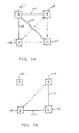
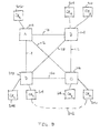
- FIG. 1A shows an exemplary network in which the spanning tree protocol may be employed.
- a core provider network 100 comprises four provider edge (PE) devices A-D, labeled 102, 104, 106, and 108, respectively, in Figure 1A.
- PE's 102-108 are connected in a full mesh by mesh connections 110-120. While connections 110-120 comprise mesh connections in a core provider network in this example, the principles described in connection with Figures 1A and 1B apply as well to other types of networks having other types of connection.
- the full mesh of connections 110-120 makes available to each of the PE's 102-108 multiple possible paths to each other node, providing a high degree of redundancy.
- PE 102 can reach PE 104 either via the direct path of connection 110 or indirectly through PE 106, e.g., via the path comprising connection 112, PE 106, and connection 116.
- this configuration also creates the possibility of loops in the network, whereby the same data packet, frame, or other unit of data could arrive at a node (e.g., one of the PE's) via multiple paths, forwarded by more than one other node, resulting in inefficiency and potentially confusion.
- This risk is present particularly when the communications protocols being used do not result in a data frame "timing out" after a prescribed period, as is the case with, for example, layer 2 LAN protocols.
- PE 106 e.g., might forward the frame on to PE's 104 and 108 (e.g., if the destination address were not known to PE 106), one of which might further forward the frame back to PE 102.
- the spanning tree protocol eliminates such loops by electing one switch or network bridge to function as the "root bridge" for the network (or that part of the network for which the instance of the STP is running), having each participating switch or bridge that is not the root bridge identify as its "root port” the port on that switch or bridge that represents the lowest cost path from that node to the root bridge, and blocking (e.g., by placing in standby or backup mode) paths that might otherwise result in a loop.
- the root bridge becomes the root of a minimum spanning tree providing connectivity between all nodes, without loops.
- Paths placed in standby mode may be activated as needed, e.g., for redundancy or in response to changes in the network topology that generate in changes to the spanning tree.
- FIG. 1B illustrates how the spanning tree protocol might operate in the exemplary network of Figure 1A.
- PE 102 has been elected to function as the root bridge.
- PE 104 has identified its port associated with connection 110 as its root port
- PE 106 has identified its port associated with connection 112 as its root port
- PE 108 has identified its port associated with connection 108 as its root port.
- the ports on PE's 104, 106, and 108, respectively, associated with connections 116, 118, and 120 have been placed in a blocked or standby state. In this way, loops such as those described above are eliminated while the standby paths remain available for use if needed, e.g., for redundancy.
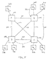
- Figure 2 shows the provider core network 100 with customer edge (CE) devices connected to it.
- the provider core network 100 is used to provide a plurality of data transport services to one or more customers, e.g., transparent LAN services such as virtual private LAN services by which two or more remote customer networks may be joined into a single virtual LAN.
- CE's 202, 204, 206, and 208 are associate d with a first customer or service and are connected to the core provider network 100 through connections to PE's 102, 104, 106, and 108, respectively.
- CE's 210, 212, and 214 are associated with a second customer or service and are connected to the core provider network 100 through connections to PE's 104, 106, and 108, respectively. While two customers/services are shown in Figure 2, in an actual implementation hundred or thousands of services may be provided using the same core provider network.
- the example shown in Figure 2 illustrates a potential problem with using the STP to eliminate loops in a core provider network used to provide a plurality of transport services, such as TLS or similar services.
- the second customer or service is connected to the core network through PE's 104-108. If, as in the example shown in Figure 1B, a single instance of the STP were run for the core provider network, connectivity between these nodes would be lost as a result of paths 116, 118, and 120 being blocked.
- Figures 3A and 3B illustrate one possible set of results that may be obtained by running separate instances of the STP for the first and second services shown in Figure 2.
- Figure 3A shows a possible result of running a first instance of the STP with respect to the first service, associated with CE's 202-208. The result shown is the same as that described above in connection with Figure 1B, with PE 102 being elected as the root bridge and the most direct paths (connections 110, 112, and 114) being identified as the primary paths from the other participating PE's to the root bridge.
- Figure 3B shows a possible result of running a second instance of the STP with respect to the second service, associated with CE's 210-214.
- PE 106 has been elected as the root bridge, and connections 116 and 120 identified as the primary paths from PE's 104 and 108, respectively, to the root bridge.
- a typical provider core network may comprise dozens or more PE's and may be required to support hundreds or thousands of services.
- the overhead and other cost associated with implementing, running, and administering thousands of instances of the STP becomes too costly and may become unmanageable. Therefore, a more scalable solution to the problem described above is required.
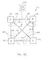
- FIG. 4A illustrates an approach used in some embodiments to implement the STP with respect to a provider core network that supports a large number of services not all of which require the participation of every PE of the core network.
- a virtual core bridge 402 that represents the network core is simulated.
- the virtual core bridge 402 is not an actual physical switch or bridge, but instead is a virtual bridge that is represented at each PE participating in the service by a virtual root bridge protocol data unit (VRBPDU).
- VRBPDU virtual root bridge protocol data unit
- network bridges and switches exchange bridge protocol data units (BPDU) comprising, inter alia, information about themselves and the switch/bridge that they believe to be the root bridge for the spanning tree.
- BPDU bridge protocol data units
- Each node advertises its own bridge identifier and its "priority" (a measure, determined as set for the in the STP standard, of how desirable the switch/bridge is as a candidate for root bridge), as well as the bridge identifier and priority of the bridge that the node believes is the current root bridge.
- the STP uses this information to "elect” the root bridge, as well as to determine at each node which port will be the "root port” for that node, as described above.
- the bridge with the lowest priority zero is the lowest possible priority
- the VRBPDU is configured to represent the network core at each PE participating in the service as a virtual core bridge, such as VCB 402 of Figure 4A. (Note that in the example shown, all four of PE's 102-108 participate in the service. In other embodiments, fewer than all of the PE's may participate.)
- the VRBPDU is associated with a virtual core port (VCP) comprising the PE's mesh connections to the other participating PE's (i.e., to the core of the service domain).
- VCP virtual core port
- the VRBPDU is associated with a VCP 404 comprising connections 110, 112, and 114.
- the VRBPDU is associated with a VCP 406 comprising connections 110, 116, and 118; for PE 106 the VRBPDU is associated with a VCP 408 comprising connections 116, 112, and 120; and for PE 108 the VRBPDU is associated with a VCP 410 comprising connections 114, 118, and 120.
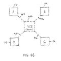
- Figure 4B shows an alternate representation of the VCB 402 and the virtual core ports 404-410 by which PE's 102-108, respectively, are configured to understand themselves to be connected to the VCB 402 for purposes of the STP.
- Each VRBPDU comprises a root priority field set to zero, the lowest possible value, to ensure that the likelihood of another node, e.g., one external to the core network such as a customer bridge, becoming root is negligible. Stated another way, it is unlikely that a customer bridge will have a priority of zero, so setting the priority of the virtual core bridge 402 to zero nearly ensures that the VCB will become the root bridge.
- the VRBPDU is configured at rather than sent to the participating PE's, which ensures that the VRBPDU does not age.
- PE access ports may be used to provide a plurality of virtual ports, such as by using software to define a plurality of service-based access points that share a single physical port.
- a BPDU identifying a bridge other than the VCB as the root bridge with a priority of zero is received, only the service-based access point associated with the service with which the BPDU is associated is blocked, so that other services may continue to use the shared physical port.
- a protocol other than the STP may be used to provide for redundancy and prevent loops within the core network.
- one or more layer 3 forwarding protocols e.g., interior gateway protocols (IGP) such as Open Shortest Path First (OSPF)
- IGP interior gateway protocols
- OSPF Open Shortest Path First
- Some such forwarding protocols provide the features of the STP with advantages such as load sharing, better protocol fault isolation, and proven scalability.
- extending and modifying the STP as described herein ensures that the STP does not interfere with or cause complications with the operation of the IGP forwarding decisions.
- the STP extended as described herein is still useful for providing redundancy between the PE's and equipment outside the network core (e.g., CE's), and for handling forwarding paths outside the core network, e.g., between CE's, that could result in a loop.
- FIG. 5 shows the exemplary network of Figure 2 with potential loop paths 502 and 504 shown.
- Loop path 502 shown in Figure 5 providing a path from CE 204 to the core provider network 100 via PE 104, illustrates the risk that absent a properly configured instance of the STP a CE device might send back into the core network 100 a packet received from the core via a PE to which the CE is connected.
- loop path 504 illustrates that absent a properly configured instance of the STP a PE having a non-mesh connection or path to another PE might send a packet received from the core via a mesh connection to another participating PE via the non-mesh connection, potentially resulting in an undesirable loop. Configuring the PE's to implement the STP extended as described above avoids such loops.
- PE 104 were configured to recognize the core network 100 as comprising a virtual core bridge to which its mesh connections 110, 116, and 118 comprise a virtual core port by which it is connected to the virtual core bridge, and the VCB is configured on PE 104 to have a priority of zero and PE 104 is configured to perform a validity check on received BPDU's as described above to ensure that the VCB remains the root bridge, the path 502 would be prevented from becoming the root port on PE 104, thereby preventing the loop path. Likewise, the path 504 would be prevented from becoming the root port on PE 106, eliminating the potential loop path.
- FIG. 6 is a flow chart illustrating a process used in some embodiments to simulate a virtual core bridge on a core provider network.
- a virtual core port is defined that comprises all of the PE's mesh connections to the core network.
- a conditionally permanent VRBPDU is defined. The VRBPDU is associated with the virtual core port and has a root priority of zero.
- Figure 7 is a flow chart illustrating a process used in some embodiments to perform a validity check on BPDU's received from a customer bridge.
- a BPDU is received.
- step 702 If the root bridge priority of the BPDU is not zero (i.e., it is greater than zero, by definition, since zero is the lowest possible value), the process returns to step 702, where the process begins again when the next BPDU is received. If it is determined in step 706 that the root bridge priority of the BPDU is zero, the process advances to step 708, in which the BPDU is discarded and the path with which the BPDU is associated is placed in the blocking (standby) state for STP purposes, after which the process ends. A port in the block state does not participate in frame forwarding. In some embodiments, after step 708 the process returns to step 702, where the process resumes as subsequent BPDU's are received.
- step 708 comprises placing a port in a blocked or standby state. In some embodiments, as noted above, step 708 comprises placing a service-based access point associatedwith the BPDU in a blocked or standby state.
- Figure 8 shows the exemplary network of Figure 2 with potential loop path 802 shown.
- Figure 8 illustrates the fact that the STP instance running with respect to the provider core network must be able to interact with the customer STP instance(s) to eliminate potential loop paths such as path 802, shown in Figure 8 as providing a path between CE 214 and CE 212.
- a difficulty in interacting with an instance of the STP running on the customer's (or other) network is that different versions or implementations of the STP may use a slightly different format to exchange STP-related data.
- the format of the BPDU may be different, e.g., depending on the approach used to provide a spanning tree topology on a per-VLA N basis (e.g., "q" tags, Cisco TM Per VLAN Spanning Tree (PVLAN), etc.).
- these differences are handled by detecting the format being used on the customer (or other) network and using the detected format to exchange data with the STP instance running on the customer network.
- Figure 9 illustrates a process used in some embodiments to interact with an STP instance running on a customer (or other) network.
- a BPDU or equivalent data unit associated with an instance of the STP running on a customer network is received from the customer network.
- the BPDU or data unit type e.g., format
- BPDU's (or other data units) of the same (or an otherwise compatible) type are used to interact with the STP instance running on the customer network, e.g., as required to prevent paths such as path 802 of Figure 8 from resulting in loops in the network topology.
Abstract
Description
- This application claims priority to U.S. Provisional Patent Application No. 60/466,249 entitled EXTENSIONS TO THE SPANNING TREE PROTOCOL FOR VIRTUAL PRIVATE LAN SERVICES filed April 28, 2003, which is incorporated herein by reference for all purposes.
- The present invention relates generally to networks. More specifically, extensions to the spanning tree protocol (STP) are disclosed.
- The Spanning Tree network protocol (STP) provides path redundancy while preventing undesirable loops in the network. STP defines a tree that spans all switches in an extended network and places selected redundant paths in a standby or blocked state. Specifically, the STP algorithm ensures that if multiple paths exist to the same destination, then all but one will be blocked.
- When using STP to provide for path redundancy and prevent undesirable loops in connection with a core provider network used to provide a plurality of services, not all of which require or involve the participation of all provider edge devices associated with the core network, the spanning tree protocol may yield undesirable results, such as blocking all of the paths that provide connectivity between a subset of provider edge (PE) devices participating in a particular service, e.g., a transparent LAN service (TLS). It is possible to run a separate instance of the STP for each service being provided using the core network, but that approach becomes unmanageable where hundreds or thousands of different services are provided using the same core network. Therefore, an extension to the STP that supports the provision of a large number of services, not each involving the participation of all PE's of a core network, without requiring that a separate instance of the STP be run for each service, is needed.
- In addition, each service may be associated with one or more customer networks, each of which may and probably will be running an instance of the STP (or a similar protocol for preventing loops). However, not every implementation of the STP or similar protocol will be the same. Therefore, there is a need for a way for an instance of the STP running on a core provider network to interact with instances of STP (or similar protocols) running on customer networks connected to the provider's core network.
- Various embodiments of the invention are disclosed in the following detailed description and the accompanying drawings.
- Figure 1A shows an exemplary network in which the spanning tree protocol may be employed.
- Figure 1B illustrates how the spanning tree protocol might operate in the exemplary network of Figure 1A.
- Figure 2 shows the
provider core network 100 with customer edge (CE) devices connected to it. - Figure 3A shows a possible result of running a first instance of the STP with respect to the first service, associated with CE's 202-208.
- Figure 3B shows a possible result of running a second instance of the STP with respect to the second service, associated with CE's 210-214.
- Figure 4A illustrates an approach used in some embodiments to implement the STP with respect to a provider core network that supports a large number of services not all of which require the participation of every PE of the core network.
- Figure 4B shows an alternate representation of the
VCB 402 and the virtual core ports 404-410 by which PE's 102-108, respectively, are configured to understand themselves to be connected to theVCB 402 for purposes of the STP. - Figure 5 shows the exemplary network of Figure 2 with
potential loop paths - Figure 6 is a flow chart illustrating a process used in some embodiments to simulate a virtual core bridge on a core provider network.
- Figure 7 is a flow chart illustrating a process used in some embodiments to perform a validity check on BPDU's received from a customer bridge.
- Figure 8 shows the exemplary network of Figure 2 with
potential loop path 802 shown. - Figure 9 illustrates a process used in some embodiments to interact with an STP instance running on a customer (or other) network.
-
- The invention can be implemented in numerous ways, including as a process, an apparatus, a system, a composition of matter, a computer readable medium such as a computer readable storage medium or a computer network wherein program instructions are sent over optical or electronic communication links. In this specification, these implementations, or any other form that the invention may take, may be referred to as techniques. In general, the order of the steps of disclosed processes may be altered within the scope of the invention.
- A detailed description of one or more embodiments of the invention is provided below along with accompanying figures that illustrate the principles of the invention. The invention is described in connection with such embodiments, but the invention is not limited to any embodiment. The scope of the invention is limited only by the claims and the invention encompasses numerous alternatives, modifications and equivalents. Numerous specific details are set forth in the following description in order to provide a thorough understanding of the invention. These details are provided for the purpose of example and the invention may be practiced according to the claims without some or all of these specific details. For the purpose of clarity, technical material that is known in the technical fields related to the invention has not been described in detail so that the invention is not unnecessarily obscured.
- Extensions to the spanning tree protocol (STP) are disclosed. A virtual core bridge (VCB) that represents the network core is simulated. It is ensured that the virtual core bridge becomes and remains the root bridge. In some embodiments, the root bridge priority associated with the VCB is zero, ensuring that it becomes the root bridge. In some embodiments, a validity check is done on bridge protocol data units (BPDU's) received at a provider edge device from outside the core network to ensure that the VCB will remain the root bridge. Learning to communicate with an instance of the STP (or similar protocol) running on an external (e.g., customer) network connected to the core network is disclosed. The version/type of the STP instance running on the external network is detected, and the core network STP uses the format appropriate to the version/type of STP running on the external network to exchange STP-related data with the external network.
- Figure 1A shows an exemplary network in which the spanning tree protocol may be employed. A
core provider network 100 comprises four provider edge (PE) devices A-D, labeled 102, 104, 106, and 108, respectively, in Figure 1A. PE's 102-108 are connected in a full mesh by mesh connections 110-120. While connections 110-120 comprise mesh connections in a core provider network in this example, the principles described in connection with Figures 1A and 1B apply as well to other types of networks having other types of connection. One can see from Figure 1A that the full mesh of connections 110-120 makes available to each of the PE's 102-108 multiple possible paths to each other node, providing a high degree of redundancy. For example, PE 102 can reachPE 104 either via the direct path ofconnection 110 or indirectly throughPE 106, e.g., via thepath comprising connection 112,PE 106, andconnection 116. However, this configuration also creates the possibility of loops in the network, whereby the same data packet, frame, or other unit of data could arrive at a node (e.g., one of the PE's) via multiple paths, forwarded by more than one other node, resulting in inefficiency and potentially confusion. This risk is present particularly when the communications protocols being used do not result in a data frame "timing out" after a prescribed period, as is the case with, for example,layer 2 LAN protocols. For example, ifPE 102 were to broadcast a data frame to PE's 104, 106, and 108 (e.g., becausePE 102 did not know which of the PE's was associated with the destination address for the data frame), there is a risk thatPE 106, e.g., might forward the frame on to PE's 104 and 108 (e.g., if the destination address were not known to PE 106), one of which might further forward the frame back toPE 102. The spanning tree protocol eliminates such loops by electing one switch or network bridge to function as the "root bridge" for the network (or that part of the network for which the instance of the STP is running), having each participating switch or bridge that is not the root bridge identify as its "root port" the port on that switch or bridge that represents the lowest cost path from that node to the root bridge, and blocking (e.g., by placing in standby or backup mode) paths that might otherwise result in a loop. In this way, the root bridge becomes the root of a minimum spanning tree providing connectivity between all nodes, without loops. Paths placed in standby mode may be activated as needed, e.g., for redundancy or in response to changes in the network topology that generate in changes to the spanning tree. - Figure 1B illustrates how the spanning tree protocol might operate in the exemplary network of Figure 1A. In the example shown,
PE 102 has been elected to function as the root bridge. PE 104 has identified its port associated withconnection 110 as its root port, PE 106 has identified its port associated withconnection 112 as its root port, and PE 108 has identified its port associated withconnection 108 as its root port. The ports on PE's 104, 106, and 108, respectively, associated withconnections - Figure 2 shows the
provider core network 100 with customer edge (CE) devices connected to it. In some embodiments, theprovider core network 100 is used to provide a plurality of data transport services to one or more customers, e.g., transparent LAN services such as virtual private LAN services by which two or more remote customer networks may be joined into a single virtual LAN. In the simplified example shown, CE's 202, 204, 206, and 208 are associate d with a first customer or service and are connected to thecore provider network 100 through connections to PE's 102, 104, 106, and 108, respectively. CE's 210, 212, and 214 are associated with a second customer or service and are connected to thecore provider network 100 through connections to PE's 104, 106, and 108, respectively. While two customers/services are shown in Figure 2, in an actual implementation hundred or thousands of services may be provided using the same core provider network. - The example shown in Figure 2 illustrates a potential problem with using the STP to eliminate loops in a core provider network used to provide a plurality of transport services, such as TLS or similar services. In the example shown, the second customer or service is connected to the core network through PE's 104-108. If, as in the example shown in Figure 1B, a single instance of the STP were run for the core provider network, connectivity between these nodes would be lost as a result of
paths - One potential solution to this problem that has been suggested is to run a separate instance of the STP for each customer/service, such that each service would have its own root bridge and a spanning tree defined to avoid loops within the subset of nodes participating in the service. Figures 3A and 3B illustrate one possible set of results that may be obtained by running separate instances of the STP for the first and second services shown in Figure 2. Figure 3A shows a possible result of running a first instance of the STP with respect to the first service, associated with CE's 202-208. The result shown is the same as that described above in connection with Figure 1B, with
PE 102 being elected as the root bridge and the most direct paths (connections PE 106 has been elected as the root bridge, andconnections - While the approach shown in Figures 3A and 3B avoids having the STP result in a loss of connectivity for a service, the solution does not scale well. A typical provider core network may comprise dozens or more PE's and may be required to support hundreds or thousands of services. As the size of the provider core network and the number of services supported grows, the overhead and other cost associated with implementing, running, and administering thousands of instances of the STP becomes too costly and may become unmanageable. Therefore, a more scalable solution to the problem described above is required.
- Figure 4A illustrates an approach used in some embodiments to implement the STP with respect to a provider core network that supports a large number of services not all of which require the participation of every PE of the core network. For each service, a
virtual core bridge 402 that represents the network core is simulated. Thevirtual core bridge 402 is not an actual physical switch or bridge, but instead is a virtual bridge that is represented at each PE participating in the service by a virtual root bridge protocol data unit (VRBPDU). Under the STP, network bridges and switches exchange bridge protocol data units (BPDU) comprising, inter alia, information about themselves and the switch/bridge that they believe to be the root bridge for the spanning tree. Each node advertises its own bridge identifier and its "priority" (a measure, determined as set for the in the STP standard, of how desirable the switch/bridge is as a candidate for root bridge), as well as the bridge identifier and priority of the bridge that the node believes is the current root bridge. The STP uses this information to "elect" the root bridge, as well as to determine at each node which port will be the "root port" for that node, as described above. The bridge with the lowest priority (zero is the lowest possible priority) will be elected root bridge, with ties being broken based on the bridge identifier. - In some embodiments, the VRBPDU is configured to represent the network core at each PE participating in the service as a virtual core bridge, such as
VCB 402 of Figure 4A. (Note that in the example shown, all four of PE's 102-108 participate in the service. In other embodiments, fewer than all of the PE's may participate.) On each PE, the VRBPDU is associated with a virtual core port (VCP) comprising the PE's mesh connections to the other participating PE's (i.e., to the core of the service domain). For example, forPE 102 the VRBPDU is associated with aVCP 404 comprisingconnections PE 104 the VRBPDU is associated with aVCP 406 comprisingconnections PE 106 the VRBPDU is associated with aVCP 408 comprisingconnections PE 108 the VRBPDU is associated with aVCP 410 comprisingconnections VCB 402 and the virtual core ports 404-410 by which PE's 102-108, respectively, are configured to understand themselves to be connected to theVCB 402 for purposes of the STP. - Each VRBPDU comprises a root priority field set to zero, the lowest possible value, to ensure that the likelihood of another node, e.g., one external to the core network such as a customer bridge, becoming root is negligible. Stated another way, it is unlikely that a customer bridge will have a priority of zero, so setting the priority of the
virtual core bridge 402 to zero nearly ensures that the VCB will become the root bridge. In some embodiments, the VRBPDU is configured at rather than sent to the participating PE's, which ensures that the VRBPDU does not age. - In some embodiments, to further ensure that the VCB remains the root bridge, a validity check is done on each BDPU received at a PE. If the root bridge identifier of a received BPDU does not match the root bridge identifier associated with the VCB and the root bridge priority of the received BPDU is zero, the BPDU is discarded and the port on which the BPDU was received enters the blocked (standby) state. In some embodiments, PE access ports may be used to provide a plurality of virtual ports, such as by using software to define a plurality of service-based access points that share a single physical port. In some such embodiments, if a BPDU identifying a bridge other than the VCB as the root bridge with a priority of zero is received, only the service-based access point associated with the service with which the BPDU is associated is blocked, so that other services may continue to use the shared physical port.
- In some embodiments, a protocol other than the STP may be used to provide for redundancy and prevent loops within the core network. In some embodiments, one or more layer 3 forwarding protocols (e.g., interior gateway protocols (IGP) such as Open Shortest Path First (OSPF)) may be used to provide redundancy and prevent loops in the core network. Some such forwarding protocols provide the features of the STP with advantages such as load sharing, better protocol fault isolation, and proven scalability. In some such embodiments, extending and modifying the STP as described herein ensures that the STP does not interfere with or cause complications with the operation of the IGP forwarding decisions. In embodiments in which a protocol other than the STP is used to provide redundancy and avoid loops in the core network, the STP extended as described herein is still useful for providing redundancy between the PE's and equipment outside the network core (e.g., CE's), and for handling forwarding paths outside the core network, e.g., between CE's, that could result in a loop.
- Figure 5 shows the exemplary network of Figure 2 with
potential loop paths Loop path 502, shown in Figure 5 providing a path fromCE 204 to thecore provider network 100 viaPE 104, illustrates the risk that absent a properly configured instance of the STP a CE device might send back into the core network 100 a packet received from the core via a PE to which the CE is connected. Similarly,loop path 504 illustrates that absent a properly configured instance of the STP a PE having a non-mesh connection or path to another PE might send a packet received from the core via a mesh connection to another participating PE via the non-mesh connection, potentially resulting in an undesirable loop. Configuring the PE's to implement the STP extended as described above avoids such loops. For example, ifPE 104 were configured to recognize thecore network 100 as comprising a virtual core bridge to which itsmesh connections PE 104 to have a priority of zero andPE 104 is configured to perform a validity check on received BPDU's as described above to ensure that the VCB remains the root bridge, thepath 502 would be prevented from becoming the root port onPE 104, thereby preventing the loop path. Likewise, thepath 504 would be prevented from becoming the root port onPE 106, eliminating the potential loop path. - Figure 6 is a flow chart illustrating a process used in some embodiments to simulate a virtual core bridge on a core provider network. In
step 602, on each PE a virtual core port is defined that comprises all of the PE's mesh connections to the core network. In step 604, on each PE a conditionally permanent VRBPDU is defined. The VRBPDU is associated with the virtual core port and has a root priority of zero. - Figure 7 is a flow chart illustrating a process used in some embodiments to perform a validity check on BPDU's received from a customer bridge. In
step 702, a BPDU is received. Instep 704, it is determined whether the root bridge identifier of the BPDU matches the identifier associated with the virtual core bridge. If the root bridge identifier matches the identifier associated with the VCB, the BPDU is processed normally and the process of Figure 7 returns to step 702, where the process begins again when the next BPDU is received. If it is determined instep 704 that the root bridge identifier of the received BPDU does not match the identifier associated with the VCB, the process proceeds to step 706, in which it is determined whether the root bridge priority field has a value of zero. If the root bridge priority of the BPDU is not zero (i.e., it is greater than zero, by definition, since zero is the lowest possible value), the process returns to step 702, where the process begins again when the next BPDU is received. If it is determined instep 706 that the root bridge priority of the BPDU is zero, the process advances to step 708, in which the BPDU is discarded and the path with which the BPDU is associated is placed in the blocking (standby) state for STP purposes, after which the process ends. A port in the block state does not participate in frame forwarding. In some embodiments, afterstep 708 the process returns to step 702, where the process resumes as subsequent BPDU's are received. In some embodiments, the blocked state entered instep 708 persists until the discarded BPDU has aged out in accordance with the Max Info Age timer prescribed by the STP standard. In some embodiments,step 708 comprises placing a port in a blocked or standby state. In some embodiments, as noted above,step 708 comprises placing a service-based access point associatedwith the BPDU in a blocked or standby state. - Figure 8 shows the exemplary network of Figure 2 with
potential loop path 802 shown. Figure 8 illustrates the fact that the STP instance running with respect to the provider core network must be able to interact with the customer STP instance(s) to eliminate potential loop paths such aspath 802, shown in Figure 8 as providing a path betweenCE 214 andCE 212. A difficulty in interacting with an instance of the STP running on the customer's (or other) network is that different versions or implementations of the STP may use a slightly different format to exchange STP-related data. For example, the format of the BPDU may be different, e.g., depending on the approach used to provide a spanning tree topology on a per-VLA N basis (e.g., "q" tags, CiscoTM Per VLAN Spanning Tree (PVLAN), etc.). In some embodiments, these differences are handled by detecting the format being used on the customer (or other) network and using the detected format to exchange data with the STP instance running on the customer network. - Figure 9 illustrates a process used in some embodiments to interact with an STP instance running on a customer (or other) network. In
step 902, a BPDU or equivalent data unit associated with an instance of the STP running on a customer network is received from the customer network. Instep 904, the BPDU or data unit type (e.g., format) is detected. Instep 906, BPDU's (or other data units) of the same (or an otherwise compatible) type are used to interact with the STP instance running on the customer network, e.g., as required to prevent paths such aspath 802 of Figure 8 from resulting in loops in the network topology. - Although the foregoing embodiments have been described in some detail for purposes of clarity of understanding, the invention is not limited to the details provided. There are many alternative ways of implementing the invention. The disclosed embodiments are illustrative and not restrictive.
Claims (14)
- A method for extending the Spanning Tree Protocol (STP) to provide redundancy and avoid loops in the topology of a service domain associated with a data transport service provided using a provider core network, comprising:defining at each of a plurality of provider edge (PE) devices participating in the service, each participating PE being connected to the other participating PE's by a full mesh of mesh connections through the provider core network, a virtual core port that encompasses all of the ports on the PE that are associated with a mesh connection from the PE to one or more other PE's participating in the service;configuring each participating PE to associate the virtual core port with a virtual core bridge representing the core of the service domain; andensuring that the virtual core bridge becomes and remains the root bridge.
- The method of claim 1 wherein configuring each participating PE to associated the virtual core port with a virtual core bridge representing the core of the service domain comprises causing each PE to generate a virtual root bridge protocol data unit (VRBPDU) associated with the virtual core port.
- The method of claim 1 wherein ensuring that the virtual core bridge becomes and remains the root bridge comprises causing each PE to generate a virtual root bridge protocol data unit (VRBPDU) that is associated with the virtual core port and has a root priority of zero.
- The method of claim 1 wherein ensuring that the virtual core bridge becomes and remains the root bridge comprises causing each PE to generate a virtual root bridge protocol data unit (VRBPDU) that does not age out.
- The method of claim 1 further comprising using one or more layer 3 forwarding protocols to provide redundancy within the core network.
- The method of claim 1 ensuring that the virtual core bridge becomes and remains the root bridge comprises performing a validity check on all bridge protocol data units (BPDU's) received at a participating PE on a port other than the virtual core port to ensure that the virtual core bridge remains the STP root bridge.
- The method of claim 6 wherein the validity check comprises determining whether the received BPDU comprises a root bridge identifier that does not match a virtual root bridge identifier associated with the virtual core bridge.
- The method of claim 6 wherein the validity check comprises determining whether the received BPDU comprises a root priority equal to zero.
- The method of claim 6 further comprising, in the event the received BPDU comprises a root bridge identifier that does not match a virtual root bridge identifier associated with the virtual core bridge and has a root priority equal to zero, discarding the BPDU and placing a port associated with the BPDU in a non-forwarding state.
- The method of claim 6 further comprising, in the event the received BPDU comprises a root bridge identifier that does not match a virtual root bridge identifier associated with the virtual core bridge and has a root priority equal to zero, discarding the BPDU and placing a service-based access point associated with the BPDU in a non-forwarding state.
- The method of claim 1 further comprising detecting the format of a data unit associated with an instance of the STP running outside of the core network.
- The method of claim 11 further comprising interacting with the instance of the STP running outside of the core network by sending one or more data units in the detected format.
- A system for extending the Spanning Tree Protocol (STP) to provide redundancy and avoid loops in the topology of a service domain associated with a data transport service provided using a provider core network, comprising:one or more ports configured as mesh connections to one or more provider edge devices participating in the service; anda forwarding engine configured to treat said one or more ports configured as mesh connections as a single virtual core port for purposes of the STP, associate the virtual core port with a virtual core bridge, and ensure that the virtual core port becomes and remains the root bridge.
- A computer program product for extending the Spanning Tree Protocol (STP) to provide redundancy and avoid loops in the topology of a service domain associated with a data transport service provided using a provider core network, the computer program product being embodied in a computer readable medium and comprising computer instructions for:defining at each of a plurality of provider edge (PE) devices participating in the service, each participating PE being connected to the other participating PE's by a full mesh of mesh connections through the provider core network, a virtual core port that encompasses all of the ports on the PE that are associated with a mesh connection from the PE to one or more other PE's participating in the service;configuring each participating PE to associated the virtual core port with a virtual core bridge representing the core of the service domain; andensuring that the virtual core bridge becomes and remains the root bridge.
Applications Claiming Priority (4)
| Application Number | Priority Date | Filing Date | Title |
|---|---|---|---|
| 1997-01-14 | |||
| US46624903P | 2003-04-28 | 2003-04-28 | |
| US466249P | 2003-04-28 | ||
| US10/833,822 US7508774B2 (en) | 2003-04-28 | 2004-04-27 | Extensions to the spanning tree protocol |
Publications (3)
| Publication Number | Publication Date |
|---|---|
| EP1480397A2 true EP1480397A2 (en) | 2004-11-24 |
| EP1480397A3 EP1480397A3 (en) | 2006-01-25 |
| EP1480397B1 EP1480397B1 (en) | 2011-10-12 |
Family
ID=33479249
Family Applications (1)
| Application Number | Title | Priority Date | Filing Date |
|---|---|---|---|
| EP04300238A Expired - Fee Related EP1480397B1 (en) | 2003-04-28 | 2004-04-28 | Extensions to the spanning tree protocol |
Country Status (2)
| Country | Link |
|---|---|
| US (1) | US7508774B2 (en) |
| EP (1) | EP1480397B1 (en) |
Cited By (3)
| Publication number | Priority date | Publication date | Assignee | Title |
|---|---|---|---|---|
| WO2009032648A1 (en) * | 2007-08-30 | 2009-03-12 | Motorola, Inc. | Method and device for providing a bridge in a network |
| CN109547339A (en) * | 2019-01-18 | 2019-03-29 | 深圳市吉祥腾达科技有限公司 | Prevent network from forming the method and system of loop when a kind of wireless router networking |
| CN111314216A (en) * | 2020-02-13 | 2020-06-19 | 深圳市吉祥腾达科技有限公司 | Mixed networking ring prevention method for MESH router |
Families Citing this family (15)
| Publication number | Priority date | Publication date | Assignee | Title |
|---|---|---|---|---|
| US7423980B2 (en) * | 2004-07-01 | 2008-09-09 | Nortel Networks Limited | Full mesh status monitor |
| JP4397292B2 (en) * | 2004-07-09 | 2010-01-13 | 富士通株式会社 | Control packet loop prevention method and bridge device using the same |
| DK1935145T3 (en) * | 2005-10-11 | 2012-04-10 | Ericsson Telefon Ab L M | Process for generating voltage trees |
| US7944853B2 (en) * | 2006-01-06 | 2011-05-17 | Belair Networks Inc. | Virtual root bridge |
| IL176330A0 (en) * | 2006-06-15 | 2007-07-04 | Eci Telecom Ltd | Technique of traffic protection loop-free interconnection for ethernet and/or vpls networks |
| US8223668B2 (en) * | 2006-12-14 | 2012-07-17 | Rockstar Bidco Lp | Method and apparatus for exchanging routing information and the establishment of connectivity across multiple network areas |
| US8743677B2 (en) * | 2009-01-16 | 2014-06-03 | Cisco Technology, Inc. | VPLS N-PE redundancy with STP isolation |
| US8514746B1 (en) * | 2010-11-08 | 2013-08-20 | Juniper Networks, Inc. | Priority inversion with spanning tree protocol to trigger path switching |
| CN102761463A (en) * | 2011-04-29 | 2012-10-31 | 鸿富锦精密工业(深圳)有限公司 | Network equipment and method for implementation of energy conservation and electricity saving of network equipment in local area network |
| CN102340434B (en) | 2011-07-07 | 2014-03-26 | 杭州华三通信技术有限公司 | Multihoming access-based loop avoidance method and edge devices |
| US9571387B1 (en) * | 2012-03-12 | 2017-02-14 | Juniper Networks, Inc. | Forwarding using maximally redundant trees |
| US9191139B1 (en) * | 2012-06-12 | 2015-11-17 | Google Inc. | Systems and methods for reducing the computational resources for centralized control in a network |
| US8902794B2 (en) * | 2012-09-27 | 2014-12-02 | Cisco Technology, Inc. | System and method for providing N-way link-state routing redundancy without peer links in a network environment |
| TWI599260B (en) * | 2016-04-13 | 2017-09-11 | 正文科技股份有限公司 | Local communication wireless network system and method thereof |
| US10554425B2 (en) | 2017-07-28 | 2020-02-04 | Juniper Networks, Inc. | Maximally redundant trees to redundant multicast source nodes for multicast protection |
Citations (2)
| Publication number | Priority date | Publication date | Assignee | Title |
|---|---|---|---|---|
| US20010025318A1 (en) | 2000-03-17 | 2001-09-27 | Anritsu Corporation | Apparatus and method for configuring spanning tree and spanning tree protocol system and bridge system |
| US20020052936A1 (en) | 1997-12-24 | 2002-05-02 | Silvano Gai | Method and apparatus for rapidly reconfiguring computers networks executing the spanning tree algorithm |
Family Cites Families (8)
| Publication number | Priority date | Publication date | Assignee | Title |
|---|---|---|---|---|
| US5878232A (en) * | 1996-12-27 | 1999-03-02 | Compaq Computer Corporation | Dynamic reconfiguration of network device's virtual LANs using the root identifiers and root ports determined by a spanning tree procedure |
| US6188694B1 (en) * | 1997-12-23 | 2001-02-13 | Cisco Technology, Inc. | Shared spanning tree protocol |
| US6515969B1 (en) | 1999-03-01 | 2003-02-04 | Cisco Technology, Inc. | Virtual local area network membership registration protocol for multiple spanning tree network environments |
| US6765881B1 (en) * | 2000-12-06 | 2004-07-20 | Covad Communications Group, Inc. | Virtual L2TP/VPN tunnel network and spanning tree-based method for discovery of L2TP/VPN tunnels and other layer-2 services |
| US7076594B2 (en) * | 2000-12-22 | 2006-07-11 | Cisco Technology, Inc. | Apparatus and method for preventing one way connectivity loops in a computer network |
| US7145878B2 (en) | 2001-07-27 | 2006-12-05 | Corrigent Systems Ltd. | Avoiding overlapping segments in transparent LAN services on ring-based networks |
| US7292581B2 (en) * | 2002-10-24 | 2007-11-06 | Cisco Technology, Inc. | Large-scale layer 2 metropolitan area network |
| EP1588529B9 (en) * | 2002-12-20 | 2008-03-12 | Enterasys Networks, Inc. | Method and apparatus for determining a spanning tree |
-
2004
- 2004-04-27 US US10/833,822 patent/US7508774B2/en not_active Expired - Fee Related
- 2004-04-28 EP EP04300238A patent/EP1480397B1/en not_active Expired - Fee Related
Patent Citations (2)
| Publication number | Priority date | Publication date | Assignee | Title |
|---|---|---|---|---|
| US20020052936A1 (en) | 1997-12-24 | 2002-05-02 | Silvano Gai | Method and apparatus for rapidly reconfiguring computers networks executing the spanning tree algorithm |
| US20010025318A1 (en) | 2000-03-17 | 2001-09-27 | Anritsu Corporation | Apparatus and method for configuring spanning tree and spanning tree protocol system and bridge system |
Cited By (4)
| Publication number | Priority date | Publication date | Assignee | Title |
|---|---|---|---|---|
| WO2009032648A1 (en) * | 2007-08-30 | 2009-03-12 | Motorola, Inc. | Method and device for providing a bridge in a network |
| CN109547339A (en) * | 2019-01-18 | 2019-03-29 | 深圳市吉祥腾达科技有限公司 | Prevent network from forming the method and system of loop when a kind of wireless router networking |
| CN109547339B (en) * | 2019-01-18 | 2021-07-09 | 深圳市吉祥腾达科技有限公司 | Method and system for preventing network from forming loop in wireless router networking |
| CN111314216A (en) * | 2020-02-13 | 2020-06-19 | 深圳市吉祥腾达科技有限公司 | Mixed networking ring prevention method for MESH router |
Also Published As
| Publication number | Publication date |
|---|---|
| US7508774B2 (en) | 2009-03-24 |
| EP1480397A3 (en) | 2006-01-25 |
| EP1480397B1 (en) | 2011-10-12 |
| US20040252634A1 (en) | 2004-12-16 |
Similar Documents
| Publication | Publication Date | Title |
|---|---|---|
| US7508774B2 (en) | Extensions to the spanning tree protocol | |
| US9178762B2 (en) | Configuring networks including spanning trees | |
| US8442064B2 (en) | Virtual link aggregation of network traffic in an aggregation switch | |
| US7672227B2 (en) | Loop prevention system and method in a stackable ethernet switch system | |
| EP2891286B1 (en) | System and method for supporting discovery and routing degraded fat-trees in a middleware machine environment | |
| US7778205B2 (en) | System and method for implementing virtual ports within ring networks | |
| US8155030B2 (en) | Method and apparatus for network tree management | |
| CN110098992A (en) | For transmitting the particular virtual local area network of peer business among the switches | |
| US9647928B2 (en) | OSPF point-to-multipoint over broadcast or NBMA mode | |
| US8855124B2 (en) | Forwarding inter-switch connection (ISC) frames in a network-to-network interconnect topology | |
| EP3698520B1 (en) | A communication routing system | |
| US9054983B2 (en) | Centralized control and management planes for different independent switching domains | |
| CN106170952A (en) | For disposing the method and system of maximum redundancy tree in a data network | |
| JP2003218901A (en) | Frame relay system, frame relaying apparatus, relaying apparatus, and network | |
| US20080159290A1 (en) | Method of Preventing Transport Leaks in Hybrid Switching Networks | |
| US8837329B2 (en) | Method and system for controlled tree management | |
| WO2010069382A1 (en) | Method and apparatus for transferring data packets between a first network and a second network | |
| EP1341349A1 (en) | Method and apparatus for routing data frames | |
| US10205661B1 (en) | Control messages for scalable satellite device clustering control in a campus network | |
| US10284468B1 (en) | E-channel identifiers (ECIDS) for scalable satellite device clustering control in a campus network |
Legal Events
| Date | Code | Title | Description |
|---|---|---|---|
| PUAI | Public reference made under article 153(3) epc to a published international application that has entered the european phase |
Free format text: ORIGINAL CODE: 0009012 |
|
| AK | Designated contracting states |
Kind code of ref document: A2 Designated state(s): AT BE BG CH CY CZ DE DK EE ES FI FR GB GR HU IE IT LI LU MC NL PL PT RO SE SI SK TR |
|
| AX | Request for extension of the european patent |
Extension state: AL HR LT LV MK |
|
| PUAL | Search report despatched |
Free format text: ORIGINAL CODE: 0009013 |
|
| AK | Designated contracting states |
Kind code of ref document: A3 Designated state(s): AT BE BG CH CY CZ DE DK EE ES FI FR GB GR HU IE IT LI LU MC NL PL PT RO SE SI SK TR |
|
| AX | Request for extension of the european patent |
Extension state: AL HR LT LV MK |
|
| 17P | Request for examination filed |
Effective date: 20060725 |
|
| AKX | Designation fees paid |
Designated state(s): DE ES FR GB IT |
|
| 17Q | First examination report despatched |
Effective date: 20070615 |
|
| GRAP | Despatch of communication of intention to grant a patent |
Free format text: ORIGINAL CODE: EPIDOSNIGR1 |
|
| GRAS | Grant fee paid |
Free format text: ORIGINAL CODE: EPIDOSNIGR3 |
|
| GRAA | (expected) grant |
Free format text: ORIGINAL CODE: 0009210 |
|
| AK | Designated contracting states |
Kind code of ref document: B1 Designated state(s): DE ES FR GB IT |
|
| REG | Reference to a national code |
Ref country code: GB Ref legal event code: FG4D |
|
| REG | Reference to a national code |
Ref country code: DE Ref legal event code: R096 Ref document number: 602004034800 Country of ref document: DE Effective date: 20111208 |
|
| PLBE | No opposition filed within time limit |
Free format text: ORIGINAL CODE: 0009261 |
|
| STAA | Information on the status of an ep patent application or granted ep patent |
Free format text: STATUS: NO OPPOSITION FILED WITHIN TIME LIMIT |
|
| PG25 | Lapsed in a contracting state [announced via postgrant information from national office to epo] |
Ref country code: IT Free format text: LAPSE BECAUSE OF FAILURE TO SUBMIT A TRANSLATION OF THE DESCRIPTION OR TO PAY THE FEE WITHIN THE PRESCRIBED TIME-LIMIT Effective date: 20111012 |
|
| 26N | No opposition filed |
Effective date: 20120713 |
|
| REG | Reference to a national code |
Ref country code: DE Ref legal event code: R097 Ref document number: 602004034800 Country of ref document: DE Effective date: 20120713 |
|
| PG25 | Lapsed in a contracting state [announced via postgrant information from national office to epo] |
Ref country code: ES Free format text: LAPSE BECAUSE OF FAILURE TO SUBMIT A TRANSLATION OF THE DESCRIPTION OR TO PAY THE FEE WITHIN THE PRESCRIBED TIME-LIMIT Effective date: 20120123 |
|
| REG | Reference to a national code |
Ref country code: FR Ref legal event code: TP Owner name: ALCATEL-LUCENT USA INC., US Effective date: 20130619 |
|
| REG | Reference to a national code |
Ref country code: FR Ref legal event code: GC Effective date: 20140225 |
|
| REG | Reference to a national code |
Ref country code: FR Ref legal event code: RG Effective date: 20141015 |
|
| REG | Reference to a national code |
Ref country code: FR Ref legal event code: PLFP Year of fee payment: 12 |
|
| REG | Reference to a national code |
Ref country code: FR Ref legal event code: PLFP Year of fee payment: 13 |
|
| PGFP | Annual fee paid to national office [announced via postgrant information from national office to epo] |
Ref country code: GB Payment date: 20160421 Year of fee payment: 13 Ref country code: DE Payment date: 20160421 Year of fee payment: 13 |
|
| PGFP | Annual fee paid to national office [announced via postgrant information from national office to epo] |
Ref country code: FR Payment date: 20160421 Year of fee payment: 13 |
|
| REG | Reference to a national code |
Ref country code: DE Ref legal event code: R119 Ref document number: 602004034800 Country of ref document: DE |
|
| GBPC | Gb: european patent ceased through non-payment of renewal fee |
Effective date: 20170428 |
|
| REG | Reference to a national code |
Ref country code: FR Ref legal event code: ST Effective date: 20171229 |
|
| PG25 | Lapsed in a contracting state [announced via postgrant information from national office to epo] |
Ref country code: FR Free format text: LAPSE BECAUSE OF NON-PAYMENT OF DUE FEES Effective date: 20170502 Ref country code: DE Free format text: LAPSE BECAUSE OF NON-PAYMENT OF DUE FEES Effective date: 20171103 |
|
| PG25 | Lapsed in a contracting state [announced via postgrant information from national office to epo] |
Ref country code: GB Free format text: LAPSE BECAUSE OF NON-PAYMENT OF DUE FEES Effective date: 20170428 |