EP1486258A2 - Disposable paint cup attachment system for gravity-feed paint sprayer - Google Patents
Disposable paint cup attachment system for gravity-feed paint sprayer Download PDFInfo
- Publication number
- EP1486258A2 EP1486258A2 EP04009885A EP04009885A EP1486258A2 EP 1486258 A2 EP1486258 A2 EP 1486258A2 EP 04009885 A EP04009885 A EP 04009885A EP 04009885 A EP04009885 A EP 04009885A EP 1486258 A2 EP1486258 A2 EP 1486258A2
- Authority
- EP
- European Patent Office
- Prior art keywords
- container
- liner
- fluid
- paint
- walled
- Prior art date
- Legal status (The legal status is an assumption and is not a legal conclusion. Google has not performed a legal analysis and makes no representation as to the accuracy of the status listed.)
- Withdrawn
Links
Images


Classifications
-
- B—PERFORMING OPERATIONS; TRANSPORTING
- B05—SPRAYING OR ATOMISING IN GENERAL; APPLYING FLUENT MATERIALS TO SURFACES, IN GENERAL
- B05B—SPRAYING APPARATUS; ATOMISING APPARATUS; NOZZLES
- B05B7/00—Spraying apparatus for discharge of liquids or other fluent materials from two or more sources, e.g. of liquid and air, of powder and gas
- B05B7/24—Spraying apparatus for discharge of liquids or other fluent materials from two or more sources, e.g. of liquid and air, of powder and gas with means, e.g. a container, for supplying liquid or other fluent material to a discharge device
- B05B7/2402—Apparatus to be carried on or by a person, e.g. by hand; Apparatus comprising containers fixed to the discharge device
- B05B7/2478—Gun with a container which, in normal use, is located above the gun
-
- B—PERFORMING OPERATIONS; TRANSPORTING
- B05—SPRAYING OR ATOMISING IN GENERAL; APPLYING FLUENT MATERIALS TO SURFACES, IN GENERAL
- B05B—SPRAYING APPARATUS; ATOMISING APPARATUS; NOZZLES
- B05B7/00—Spraying apparatus for discharge of liquids or other fluent materials from two or more sources, e.g. of liquid and air, of powder and gas
- B05B7/24—Spraying apparatus for discharge of liquids or other fluent materials from two or more sources, e.g. of liquid and air, of powder and gas with means, e.g. a container, for supplying liquid or other fluent material to a discharge device
- B05B7/2402—Apparatus to be carried on or by a person, e.g. by hand; Apparatus comprising containers fixed to the discharge device
- B05B7/2405—Apparatus to be carried on or by a person, e.g. by hand; Apparatus comprising containers fixed to the discharge device using an atomising fluid as carrying fluid for feeding, e.g. by suction or pressure, a carried liquid from the container to the nozzle
- B05B7/2408—Apparatus to be carried on or by a person, e.g. by hand; Apparatus comprising containers fixed to the discharge device using an atomising fluid as carrying fluid for feeding, e.g. by suction or pressure, a carried liquid from the container to the nozzle characterised by the container or its attachment means to the spray apparatus
-
- B—PERFORMING OPERATIONS; TRANSPORTING
- B05—SPRAYING OR ATOMISING IN GENERAL; APPLYING FLUENT MATERIALS TO SURFACES, IN GENERAL
- B05B—SPRAYING APPARATUS; ATOMISING APPARATUS; NOZZLES
- B05B7/00—Spraying apparatus for discharge of liquids or other fluent materials from two or more sources, e.g. of liquid and air, of powder and gas
- B05B7/24—Spraying apparatus for discharge of liquids or other fluent materials from two or more sources, e.g. of liquid and air, of powder and gas with means, e.g. a container, for supplying liquid or other fluent material to a discharge device
- B05B7/2402—Apparatus to be carried on or by a person, e.g. by hand; Apparatus comprising containers fixed to the discharge device
- B05B7/2481—Apparatus to be carried on or by a person, e.g. by hand; Apparatus comprising containers fixed to the discharge device with a flexible container for liquid or other fluent material
-
- B—PERFORMING OPERATIONS; TRANSPORTING
- B05—SPRAYING OR ATOMISING IN GENERAL; APPLYING FLUENT MATERIALS TO SURFACES, IN GENERAL
- B05B—SPRAYING APPARATUS; ATOMISING APPARATUS; NOZZLES
- B05B11/00—Single-unit hand-held apparatus in which flow of contents is produced by the muscular force of the operator at the moment of use
- B05B11/01—Single-unit hand-held apparatus in which flow of contents is produced by the muscular force of the operator at the moment of use characterised by the means producing the flow
- B05B11/02—Membranes or pistons acting on the contents inside the container, e.g. follower pistons
- B05B11/026—Membranes separating the content remaining in the container from the atmospheric air to compensate underpressure inside the container
- B05B11/027—Membranes separating the content remaining in the container from the atmospheric air to compensate underpressure inside the container inverted during outflow of content
-
- Y—GENERAL TAGGING OF NEW TECHNOLOGICAL DEVELOPMENTS; GENERAL TAGGING OF CROSS-SECTIONAL TECHNOLOGIES SPANNING OVER SEVERAL SECTIONS OF THE IPC; TECHNICAL SUBJECTS COVERED BY FORMER USPC CROSS-REFERENCE ART COLLECTIONS [XRACs] AND DIGESTS
- Y10—TECHNICAL SUBJECTS COVERED BY FORMER USPC
- Y10S—TECHNICAL SUBJECTS COVERED BY FORMER USPC CROSS-REFERENCE ART COLLECTIONS [XRACs] AND DIGESTS
- Y10S239/00—Fluid sprinkling, spraying, and diffusing
- Y10S239/14—Paint sprayers
Definitions
- the present invention is directed to a fluid supply cup for a fluid applicator, more particularly to a paint supply cup for a paint sprayer.
- Fluid is typically delivered to fluid applicators, such as paint sprayers, in one of three ways.
- the fluid may be fed through a hose connected to a remote pressurized source.
- the fluid is generally placed in a cup attached to the sprayer.
- the cup is suspended below a front end of a body on the sprayer and the fluid is fed to a nozzle by suction or aspiration induced by atomization air flow through the sprayer.
- This type of sprayer is commonly referred to as a suction feed sprayer.
- the cup may be pressurized to increase the fluid application rate.
- a cup is sometimes mounted above the sprayer body to feed the fluid via gravity to the sprayer so that less air pressure is needed to aspirate the paint, usually referred to as a gravity feed sprayer.
- Disposable cups and liners have been developed to avoid contamination between batches and to minimize the amount of cleaning needed between applications.
- U.S. Patent 5,816,501 to LoPresti et al. teaches a disposable collapsible liner for a suction feed sprayer, wherein the liner is within a paint jar and paint is drawn through a feed tube. However, the liner is subject to being drawn into the tube opening via suction, which can block the flow of paint through the tube.
- U.S. Patent 5,582,350 to Kosmyna et al. teaches a non-disposable gravity feed paint cup with a disposable liner.
- the liner requires the installation of a port with a special tool and takes considerable time and effort. Further, the liner is hard to remove without spilling paint into the paint cup, which requires cleaning of the cup.
- a novel fluid supply cup comprises a flexible liner integral with a container having an opening and a vent.
- a novel method of manufacturing a lined container includes the steps of molding a container having a vented mick-walled portion and an integral flexible thin-walled liner, and folding the thin-walled liner into the thick-walled portion.
- an improved method of applying a fluid comprises the steps of providing a flexible liner integral with a container having an opening and a vent, loading fluid into the liner, engaging the container with a fluid applicator, flowing the fluid out of the liner and into the fluid applicator, collapsing the liner, and flowing the fluid out of the fluid applicator.
- the fluid applicator is a sprayer
- the flowing step comprises spraying the fluid out of the sprayer.
- a fluid supply cup 10 is shown for feeding fluid to a fluid applicator 2.
- the novel fluid supply cup 10 includes a flexible liner 14 integral with a container 12 having an opening 16 (best shown in FIG. 2) and a vent 18.
- fluid supply cup 10 is for feeding fluid to a sprayer.
- fluid supply cup 10 is a paint cup for feeding paint to a paint sprayer 2; therefore the present invention will be described for a paint sprayer, such as a gravity feed paint sprayer for use in applying paint 1 to coat substrate surfaces.
- paint sprayer 2 is used in the automotive refinishing market, such as automobile body shops, for repainting automobiles. Paint cup 10 of the present invention is easy for an operator to install and is inexpensive to manufacture, saving the operators both time and money.
- fluid supply cup 10 is described herein as a paint cup, it alternatively can be used for supplying other flowable fluids, such as beverages, foods, or condiments, for example ketchup, gasoline, petrochemicals and hydrocarbons, water, water-based solutions, solvent-based solutions, emulsions, and adhesives.
- the fluid being supplied must be compatible with fluid supply cup 10 and should be applied in a similar manner as paint from paint cup 10.
- a paint sprayer 2 is shown in FIG. 1 and includes a body 3, a nozzle assembly 4 secured to a front end 5 of body 3, and a handle 6 depending from a rear end 7 of body 3.
- a trigger 8 is pivotally secured to body 3 for the manual actuation of sprayer 2.
- a top mounted, gravity feed paint cup 10 is mounted to body 3 via an adapter 22 near front end 5 for feeding paint to nozzle assembly 4.
- An air connector 9 is connected to an air hose (not shown) for the delivery of pressurized air to nozzle assembly 4, wherein the delivery of pressurized air is controlled by trigger 8.
- Compressed air from connector 9 is delivered through an internal passage (not shown) to nozzle assembly 4 and the compressed air acts to atomize paint and deliver it through nozzle assembly 4 to spray paint 1 about a spray axis 11. Paint 1 is delivered to nozzle assembly 4 via gravity from paint cup 10. The level of paint 1 in paint cup 10 must be higher than the sprayer connection channel 13, or else paint 1 will not feed via gravity to the nozzle assembly 4, a condition known as starvation.
- Novel paint cup 10 of the present invention provides an inexpensive, easy to use disposable container for the delivery of paint 1 to sprayer 2.
- Novel paint cup 10 includes a container 12 having an opening 16, best seen in FIG. 2, a,vent 18, and a flexible liner 14 integral with container 12.
- liner 14 is integrally formed with container 12 at joint 20 near opening 16. Paint 1 is loaded into liner 14 and container 12 is engaged with sprayer 2 so that the paint 1 can be fed to nozzle assembly 4.
- container 12 includes a generally cylindrical side wall 24 having a generally open first end 26 defining opening 16 into container 12 and a base wall 30 at a second end 28, wherein side wall 24 and base wall 30 surround an interior 32 of container 12.
- Side wall 24 includes a side interior surface 34 and base wall 30 includes a base interior surface 36.
- vent 18 is included generally at second end 28, such as in base wall 30, shown in FIG. 2. Vent 18 allows air to flow into the interior 32 of container 12, providing vacuum relief so that liner 14 may collapse (described below).
- side wall 24c of container 12c is generally frusto-conical in shape so that side wall 24c is slanted slightly, as shown in FIG. 9, so that a plurality of paint cups 10c can be stacked for easy storage and dispensation.
- the walls of container 12, such as walls 24 and 30, are relatively thick in relation to flexible liner 14. Walls 24, 30 should be thick enough so that container is generally stiff and rigid and will not easily collapse. In one embodiment, the thickness of walls 24, 30 is between about 0.02 inches and about 0.06 inches, preferably about 0.025 inches. The thickness of walls 24, 30 may be dependent on the material of construction of container 12.
- Side wall 24 can include graduations 38 indicating the level of paint 1 in paint cup 10.
- Graduations 38 can act as proportional indicators to indicate the levels of one or more fluids that should be added to paint cup 10 to provide a predetermined ratio between the liquids. For example, a certain amount of a'base paint color can be mixed with tinting additives at a predetermined ratio to match a desired color for an automobile.
- Container 12 also includes a means for connection to sprayer 2.
- the means for connection is threading 40 at first end 26 which engages directly with adapter 22 via adapter threading 42 so that paint cup 10 is releasably engageable with sprayer 2.
- the means for connection could also be a bayonet connection (not shown), or a snap engagement (not shown) between container 12 and adapter 22.
- the connection between container 12 and adapter 22b can be via a lid 44, see FIG. 8, wherein container 12 can be connected to lid 44 with threading 40 engaging with lid threading 45, and lid 44 can be connected to adapter 22b via threading 46.
- Container 12 can engage with lid 44 and lid 44 can engage with adapter 22b by other connection means than a threaded connection, such as a bayonet connection, a snap engagement, or a self-locking taper engagement between the inlet connection and the container (not shown).
- a threaded connection such as a bayonet connection, a snap engagement, or a self-locking taper engagement between the inlet connection and the container (not shown).
- Novel self-locking tapered connections are described in more detail in the commonly assigned, co-pending patent application with Attorney Docket # 14115 filed contemporaneously herewith, the disclosure of which is incorporated herein by reference.
- lid 44 keeps paint cup 10 sealed until lid 44 is engaged with adapter 22.
- lid 44 includes a perforable membrane 47 which is broken when adapter 22 is engaged with lid 44, shown in FIG. 8. After container 12 has been engaged with lid 44, paint 1 is sealed within paint cup 10 because air, water vapor, and other materials cannot pass through membrane 47.
- the means for connection create a tight hermetic seal between container 12 and adapter 22 or between container 12 and lid 44 and between lid 44 and adapter 22 so that paint cup 10 is water tight and air tight during operation of sprayer 2 to prevent the escape of solvents, causing premature drying of paint 1 and the formation of a skin layer. Also, water can degrade the quality of paint 1, causing contamination or discoloration of the paint.
- container 12 can have an interior volume of between about 8 fluid ounces and about 2.5 gallons, preferably between about 16 fluid ounces and about one liter.
- a one liter generally cylindrical container 12 has a length of about 4 inches and a diameter of about 6 inches.
- container 12 can have different proportions or geometry.
- the size and shape of container 12 is conducive to the automobile refinishing industry so that sprayer 2 and paint cup 10 are not unwieldy or overly heavy for an operator to handle.
- container 12 is made from a translucent material so that the level of paint 1 can be seen through container 12.
- Container 12 should also be relatively durable and resistant to collapsing, be made from a relatively inexpensive material and be inexpensive to manufacture so that container 12 can be disposable, and be made from a material that is substantially unreactive, preferably unreactive to the fluid in fluid supply cup 10.
- container 12 is made from a molded plastic, such as polyethylene or polypropylene.
- container 12 is molded from low-density polyethylene.
- flexible liner 14 is located within interior 32 of container 12.
- Liner 14 is thin and flexible so that it is capable of collapsing as paint 1 flows out of paint cup 10 and into sprayer 2 while still preventing the inflow of air into liner 14.
- a partial vacuum is formed within liner 14 due to fluid displacement.
- liner 14 is flexible and vent 18 allows air to flow into interior 32 of container, atmospheric pressure offsets the vacuum formed in liner 14, and causes liner 14 to collapse, as shown in FIG. 5.
- the thickness of liner 14 is relatively thinner than the thickness of walls 24, 30 of container 12. Liner 14 should be thin enough so that it is flexible, softer than container 12, pliable, and insertable into interior 32 of container 12. In one embodiment, the thickness of liner 14 is between about 0.004 inches and about 0.015 inches, and preferably between about 0.005 inches and about 0.01 inches.
- Flexible liner 14 is integral with container 12.
- liner 14 is integrally molded with container 12 so that they are formed continuously, best shown in FIG. 2, such as by injection blow molding flexible liner 14 and container 12 in the same process as described below.
- liner 14 is integral with container 12 at joint 20 at first end 26 around opening 16, as shown in FIGS. 2 and 3, so that liner 14 will be easily invertable into interior 32 of container 12.
- liner 14b and container 12b are molded or formed separately and adhered to each other to form paint cup 10b.
- Liner 14b can be adhered or attached to container 12b via, for example, adhesives, plastic weldment, sonic weldment, molecular diffusion, or other methods of fusing plastic.
- liner 14b is adhered to container 12b at joint 20b near opening 16b.
- liner 14b includes a portion 48 that extends past opening 16b to cover threading 40b so that when container 12b is threadingly engaged with adapter 22, so that portion 48 of liner 14b will act as an extra seal between container 12b and adapter 22 to prevent leakage of paint 1.
- liner 14 substantially conforms to interior surfaces 34, 36 of container 12 when liner 14 is not collapsed, still more preferably so that there is full geometric conformity between interior surfaces 34, 36 and liner 14. Conformity of liner 14 preferred so that the level of paint 1 in liner 14 can most accurately be measured with graduations 38. Accurate indication of fluid level is particularly important during mixing of multiple fluids in predetermined ratios.
- flexible liner 14 is preferably made from a translucent material so that the paint level can be seen.
- Liner should also be made from a material that can be pliable and foldable, and that is unreactive with the fluid in fluid supply cup 10. Further, the material of liner 14 should be inexpensive, and liner 14 should be inexpensive to manufacture.
- liner 14 is made from a moldable plastic, such as polyethylene or polypropylene. In a preferred embodiment, liner 14 is molded from low density polyethylene.
- paint cup 10 in order to connect paint cup 10 with sprayer 2, the operator simply has to engage container 12 with adapter 22, or with lid 44 and then engage lid 44 with adapter 22b as in FIG. 8, which requires very little time or effort on the part of the operator.
- the easy assembly of paint cup 10 offers a significant savings of time and effort on the part of operators over traditional paint cups, which require significant assembly of several complicated parts.
- paint cup 10 is inexpensive to manufacture so that it can be disposable without being overly expensive.
- adapter 22 provides a connection between paint cup 10 and sprayer 2 and provides a path for paint 1 to flow from paint cup 10 into sprayer body 3.
- Adapter 22 can engage directly with container 12 at opening 16, such as between container threading 40 and adapter threading 42, or adapter 22 can engage with a lid 44.
- adapter 22 is a mass produced machined adapter and the connection between adapter 22 and sprayer body 3 is a conventional connection, such as threaded engagement between threading 49 on adapter 22 and sprayer threading 50, so that adapter may be releasably connected to several sprayers 2.
- adapter also includes a filter (not shown) to filter impurities, such as dust or other particulates, from flowing into sprayer 2 so that the impurities will not be applied to the surface being painted.
- adapter 22 is shown as being one piece, it is envisioned that adapter 22 can have other configurations, such as an adjustable adapter that allows the orientation of container 12 to be changed to ensure that paint 1 will flow into sprayer 2.
- a novel adjustable adapter is disclosed in the commonly assigned, co-pending patent application with Attorney Docket #14114 filed contemporaneously herewith, the disclosure of which is incorporated herein by reference.
- a storage lid 52 is provided for covering paint cup 10 when painting is completed or temporarily stopped.
- the exact amount of paint 1 required may not be easy to determine, and there is frequently left over paint 1.
- storage lid 52 includes a means for connection to container, such as storage lid threading 54 that engages with container threading 40, to cover opening 16 and provide a tight, hermetic seal with paint cup 10, so that left over paint 1 can be stored easily.
- Some paints 1 have a shelf life of up to about 3 days or more.
- the top 56 of storage lid 52 generally complements the base wall 30 of container 12 so that multiple covered paint cups 10 can be stacked.
- New and improved paint cup 10 is made by a novel method including the steps of molding a container, such as paint cup 10 shown in FIG. 2, having a vented thick-walled portion and an integral flexible thin-walled liner, and folding the thin-walled liner into the thick-walled portion.
- a container such as paint cup 10 shown in FIG. 2
- the thick-walled portion is container 12
- the thin-walled liner is flexible liner 14.
- Molding of liner 14 and container 12 are preferably done by a process wherein liner 14 and container 12 are integrally formed so that liner 14 and container 12 are molded as a single piece.
- the molding process forms a generally closed container, such as the generally closed cylinder shown in FIG. 3, wherein the thickness of the walls of the cylinder abruptly diminishes along the length of the cylinder between thin-walled liner 14 and thick-walled container 12.
- molding of liner 14 and container 12 comprises a two-step injection blow molding process.
- the two-step process requires precision control of a parison used to mold both liner 14 and container 12.
- Liner 14 injection molded in a first step at a relatively low pressure, wherein the temperature, pressure, and other molding conditions should be tightly controlled. After injection blow molding of liner 14, the pressure is increased to a relatively high pressure, to injection blow mold container 12.
- Injection blow molding of liner 14 and container 12 is accomplished through a blow hole formed at the base of container 12.
- hole 18 acts as the'blow hole during the molding process.
- the same hole 18 can be used to vent air into the interior 32 of container 12 during subsequent use of paint cup 10.
- Liner 14 and container 12 can be molded by other means, such as injection molding, rotational molding, suction molding, or extrusion molding. Injection blow molding is preferred because it is an inexpensive process. Alternatively, molding of liner 14 and container 12 can be separate and liner and container 12 can be made integral by adhering liner 14 to container.
- liner 14 is folded into container 12 to form a lined paint cup 10, shown in FIG. 2.
- Folding of liner 14 into container 12 can be done mechanically, such as by air pressure, applied to liner 14 to force it into the interior 32 of container 12, or by forming a partial vacuum in interior 32 of container 12 so that liner 14 is drawn into container 12.
- liner 14 is mechanically inserted into container 12 with assistance from a partial vacuum formed in interior 32 through vent 18.
- folding liner 14 in container 12 includes substantially conforming liner 14 to interior surfaces 34, 36 of container 12.
- conforming liner 14 to surfaces 34, 36 is accomplished by applying air pressure to liner 14 so that there is full geometric conformity between liner 14 and interior surfaces 34,36.
- a novel method of applying a fluid comprises the steps of providing a flexible liner 14 integral with a container 12 having an opening 16 and a vent 18, loading fluid, such as paint 1, into liner 14, engaging container 12 with a fluid applicator, flowing the fluid out of liner 14 and into the fluid applicator 2, collapsing liner 14, and flowing the fluid out of the fluid applicator.
- the flowing step comprises spraying the fluid out of sprayer 2 and in another method, sprayer 2 is a paint sprayer for spraying paint 1 onto a surface, such as the body of an automobile.
- the loading step includes loading paint into paint cup 10.
- the loading step can also comprise loading paint into liner 14 followed by loading a second fluid, such as another paint, tinting additives, or solvents, in predetermined ratios to create paint having a desired color.
- a second fluid such as another paint, tinting additives, or solvents
- the step of engaging container 12 with sprayer 2 can be accomplished by engaging container 12 directly with an adapter 22 connected to sprayer 2, shown in FIGS. 1 and 4, or by engaging container 12 with a lid 44 followed by engaging lid 44 with adapter 22b, as shown in FIG. 8.
- the collapsing step includes collapsing liner 14 due to a partial vacuum formed as paint 1 is drawn out of liner 14 and into sprayer 2.
- the inventive method can also include the step of covering container 12 with a storage lid 52 for the storage or disposal of left-over paint 1 in paint cup 10.
- the present invention provides an inexpensive and disposable fluid supply cup that requires little assembly on the part of an operator and that can be easily stored and disposed.
- the novel fluid supply cup comprises a flexible liner integral with a container having an opening and a vent.
- a novel method of manufacturing a lined fluid supply container comprises the steps of molding a container having a vented thick-walled portion and an integral thin-walled liner, and folding the thin-walled liner into the thick walled portion.
- a novel method of applying a fluid comprising the steps of providing a flexible liner integral with a container having an opening and a vent, loading fluid into the liner, engaging the container with a fluid applicator, flowing the fluid out of the liner and into the fluid applicator, collapsing the liner, and flowing the fluid out of the fluid applicator.
Abstract
Description
- The present invention is directed to a fluid supply cup for a fluid applicator, more particularly to a paint supply cup for a paint sprayer.
- Fluid is typically delivered to fluid applicators, such as paint sprayers, in one of three ways. For large applications which do not require frequent fluid change, the fluid may be fed through a hose connected to a remote pressurized source. For smaller applications, such as automobile painting and repainting in body shops, the fluid is generally placed in a cup attached to the sprayer. Commonly, the cup is suspended below a front end of a body on the sprayer and the fluid is fed to a nozzle by suction or aspiration induced by atomization air flow through the sprayer. This type of sprayer is commonly referred to as a suction feed sprayer. For viscous fluids and for sprayers operating at low air pressures, the cup may be pressurized to increase the fluid application rate. Finally, a cup is sometimes mounted above the sprayer body to feed the fluid via gravity to the sprayer so that less air pressure is needed to aspirate the paint, usually referred to as a gravity feed sprayer.
- For supply-cup types of sprayers, it is important that the supply cup and sprayer be free from contamination, especially in painting applications, wherein it is particularly important to avoid contamination between batches so that the desired paint color is achieved for each batch.
- Disposable cups and liners have been developed to avoid contamination between batches and to minimize the amount of cleaning needed between applications.
- U.S. Patent 5,816,501 to LoPresti et al. teaches a disposable collapsible liner for a suction feed sprayer, wherein the liner is within a paint jar and paint is drawn through a feed tube. However, the liner is subject to being drawn into the tube opening via suction, which can block the flow of paint through the tube.
- U.S. Patent 5,582,350 to Kosmyna et al. teaches a non-disposable gravity feed paint cup with a disposable liner. The liner requires the installation of a port with a special tool and takes considerable time and effort. Further, the liner is hard to remove without spilling paint into the paint cup, which requires cleaning of the cup.
- U.S. Published Applications US 2003/0006311 and US 2002/0134861 and International Published Application WO 02/072276 teach gravity feed paint cup assemblies with disposable liners. However, these applications require the assembly of several parts by the operator to ensure the paint cup is sealed, taking up valuable time. Additionally, the assembly is made of several injection molded pieces which are relatively expensive, especially if the parts are disposable instead of being reused.
- What is needed is a disposable fluid supply cup that is easy to assemble by an operator, and that can be disposable without being overly expensive.
- In accordance with the present invention, a novel fluid supply cup comprises a flexible liner integral with a container having an opening and a vent.
- Also in accordance with the present invention, a novel method of manufacturing a lined container includes the steps of molding a container having a vented mick-walled portion and an integral flexible thin-walled liner, and folding the thin-walled liner into the thick-walled portion.
- Also in accordance with the present invention, an improved method of applying a fluid comprises the steps of providing a flexible liner integral with a container having an opening and a vent, loading fluid into the liner, engaging the container with a fluid applicator, flowing the fluid out of the liner and into the fluid applicator, collapsing the liner, and flowing the fluid out of the fluid applicator.
- In one embodiment of the method of applying a fluid, the fluid applicator is a sprayer, and the flowing step comprises spraying the fluid out of the sprayer.
-
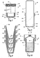
- FIG. 1 is a side elevation view of a gravity feed paint sprayer with a novel fluid supply cup according to the present invention having a container with an integral liner.
- FIG. 2 is a side-sectional view of the fluid supply cup of the present invention.
- FIG. 3 is a side-sectional view of the fluid supply cup before the integral liner has been folded into the container.
- FIG. 4 is a side sectional view of the fluid supply cup before paint is flowing into the paint sprayer.
- FIG. 5 is a side sectional view of the fluid supply cup wherein the liner is collapsing as paint is flowing into the paint sprayer.
- FIG. 6 is a side section view of an alternative embodiment of the present invention, wherein the liner is adhered to the container.
- FIG. 7 is a side sectional view of the fluid supply cup with a storage lid.
- FIG. 8 is a side sectional view of the fluid supply cup with a lid for engaging with an adapter of the paint sprayer.
- FIG.9 is a side sectional view of an alternative embodiment of the present invention, wherein the walls of the fluid supply cup are slanted to permit stacking.
- FIG. 10 is a side section view of the fluid supply cup with the lid for engaging with an adapter, wherein the adapter has not been engaged with the lid.
-
- Referring to FIG. 1, a
fluid supply cup 10 is shown for feeding fluid to afluid applicator 2. The novelfluid supply cup 10 includes aflexible liner 14 integral with acontainer 12 having an opening 16 (best shown in FIG. 2) and avent 18. In one embodiment,fluid supply cup 10 is for feeding fluid to a sprayer. In a preferred embodiment,fluid supply cup 10 is a paint cup for feeding paint to apaint sprayer 2; therefore the present invention will be described for a paint sprayer, such as a gravity feed paint sprayer for use in applyingpaint 1 to coat substrate surfaces. In one embodiment,paint sprayer 2 is used in the automotive refinishing market, such as automobile body shops, for repainting automobiles.Paint cup 10 of the present invention is easy for an operator to install and is inexpensive to manufacture, saving the operators both time and money. - Although
fluid supply cup 10 is described herein as a paint cup, it alternatively can be used for supplying other flowable fluids, such as beverages, foods, or condiments, for example ketchup, gasoline, petrochemicals and hydrocarbons, water, water-based solutions, solvent-based solutions, emulsions, and adhesives. The fluid being supplied must be compatible withfluid supply cup 10 and should be applied in a similar manner as paint frompaint cup 10. - A
paint sprayer 2 is shown in FIG. 1 and includes abody 3, anozzle assembly 4 secured to afront end 5 ofbody 3, and ahandle 6 depending from a rear end 7 ofbody 3. Atrigger 8 is pivotally secured tobody 3 for the manual actuation ofsprayer 2. A top mounted, gravityfeed paint cup 10 is mounted tobody 3 via anadapter 22 nearfront end 5 for feeding paint tonozzle assembly 4. Anair connector 9 is connected to an air hose (not shown) for the delivery of pressurized air tonozzle assembly 4, wherein the delivery of pressurized air is controlled bytrigger 8. - Compressed air from
connector 9 is delivered through an internal passage (not shown) tonozzle assembly 4 and the compressed air acts to atomize paint and deliver it throughnozzle assembly 4 to spraypaint 1 about aspray axis 11.Paint 1 is delivered tonozzle assembly 4 via gravity frompaint cup 10. The level ofpaint 1 inpaint cup 10 must be higher than thesprayer connection channel 13, or elsepaint 1 will not feed via gravity to thenozzle assembly 4, a condition known as starvation. - Turning to FIGS. 1 and 2, the novel and improved
paint cup 10 of the present invention provides an inexpensive, easy to use disposable container for the delivery ofpaint 1 to sprayer 2.Novel paint cup 10 includes acontainer 12 having anopening 16, best seen in FIG. 2, a,vent 18, and aflexible liner 14 integral withcontainer 12. In one embodiment, shown in FIG. 1,liner 14 is integrally formed withcontainer 12 atjoint 20 near opening 16.Paint 1 is loaded intoliner 14 andcontainer 12 is engaged withsprayer 2 so that thepaint 1 can be fed tonozzle assembly 4. - In one embodiment, best seen in FIG. 2,
container 12 includes a generallycylindrical side wall 24 having a generally openfirst end 26 defining opening 16 intocontainer 12 and abase wall 30 at asecond end 28, whereinside wall 24 andbase wall 30 surround aninterior 32 ofcontainer 12.Side wall 24 includes aside interior surface 34 andbase wall 30 includes abase interior surface 36. In one embodiment,vent 18 is included generally atsecond end 28, such as inbase wall 30, shown in FIG. 2.Vent 18 allows air to flow into theinterior 32 ofcontainer 12, providing vacuum relief so thatliner 14 may collapse (described below). In one embodiment,side wall 24c ofcontainer 12c is generally frusto-conical in shape so thatside wall 24c is slanted slightly, as shown in FIG. 9, so that a plurality ofpaint cups 10c can be stacked for easy storage and dispensation. - The walls of
container 12, such aswalls flexible liner 14.Walls walls walls container 12. -
Side wall 24 can includegraduations 38 indicating the level ofpaint 1 inpaint cup 10.Graduations 38 can act as proportional indicators to indicate the levels of one or more fluids that should be added to paintcup 10 to provide a predetermined ratio between the liquids. For example, a certain amount of a'base paint color can be mixed with tinting additives at a predetermined ratio to match a desired color for an automobile. -
Container 12 also includes a means for connection tosprayer 2. In one embodiment, shown in FIG. 4, the means for connection is threading 40 atfirst end 26 which engages directly withadapter 22 via adapter threading 42 so thatpaint cup 10 is releasably engageable withsprayer 2. The means for connection could also be a bayonet connection (not shown), or a snap engagement (not shown) betweencontainer 12 andadapter 22. Alternatively, the connection betweencontainer 12 andadapter 22b can be via alid 44, see FIG. 8, whereincontainer 12 can be connected tolid 44 with threading 40 engaging with lid threading 45, andlid 44 can be connected toadapter 22b via threading 46. -
Container 12 can engage withlid 44 andlid 44 can engage withadapter 22b by other connection means than a threaded connection, such as a bayonet connection, a snap engagement, or a self-locking taper engagement between the inlet connection and the container (not shown). Novel self-locking tapered connections are described in more detail in the commonly assigned, co-pending patent application with Attorney Docket # 14115 filed contemporaneously herewith, the disclosure of which is incorporated herein by reference. - In one embodiment,
lid 44 keepspaint cup 10 sealed untillid 44 is engaged withadapter 22. In this embodiment, shown in FIG. 10,lid 44 includes a perforable membrane 47 which is broken whenadapter 22 is engaged withlid 44, shown in FIG. 8. Aftercontainer 12 has been engaged withlid 44,paint 1 is sealed withinpaint cup 10 because air, water vapor, and other materials cannot pass through membrane 47. - It is important that the means for connection create a tight hermetic seal between
container 12 andadapter 22 or betweencontainer 12 andlid 44 and betweenlid 44 andadapter 22 so thatpaint cup 10 is water tight and air tight during operation ofsprayer 2 to prevent the escape of solvents, causing premature drying ofpaint 1 and the formation of a skin layer. Also, water can degrade the quality ofpaint 1, causing contamination or discoloration of the paint. - In one embodiment,
container 12 can have an interior volume of between about 8 fluid ounces and about 2.5 gallons, preferably between about 16 fluid ounces and about one liter. A one liter generallycylindrical container 12 has a length of about 4 inches and a diameter of about 6 inches. However,container 12 can have different proportions or geometry. Preferably, the size and shape ofcontainer 12 is conducive to the automobile refinishing industry so thatsprayer 2 and paintcup 10 are not unwieldy or overly heavy for an operator to handle. - Preferably,
container 12 is made from a translucent material so that the level ofpaint 1 can be seen throughcontainer 12.Container 12 should also be relatively durable and resistant to collapsing, be made from a relatively inexpensive material and be inexpensive to manufacture so thatcontainer 12 can be disposable, and be made from a material that is substantially unreactive, preferably unreactive to the fluid influid supply cup 10. In one embodiment,container 12 is made from a molded plastic, such as polyethylene or polypropylene. In a preferred embodiment,container 12 is molded from low-density polyethylene. - Turning to FIG. 5,
flexible liner 14 is located withininterior 32 ofcontainer 12.Liner 14 is thin and flexible so that it is capable of collapsing aspaint 1 flows out ofpaint cup 10 and intosprayer 2 while still preventing the inflow of air intoliner 14. Aspaint 1 flows out of liner 14 a partial vacuum is formed withinliner 14 due to fluid displacement. Becauseliner 14 is flexible and vent 18 allows air to flow intointerior 32 of container, atmospheric pressure offsets the vacuum formed inliner 14, and causesliner 14 to collapse, as shown in FIG. 5. - The thickness of
liner 14 is relatively thinner than the thickness ofwalls container 12.Liner 14 should be thin enough so that it is flexible, softer thancontainer 12, pliable, and insertable intointerior 32 ofcontainer 12. In one embodiment, the thickness ofliner 14 is between about 0.004 inches and about 0.015 inches, and preferably between about 0.005 inches and about 0.01 inches. -
Flexible liner 14 is integral withcontainer 12. In one embodiment,liner 14 is integrally molded withcontainer 12 so that they are formed continuously, best shown in FIG. 2, such as by injection blow moldingflexible liner 14 andcontainer 12 in the same process as described below. Preferably,liner 14 is integral withcontainer 12 at joint 20 atfirst end 26 around opening 16, as shown in FIGS. 2 and 3, so thatliner 14 will be easily invertable intointerior 32 ofcontainer 12. - In another embodiment, shown in FIG. 6,
liner 14b andcontainer 12b are molded or formed separately and adhered to each other to formpaint cup 10b.Liner 14b can be adhered or attached tocontainer 12b via, for example, adhesives, plastic weldment, sonic weldment, molecular diffusion, or other methods of fusing plastic. Preferably,liner 14b is adhered tocontainer 12b at joint 20b near opening 16b. In one embodiment, shown in FIG. 6,liner 14b includes a portion 48 that extends past opening 16b to cover threading 40b so that whencontainer 12b is threadingly engaged withadapter 22, so that portion 48 ofliner 14b will act as an extra seal betweencontainer 12b andadapter 22 to prevent leakage ofpaint 1. - In a preferred embodiment, shown in FIG. 2,
liner 14 substantially conforms tointerior surfaces container 12 whenliner 14 is not collapsed, still more preferably so that there is full geometric conformity betweeninterior surfaces liner 14. Conformity ofliner 14 preferred so that the level ofpaint 1 inliner 14 can most accurately be measured withgraduations 38. Accurate indication of fluid level is particularly important during mixing of multiple fluids in predetermined ratios. - As with
container 12,flexible liner 14 is preferably made from a translucent material so that the paint level can be seen. Liner should also be made from a material that can be pliable and foldable, and that is unreactive with the fluid influid supply cup 10. Further, the material ofliner 14 should be inexpensive, andliner 14 should be inexpensive to manufacture. In one embodiment,liner 14 is made from a moldable plastic, such as polyethylene or polypropylene. In a preferred embodiment,liner 14 is molded from low density polyethylene. - Advantageously, in order to connect
paint cup 10 withsprayer 2, the operator simply has to engagecontainer 12 withadapter 22, or withlid 44 and then engagelid 44 withadapter 22b as in FIG. 8, which requires very little time or effort on the part of the operator. The easy assembly ofpaint cup 10 offers a significant savings of time and effort on the part of operators over traditional paint cups, which require significant assembly of several complicated parts. Further,paint cup 10 is inexpensive to manufacture so that it can be disposable without being overly expensive. - Returning to FIG. 1,
adapter 22 provides a connection betweenpaint cup 10 andsprayer 2 and provides a path forpaint 1 to flow frompaint cup 10 intosprayer body 3.Adapter 22 can engage directly withcontainer 12 at opening 16, such as between container threading 40 and adapter threading 42, oradapter 22 can engage with alid 44. Preferably;adapter 22 is a mass produced machined adapter and the connection betweenadapter 22 andsprayer body 3 is a conventional connection, such as threaded engagement between threading 49 onadapter 22 and sprayer threading 50, so that adapter may be releasably connected toseveral sprayers 2. In one embodiment, adapter also includes a filter (not shown) to filter impurities, such as dust or other particulates, from flowing intosprayer 2 so that the impurities will not be applied to the surface being painted. - Although
adapter 22 is shown as being one piece, it is envisioned thatadapter 22 can have other configurations, such as an adjustable adapter that allows the orientation ofcontainer 12 to be changed to ensure thatpaint 1 will flow intosprayer 2. A novel adjustable adapter is disclosed in the commonly assigned, co-pending patent application with Attorney Docket #14114 filed contemporaneously herewith, the disclosure of which is incorporated herein by reference. - Turning to FIG. 7, in another embodiment a
storage lid 52 is provided for coveringpaint cup 10 when painting is completed or temporarily stopped. The exact amount ofpaint 1 required may not be easy to determine, and there is frequently left overpaint 1. In some cases, it may be desirable to store a particular color ofpaint 1 for later use, such as for touch-ups of a popular automotive paint color.Storage lid 52 includes a means for connection to container, such as storage lid threading 54 that engages with container threading 40, to coveropening 16 and provide a tight, hermetic seal withpaint cup 10, so that left overpaint 1 can be stored easily. Somepaints 1 have a shelf life of up to about 3 days or more. Preferably, the top 56 ofstorage lid 52 generally complements thebase wall 30 ofcontainer 12 so that multiple covered paint cups 10 can be stacked. - Alternatively, after application of
paint 1, it may be desirable to discard left-over paint while preventing spillage ofpaint 1 frompaint cups 10. Because some paints include solvents or other components that are undesirable to allow to spill, the tight seal betweencontainer 12 andstorage lid 52 allows for sanitary disposal of left-overpaint 1. - New and
improved paint cup 10 is made by a novel method including the steps of molding a container, such aspaint cup 10 shown in FIG. 2, having a vented thick-walled portion and an integral flexible thin-walled liner, and folding the thin-walled liner into the thick-walled portion. In one embodiment, shown in FIG. 2, the thick-walled portion iscontainer 12 and the thin-walled liner isflexible liner 14. - Molding of
liner 14 andcontainer 12 are preferably done by a process whereinliner 14 andcontainer 12 are integrally formed so thatliner 14 andcontainer 12 are molded as a single piece. In one method, the molding process forms a generally closed container, such as the generally closed cylinder shown in FIG. 3, wherein the thickness of the walls of the cylinder abruptly diminishes along the length of the cylinder between thin-walled liner 14 and thick-walled container 12. - In one method, molding of
liner 14 andcontainer 12 comprises a two-step injection blow molding process. The two-step process requires precision control of a parison used to mold bothliner 14 andcontainer 12.Liner 14 injection molded in a first step at a relatively low pressure, wherein the temperature, pressure, and other molding conditions should be tightly controlled. After injection blow molding ofliner 14, the pressure is increased to a relatively high pressure, to injection blowmold container 12. - Injection blow molding of
liner 14 andcontainer 12 is accomplished through a blow hole formed at the base ofcontainer 12. In a preferred embodiment ofcontainer 12,hole 18 acts as the'blow hole during the molding process. Thesame hole 18 can be used to vent air into the interior 32 ofcontainer 12 during subsequent use ofpaint cup 10. -
Liner 14 andcontainer 12 can be molded by other means, such as injection molding, rotational molding, suction molding, or extrusion molding. Injection blow molding is preferred because it is an inexpensive process. Alternatively, molding ofliner 14 andcontainer 12 can be separate and liner andcontainer 12 can be made integral by adheringliner 14 to container. - After
liner 14 andcontainer 12 have been molded and are integral with each other, as in FIG. 3,liner 14 is folded intocontainer 12 to form a linedpaint cup 10, shown in FIG. 2. Folding ofliner 14 intocontainer 12 can be done mechanically, such as by air pressure, applied toliner 14 to force it into the interior 32 ofcontainer 12, or by forming a partial vacuum ininterior 32 ofcontainer 12 so thatliner 14 is drawn intocontainer 12. In a preferred method,liner 14 is mechanically inserted intocontainer 12 with assistance from a partial vacuum formed in interior 32 throughvent 18. - Preferably, folding
liner 14 incontainer 12 includes substantially conformingliner 14 tointerior surfaces container 12. In one method, conformingliner 14 tosurfaces liner 14 so that there is full geometric conformity betweenliner 14 andinterior surfaces - A novel method of applying a fluid comprises the steps of providing a
flexible liner 14 integral with acontainer 12 having anopening 16 and avent 18, loading fluid, such aspaint 1, intoliner 14, engagingcontainer 12 with a fluid applicator, flowing the fluid out ofliner 14 and into thefluid applicator 2, collapsingliner 14, and flowing the fluid out of the fluid applicator. - In one method, the flowing step comprises spraying the fluid out of
sprayer 2 and in another method,sprayer 2 is a paint sprayer for sprayingpaint 1 onto a surface, such as the body of an automobile. - The loading step includes loading paint into
paint cup 10. The loading step can also comprise loading paint intoliner 14 followed by loading a second fluid, such as another paint, tinting additives, or solvents, in predetermined ratios to create paint having a desired color. - The step of engaging
container 12 withsprayer 2 can be accomplished by engagingcontainer 12 directly with anadapter 22 connected tosprayer 2, shown in FIGS. 1 and 4, or by engagingcontainer 12 with alid 44 followed by engaginglid 44 withadapter 22b, as shown in FIG. 8. - The collapsing step includes collapsing
liner 14 due to a partial vacuum formed aspaint 1 is drawn out ofliner 14 and intosprayer 2. - The inventive method can also include the step of covering
container 12 with astorage lid 52 for the storage or disposal of left-overpaint 1 inpaint cup 10. - The present invention provides an inexpensive and disposable fluid supply cup that requires little assembly on the part of an operator and that can be easily stored and disposed. The novel fluid supply cup comprises a flexible liner integral with a container having an opening and a vent. A novel method of manufacturing a lined fluid supply container comprises the steps of molding a container having a vented thick-walled portion and an integral thin-walled liner, and folding the thin-walled liner into the thick walled portion. Also, a novel method of applying a fluid is provided comprising the steps of providing a flexible liner integral with a container having an opening and a vent, loading fluid into the liner, engaging the container with a fluid applicator, flowing the fluid out of the liner and into the fluid applicator, collapsing the liner, and flowing the fluid out of the fluid applicator.
- While the foregoing written description of the invention enables one of ordinary skill to make and use what is considered presently to be the best mode thereof, those of ordinary skill will understand and appreciate the existence of variations, combinations, and equivalents of the specific exemplary embodiments and methods herein. The invention should therefore not be limited by the above described embodiments and methods, but by all embodiments and methods within the scope and spirit of the invention.
Claims (18)
- A fluid supply cup comprising a flexible liner integral with a container having an opening and a vent.
- A fluid supply cup according to claim 1, wherein said flexible liner and said container are integrally molded.
- A fluid supply cup according to claim 1 or 2, wherein said container further comprises an interior surface, wherein said flexible liner conforms to said interior surface.
- A fluid supply cup according to one of the preceding claims, wherein said container further comprises slanted side walls for stacking.
- A fluid supply cup according to one of the preceding claims, wherein said container is engageable with a fluid applicator.
- A fluid supply cup according to one of the preceding claims, further comprising a lid for covering said container.
- A fluid supply cup according to claim 6, wherein said lid includes a perforable membrane.
- A method of manufacturing a lined container comprising the steps of:molding a container having a vented thick-walled portion and an integral flexible thin-walled liner; andfolding said thin-walled liner into said thick-walled portion.
- A method according to claim 8, wherein said molding step includes integrally molding said thick-walled portion and said thin-walled liner as a single piece.
- A method according to claim 8 or 9, wherein said container is molded by injection blow molding.
- A method according to claim 9 or 10, wherein said molding comprises the steps of:blow molding said thin-walled liner at a first pressure; andblow molding said thick-walled portion at a second pressure higher than said first pressure.
- A method according to one of claims 8 to 11, wherein said folding step comprises mannually inserting said thin-walled liner into said thick-walled portion.
- A method according to one of claims 8 to 12, wherein said folding step comprises creating a partial vacuum in said container to draw said thin-walled liner into said container.
- A method of applying a fluid comprising the steps of:providing a flexible liner integral with a container having an opening and a vent;loading fluid into said liner;engaging said container with a fluid applicator;flowing the fluid out of said liner and into said fluid applicator;collapsing said liner; andflowing the fluid out of said fluid applicator.
- A method according to claim 14, wherein said fluid applicator is a sprayer and wherein said flowing step comprises spraying the fluid out of said sprayer.
- A method according to claim 14 or 15, wherein said engaging step comprises engaging said container with'an adapter and engaging said adapter with said fluid applicator.
- A method according to claim 14 or 15, wherein said engaging step comprises engaging said container with a lid, engaging said lid with an adapter, and engaging said adapter with said fluid applicator.
- A method according to one of claims 14 to 17, wherein said loading step comprises loading fluids in a predetermined ratio.
Applications Claiming Priority (2)
| Application Number | Priority Date | Filing Date | Title |
|---|---|---|---|
| US458478 | 1999-12-09 | ||
| US10/458,478 US6945429B2 (en) | 2003-06-10 | 2003-06-10 | Disposable paint cup attachment system for gravity-feed paint sprayer |
Publications (2)
| Publication Number | Publication Date |
|---|---|
| EP1486258A2 true EP1486258A2 (en) | 2004-12-15 |
| EP1486258A3 EP1486258A3 (en) | 2006-02-15 |
Family
ID=33299640
Family Applications (1)
| Application Number | Title | Priority Date | Filing Date |
|---|---|---|---|
| EP04009885A Withdrawn EP1486258A3 (en) | 2003-06-10 | 2004-04-26 | Disposable paint cup attachment system for gravity-feed paint sprayer |
Country Status (6)
| Country | Link |
|---|---|
| US (1) | US6945429B2 (en) |
| EP (1) | EP1486258A3 (en) |
| CA (1) | CA2466801C (en) |
| MX (1) | MXPA04005599A (en) |
| NZ (1) | NZ533386A (en) |
| ZA (1) | ZA200403736B (en) |
Cited By (2)
| Publication number | Priority date | Publication date | Assignee | Title |
|---|---|---|---|---|
| GB2439166A (en) * | 2006-04-26 | 2007-12-19 | Wagner Spray Tech Corp | Hand held hopper sprayer |
| WO2011083055A1 (en) | 2010-01-05 | 2011-07-14 | Novo Nordisk A/S | Method for forming collapsible reservoir |
Families Citing this family (89)
| Publication number | Priority date | Publication date | Assignee | Title |
|---|---|---|---|---|
| US6820824B1 (en) | 1998-01-14 | 2004-11-23 | 3M Innovative Properties Company | Apparatus for spraying liquids, disposable containers and liners suitable for use therewith |
| FR2859118B1 (en) * | 2003-08-26 | 2007-03-09 | Michel Camilleri | DISPOSABLE BUCKET TO BE MOUNTED ON A GUN FOR THE PREPARATION, APPLICATION AND PRESERVATION OF A PAINT |
| US7665672B2 (en) | 2004-01-16 | 2010-02-23 | Illinois Tool Works Inc. | Antistatic paint cup |
| US7165732B2 (en) | 2004-01-16 | 2007-01-23 | Illinois Tool Works Inc. | Adapter assembly for a fluid supply assembly |
| US7086549B2 (en) | 2004-01-16 | 2006-08-08 | Illinois Tool Works Inc. | Fluid supply assembly |
| US7766250B2 (en) | 2004-06-01 | 2010-08-03 | Illinois Tool Works Inc. | Antistatic paint cup |
| US7757972B2 (en) | 2004-06-03 | 2010-07-20 | Illinois Tool Works Inc. | Conversion adapter for a fluid supply assembly |
| US7353964B2 (en) | 2004-06-10 | 2008-04-08 | Illinois Tool Works Inc. | Fluid supply assembly |
| PL2450108T3 (en) | 2004-12-16 | 2017-04-28 | Saint-Gobain Abrasives, Inc. | Liquid supply cup and liner assembly for spray guns |
| DE102005000056A1 (en) * | 2005-05-10 | 2006-11-16 | Hilti Ag | cartridge |
| US20070095943A1 (en) * | 2005-10-28 | 2007-05-03 | Turnbull William N | Liquid reservoir, and kit, spray assembly and method using same |
| EP2029285B1 (en) | 2006-06-20 | 2012-11-21 | Saint-Gobain Abrasives, Inc. | Liquid supply assembly |
| US11040360B2 (en) * | 2006-06-20 | 2021-06-22 | Saint-Gobain Abrasives, Inc. | Liquid supply assembly |
| US20080050170A1 (en) * | 2006-08-22 | 2008-02-28 | Mondloch Steven J | Pistonless Apparatus for Dispensing Liquified Material |
| US20080116685A1 (en) * | 2006-11-17 | 2008-05-22 | Chia Chung Precision Industrial Co., Ltd. | Helical structure for connecting spray gun and paint cup |
| EP1930084B1 (en) | 2006-12-05 | 2009-06-03 | SATA GmbH & Co. KG | Vent for the gravity cup of a paint spray gun |
| US20080230630A1 (en) * | 2007-03-08 | 2008-09-25 | Illinois Tool Works Inc. | Color matching system and method |
| NL1034895C2 (en) * | 2008-01-08 | 2009-07-13 | Dispensing Technologies Bv | Composite container and method for manufacturing thereof. |
| WO2009090273A1 (en) * | 2008-01-16 | 2009-07-23 | Boss Auto Import, S.A. | Improved disposable double-wall cup having a flexible inner surface and cover for spray guns |
| US9327301B2 (en) | 2008-03-12 | 2016-05-03 | Jeffrey D. Fox | Disposable spray gun cartridge |
| US7815132B2 (en) * | 2008-08-12 | 2010-10-19 | Illinois Tool Works Inc. | Method for preventing voltage from escaping fluid interface for water base gravity feed applicators |
| DE202008014389U1 (en) | 2008-10-29 | 2010-04-08 | Sata Gmbh & Co. Kg | Gravity cup for a paint spray gun |
| WO2010084140A1 (en) | 2009-01-23 | 2010-07-29 | Akzo Nobel Coatings International B.V. | Packaging for two or more fluids |
| TW201036707A (en) * | 2009-04-01 | 2010-10-16 | Victor Air Tools Co Ltd | Feeding structure of spray device |
| DE102009032399A1 (en) | 2009-07-08 | 2011-01-13 | Sata Gmbh & Co. Kg | Spray Gun |
| US20110024461A1 (en) * | 2009-07-30 | 2011-02-03 | Edward Kilduff | Aeration pouring device |
| DE202010007355U1 (en) | 2010-05-28 | 2011-10-20 | Sata Gmbh & Co. Kg | Nozzle head for a spraying device |
| US10286414B2 (en) | 2010-07-12 | 2019-05-14 | Carlisle Fluid Technologies, Inc. | Liquid supply container for a spray coating device |
| US9333519B2 (en) | 2010-12-02 | 2016-05-10 | Sata Gmbh & Co. Kg | Spray gun and accessories |
| EP2704847B1 (en) | 2011-05-06 | 2019-11-27 | Saint-Gobain Abrasives, Inc | Paint cup assembly with an outlet valve |
| WO2013003592A2 (en) | 2011-06-30 | 2013-01-03 | Saint-Gobain Abrasives, Inc. | Paint cup assembly |
| JP6189834B2 (en) | 2011-06-30 | 2017-08-30 | サタ ゲーエムベーハー アンド カンパニー カーゲー | Spray gun, spray medium guide unit and method for removal or removal |
| WO2013063231A1 (en) * | 2011-10-27 | 2013-05-02 | Graco Minnesota Inc. | Sprayer fluid supply with collapsible liner |
| EP2797697B1 (en) | 2011-12-30 | 2020-11-04 | Saint-Gobain Abrasives, Inc. | Convertible paint cup assembly with air inlet valve |
| US9352343B2 (en) | 2013-01-22 | 2016-05-31 | Carlisle Fluid Technologies, Inc. | Liquid supply system for a gravity feed spray device |
| CA155474S (en) | 2013-09-27 | 2015-08-27 | Sata Gmbh & Co Kg | Spray gun |
| JP6002957B2 (en) * | 2013-10-29 | 2016-10-05 | 兵神装備株式会社 | Discharge system |
| EP3077124B1 (en) | 2013-12-05 | 2020-12-23 | 3M Innovative Properties Company | Container for a spraying device |
| DE202013105779U1 (en) | 2013-12-18 | 2015-03-19 | Sata Gmbh & Co. Kg | Air nozzle termination for a paint spray gun |
| USD800505S1 (en) * | 2014-05-19 | 2017-10-24 | Troy Bowen | Drinking vessel |
| CA159961S (en) | 2014-07-31 | 2015-07-17 | Sata Gmbh & Co Kg | Spray gun |
| CN110560285B (en) | 2014-07-31 | 2021-05-18 | 萨塔有限两合公司 | Spray gun and method for manufacturing same |
| USD758537S1 (en) | 2014-07-31 | 2016-06-07 | Sata Gmbh & Co. Kg | Paint spray gun rear portion |
| USD768820S1 (en) | 2014-09-03 | 2016-10-11 | Sata Gmbh & Co. Kg | Paint spray gun with pattern |
| US10589309B2 (en) | 2015-02-20 | 2020-03-17 | Carlisle Fluid Technologies, Inc. | Sprayer adapter |
| CN107427851B (en) * | 2015-03-05 | 2020-06-30 | 涂层国外知识产权有限公司 | Spray gun with hollow needle to ensure gravity feed and method of using same |
| US9796492B2 (en) | 2015-03-12 | 2017-10-24 | Graco Minnesota Inc. | Manual check valve for priming a collapsible fluid liner for a sprayer |
| DE102015006484A1 (en) | 2015-05-22 | 2016-11-24 | Sata Gmbh & Co. Kg | Nozzle arrangement for a spray gun, in particular paint spray gun and spray gun, in particular paint spray gun |
| CN107847956B (en) | 2015-07-08 | 2021-08-10 | 3M创新有限公司 | Spray gun cup, receiver and method of use |
| USD792556S1 (en) | 2015-07-08 | 2017-07-18 | 3M Innovative Properties Company | Spray gun cup receptacle |
| DE102015016474A1 (en) | 2015-12-21 | 2017-06-22 | Sata Gmbh & Co. Kg | Air cap and nozzle assembly for a spray gun and spray gun |
| PL3402604T3 (en) | 2016-01-15 | 2021-07-19 | 3M Innovative Properties Company | Wide-mouthed fluid connector for hand-held spray guns |
| CA3011437C (en) | 2016-01-15 | 2024-02-13 | 3M Innovative Properties Company | Spray gun cups, receptacles, lids, and methods of use |
| US11413636B2 (en) | 2016-01-15 | 2022-08-16 | 3M Innovative Properties Company | Connector system for hand-held spray guns |
| WO2017123707A1 (en) | 2016-01-15 | 2017-07-20 | 3M Innovative Properties Company | Modular spray gun lid assemblies and methods of design and use |
| USD793531S1 (en) | 2016-03-24 | 2017-08-01 | 3M Innovative Properties Company | Spray gun cup receptacle |
| USD811525S1 (en) | 2016-03-24 | 2018-02-27 | 3M Innovative Properties Company | Retention collar for spray gun cup |
| US10689165B2 (en) | 2016-01-15 | 2020-06-23 | 3M Innovative Properties Company | Reservoir systems for hand-held spray guns and methods of use |
| JP2019508229A (en) | 2016-01-15 | 2019-03-28 | スリーエム イノベイティブ プロパティズ カンパニー | Spray gun cup, container and method of use |
| USD793530S1 (en) | 2016-03-24 | 2017-08-01 | 3M Innovative Properties Company | Lid for spray gun cup |
| CN205966208U (en) | 2016-08-19 | 2017-02-22 | 萨塔有限两合公司 | Hood subassembly and spray gun |
| CN205995666U (en) | 2016-08-19 | 2017-03-08 | 萨塔有限两合公司 | Spray gun and its trigger |
| USD810871S1 (en) | 2016-12-12 | 2018-02-20 | 3M Innovative Properties Company | Shaker core |
| USD810870S1 (en) | 2016-12-12 | 2018-02-20 | 3M Innovative Properties Company | Shaker core |
| USD813985S1 (en) | 2016-12-12 | 2018-03-27 | 3M Innovative Properties Company | Spray gun liquid containment device |
| USD804614S1 (en) | 2016-12-12 | 2017-12-05 | 3M Innovative Properties Company | Adaptor for securing liquid containment device to spray gun |
| USD815248S1 (en) | 2016-12-12 | 2018-04-10 | 3M Innovative Properties Company | Spray gun liquid containment device |
| USD810868S1 (en) | 2016-12-12 | 2018-02-20 | 3M Innovative Properties Company | Spray gun liquid containment device |
| USD810862S1 (en) | 2016-12-12 | 2018-02-20 | 3M Innovative Properties Company | Spray gun liquid containment device |
| USD833571S1 (en) | 2016-12-12 | 2018-11-13 | 3M Innovative Properties Company | Spray gun |
| USD810863S1 (en) | 2016-12-12 | 2018-02-20 | 3M Innovative Properties Company | Spray gun liquid containment device |
| USD817443S1 (en) | 2016-12-12 | 2018-05-08 | 3M Innovative Properties Company | Spray gun liquid containment device |
| USD810235S1 (en) | 2016-12-12 | 2018-02-13 | 3M Innovative Properties Company | Spray gun liquid containment device |
| USD810869S1 (en) | 2016-12-12 | 2018-02-20 | 3M Innovative Properties Company | Spray gun liquid containment device |
| USD810872S1 (en) | 2016-12-12 | 2018-02-20 | 3M Innovative Properties Company | Shaker core |
| USD810866S1 (en) | 2016-12-12 | 2018-02-20 | 3M Innovative Properties Company | Spray gun liquid containment device |
| USD810865S1 (en) | 2016-12-12 | 2018-02-20 | 3M Innovative Properties Company | Spray gun liquid containment device |
| USD804613S1 (en) | 2016-12-12 | 2017-12-05 | 3M Innovative Properties Company | Spray gun nozzle |
| USD810867S1 (en) | 2016-12-12 | 2018-02-20 | 3M Innovative Properties Company | Spray gun liquid containment device |
| USD810864S1 (en) | 2016-12-12 | 2018-02-20 | 3M Innovative Properties Company | Spray gun liquid containment device |
| USD812716S1 (en) | 2016-12-12 | 2018-03-13 | 3M Innovative Properties Company | Liquid containment device plug |
| US10710105B2 (en) * | 2017-10-31 | 2020-07-14 | Zhejiang Rongpeng Air Tools Co., Ltd. | Disposable cleaning-free paint pot |
| WO2018184636A2 (en) | 2018-08-01 | 2018-10-11 | Sata Gmbh & Co. Kg | Set of nozzles for a spray gun, spray gun system, method for embodying a nozzle module, method for seelcting a nozzle module from a set of nozzles for a paint job, selection system and computer program product |
| DE102018118737A1 (en) | 2018-08-01 | 2020-02-06 | Sata Gmbh & Co. Kg | Nozzle for a spray gun, nozzle set for a spray gun, spray guns and method for producing a nozzle for a spray gun |
| DE102018118738A1 (en) | 2018-08-01 | 2020-02-06 | Sata Gmbh & Co. Kg | Base body for a spray gun, spray guns, spray gun set, method for producing a base body for a spray gun and method for converting a spray gun |
| USD918340S1 (en) * | 2019-05-01 | 2021-05-04 | Tony ZHENG | Paint cup |
| US20220234062A1 (en) | 2019-05-31 | 2022-07-28 | Graco Minnesota Inc. | Handheld fluid sprayer |
| US20210220850A1 (en) * | 2020-01-22 | 2021-07-22 | W.M. Barr & Company, Inc. | Automotive spray gun bottle and adapter |
| CN117813166A (en) * | 2021-06-25 | 2024-04-02 | W·M·巴尔公司 | Spray gun bottle and adapter for vehicle |
Citations (5)
| Publication number | Priority date | Publication date | Assignee | Title |
|---|---|---|---|---|
| US631102A (en) | 1897-04-19 | 1899-08-15 | Ethel M Bigsby | Garment-hanger. |
| US1386102A (en) | 1919-05-19 | 1921-08-02 | Charles H Fuller | Lifeboat-derrick |
| US5582350A (en) | 1994-04-19 | 1996-12-10 | Ransburg Corporation | Hand held paint spray gun with top mounted paint cup |
| US5816501A (en) | 1996-12-16 | 1998-10-06 | Ransburg Corporation | Disposable paint container liner and method |
| WO2002072276A1 (en) | 2001-03-14 | 2002-09-19 | 3M Innovative Properties Company | Liquid sample reservoir suitable for use with a spraying apparatus |
Family Cites Families (12)
| Publication number | Priority date | Publication date | Assignee | Title |
|---|---|---|---|---|
| FR2081244A1 (en) * | 1970-03-23 | 1971-12-03 | Bouet Bernard | |
| GB1472178A (en) * | 1973-08-10 | 1977-05-04 | Meshberg P | Liquid dispenser using a non-venting pump and a collapsible bag |
| US4151929A (en) * | 1976-07-09 | 1979-05-01 | Sapien Sisto V | Plastic liner with collar for a paint receptacle |
| US4886212A (en) * | 1985-03-20 | 1989-12-12 | Turbo Tek Enterprises, Inc. | Spraying device having controlled additive fluid feed and a telescoping spray tube assembly |
| FR2646408B1 (en) * | 1989-04-28 | 1991-08-30 | Sofab | PACKAGING WITH INTEGRATED DISPENSER |
| US5344045A (en) * | 1990-12-17 | 1994-09-06 | The Coca-Cola Company | Liquid container system |
| US5242085A (en) | 1990-12-17 | 1993-09-07 | The Coca-Cola Company | Liquid container system |
| US5301838A (en) | 1991-01-23 | 1994-04-12 | Continental Pet Technologies, Inc. | Multilayer bottle with separable inner layer and method for forming same |
| US6062430A (en) * | 1993-05-05 | 2000-05-16 | Ing. Erich Pfeiffer Gmbh | Dispensing container with variable volume compensation |
| DE19737964C1 (en) | 1997-08-30 | 1998-10-08 | Gaplast Gmbh | Cutting an interspace vent in the external wall of a flexibly-lined rigid vessel |
| US6536687B1 (en) * | 1999-08-16 | 2003-03-25 | 3M Innovative Properties Company | Mixing cup adapting assembly |
| US6588681B2 (en) * | 2001-07-09 | 2003-07-08 | 3M Innovative Properties Company | Liquid supply assembly |
-
2003
- 2003-06-10 US US10/458,478 patent/US6945429B2/en not_active Expired - Fee Related
-
2004
- 2004-04-26 EP EP04009885A patent/EP1486258A3/en not_active Withdrawn
- 2004-05-11 CA CA2466801A patent/CA2466801C/en not_active Expired - Fee Related
- 2004-05-14 ZA ZA200403736A patent/ZA200403736B/en unknown
- 2004-06-08 NZ NZ533386A patent/NZ533386A/en not_active IP Right Cessation
- 2004-06-09 MX MXPA04005599A patent/MXPA04005599A/en active IP Right Grant
Patent Citations (5)
| Publication number | Priority date | Publication date | Assignee | Title |
|---|---|---|---|---|
| US631102A (en) | 1897-04-19 | 1899-08-15 | Ethel M Bigsby | Garment-hanger. |
| US1386102A (en) | 1919-05-19 | 1921-08-02 | Charles H Fuller | Lifeboat-derrick |
| US5582350A (en) | 1994-04-19 | 1996-12-10 | Ransburg Corporation | Hand held paint spray gun with top mounted paint cup |
| US5816501A (en) | 1996-12-16 | 1998-10-06 | Ransburg Corporation | Disposable paint container liner and method |
| WO2002072276A1 (en) | 2001-03-14 | 2002-09-19 | 3M Innovative Properties Company | Liquid sample reservoir suitable for use with a spraying apparatus |
Cited By (6)
| Publication number | Priority date | Publication date | Assignee | Title |
|---|---|---|---|---|
| GB2439166A (en) * | 2006-04-26 | 2007-12-19 | Wagner Spray Tech Corp | Hand held hopper sprayer |
| US7731104B2 (en) | 2006-04-26 | 2010-06-08 | Wagner Spray Tech Corporation | Texture sprayer |
| US7861950B2 (en) | 2006-04-26 | 2011-01-04 | Wagner Spray Tech Corporation | Texture sprayer noise reducer |
| GB2439166B (en) * | 2006-04-26 | 2011-07-06 | Wagner Spray Tech Corp | Texture sprayer |
| US8210449B2 (en) | 2006-04-26 | 2012-07-03 | Wagner Spray Tech Corporation | Texture sprayer |
| WO2011083055A1 (en) | 2010-01-05 | 2011-07-14 | Novo Nordisk A/S | Method for forming collapsible reservoir |
Also Published As
| Publication number | Publication date |
|---|---|
| ZA200403736B (en) | 2005-07-04 |
| US20040251269A1 (en) | 2004-12-16 |
| CA2466801C (en) | 2011-07-26 |
| NZ533386A (en) | 2006-01-27 |
| CA2466801A1 (en) | 2004-12-10 |
| MXPA04005599A (en) | 2004-12-15 |
| US6945429B2 (en) | 2005-09-20 |
| EP1486258A3 (en) | 2006-02-15 |
Similar Documents
| Publication | Publication Date | Title |
|---|---|---|
| US6945429B2 (en) | Disposable paint cup attachment system for gravity-feed paint sprayer | |
| US7165732B2 (en) | Adapter assembly for a fluid supply assembly | |
| US7344040B2 (en) | Fluid supply assembly | |
| AU2008214148B2 (en) | Fluid supply assembly | |
| US7757972B2 (en) | Conversion adapter for a fluid supply assembly | |
| CA2564819C (en) | Adapter assembly and disposable lining for the fluid supply cup of a spray gun | |
| JPH07289956A (en) | Coating material spray gun | |
| AU2004202537A1 (en) | Disposable paint cup attachment system for gravity-feed paint sprayer | |
| AU2007200586B2 (en) | A fluid supply cup |
Legal Events
| Date | Code | Title | Description |
|---|---|---|---|
| PUAI | Public reference made under article 153(3) epc to a published international application that has entered the european phase |
Free format text: ORIGINAL CODE: 0009012 |
|
| AK | Designated contracting states |
Kind code of ref document: A2 Designated state(s): AT BE BG CH CY CZ DE DK EE ES FI FR GB GR HU IE IT LI LU MC NL PL PT RO SE SI SK TR |
|
| AX | Request for extension of the european patent |
Extension state: AL HR LT LV MK |
|
| PUAL | Search report despatched |
Free format text: ORIGINAL CODE: 0009013 |
|
| AK | Designated contracting states |
Kind code of ref document: A3 Designated state(s): AT BE BG CH CY CZ DE DK EE ES FI FR GB GR HU IE IT LI LU MC NL PL PT RO SE SI SK TR |
|
| AX | Request for extension of the european patent |
Extension state: AL HR LT LV MK |
|
| 17P | Request for examination filed |
Effective date: 20060616 |
|
| AKX | Designation fees paid |
Designated state(s): BE DE ES FR IT PT |
|
| 17Q | First examination report despatched |
Effective date: 20080417 |
|
| STAA | Information on the status of an ep patent application or granted ep patent |
Free format text: STATUS: THE APPLICATION IS DEEMED TO BE WITHDRAWN |
|
| 18D | Application deemed to be withdrawn |
Effective date: 20101103 |