EP1486386A2 - Electrical steering lock device for an automotive vehicle and related method - Google Patents
Electrical steering lock device for an automotive vehicle and related method Download PDFInfo
- Publication number
- EP1486386A2 EP1486386A2 EP20040013676 EP04013676A EP1486386A2 EP 1486386 A2 EP1486386 A2 EP 1486386A2 EP 20040013676 EP20040013676 EP 20040013676 EP 04013676 A EP04013676 A EP 04013676A EP 1486386 A2 EP1486386 A2 EP 1486386A2
- Authority
- EP
- European Patent Office
- Prior art keywords
- lock
- shaft
- steering
- groove
- lock groove
- Prior art date
- Legal status (The legal status is an assumption and is not a legal conclusion. Google has not performed a legal analysis and makes no representation as to the accuracy of the status listed.)
- Granted
Links
Images


Classifications
-
- B—PERFORMING OPERATIONS; TRANSPORTING
- B60—VEHICLES IN GENERAL
- B60R—VEHICLES, VEHICLE FITTINGS, OR VEHICLE PARTS, NOT OTHERWISE PROVIDED FOR
- B60R25/00—Fittings or systems for preventing or indicating unauthorised use or theft of vehicles
- B60R25/01—Fittings or systems for preventing or indicating unauthorised use or theft of vehicles operating on vehicle systems or fittings, e.g. on doors, seats or windscreens
- B60R25/02—Fittings or systems for preventing or indicating unauthorised use or theft of vehicles operating on vehicle systems or fittings, e.g. on doors, seats or windscreens operating on the steering mechanism
- B60R25/021—Fittings or systems for preventing or indicating unauthorised use or theft of vehicles operating on vehicle systems or fittings, e.g. on doors, seats or windscreens operating on the steering mechanism restraining movement of the steering column or steering wheel hub, e.g. restraining means controlled by ignition switch
- B60R25/0215—Fittings or systems for preventing or indicating unauthorised use or theft of vehicles operating on vehicle systems or fittings, e.g. on doors, seats or windscreens operating on the steering mechanism restraining movement of the steering column or steering wheel hub, e.g. restraining means controlled by ignition switch using electric means, e.g. electric motors or solenoids
- B60R25/02153—Fittings or systems for preventing or indicating unauthorised use or theft of vehicles operating on vehicle systems or fittings, e.g. on doors, seats or windscreens operating on the steering mechanism restraining movement of the steering column or steering wheel hub, e.g. restraining means controlled by ignition switch using electric means, e.g. electric motors or solenoids comprising a locking member radially and linearly moved towards the steering column
-
- Y—GENERAL TAGGING OF NEW TECHNOLOGICAL DEVELOPMENTS; GENERAL TAGGING OF CROSS-SECTIONAL TECHNOLOGIES SPANNING OVER SEVERAL SECTIONS OF THE IPC; TECHNICAL SUBJECTS COVERED BY FORMER USPC CROSS-REFERENCE ART COLLECTIONS [XRACs] AND DIGESTS
- Y10—TECHNICAL SUBJECTS COVERED BY FORMER USPC
- Y10T—TECHNICAL SUBJECTS COVERED BY FORMER US CLASSIFICATION
- Y10T70/00—Locks
- Y10T70/50—Special application
- Y10T70/5611—For control and machine elements
- Y10T70/5646—Rotary shaft
- Y10T70/565—Locked stationary
- Y10T70/5655—Housing-carried lock
- Y10T70/5664—Latching bolt
Definitions
- the present invention relates to an electrical steering lock device for anti-theft of a vehicle and a related method.
- An electrical steering lock device disclosed in Japanese Patent Provisional Publication No. 2002-205622, is arranged to render a lock shaft, adapted to protrude and retract in linkage with an electric motor, engageable with and disengageable from a steering shaft to lock and unlock rotation of the steering shaft.
- FIGS. 1 and 2 show how a steering shaft 101 is unlocked from a locked condition to an unlocked condition in an electrical steering lock device 100 of the type mentioned above.
- a wall surface of a lock groove 103 is held in strongly pressured contact with the lock shaft 102 due to a restoring force X applied to the steering shaft 101 resulting from frictional resistance between tires and road surface.
- the lock shaft 102 is applied with increased load when the lock shaft 102 is moved from the lock groove 103 (in a way as shown in FIG 1 ⁇ FIG. 2), whereas no load is applied to the lock shaft 102 after the lock shaft 102 has disengaged from the lock groove 103 (in a way as shown in FIG 2 ⁇ FIG 3).
- the lock shaft 102 which protrudes and retracts upon receipt of a fixed drive force from the electric motor, undergoes an issue with an inability of disengaging from the lock groove 103 depending upon a magnitude of load being applied.
- the present invention has been completed with the above issue in mind and has an object to provide an electrical steering lock device, that is able to reliably disengage a lock shaft from a lock groove, and a related method.
- an electrical steering lock device comprises a lock shaft operative to protrude into and retract from a lock groove, formed on a steering shaft, such that the lock shaft assumes a protruding position to engage with the lock groove for locking rotation of the steering shaft while assuming a retracting position to disengage from the lock groove for unlocking rotation of the steering shaft, and a drive unit for protruding and retracting the lock shaft, wherein a retracting force, with which the lock shaft is retracted from the lock groove by the drive unit, is set such that the retracting force, occurring when the lock shaft is moved inside the lock groove, is set to be greater than that occurring when the lock shaft is moved outside the lock groove.
- a method of locking a steering shaft comprising preparing a lock groove formed on a steering shaft, preparing a steering shaft formed with a lock groove, preparing a lock shaft operative to protrude into and retract from the lock groove such that the lock shaft assumes a protruding position to engage with the lock groove for blocking rotation of the steering shaft while assuming a retracting position to disengage from the lock groove for unlocking rotation of the steering shaft, and driving the lock shaft in protruding and retracting directions with a retracting force, occurring when the lock shaft is retracted from the lock groove by the drive unit, which varies such that the retracting force, occurring when the lock shaft is moved inside the lock groove, is greater than that occurring when the lock shaft is moved outside the lock groove.
- FIGS. 5 to 7 are schematic cross sectional views illustrating essential parts of the electrical steering lock device of the first embodiment.
- the steering lock device 10 has a fundamental structure that is comprised of a lock shaft 15, serving as a "cam follower", which is operative to protrude into or retract from a lock groove 13 formed on a steering shaft 11, a plate cam 17 serving as a “drive member” for operating the lock shaft 15 for protruding and retracting movements, and a drive motor (designated at reference numeral 21 in FIG. 4), serving as a drive device which is not shown, that is connected to the plate cam 17 through a gear reduction mechanism (designated at reference numeral 19 in FIG. 4), which is not shown.
- the lock shaft 15 is operative to assume a protruding position, as shown in FIG. 5, in which the lock shaft 15 is placed inside the lock groove 13 for blocking rotation of the steering shaft 11 and a retracting position, as shown in FIG. 7, in which the lock shaft 15 is dislocated outside the lock groove 13 for thereby unlocking rotation of the steering shaft 11.
- a head portion Formed on the lock shaft 15, serving as the cam follower, is a head portion that is formed with a plate-like contact element 16.
- a compression spring (designated by reference numeral 23 in FIG. 4), and held in abutting engagement with the contact element 16 at a protruding side (shown at a lower area in FIGS. 5 to 7) is the plate cam 17 that serves as the drive member.
- the subject matter of the first embodiment is characterized by the plate cam 17 with a contoured profile that is determined such that the lock shaft 15 protrudes and retracts at differing speeds; that is, a first speed V1, occurring when the lock shaft 15 moves inside the lock groove 13, and a second speed V2 at which the lock shaft 15 moves in an area outside the lock groove 13, with the first speed being set to be slower than the second speed.
- a vorticosely-contoured profile of the plate-like cam 17 formed about a center of a rotary shaft 18 is so determined as to allow an area S1 [with a rotational angle in a range from 0° (at a stroke of 0) to 90° (at a stroke of a)], corresponding to the first speed V1, to be set in a decreased divergence angle while an area S2 [with a rotational angle in a range from 90° (at the stroke of a) to 180° (at a full stroke)] corresponding to the second speed V2 has an increased divergence angle.
- the present invention has no object on a contoured profile in an area S3 beyond the full stroke.
- first speed V1 a traveling speed at which the lock shaft 15 travels in the lock groove 13
- second speed V2 is determined to be higher than the first speed V1, resulting in no probability of the occurrence in delay in an unlocking time.
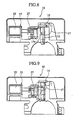
- the electrical steering lock device 10 of the first embodiment includes a steering-lock prevention device 25.
- the steering-lock prevention device is described with reference to FIG. 4 and FIGS. 8 to 10.
- FIG. 4 is a front view illustrating the electric steering lock device of the first embodiment
- FIGS. 8 to 10 are cross sectional views taken on line SA-SA.
- the steering-lock prevention device 25 serves to prevent the steering shaft 11 from a danger of unintentional lock during traveling of a vehicle and operates to preclude the lock shaft 15, urged by the spring 23, from moving in a protruding direction to lock the steering shaft 11 in an event that the drive motor 21 erroneously operates to suddenly rotate the plate cam 17 or in an event that the lock shaft 15 is suddenly dropped out from the plate cam 17 due to strenuous vibrations.
- the steering-lock prevention device 25 operates such that under a condition where the solenoid 29 remains in an ON-state, the lock plate 27 protrudes into an engaging concave portion 15a and is located therein as shown in FIG. 9 to restrict protruding and retracting movements of the lock shaft 15.
- the solenoid 29 remains in an OFF-state, as shown in FIG. 8, the lock plate 27 is returned to a retracted position by the action of a return spring, not shown, disposed in the solenoid 29, permitting the lock shaft 15 to operate for protruding and retracting movements.
- Vehicle Parking Condition Under Steering-Lock Condition
- the lock shaft 15 of the electrical steering lock device 10 assumes the protruding position under which rotation of the steering lock shaft 11 is blocked. This allows the vehicle to be burglar-proofed.
- the solenoid 29 of the steering-lock prevention device 25 is turned on as shown in FIG 9 to cause the lock plate 27 to enter the engaging concave portion 15a of the lock shaft 15, thereby preventing a danger of the steering shaft 11 being suddenly locked.
- the vehicle Under the unlocked condition of the steering shaft 11, the vehicle enters a condition available to drive the vehicle, enabling start-up of the engine.
- the lock shaft 15 is maintained in the retracting position. This prevents the steering shaft 11 from being unintentionally locked during traveling of the vehicle.
- the protruding and retracting speeds at which the lock shaft 15 moves are determined such that during unlocking process (in the sequence shown in FIG. 5 ⁇ FIG. 6 ⁇ FIG. 7) wherein the steering shaft 11 is switched from the locked condition to the unlocked condition, the first speed V1 associated with the inside of the lock groove 13 is lower than the second speed V2 associated with the outside of the lock groove 13, the lock shaft 15 is enabled to escape from the inside of the lock groove 13 to the outside of the lock groove 13 with increased torque.
- the lock shaft 15 is enabled to reliably disengage from the lock groove 13 without causing the drive motor 21 from being largely sized. Also, when this takes place, since the second speed V2 is set to be higher than the first speed V1, no delay occurs in unlocking time.
- FIGS. 12 to 14 show an electrical steering lock device of a second embodiment of the present invention. Also, the same component parts as those of the first embodiments bear like reference numerals and description of a structure and operation as well as effects is omitted.
- the steering lock device 30 of the second embodiment mainly differs from the first embodiment in two points described below.
- the plate cam 31 is set to have a contoured profile by which the lock shaft 15 is caused to move in a full stroke at a rotational angle of 270° and differs from the first embodiment in that the area S2 corresponding to the second speed V2 is set to have a rotational angle in a range between 90° and 270°.
- the electrical steering lock device 30 differs from the first embodiment in that as shown in FIGS. 12 and 13, the plate cam 31 and the cam follower 15 is determined so as to include the area S1, associated with the first speed V2, which is wider than the area S2 associated with the second speed V1. More particularly, forming the plate cam 31 to be different in contoured shape by overlapping a first plate segment 31a and a second plate segment 31b allows the sliding surface 32 of the plate cam 31 to be formed such that the area S1 associated with the first speed V1 is wider than the area S2 associated with the second speed V2.
- the electrical steering lock device 30 of the second embodiment takes the form of a cam structure that is suited to be used for high load condition through the use of the area S1 (an area in which the lock shaft 15 remains in the lock groove 13) associated with the first speed V1.
- the sliding surface 32 can be set to be narrow in the area S2 associated with the second speed V2, it is advantageous for the plate cam 31 to be formed in a compact structure.
- the protruding and retracting speeds at which the lock shaft moves are set in a way to allow the first speed, associated with the inside of the lock groove, to be lower than the second speed associated with the outside of the lock groove, enabling the lock shaft to disengage from the lock groove to the outside thereof with increased torque.
- This enables the lock shaft to reliably disengage from the lock groove without causing the drive unit to be largely sized. Also, with the present invention, it does not matter if the first speed and the second speed are necessarily fixed.
- a retracting force of the lock shaft to be applied by the drive unit is set using the cam mechanism
- the present invention may be altered such that the retracting force of the lock shaft is set using output control of the drive unit per se.
- the invention defined in Claim 1 can be realized in a simplified structure without causing the drive unit to be largely sized.
- the present invention since the sliding surface between the drive member and the cam follower includes an area associated with the first speed that is set to be wider than another area associated with the second speed, the present invention has advantageous effects as mentioned above and, in addition, makes it possible to provide a cam structure suited for a high load condition occurring in the area (at a region in which the lock shaft remains in the lock groove) associated with the first speed.
- the present invention makes it possible to set the sliding surface to be narrow in the area associated with the second speed while rendering the structure to be suited for high load, an advantage results in the formation of the drive member formed in a compact structure.
Abstract
Description
- The present invention relates to an electrical steering lock device for anti-theft of a vehicle and a related method.
- An electrical steering lock device, disclosed in Japanese Patent Provisional Publication No. 2002-205622, is arranged to render a lock shaft, adapted to protrude and retract in linkage with an electric motor, engageable with and disengageable from a steering shaft to lock and unlock rotation of the steering shaft.
- FIGS. 1 and 2 show how a
steering shaft 101 is unlocked from a locked condition to an unlocked condition in an electricalsteering lock device 100 of the type mentioned above. Under such a locked condition of thesteering shaft 101 as shown in FIG. 1, a wall surface of alock groove 103 is held in strongly pressured contact with thelock shaft 102 due to a restoring force X applied to thesteering shaft 101 resulting from frictional resistance between tires and road surface. For this reason, during a process in which thesteering shaft 101 is unlocked, thelock shaft 102 is applied with increased load when thelock shaft 102 is moved from the lock groove 103 (in a way as shown in FIG 1→ FIG. 2), whereas no load is applied to thelock shaft 102 after thelock shaft 102 has disengaged from the lock groove 103 (in a way as shown in FIG 2→ FIG 3). - As a result, the
lock shaft 102, which protrudes and retracts upon receipt of a fixed drive force from the electric motor, undergoes an issue with an inability of disengaging from thelock groove 103 depending upon a magnitude of load being applied. - The present invention has been completed with the above issue in mind and has an object to provide an electrical steering lock device, that is able to reliably disengage a lock shaft from a lock groove, and a related method.
- In one aspect of the present invention, an electrical steering lock device comprises a lock shaft operative to protrude into and retract from a lock groove, formed on a steering shaft, such that the lock shaft assumes a protruding position to engage with the lock groove for locking rotation of the steering shaft while assuming a retracting position to disengage from the lock groove for unlocking rotation of the steering shaft, and a drive unit for protruding and retracting the lock shaft, wherein a retracting force, with which the lock shaft is retracted from the lock groove by the drive unit, is set such that the retracting force, occurring when the lock shaft is moved inside the lock groove, is set to be greater than that occurring when the lock shaft is moved outside the lock groove.
- In another aspect of the present invention, there is provided a method of locking a steering shaft, comprising preparing a lock groove formed on a steering shaft, preparing a steering shaft formed with a lock groove, preparing a lock shaft operative to protrude into and retract from the lock groove such that the lock shaft assumes a protruding position to engage with the lock groove for blocking rotation of the steering shaft while assuming a retracting position to disengage from the lock groove for unlocking rotation of the steering shaft, and driving the lock shaft in protruding and retracting directions with a retracting force, occurring when the lock shaft is retracted from the lock groove by the drive unit, which varies such that the retracting force, occurring when the lock shaft is moved inside the lock groove, is greater than that occurring when the lock shaft is moved outside the lock groove.
-
- FIG. 1 is a view illustrating a locked condition of a steering shaft in an electrical steering lock device of a state-of-the art.
- FIG. 2 is a view illustrating a status in a mid-course wherein the steering shaft is progressively unlocked in the electrical steering lock device shown in FIG. 1.
- FIG. 3 is a view illustrating an unlocked condition of the steering shaft in the electrical steering lock device shown in FIG. 1.
- FIG. 4 is a front view illustrating an electrical steering lock device of a first embodiment of the present invention.
- FIG. 5 is a schematic cross sectional view showing an essential part of the electrical steering lock device shown in FIG. 4, with a steering shaft being shown in a locked condition.
- FIG. 6 is a schematic cross sectional view showing the essential part of the electrical steering lock device shown in FIG 4, with the steering shaft being shown in a midway to be moved in an unlocked condition.
- FIG. 7 is a schematic cross sectional view showing the essential part of the electrical steering lock device shown in FIG. 4, with the steering shaft being shown in the unlocked condition.
- FIG. 8 is a cross sectional view taken on line SA-SA in FIG. 4 and showing the steering shaft remaining in the locked condition like in FIG. 2.
- FIG. 9 is a cross sectional view taken on line SA-SA in FIG. 4 and showing the steering shaft remaining in the locked condition of like in FIG. 4.
- FIG. 10 is a cross sectional view taken on line SA-SA in FIG. 4 and showing a condition where a drive motor encounters erroneous operation.
- FIG. 11 is a cam displacement diagram showing the relationship between a rotational angle of a cam and a cam follower (lock shaft).
- FIG. 12 is a front view illustrating an electrical steering lock device of a second embodiment of the present invention.
- FIG. 13 is an enlarged view of a plate cam of the electrical steering lock device shown in FIG. 12.
- FIG. 14 is a cam displacement diagram showing the relationship between a rotational angle of a cam and a cam follower (lock shaft) in the electrical steering lock device of the second embodiment.
-
- Now, embodiments of the present invention are described below with reference to the accompanying drawings.
- An electrical steering lock device of a first embodiment of the present invention is described below in connection with FIGS. 4 to 11. FIGS. 5 to 7 are schematic cross sectional views illustrating essential parts of the electrical steering lock device of the first embodiment.
- As shown in FIGS. 5 to 7, the
steering lock device 10 has a fundamental structure that is comprised of alock shaft 15, serving as a "cam follower", which is operative to protrude into or retract from alock groove 13 formed on asteering shaft 11, aplate cam 17 serving as a "drive member" for operating thelock shaft 15 for protruding and retracting movements, and a drive motor (designated atreference numeral 21 in FIG. 4), serving as a drive device which is not shown, that is connected to theplate cam 17 through a gear reduction mechanism (designated atreference numeral 19 in FIG. 4), which is not shown. - The
lock shaft 15 is operative to assume a protruding position, as shown in FIG. 5, in which thelock shaft 15 is placed inside thelock groove 13 for blocking rotation of thesteering shaft 11 and a retracting position, as shown in FIG. 7, in which thelock shaft 15 is dislocated outside thelock groove 13 for thereby unlocking rotation of thesteering shaft 11. - Formed on the
lock shaft 15, serving as the cam follower, is a head portion that is formed with a plate-like contact element 16. Held in abutting engagement with thecontact element 16 of thelock shaft 15 at a retracting side (shown at an upper area of FIGS. 5 to 7) is a compression spring (designated byreference numeral 23 in FIG. 4), and held in abutting engagement with thecontact element 16 at a protruding side (shown at a lower area in FIGS. 5 to 7) is theplate cam 17 that serves as the drive member. This allows thelock shaft 15 to be applied with urging force F at all times from the retracting side toward the protruding side, while thelock shaft 15 is made operative to move in protruding or retracting directions accompanied by rotation of theplate cam 17 that is placed opposite to the compression spring. - The subject matter of the first embodiment is characterized by the
plate cam 17 with a contoured profile that is determined such that thelock shaft 15 protrudes and retracts at differing speeds; that is, a first speed V1, occurring when thelock shaft 15 moves inside thelock groove 13, and a second speed V2 at which thelock shaft 15 moves in an area outside thelock groove 13, with the first speed being set to be slower than the second speed. That is, a vorticosely-contoured profile of the plate-like cam 17 formed about a center of arotary shaft 18 is so determined as to allow an area S1 [with a rotational angle in a range from 0° (at a stroke of 0) to 90° (at a stroke of a)], corresponding to the first speed V1, to be set in a decreased divergence angle while an area S2 [with a rotational angle in a range from 90° (at the stroke of a) to 180° (at a full stroke)] corresponding to the second speed V2 has an increased divergence angle. Also, the present invention has no object on a contoured profile in an area S3 beyond the full stroke. - With the electrical
steering lock device 10 of the first embodiment with such a structure, since a traveling speed (first speed V1) at which thelock shaft 15 travels in thelock groove 13 is set to be slow, thelock shaft 15 can be escaped from thelock groove 13 toward the outside thereof with increased torque. This results in a capability of thelock shaft 15 being disengaged from thelock groove 13 without causing theelectric motor 21 to be largely sized. When this takes place, the second speed V2 is determined to be higher than the first speed V1, resulting in no probability of the occurrence in delay in an unlocking time. - Also, the electrical
steering lock device 10 of the first embodiment includes a steering-lock prevention device 25. Hereunder, the steering-lock prevention device is described with reference to FIG. 4 and FIGS. 8 to 10. FIG. 4 is a front view illustrating the electric steering lock device of the first embodiment, and FIGS. 8 to 10 are cross sectional views taken on line SA-SA. - The steering-
lock prevention device 25 serves to prevent thesteering shaft 11 from a danger of unintentional lock during traveling of a vehicle and operates to preclude thelock shaft 15, urged by thespring 23, from moving in a protruding direction to lock thesteering shaft 11 in an event that thedrive motor 21 erroneously operates to suddenly rotate theplate cam 17 or in an event that thelock shaft 15 is suddenly dropped out from theplate cam 17 due to strenuous vibrations. - The steering-
lock prevention device 25 operates such that under a condition where thesolenoid 29 remains in an ON-state, thelock plate 27 protrudes into an engagingconcave portion 15a and is located therein as shown in FIG. 9 to restrict protruding and retracting movements of thelock shaft 15. As a result, even if the motor is erroneously operated, as shown in FIG. 10, no danger is caused for the steering shaft to be locked during traveling of the vehicle. On the contrary, if thesolenoid 29 remains in an OFF-state, as shown in FIG. 8, thelock plate 27 is returned to a retracted position by the action of a return spring, not shown, disposed in thesolenoid 29, permitting thelock shaft 15 to operate for protruding and retracting movements. - A sequence of operation of the electrical steering lock device with such a structure is described.
- Initially during parking of the vehicle, the
lock shaft 15 of the electricalsteering lock device 10 assumes the protruding position under which rotation of thesteering lock shaft 11 is blocked. This allows the vehicle to be burglar-proofed. - Next, before engine starts up, if a switch, not shown, located in the vicinity of a driver's seat is pressed, the
drive motor 21 of the electricalsteering lock device 10 is actuated to shift thelock shaft 15 from the protruding position toward the retracting position in a sequence shown in FIG. 5→FIG. 6→FIG. 7. This allows thesteering lock shaft 11 to be unlocked. - As the
lock shaft 15 is moved to the retracting position, thesolenoid 29 of the steering-lock prevention device 25 is turned on as shown in FIG 9 to cause thelock plate 27 to enter the engagingconcave portion 15a of thelock shaft 15, thereby preventing a danger of thesteering shaft 11 being suddenly locked. Under the unlocked condition of thesteering shaft 11, the vehicle enters a condition available to drive the vehicle, enabling start-up of the engine. - During traveling of the vehicle, due to the operation of the steering-
lock prevention device 25 of the steering lock device set forth above, thelock shaft 15 is maintained in the retracting position. This prevents thesteering shaft 11 from being unintentionally locked during traveling of the vehicle. - As the engine is stopped to enter ACC, under a condition where the steering-lack preventive condition shown in FIG. 9, the
solenoid 29 is turned off and thelock plate 27 disengages from the engagingconcave portion 15a of thelock shaft 15. This allows the steering-lock to be enabled. - Under such a condition, if the switch, not shown, of the electrical
steering lock device 10 is pressed again, thedrive motor 21 is operated and thelock shaft 11 enters thelock groove 13 in a sequence as shown in FIG. 7→FIG. 6→ FIG. 5. This allows the steeringshaft 11 to be locked, resulting in a condition where the vehicle is burglar-proofed. - Here, with the electrical
steering lock device 10 of the first embodiment, since the protruding and retracting speeds at which thelock shaft 15 moves are determined such that during unlocking process (in the sequence shown in FIG. 5→FIG. 6→FIG. 7) wherein the steeringshaft 11 is switched from the locked condition to the unlocked condition, the first speed V1 associated with the inside of thelock groove 13 is lower than the second speed V2 associated with the outside of thelock groove 13, thelock shaft 15 is enabled to escape from the inside of thelock groove 13 to the outside of thelock groove 13 with increased torque. - Thus, with the electrical
steering lock device 10 of the first embodiment, thelock shaft 15 is enabled to reliably disengage from thelock groove 13 without causing thedrive motor 21 from being largely sized. Also, when this takes place, since the second speed V2 is set to be higher than the first speed V1, no delay occurs in unlocking time. - FIGS. 12 to 14 show an electrical steering lock device of a second embodiment of the present invention. Also, the same component parts as those of the first embodiments bear like reference numerals and description of a structure and operation as well as effects is omitted.
- The
steering lock device 30 of the second embodiment mainly differs from the first embodiment in two points described below. - First, as shown in FIG. 14, the
plate cam 31 is set to have a contoured profile by which thelock shaft 15 is caused to move in a full stroke at a rotational angle of 270° and differs from the first embodiment in that the area S2 corresponding to the second speed V2 is set to have a rotational angle in a range between 90° and 270°. - Secondly, the electrical
steering lock device 30 differs from the first embodiment in that as shown in FIGS. 12 and 13, theplate cam 31 and thecam follower 15 is determined so as to include the area S1, associated with the first speed V2, which is wider than the area S2 associated with the second speed V1. More particularly, forming theplate cam 31 to be different in contoured shape by overlapping afirst plate segment 31a and asecond plate segment 31b allows the slidingsurface 32 of theplate cam 31 to be formed such that the area S1 associated with the first speed V1 is wider than the area S2 associated with the second speed V2. - Thus, since the sliding
surface 32 of theplate cam 31 is determined such that the area S1 associated with the first speed V1 is wider than the area S2 associated with the second speed V2, the electricalsteering lock device 30 of the second embodiment takes the form of a cam structure that is suited to be used for high load condition through the use of the area S1 (an area in which thelock shaft 15 remains in the lock groove 13) associated with the first speed V1. In other words, the slidingsurface 32 can be set to be narrow in the area S2 associated with the second speed V2, it is advantageous for theplate cam 31 to be formed in a compact structure. - According to the present invention, the protruding and retracting speeds at which the lock shaft moves are set in a way to allow the first speed, associated with the inside of the lock groove, to be lower than the second speed associated with the outside of the lock groove, enabling the lock shaft to disengage from the lock groove to the outside thereof with increased torque. This enables the lock shaft to reliably disengage from the lock groove without causing the drive unit to be largely sized. Also, with the present invention, it does not matter if the first speed and the second speed are necessarily fixed.
- Also, while with the first and second embodiments set forth above, a retracting force of the lock shaft to be applied by the drive unit is set using the cam mechanism, the present invention may be altered such that the retracting force of the lock shaft is set using output control of the drive unit per se.
- As set forth above, according to the present invention, pulling the lock shaft out from the inside of the lock groove to the outside thereof with increased torque enables the lock shaft to reliably disenagge from the lock groove.
- Further, according to the present invention, due to the presence of the cam mechanism, comprised of the cam follower and the drive member, by which the first speed associated with the inside of the lock groove is lower than the second speed associated with the outside of the lock groove, the invention defined in
Claim 1 can be realized in a simplified structure without causing the drive unit to be largely sized. - Besides, since the sliding surface between the drive member and the cam follower includes an area associated with the first speed that is set to be wider than another area associated with the second speed, the present invention has advantageous effects as mentioned above and, in addition, makes it possible to provide a cam structure suited for a high load condition occurring in the area (at a region in which the lock shaft remains in the lock groove) associated with the first speed. In other words, since the present invention makes it possible to set the sliding surface to be narrow in the area associated with the second speed while rendering the structure to be suited for high load, an advantage results in the formation of the drive member formed in a compact structure.
- The entire contents of Japanese Patent Application No. P2003-169794 with a filing date of June 13, 2003 is herein incorporated by reference.
- Although the present invention has been described above by reference to certain embodiments of the invention, the invention is not limited to the embodiments described above and modifications will occur to those skilled in the art, in light of the teachings. The scope of the invention is defined with reference to the following claims.
Claims (11)
- An electrical steering lock device comprising:a lock shaft operative to protrude into and retract from a lock groove, formed on a steering shaft, such that the lock shaft assumes a protruding position to engage with the lock groove for blocking rotation of the steering shaft while assuming a retracting position to disengage from the lock groove for unlocking rotation of the steering shaft; anda drive unit for protruding and retracting the lock shaft, whereina retracting force, with which the lock shaft is retracted from the lock groove by the drive unit, is set such that the retracting force, occurring when the lock shaft is moved inside the lock groove, is set to be greater than that occurring when the lock shaft is moved outside the lock groove.
- The electrical steering lock device according to claim 1, further comprising:a drive member linked with the drive unit in engagement with the lock shaft, which serves as a cam follower, to protrude and retract the lock shaft with respect to the lock groove, whereinthe cam follower and the drive member form a cam mechanism in which a first speed, at which the lock shaft moves inside the lock groove, is set to be lower than a second speed at which the lock shaft moves outside the lock groove whereby the retracting force, occurring when the lock shaft is retracted from the lock groove by the drive unit, is set such that the retracting force, occurring when the lock shaft is moved inside the lock groove, is set to be greater than that occurring when the lock shaft is moved outside the lock groove.
- The electrical steering lock device according to claim 2, wherein
a sliding surface between the drive member and the cam follower includes an area associated with the first speed which is set to be wider than another area associated with the second speed. - The electrical steering lock device according to claim 2, wherein
the drive member includes a cam that has a cam lobe with a contoured cam surface whereby the lock shaft is operative to engage with or disengage from the lock groove with increased torque at the first speed. - The electrical steering lock device according to claim 2, wherein
the drive member includes a cam that has a cam lobe with a contoured cam surface to allow the lock shaft to move at the first speed, when the lock shaft moves inside the lock groove, to be lower than the second speed at which the lock shaft moves outside the lock groove. - The electrical steering lock device according to claim 1, further comprising:a steering-lock prevention device cooperating with the lock shaft and operative to restrict unintentional movement of the lock shaft toward the protruding position..
- The electrical steering lock device according to claim 6, wherein
the lock shaft includes an engaging portion; and
the steering-lock prevention device includes a lock member selectively engageable with the engaging portion of the lock shaft to block unintentional locking movement of the lock shaft. - The electrical steering lock device according to claim 2, wherein
the drive member includes a cam that has a sliding surface composed of a first area, in which the lock shaft moves at the first speed, that is wider than a second area in which the lock shaft moves at the second speed. - The electrical steering lock device according to claim 8, wherein
the cam includes a first cam plate, formed with the first area, and a second cam plate, formed with the second area, by which the sliding surface is provided. - An electrical steering lock device comprising:lock means operative to protrude into and retract from a lock groove, formed on a steering shaft, such that the lock means assumes a protruding position to engage with the lock groove for locking rotation of the steering shaft while assuming a retracting position to disengage from the lock groove for unlocking rotation of the steering shaft; anddrive means for protruding and retracting the lock means, whereina retracting force, occurring when the lock means is retracted from the lock groove by the drive means, is set such that the retracting force, occurring when the lock means is moved inside the lock groove, is greater than that occurring when the lock means is moved outside the lock groove.
- A method of locking a steering shaft, comprising:preparing a steering shaft formed with a lock groove;preparing a lock shaft operative to protrude into and retract from the lock groove such that the lock shaft assumes a protruding position to engage with the lock groove for blocking rotation of the steering shaft while assuming a retracting position to disengage from the lock groove for unlocking rotation of the steering shaft; anddriving the lock shaft in protruding and retracting directions with a retracting force, occurring when the lock shaft is retracted from the lock groove by the drive unit, which varies such that the retracting force, occurring when the lock shaft is moved inside the lock groove, is greater than that occurring when the lock shaft is moved outside the lock groove.
Applications Claiming Priority (2)
| Application Number | Priority Date | Filing Date | Title |
|---|---|---|---|
| JP2003169794 | 2003-06-13 | ||
| JP2003169794A JP4248948B2 (en) | 2003-06-13 | 2003-06-13 | Electric steering lock device |
Publications (3)
| Publication Number | Publication Date |
|---|---|
| EP1486386A2 true EP1486386A2 (en) | 2004-12-15 |
| EP1486386A3 EP1486386A3 (en) | 2005-03-23 |
| EP1486386B1 EP1486386B1 (en) | 2009-04-15 |
Family
ID=33296912
Family Applications (1)
| Application Number | Title | Priority Date | Filing Date |
|---|---|---|---|
| EP20040013676 Expired - Fee Related EP1486386B1 (en) | 2003-06-13 | 2004-06-09 | Electrical steering lock device for an automotive vehicle and related method |
Country Status (5)
| Country | Link |
|---|---|
| US (1) | US7024895B2 (en) |
| EP (1) | EP1486386B1 (en) |
| JP (1) | JP4248948B2 (en) |
| CN (1) | CN1288012C (en) |
| DE (1) | DE602004020543D1 (en) |
Cited By (3)
| Publication number | Priority date | Publication date | Assignee | Title |
|---|---|---|---|---|
| EP1600343A1 (en) * | 2004-05-24 | 2005-11-30 | Alpha Corporation | Electric steering lock apparatus |
| WO2006048423A1 (en) * | 2004-11-05 | 2006-05-11 | Valeo Sicherheitssysteme Gmbh | Steering lock |
| EP1727714A2 (en) * | 2004-02-21 | 2006-12-06 | Strattec Security Corporation | Steering column lock apparatus and method |
Families Citing this family (17)
| Publication number | Priority date | Publication date | Assignee | Title |
|---|---|---|---|---|
| US7325140B2 (en) * | 2003-06-13 | 2008-01-29 | Engedi Technologies, Inc. | Secure management access control for computers, embedded and card embodiment |
| JP4038132B2 (en) * | 2003-01-31 | 2008-01-23 | 株式会社東海理化電機製作所 | Electric steering lock device |
| US20050120761A1 (en) * | 2003-12-03 | 2005-06-09 | Rouleau James E. | Column assembly of a vehicle having a steering column to be locked and unlocked |
| JP2005297645A (en) * | 2004-04-07 | 2005-10-27 | Tokai Rika Co Ltd | Steering lock device |
| JP4348245B2 (en) * | 2004-07-08 | 2009-10-21 | 株式会社東海理化電機製作所 | Steering lock device |
| JP3808889B2 (en) * | 2004-10-12 | 2006-08-16 | 株式会社アルファ | Electric lock device |
| JP2006273115A (en) * | 2005-03-29 | 2006-10-12 | Alpha Corp | Electric steering lock device and method of controlling the electric steering lock device |
| JP4587864B2 (en) * | 2005-04-11 | 2010-11-24 | 株式会社アルファ | Electric steering lock device |
| KR101224280B1 (en) | 2005-10-19 | 2013-01-18 | 가부시키가이샤 유신 | Motor-driven steering lock device |
| JP2007269176A (en) * | 2006-03-31 | 2007-10-18 | Alpha Corp | Steering lock device |
| DE112007001032T5 (en) * | 2006-04-27 | 2009-05-20 | Stoneridge Control Devices, Inc., Canton | Actuator for steering shaft lock |
| JP4856556B2 (en) * | 2007-01-15 | 2012-01-18 | 株式会社東海理化電機製作所 | Electric steering lock device |
| JP5020153B2 (en) * | 2008-04-18 | 2012-09-05 | 株式会社ユーシン | Electric steering lock device |
| DE102012104510A1 (en) * | 2012-05-24 | 2013-11-28 | Dorma Gmbh + Co. Kg | Lock for a door |
| WO2015049951A1 (en) * | 2013-10-04 | 2015-04-09 | 株式会社 アルファ | Electric steering lock |
| CN103926081B (en) * | 2014-04-28 | 2016-11-16 | 中国航天空气动力技术研究院 | A kind of plug-in adaptive locking device being applied to punching engine test bay |
| CN114502811B (en) * | 2019-10-09 | 2023-11-28 | 索斯科公司 | Electronically actuated and locked glove box system |
Citations (4)
| Publication number | Priority date | Publication date | Assignee | Title |
|---|---|---|---|---|
| US3553987A (en) * | 1968-08-21 | 1971-01-12 | Chrysler Corp | Steering column and transmission control lock |
| US20020069683A1 (en) * | 2000-08-10 | 2002-06-13 | Kiekert Ag | Steering wheel lock |
| US20020088257A1 (en) * | 2001-01-09 | 2002-07-11 | Dimig Steven J. | Steering column lock apparatus and method |
| US20030067216A1 (en) * | 2001-10-04 | 2003-04-10 | Toshihiro Nagae | Electronic automobile anti-theft apparatus |
Family Cites Families (1)
| Publication number | Priority date | Publication date | Assignee | Title |
|---|---|---|---|---|
| JP3749126B2 (en) | 2001-01-11 | 2006-02-22 | 株式会社ユーシン | Electric steering lock device |
-
2003
- 2003-06-13 JP JP2003169794A patent/JP4248948B2/en not_active Expired - Lifetime
-
2004
- 2004-06-09 DE DE200460020543 patent/DE602004020543D1/en active Active
- 2004-06-09 EP EP20040013676 patent/EP1486386B1/en not_active Expired - Fee Related
- 2004-06-10 US US10/864,598 patent/US7024895B2/en active Active
- 2004-06-14 CN CNB200410048259XA patent/CN1288012C/en not_active Expired - Fee Related
Patent Citations (4)
| Publication number | Priority date | Publication date | Assignee | Title |
|---|---|---|---|---|
| US3553987A (en) * | 1968-08-21 | 1971-01-12 | Chrysler Corp | Steering column and transmission control lock |
| US20020069683A1 (en) * | 2000-08-10 | 2002-06-13 | Kiekert Ag | Steering wheel lock |
| US20020088257A1 (en) * | 2001-01-09 | 2002-07-11 | Dimig Steven J. | Steering column lock apparatus and method |
| US20030067216A1 (en) * | 2001-10-04 | 2003-04-10 | Toshihiro Nagae | Electronic automobile anti-theft apparatus |
Cited By (5)
| Publication number | Priority date | Publication date | Assignee | Title |
|---|---|---|---|---|
| EP1727714A2 (en) * | 2004-02-21 | 2006-12-06 | Strattec Security Corporation | Steering column lock apparatus and method |
| EP1727714A4 (en) * | 2004-02-21 | 2009-11-04 | Strattec Security Corp | Steering column lock apparatus and method |
| EP1600343A1 (en) * | 2004-05-24 | 2005-11-30 | Alpha Corporation | Electric steering lock apparatus |
| WO2006048423A1 (en) * | 2004-11-05 | 2006-05-11 | Valeo Sicherheitssysteme Gmbh | Steering lock |
| US7856858B2 (en) | 2004-11-05 | 2010-12-28 | Valeo Sicherheitssysteme Gmbh | Safe gear box for electrical steering column lock |
Also Published As
| Publication number | Publication date |
|---|---|
| EP1486386A3 (en) | 2005-03-23 |
| US20040250577A1 (en) | 2004-12-16 |
| DE602004020543D1 (en) | 2009-05-28 |
| US7024895B2 (en) | 2006-04-11 |
| CN1288012C (en) | 2006-12-06 |
| JP4248948B2 (en) | 2009-04-02 |
| CN1572606A (en) | 2005-02-02 |
| JP2005001606A (en) | 2005-01-06 |
| EP1486386B1 (en) | 2009-04-15 |
Similar Documents
| Publication | Publication Date | Title |
|---|---|---|
| US7024895B2 (en) | Electrical steering lock device and related method | |
| US5906120A (en) | Automotive vehicle steering column lock mechanism | |
| US7021093B2 (en) | Antitheft device for vehicle | |
| JP2713971B2 (en) | Operating device for automatic transmission | |
| KR100686997B1 (en) | Electric steering lock apparatus | |
| US5950782A (en) | Arrangement and method for locking a selector mechanism of an automatically operating change-speed gearbox | |
| EP0655570B1 (en) | Shift lever apparatus | |
| US4967883A (en) | Automatic transmission shift lever device with park and ignition interlock | |
| CN110573688B (en) | Lock for a motor vehicle | |
| JP3819925B2 (en) | Electric steering lock device | |
| JP3962968B2 (en) | Parking device for automobile transmission | |
| JPH0667160U (en) | Rotating seat for vehicle | |
| JP4680056B2 (en) | Electric steering lock system | |
| JP2653664B2 (en) | Steering lock control device | |
| JP3289034B2 (en) | Movable step drive for vehicles | |
| US5846158A (en) | Shift-locking apparatus for column at shift lever | |
| JP2573885Y2 (en) | Steering lock device | |
| US7559874B2 (en) | Vehicle shift module | |
| JP3082806U (en) | Neutral range false start prevention device for AT vehicles | |
| JPH03204361A (en) | Steering lock device | |
| KR100460894B1 (en) | Auto transmission lever key inter lock system | |
| JP2571723B2 (en) | Steering lock device | |
| JP2846315B2 (en) | Shift lever control device for automatic transmission | |
| CN111425080A (en) | Door lock for motor vehicle | |
| JPH01106754A (en) | Lock device for shift lever |
Legal Events
| Date | Code | Title | Description |
|---|---|---|---|
| PUAI | Public reference made under article 153(3) epc to a published international application that has entered the european phase |
Free format text: ORIGINAL CODE: 0009012 |
|
| 17P | Request for examination filed |
Effective date: 20040609 |
|
| AK | Designated contracting states |
Kind code of ref document: A2 Designated state(s): AT BE BG CH CY CZ DE DK EE ES FI FR GB GR HU IE IT LI LU MC NL PL PT RO SE SI SK TR |
|
| AX | Request for extension of the european patent |
Extension state: AL HR LT LV MK |
|
| PUAL | Search report despatched |
Free format text: ORIGINAL CODE: 0009013 |
|
| AK | Designated contracting states |
Kind code of ref document: A3 Designated state(s): AT BE BG CH CY CZ DE DK EE ES FI FR GB GR HU IE IT LI LU MC NL PL PT RO SE SI SK TR |
|
| AX | Request for extension of the european patent |
Extension state: AL HR LT LV MK |
|
| RIC1 | Information provided on ipc code assigned before grant |
Ipc: 7B 60R 25/00 A Ipc: 7B 60R 25/02 B |
|
| AKX | Designation fees paid |
Designated state(s): DE GB |
|
| GRAP | Despatch of communication of intention to grant a patent |
Free format text: ORIGINAL CODE: EPIDOSNIGR1 |
|
| GRAS | Grant fee paid |
Free format text: ORIGINAL CODE: EPIDOSNIGR3 |
|
| GRAA | (expected) grant |
Free format text: ORIGINAL CODE: 0009210 |
|
| AK | Designated contracting states |
Kind code of ref document: B1 Designated state(s): DE GB |
|
| REG | Reference to a national code |
Ref country code: GB Ref legal event code: FG4D |
|
| REF | Corresponds to: |
Ref document number: 602004020543 Country of ref document: DE Date of ref document: 20090528 Kind code of ref document: P |
|
| PLBE | No opposition filed within time limit |
Free format text: ORIGINAL CODE: 0009261 |
|
| STAA | Information on the status of an ep patent application or granted ep patent |
Free format text: STATUS: NO OPPOSITION FILED WITHIN TIME LIMIT |
|
| 26N | No opposition filed |
Effective date: 20100118 |
|
| PGFP | Annual fee paid to national office [announced via postgrant information from national office to epo] |
Ref country code: DE Payment date: 20190627 Year of fee payment: 16 Ref country code: GB Payment date: 20190627 Year of fee payment: 16 |
|
| REG | Reference to a national code |
Ref country code: DE Ref legal event code: R119 Ref document number: 602004020543 Country of ref document: DE |
|
| GBPC | Gb: european patent ceased through non-payment of renewal fee |
Effective date: 20200609 |
|
| PG25 | Lapsed in a contracting state [announced via postgrant information from national office to epo] |
Ref country code: GB Free format text: LAPSE BECAUSE OF NON-PAYMENT OF DUE FEES Effective date: 20200609 |
|
| PG25 | Lapsed in a contracting state [announced via postgrant information from national office to epo] |
Ref country code: DE Free format text: LAPSE BECAUSE OF NON-PAYMENT OF DUE FEES Effective date: 20210101 |