EP1487100A1 - Multi-channel power amplifier with channels independently self-configuring bridge or single-ended output, particulary for audio applications - Google Patents
Multi-channel power amplifier with channels independently self-configuring bridge or single-ended output, particulary for audio applications Download PDFInfo
- Publication number
- EP1487100A1 EP1487100A1 EP03425358A EP03425358A EP1487100A1 EP 1487100 A1 EP1487100 A1 EP 1487100A1 EP 03425358 A EP03425358 A EP 03425358A EP 03425358 A EP03425358 A EP 03425358A EP 1487100 A1 EP1487100 A1 EP 1487100A1
- Authority
- EP
- European Patent Office
- Prior art keywords
- channel
- amplifier
- channels
- power amplifier
- ended
- Prior art date
- Legal status (The legal status is an assumption and is not a legal conclusion. Google has not performed a legal analysis and makes no representation as to the accuracy of the status listed.)
- Withdrawn
Links
Images


Classifications
-
- H—ELECTRICITY
- H03—ELECTRONIC CIRCUITRY
- H03F—AMPLIFIERS
- H03F3/00—Amplifiers with only discharge tubes or only semiconductor devices as amplifying elements
- H03F3/72—Gated amplifiers, i.e. amplifiers which are rendered operative or inoperative by means of a control signal
-
- H—ELECTRICITY
- H03—ELECTRONIC CIRCUITRY
- H03F—AMPLIFIERS
- H03F1/00—Details of amplifiers with only discharge tubes, only semiconductor devices or only unspecified devices as amplifying elements
- H03F1/02—Modifications of amplifiers to raise the efficiency, e.g. gliding Class A stages, use of an auxiliary oscillation
- H03F1/0205—Modifications of amplifiers to raise the efficiency, e.g. gliding Class A stages, use of an auxiliary oscillation in transistor amplifiers
- H03F1/0277—Selecting one or more amplifiers from a plurality of amplifiers
-
- H—ELECTRICITY
- H03—ELECTRONIC CIRCUITRY
- H03F—AMPLIFIERS
- H03F1/00—Details of amplifiers with only discharge tubes, only semiconductor devices or only unspecified devices as amplifying elements
- H03F1/32—Modifications of amplifiers to reduce non-linear distortion
- H03F1/3211—Modifications of amplifiers to reduce non-linear distortion in differential amplifiers
-
- H—ELECTRICITY
- H03—ELECTRONIC CIRCUITRY
- H03F—AMPLIFIERS
- H03F3/00—Amplifiers with only discharge tubes or only semiconductor devices as amplifying elements
- H03F3/68—Combinations of amplifiers, e.g. multi-channel amplifiers for stereophonics
Definitions
- the present invention relates in general to amplifiers and in particular to amplifiers with a reduced power consumption specially for car audio and HI-FI audio applications.
- HI-FI audio systems and similar apparatuses that are intrinsically compact because of stringent installation requirements, as well as in portable apparatuses, power dissipation in final power stages, often quadrupled in order to drive a pair of loudspeakers (front and rear) for each stereo channel, may create heat balance problems.
- D-type switching amplifiers are highly efficient and are considered the most appropriate type for these applications.
- class AB power amplifiers are less efficient than switching amplifiers and a common technique for reducing power consumption of class AB amplifiers consists in configuring them in single-ended instead of in bridge configuration, whenever it is possible to do so.
- these amplifiers dissipate more power in bridge configuration than in single-ended configuration as long as the amplitude of the output signal remains smaller than the positive supply voltage.
- the patent US 5,194,821 discloses a bridge amplifier using a positive and a negative supply voltage sources, that may function in single-ended or in differential or bridge output configuration, depending on the level of the output signal. Substantially, a comparator changes the output circuital configuration of the amplifier from a bridge configuration to a single-ended configuration or vice versa by closing or opening configuring switches, when the output signal becomes smaller than or greater than a certain threshold voltage.
- Each operational amplifier OP1+, OP1-, OP2+, OP2- are respectively input with the signals Ch1 and Ch2 for driving two loudspeakers.
- a window comparator is input with the two signals Ch1 and Ch2 and positions the switches that connect the loudspeaker of the channel Ch2 either to the output of the operational amplifier (OP2+) or to a certain reference voltage V REF .
- the operational amplifier OP1- is configured by the window comparator that positions the path-selector shown within the dotted perimeter for functioning as a voltage buffer outputting the reference voltage V REF , by coupling an input thereof to a fixed voltage V F .
- each channel has a dedicated window comparator monitoring the level of the input signal of the channel that generates a logic signal for positioning the switches that configure the output power structure of the channel in single-ended or bridge configuration.
- a dedicated window comparator monitoring the level of the input signal of the channel that generates a logic signal for positioning the switches that configure the output power structure of the channel in single-ended or bridge configuration.
- a distinct voltage reference buffer is employed, to which any single-ended channel of the multi-channel amplifier of this invention is connected.
- object of the invention is a multi-channel power amplifier for driving a plurality of loads, each associated to a respective channel, each channel comprising a pair of operational amplifiers, first and second, one operational amplifier of each channel being connectable by configuring switches either in a bridge configuration with the other operational amplifier or in single-ended configuration to a constant reference voltage output by a dedicated voltage buffer of the multi-channel amplifier for driving the respective load of the channel, and further comprising a window comparator for monitoring the level of the input signal of the channel and producing a logic control signal for the configuring switches.
- a dedicated unique voltage buffer Vref_BUFFER distinct from the operational amplifiers, that outputs a reference voltage V REF
- a dedicated window comparator sensing the level of the signal input to the channel and controlling the switches that configure the output of the channel in a bridge or single-ended configuration with the voltage buffer.
- each channel essentially comprises a pair of operational amplifiers, preferably functioning in class AB for keeping as low as possible electromagnetic emissions, that may be independently connected in a configuration equivalent to a bridge power amplifier or in a configuration equivalent to a single-ended power amplifier.
- the respective load is connected between the output of an operational amplifier and the output node at the constant reference voltage V REF of the voltage buffer Vref_BUFFER.
- the second operational amplifier is inactive.
- the two operational amplifiers of a channel are connected in bridge configuration when the positions of the respective configuring switches are inverted.
- the relative each window comparator commands the second operational amplifier of the channel to tristate when the load of the channel must be driven in single-ended configuration, and resumes the second operational amplifier from tristate when the load must be driven through an output bridge.
- the novel power amplifier of this invention is particularly advantageous in applications that require more than two channels, such as in advanced car audio applications.
- the multi-channel power amplifier of this invention may have any number of channels, as shown in Figures 4, 5 and 6, that may be independently switched from a single-ended to a bridge configuration and vice versa, if not designed specifically to function always in single-ended configuration, like channel Ch5 of the amplifier of Figure 5.
- the current absorption of a single-ended channel is balanced by all other channels, and not only by the single-ended channel connected to it, as in the power amplifier of Figure 2.
- a power amplifier of this invention particularly suited for car audio applications is depicted in Figure 7. It is substantially composed of four channels ChFR, ChRR, ChRL and ChFL driving a front right, rear right, rear left and front left loudspeakers, respectively.
- audio signals are fed to the inverting (or non inverting) input of the first operational amplifiers of the pairs of the front right and rear left channels that are always connected to the respective loads, while the audio signals are fed to the non inverting (or inverting) input of the operational amplifiers of the rear right and front left channels.
- the front right and front left audio signals ChFR and ChFL are substantially two random variables whose mean values are null.
- Figures 8, 9 and 10 show results of simulations of a four channel power amplifier of this invention with a standard four bridge power amplifier, that is a four bridge power amplifier composed of standard class AB operational amplifiers, and with a high efficiency self-configuring power amplifier according to the prior art, carried out with the software program MATLABTM.
- FIG. 8 the power consumption characteristics of the compared power amplifiers in function of the power delivered to the load for certain values of phase difference.
- the power amplifiers have four channels driven with sine signals of the same amplitude and each supplying four loads of 4 ⁇ .
- the first curve refers to a four channel standard power amplifier (SPA) whichever the phase difference between the input audio signals of the channels is.
- SPA standard power amplifier
- the same curve refers also to a self-configuring four channels high efficiency power amplifier (HI_EFF) of the prior art, as depicted in Figure 2 when the front and rear channels are outphased by 180°.
- the second curve, identified with the symbol “•”, refers to the same self-configuring four channels high efficiency power amplifier (HI_EFF) of Figure 2, when the front and rear channels are outphased by 90°.
- the third curve refers to the same four channels high efficiency power amplifier (HI_EFF) of the prior art when the input audio signals of the rear and front channels are in phase.
- the same curve also refers to the self-configuring four channel power amplifier of this invention (INV) as depicted in Figure 7 whichever the phase difference between the input audio signals of the front and rear channels is.
- the current absorbed by a front (rear) channel may be compensated only by the current flowing in the rear (front) channel connected to it when it is in phase thereto, but when the currents in the front and rear channels are in phase opposition, the total current absorbed by each voltage buffer OP1- and OP3- is twice the current circulating in each channel.
- the current in the front (rear) left channel compensates the current in the front (rear) right channel, and thus even in this case the current absorbed by the voltage buffer Vref_BUFFER is practically null.
- FIG 10 are shown the performances of the power amplifier of this invention depicted in Figure 7 when the audio signals input to the (front and rear) left channels are in phase with the audio signals input to the (front and rear) right channels and when there is a phase difference of 180°.
- the front and rear channels were outphased by 3ms and each channel had a 4 ⁇ load.
Abstract
Description
- The present invention relates in general to amplifiers and in particular to amplifiers with a reduced power consumption specially for car audio and HI-FI audio applications.
- In many applications and primarily in audio reproduction systems, for example in car audios, HI-FI audio systems and similar apparatuses that are intrinsically compact because of stringent installation requirements, as well as in portable apparatuses, power dissipation in final power stages, often quadrupled in order to drive a pair of loudspeakers (front and rear) for each stereo channel, may create heat balance problems. For example, four 20 W amplifiers may have a power dissipation of about 4×12=48 W and because of the limited space available in certain apparatuses, such a relatively large power may be difficult to be dissipated without a significant increase of temperature within the apparatus.
- On the other hand, a relatively high temperature of operation may degrade the magnetic tape of cassettes or optical disks (CD), the drives of which are often tightly fitted inside a single apparatus case.
- The so-called D-type switching amplifiers are highly efficient and are considered the most appropriate type for these applications.
- Unfortunately, switching amplifiers generate electromagnetic emissions that in compact apparatuses interfere with the correct functioning of other systems, reducing their performances. For these reasons, audio signals are frequently amplified using a pair of class AB power amplifiers, operating in single-ended or in bridge configuration depending on the level of the processed signal.
- In fact, class AB power amplifiers are less efficient than switching amplifiers and a common technique for reducing power consumption of class AB amplifiers consists in configuring them in single-ended instead of in bridge configuration, whenever it is possible to do so. In fact, these amplifiers dissipate more power in bridge configuration than in single-ended configuration as long as the amplitude of the output signal remains smaller than the positive supply voltage. Unfortunately, it is not possible to use single-ended class AB amplifiers if the output surpasses this voltage because the output signal would be severely distorted by clipping.
- Techniques for automatically switching from one configuration to the other in function of the monitored level of the signal are implemented in the patents US 5,194,821, US 5,365,188 and US 5,654,688, all in the name of the same Applicant.
- The patent US 5,194,821 discloses a bridge amplifier using a positive and a negative supply voltage sources, that may function in single-ended or in differential or bridge output configuration, depending on the level of the output signal. Substantially, a comparator changes the output circuital configuration of the amplifier from a bridge configuration to a single-ended configuration or vice versa by closing or opening configuring switches, when the output signal becomes smaller than or greater than a certain threshold voltage.
- The patents US 5,365,188 and US 5,654,688 disclose a single supply dual bridge power amplifier, having a window comparator for sensing the level of input signals fed to the amplifier and driving the switches that coordinately configure the amplifier in either a bridge or in a single-ended configuration.
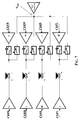
- A system of the type disclosed in the above mentioned patents is schematically shown in Figure 1.
- Four operational amplifiers OP1+, OP1-, OP2+, OP2- are respectively input with the signals Ch1 and Ch2 for driving two loudspeakers. A window comparator is input with the two signals Ch1 and Ch2 and positions the switches that connect the loudspeaker of the channel Ch2 either to the output of the operational amplifier (OP2+) or to a certain reference voltage VREF. The operational amplifier OP1-, is configured by the window comparator that positions the path-selector shown within the dotted perimeter for functioning as a voltage buffer outputting the reference voltage VREF, by coupling an input thereof to a fixed voltage VF.
- In the scheme of Figure 1, the switches of the power amplifier are shown in the position that configures the amplifier with two single-ended channels driving the respective loudspeakers.
- In car audio systems two or more pairs of amplifiers of this kind are often used for driving four loudspeakers FR (Front Right), FL (Front Left), RR (Rear Right) and RL (Rear Left) through independently equalizable channels.
- Surprisingly, it has been noticed that frequently the efficiency of this multi-channel power amplifier inexplicably drops and crosstalk effects increase.
- By investigating the possible causes of these baffling occurrences, it has been noticed that in most recently developed Hi-Fi car audio systems, correlation among the processed audio signals fed to the four channels FR, FL, RR and RL of the power amplifier may significantly decrease because of the different equalizations that may independently be set by the user and consequently of different delays of propagation of the signals through the respective channels.
- It has been assumed that a probable cause of the loss of performances is the fact that the channels of the power amplifier according to the known practice function either all in bridge or all in single-ended configuration. This restraints means in practice that it may happen, for example, that the front right channel of a car audio system be switched from a single-ended to a bridge configuration (or vice versa) even if it would not be efficient for the channel to do so, because the change of configuration has become necessary for the rear right channel.
- This important drawback is solved by the multi-channel power amplifier of this invention.
- According to this invention, each channel has a dedicated window comparator monitoring the level of the input signal of the channel that generates a logic signal for positioning the switches that configure the output power structure of the channel in single-ended or bridge configuration. Moreover, instead of configuring one of the operational amplifiers to function as a reference voltage buffer when switching to a single-ended configuration, a distinct voltage reference buffer is employed, to which any single-ended channel of the multi-channel amplifier of this invention is connected.
- It has been proven that the performance in terms of power dissipation of this architecture of multi-channel amplifier go well beyond the normally expected power saving by virtue of the fact that the channels may independently assume a single-ended configuration using the same dedicated voltage buffer.
- More precisely, object of the invention is a multi-channel power amplifier for driving a plurality of loads, each associated to a respective channel, each channel comprising a pair of operational amplifiers, first and second, one operational amplifier of each channel being connectable by configuring switches either in a bridge configuration with the other operational amplifier or in single-ended configuration to a constant reference voltage output by a dedicated voltage buffer of the multi-channel amplifier for driving the respective load of the channel, and further comprising a window comparator for monitoring the level of the input signal of the channel and producing a logic control signal for the configuring switches.
- The invention is defined in the annexed claims.
- The different aspects and advantages of this invention will appear even more clear through the following description of several embodiments and by referring to the annexed drawings, wherein:
- Figure 1 shows a typical two channel self-configuring power amplifier of the prior art;
- Figure 2 depicts a pair of two channel power amplifiers of the prior art;
- Figure 3 depicts a two channel self-configuring power amplifier according to this invention;
- Figure 4 depicts a four channels amplifier according to this invention connectable in single-ended or bridge configuration;
- Figure 5 depicts an amplifier having four channel connectable in single-ended or bridge configuration and a fifth single-ended channel according to this invention;
- Figure 6 depicts an amplifier having five channels connectable in single-ended or bridge configuration according to this invention;
- Figure 7 shows a preferred embodiment of a four channel power amplifier of this invention for car audio applications;
- Figure 8 shows comparison curves of power dissipations of a standard four bridge amplifier, of a known high efficiency self-configuring bridge amplifier and of a configurable amplifier of this invention;
- Figure 9 shows comparison curves of temperature increases over room temperature reached by the heat sink of the power amplifiers of Figure 8;
- Figure 10 shows comparison curves of the temperature increase over room temperature of the heat sink of a power amplifier of this invention for car audio applications, when the right and left audio signals are in-phase and out-phased by 180°.
-
- A basic scheme of a self-configuring two channel power amplifier of this invention is depicted in Figure 3.
- It includes beside two independently configurable output bridge structures for driving respective loads, which in this example are two loudspeakers, a dedicated unique voltage buffer Vref_BUFFER, distinct from the operational amplifiers, that outputs a reference voltage VREF, and a dedicated window comparator sensing the level of the signal input to the channel and controlling the switches that configure the output of the channel in a bridge or single-ended configuration with the voltage buffer.
- The output power structure of each channel essentially comprises a pair of operational amplifiers, preferably functioning in class AB for keeping as low as possible electromagnetic emissions, that may be independently connected in a configuration equivalent to a bridge power amplifier or in a configuration equivalent to a single-ended power amplifier.
- When the operational amplifiers of the same channel are connected in a single-ended configuration, according to the positioning of the configuring switches depicted in Figure 3, the respective load is connected between the output of an operational amplifier and the output node at the constant reference voltage VREF of the voltage buffer Vref_BUFFER. The second operational amplifier is inactive. Obviously, the two operational amplifiers of a channel are connected in bridge configuration when the positions of the respective configuring switches are inverted.
- Instead of employing a switch for disconnecting the load from the output of the second operational amplifier, it is also possible to use an operational amplifier that may be placed in a high impedance output state (tristate). In this case, the relative each window comparator commands the second operational amplifier of the channel to tristate when the load of the channel must be driven in single-ended configuration, and resumes the second operational amplifier from tristate when the load must be driven through an output bridge.
- The novel power amplifier of this invention is particularly advantageous in applications that require more than two channels, such as in advanced car audio applications.
- While according to prior art approaches, realizing a window comparator for each channel and a dedicated voltage reference buffer and making each channel independently configurable from the others could only be regarded as a waste of silicon area, it will be demonstrated hereinafter that a power amplifier made according to this invention is noticeably less power consuming than a comparable known power amplifier.
- The multi-channel power amplifier of this invention may have any number of channels, as shown in Figures 4, 5 and 6, that may be independently switched from a single-ended to a bridge configuration and vice versa, if not designed specifically to function always in single-ended configuration, like channel Ch5 of the amplifier of Figure 5.
- The fact that all single-ended channels are connected to the same voltage reference buffer produces a sensible reduction of power dissipation, because the current absorbed by the buffer Vref_BUFFER when the channels are all single-ended configured, is lower than the sum of the currents absorbed by the buffers of the amplifier of Figure 2. In fact, the net current flowing in the voltage buffer of a four channel power amplifier of Figure 4 is
- In practice, in the power amplifier of this invention the current absorption of a single-ended channel is balanced by all other channels, and not only by the single-ended channel connected to it, as in the power amplifier of Figure 2.
- A power amplifier of this invention particularly suited for car audio applications is depicted in Figure 7. It is substantially composed of four channels ChFR, ChRR, ChRL and ChFL driving a front right, rear right, rear left and front left loudspeakers, respectively.
- In order to minimize power consumption, audio signals are fed to the inverting (or non inverting) input of the first operational amplifiers of the pairs of the front right and rear left channels that are always connected to the respective loads, while the audio signals are fed to the non inverting (or inverting) input of the operational amplifiers of the rear right and front left channels.
- It has been found that this configuration statistically ensures the lowest power dissipation because the currents absorbed by the operational amplifiers of the four channels tend to compensate each other, thus reducing the current absorbed by the voltage buffer.
- This fact may be demonstrated mathematically as follows. For sake of simplicity, let us suppose that the front channels are both single-ended, though the same considerations apply even when all four channels are single-ended.
- The front right and front left audio signals ChFR and ChFL, respectively, are substantially two random variables whose mean values are null. In the power amplifier of Figure 7 a current I1 corresponding to the difference between these two audio signals, that is
- The mean values of currents I1 and I2 are both null (because the mean values of the audio signals ChFR and ChFL are null) but their variances are different and are given by the following equation
- In general, the right signals are substantially in phase with the corresponding left signals, thus it is possible to state that the correlation coefficient p is positive. Therefore,
- Figures 8, 9 and 10 show results of simulations of a four channel power amplifier of this invention with a standard four bridge power amplifier, that is a four bridge power amplifier composed of standard class AB operational amplifiers, and with a high efficiency self-configuring power amplifier according to the prior art, carried out with the software program MATLAB™.
- More specifically, in Figure 8 are shown the power consumption characteristics of the compared power amplifiers in function of the power delivered to the load for certain values of phase difference. The power amplifiers have four channels driven with sine signals of the same amplitude and each supplying four loads of 4Ω.
- The first curve, identified with the symbol "⋄", refers to a four channel standard power amplifier (SPA) whichever the phase difference between the input audio signals of the channels is. The same curve refers also to a self-configuring four channels high efficiency power amplifier (HI_EFF) of the prior art, as depicted in Figure 2 when the front and rear channels are outphased by 180°. The second curve, identified with the symbol "•", refers to the same self-configuring four channels high efficiency power amplifier (HI_EFF) of Figure 2, when the front and rear channels are outphased by 90°.
- Finally, the third curve, identified with the symbol "□", refers to the same four channels high efficiency power amplifier (HI_EFF) of the prior art when the input audio signals of the rear and front channels are in phase. The same curve also refers to the self-configuring four channel power amplifier of this invention (INV) as depicted in Figure 7 whichever the phase difference between the input audio signals of the front and rear channels is.
- In practice, in the self-configuring power amplifier of the prior art of Figure 2, the current absorbed by a front (rear) channel may be compensated only by the current flowing in the rear (front) channel connected to it when it is in phase thereto, but when the currents in the front and rear channels are in phase opposition, the total current absorbed by each voltage buffer OP1- and OP3- is twice the current circulating in each channel.
- By contrast, in the power amplifier of this invention, when the front and rear channels are in phase-opposition, the current in the front (rear) left channel compensates the current in the front (rear) right channel, and thus even in this case the current absorbed by the voltage buffer Vref_BUFFER is practically null.
- In Figure 9, the temperature increases in the heat sink of a standard four channels power amplifier (SPA), of a known self-configuring four channel high efficiency power amplifier (HI_EFF) and of a self-configuring four channel power amplifier of this invention (INV) are shown. The supplied loads were four loudspeakers and the audio signals input to the front and rear channels were outphased by 3ms.
- Even in this case, it is evident that the power dissipation of the power amplifier of this invention is significantly lower than that of known amplifiers.
- Finally, in Figure 10, are shown the performances of the power amplifier of this invention depicted in Figure 7 when the audio signals input to the (front and rear) left channels are in phase with the audio signals input to the (front and rear) right channels and when there is a phase difference of 180°. For this test the front and rear channels were outphased by 3ms and each channel had a 4Ω load.
- Once again the results confirm that by connecting all the channels to the same voltage buffer produces a sensible power saving, because the current absorbed by a single-ended channel is balanced by the currents absorbed by other single-ended channels and not only by the current flowing in the respective front or rear channel connected to it, as in the known power amplifier of Figure 2.
Claims (5)
- A multi-channel power amplifier for driving a plurality of loads, each associated to a respective channel, each channel comprising a pair of operational amplifiers, first and second, one operational amplifier of each channel being connectable through switches either in a bridge configuration with the other operational amplifier or in single-ended configuration to a constant reference voltage (VREF) for driving the load of the respective channel, the amplifier further comprising at least a window comparator for monitoring the signal level and outputting a logic control signal for said switches, characterized in that it comprises
a unique voltage buffer (VREF BUFFER), distinct from said operational amplifiers, outputting said constant reference voltage (VREF);
the output of each channel is configurable independently from the output of the other channels;
each channel includes a dedicated window comparator monitoring the level of the signal input to the channel and generating logic control signals for positioning the output configuring switches of the channel. - The multi-channel power amplifier of claim 1, further comprising at least a channel comprising an operational amplifier always connected in single-ended configuration.
- The multi-channel power amplifier of claim 1, wherein said operational amplifiers are all of class AB.
- The multi-channel power amplifier of claim 1, wherein at least said other operational amplifiers of the channels have a normal functioning state in which they deliver current to the respective load and a high impedance functioning state in which their output current is practically null, said windows comparators switching to a high impedance state said other operational amplifiers for configuring the output of the respective in a single-ended channels configuration.
- The multi-channel power amplifier for stereo applications according to claim 1 and comprising four channels: first (FR), second (RR), third (FL) and fourth (RL), respectively driving a front right loudspeaker, a rear right loudspeaker, a front left loudspeaker and a rear left loudspeaker, wherein to the said one operational amplifier of the pair of said channels first (FR) and fourth (RL) are fed respective audio signals on either an inverting input node or on a non inverting input node, while to the said one operational amplifier of the pairs of said channels third (FL) and second (RR) are fed respective audio signals on either a non inverting input node or on an inverting input node.
Priority Applications (2)
| Application Number | Priority Date | Filing Date | Title |
|---|---|---|---|
| EP03425358A EP1487100A1 (en) | 2003-06-09 | 2003-06-09 | Multi-channel power amplifier with channels independently self-configuring bridge or single-ended output, particulary for audio applications |
| US10/865,039 US7813515B2 (en) | 2003-06-09 | 2004-06-09 | Multi-channel power amplifier with channels independently self-configuring to a bridge or single-ended output, particularly for audio applications |
Applications Claiming Priority (1)
| Application Number | Priority Date | Filing Date | Title |
|---|---|---|---|
| EP03425358A EP1487100A1 (en) | 2003-06-09 | 2003-06-09 | Multi-channel power amplifier with channels independently self-configuring bridge or single-ended output, particulary for audio applications |
Publications (1)
| Publication Number | Publication Date |
|---|---|
| EP1487100A1 true EP1487100A1 (en) | 2004-12-15 |
Family
ID=33186019
Family Applications (1)
| Application Number | Title | Priority Date | Filing Date |
|---|---|---|---|
| EP03425358A Withdrawn EP1487100A1 (en) | 2003-06-09 | 2003-06-09 | Multi-channel power amplifier with channels independently self-configuring bridge or single-ended output, particulary for audio applications |
Country Status (2)
| Country | Link |
|---|---|
| US (1) | US7813515B2 (en) |
| EP (1) | EP1487100A1 (en) |
Cited By (15)
| Publication number | Priority date | Publication date | Assignee | Title |
|---|---|---|---|---|
| WO2006075264A1 (en) * | 2005-01-14 | 2006-07-20 | Koninklijke Philips Electronics N.V. | Signal processing arrangement and audio system for and method of frequency-dependent amplifying of the sound level of audio signals |
| US7647030B2 (en) | 2004-10-22 | 2010-01-12 | Parkervision, Inc. | Multiple input single output (MISO) amplifier with circuit branch output tracking |
| US7750733B2 (en) | 2006-04-24 | 2010-07-06 | Parkervision, Inc. | Systems and methods of RF power transmission, modulation, and amplification, including embodiments for extending RF transmission bandwidth |
| US7885682B2 (en) | 2006-04-24 | 2011-02-08 | Parkervision, Inc. | Systems and methods of RF power transmission, modulation, and amplification, including architectural embodiments of same |
| US7911272B2 (en) | 2007-06-19 | 2011-03-22 | Parkervision, Inc. | Systems and methods of RF power transmission, modulation, and amplification, including blended control embodiments |
| EP2284993A3 (en) * | 2009-08-14 | 2011-04-27 | Nxp B.V. | Dynamic switchable mode dual bridge power amplifier |
| US8013675B2 (en) | 2007-06-19 | 2011-09-06 | Parkervision, Inc. | Combiner-less multiple input single output (MISO) amplification with blended control |
| US8031804B2 (en) | 2006-04-24 | 2011-10-04 | Parkervision, Inc. | Systems and methods of RF tower transmission, modulation, and amplification, including embodiments for compensating for waveform distortion |
| US8315336B2 (en) | 2007-05-18 | 2012-11-20 | Parkervision, Inc. | Systems and methods of RF power transmission, modulation, and amplification, including a switching stage embodiment |
| US8334722B2 (en) | 2007-06-28 | 2012-12-18 | Parkervision, Inc. | Systems and methods of RF power transmission, modulation and amplification |
| US8755454B2 (en) | 2011-06-02 | 2014-06-17 | Parkervision, Inc. | Antenna control |
| US9106316B2 (en) | 2005-10-24 | 2015-08-11 | Parkervision, Inc. | Systems and methods of RF power transmission, modulation, and amplification |
| US9608677B2 (en) | 2005-10-24 | 2017-03-28 | Parker Vision, Inc | Systems and methods of RF power transmission, modulation, and amplification |
| US10278131B2 (en) | 2013-09-17 | 2019-04-30 | Parkervision, Inc. | Method, apparatus and system for rendering an information bearing function of time |
| WO2022038334A1 (en) * | 2020-08-19 | 2022-02-24 | Cirrus Logic International Semiconductor Limited | Amplifiers |
Families Citing this family (17)
| Publication number | Priority date | Publication date | Assignee | Title |
|---|---|---|---|---|
| EP1487100A1 (en) * | 2003-06-09 | 2004-12-15 | STMicroelectronics S.r.l. | Multi-channel power amplifier with channels independently self-configuring bridge or single-ended output, particulary for audio applications |
| US20060285702A1 (en) * | 2005-06-17 | 2006-12-21 | Felder Matthew D | Multi-mode driver circuit |
| US8677435B2 (en) * | 2008-11-26 | 2014-03-18 | Intel Corporation | Upstream power control for multiple transmit channels |
| US8073151B2 (en) * | 2009-04-28 | 2011-12-06 | Bose Corporation | Dynamically configurable ANR filter block topology |
| US8184822B2 (en) * | 2009-04-28 | 2012-05-22 | Bose Corporation | ANR signal processing topology |
| US8090114B2 (en) | 2009-04-28 | 2012-01-03 | Bose Corporation | Convertible filter |
| US8073150B2 (en) * | 2009-04-28 | 2011-12-06 | Bose Corporation | Dynamically configurable ANR signal processing topology |
| US8165313B2 (en) * | 2009-04-28 | 2012-04-24 | Bose Corporation | ANR settings triple-buffering |
| JP6360453B2 (en) | 2015-03-16 | 2018-07-18 | 株式会社東芝 | Power amplifier |
| KR20160142034A (en) * | 2015-06-02 | 2016-12-12 | 삼성전자주식회사 | Audio processing apparatus and control method thereof |
| KR102296174B1 (en) | 2015-06-26 | 2021-08-31 | 삼성전자주식회사 | Electronic apparatus and method for converting audio thereof |
| US9660675B2 (en) * | 2015-10-13 | 2017-05-23 | Analog Devices Global | Digital predistortion and uptilt and cable communication |
| CN107846199B (en) * | 2016-09-21 | 2022-09-30 | 北京普源精电科技有限公司 | Dual-channel power amplifier |
| US10320340B1 (en) | 2018-01-11 | 2019-06-11 | Analog Devices Global Unlimited Company | Frequency-shaped digital predistortion |
| JP7204440B2 (en) | 2018-11-21 | 2023-01-16 | 株式会社東芝 | power amplifier |
| JP7288415B2 (en) | 2020-03-23 | 2023-06-07 | 株式会社東芝 | power amplifier |
| GB202402904D0 (en) * | 2021-11-05 | 2024-04-17 | Cirrus Logic International Semiconductor Ltd | Amplifier circuitry |
Citations (7)
| Publication number | Priority date | Publication date | Assignee | Title |
|---|---|---|---|---|
| US4330756A (en) * | 1979-06-27 | 1982-05-18 | Thomson-Csf | Audio-frequency amplifying device |
| EP0425878A2 (en) * | 1989-10-31 | 1991-05-08 | STMicroelectronics S.r.l. | High-efficiency audio amplifier |
| US5621352A (en) * | 1993-02-24 | 1997-04-15 | Sgs-Thomson Microelectronics S.R.L. | Self-configurable, dual bridge, power amplifier |
| US5648742A (en) * | 1995-10-23 | 1997-07-15 | National Semiconductor Corporation | Amplifier circuit with reduced turn-on and turn-off transients |
| US5708390A (en) * | 1995-07-12 | 1998-01-13 | U.S. Philips Corporation | Signal amplifier arrangeable in two different configuration modes |
| US5729174A (en) * | 1995-07-12 | 1998-03-17 | U.S. Philips Corporation | Circuit arrangement for transmitting audio signals |
| EP0840444A1 (en) * | 1996-10-31 | 1998-05-06 | SANYO ELECTRIC Co., Ltd. | Power amplifier apparatus |
Family Cites Families (23)
| Publication number | Priority date | Publication date | Assignee | Title |
|---|---|---|---|---|
| US3881058A (en) * | 1973-05-23 | 1975-04-29 | Gte Sylvania Inc | Convertible amplifier system for single and multiple signal sources |
| JPS5320224Y2 (en) * | 1973-08-01 | 1978-05-27 | ||
| US4494077A (en) * | 1981-12-02 | 1985-01-15 | Nippon Electric Co., Ltd. | Amplifier system switchable between two amplifying operations |
| US4894621A (en) * | 1988-06-13 | 1990-01-16 | Westinghouse Electric Corp. | Circuit for five level waveform synthesis |
| US5059920A (en) * | 1988-12-09 | 1991-10-22 | Synaptics, Incorporated | CMOS amplifier with offset adaptation |
| IT1243920B (en) * | 1990-11-20 | 1994-06-28 | Sgs Thomson Microelectronics | HIGH EFFICIENCY AUDIO POWER AMPLIFIER COMPOSED OF TWO AMPLIFIERS WITH A SINGLE POWER SUPPLY. |
| US5194824A (en) * | 1992-01-23 | 1993-03-16 | Intel Corporation | 5V Rail-rail unity gain amplifier driving high capacitive load |
| US5414774A (en) * | 1993-02-12 | 1995-05-09 | Matsushita Electric Corporation Of America | Circuit and method for controlling an audio system |
| JP3414862B2 (en) | 1993-09-20 | 2003-06-09 | ローム株式会社 | Audio signal power amplifier circuit and audio device using the same |
| US5654688A (en) * | 1995-04-14 | 1997-08-05 | Omega Research And Development, Inc. | Vehicle security system having enhanced remote transmitter security |
| US5973368A (en) * | 1996-06-05 | 1999-10-26 | Pearce; Lawrence G. | Monolithic class D amplifier |
| KR20020059371A (en) | 2000-06-23 | 2002-07-12 | 롤페스 요하네스 게라투스 알베르투스 | Dual bridge amplifier |
| US6549071B1 (en) * | 2000-09-12 | 2003-04-15 | Silicon Laboratories, Inc. | Power amplifier circuitry and method using an inductance coupled to power amplifier switching devices |
| US20020125941A1 (en) * | 2001-03-08 | 2002-09-12 | Nguyen Tranh To | High efficiency switching amplifiers |
| US6563377B2 (en) * | 2001-10-09 | 2003-05-13 | Evenstar, Inc. | Class D switching audio amplifier |
| US6552607B1 (en) * | 2001-11-12 | 2003-04-22 | Apogee Technology Inc. | Time division multiplexed PWM amplifier |
| DE60203483T2 (en) * | 2002-06-14 | 2006-03-23 | Nokia Corp. | Switched power amplifier electronic circuit and method of switching the output stage of a switched amplifier |
| US7026866B2 (en) | 2003-03-28 | 2006-04-11 | Tripath Technology, Inc. | DC offset self-calibration system for a switching amplifier |
| US20040232978A1 (en) * | 2003-05-23 | 2004-11-25 | Easson Craig Alexander | Filterless class D amplifiers using spread spectrum PWM modulation |
| EP1487100A1 (en) * | 2003-06-09 | 2004-12-15 | STMicroelectronics S.r.l. | Multi-channel power amplifier with channels independently self-configuring bridge or single-ended output, particulary for audio applications |
| EP1496611A1 (en) * | 2003-07-09 | 2005-01-12 | STMicroelectronics S.r.l. | Multi-channel power amplifier self-configuring to a bridge or single-ended output, particularly for audio applications |
| US7053718B2 (en) * | 2003-09-25 | 2006-05-30 | Silicon Laboratories Inc. | Stacked RF power amplifier |
| EP1548933B1 (en) * | 2003-12-23 | 2007-11-28 | STMicroelectronics S.r.l. | Method of preventing abrupt voltage changes at the outputs of a pair of amplifiers and control circuit for a pair of amplifiers self-configuring in a bridge configuration |
-
2003
- 2003-06-09 EP EP03425358A patent/EP1487100A1/en not_active Withdrawn
-
2004
- 2004-06-09 US US10/865,039 patent/US7813515B2/en active Active
Patent Citations (7)
| Publication number | Priority date | Publication date | Assignee | Title |
|---|---|---|---|---|
| US4330756A (en) * | 1979-06-27 | 1982-05-18 | Thomson-Csf | Audio-frequency amplifying device |
| EP0425878A2 (en) * | 1989-10-31 | 1991-05-08 | STMicroelectronics S.r.l. | High-efficiency audio amplifier |
| US5621352A (en) * | 1993-02-24 | 1997-04-15 | Sgs-Thomson Microelectronics S.R.L. | Self-configurable, dual bridge, power amplifier |
| US5708390A (en) * | 1995-07-12 | 1998-01-13 | U.S. Philips Corporation | Signal amplifier arrangeable in two different configuration modes |
| US5729174A (en) * | 1995-07-12 | 1998-03-17 | U.S. Philips Corporation | Circuit arrangement for transmitting audio signals |
| US5648742A (en) * | 1995-10-23 | 1997-07-15 | National Semiconductor Corporation | Amplifier circuit with reduced turn-on and turn-off transients |
| EP0840444A1 (en) * | 1996-10-31 | 1998-05-06 | SANYO ELECTRIC Co., Ltd. | Power amplifier apparatus |
Cited By (60)
| Publication number | Priority date | Publication date | Assignee | Title |
|---|---|---|---|---|
| US7945224B2 (en) | 2004-10-22 | 2011-05-17 | Parkervision, Inc. | Systems and methods of RF power transmission, modulation, and amplification, including waveform distortion compensation embodiments |
| US8280321B2 (en) | 2004-10-22 | 2012-10-02 | Parkervision, Inc. | Systems and methods of RF power transmission, modulation, and amplification, including Cartesian-Polar-Cartesian-Polar (CPCP) embodiments |
| US7672650B2 (en) | 2004-10-22 | 2010-03-02 | Parkervision, Inc. | Systems and methods of RF power transmission, modulation, and amplification, including multiple input single output (MISO) amplifier embodiments comprising harmonic control circuitry |
| US9768733B2 (en) | 2004-10-22 | 2017-09-19 | Parker Vision, Inc. | Multiple input single output device with vector signal and bias signal inputs |
| US7835709B2 (en) | 2004-10-22 | 2010-11-16 | Parkervision, Inc. | RF power transmission, modulation, and amplification using multiple input single output (MISO) amplifiers to process phase angle and magnitude information |
| US7844235B2 (en) | 2004-10-22 | 2010-11-30 | Parkervision, Inc. | RF power transmission, modulation, and amplification, including harmonic control embodiments |
| US9197163B2 (en) | 2004-10-22 | 2015-11-24 | Parkvision, Inc. | Systems, and methods of RF power transmission, modulation, and amplification, including embodiments for output stage protection |
| US9197164B2 (en) | 2004-10-22 | 2015-11-24 | Parkervision, Inc. | RF power transmission, modulation, and amplification, including direct cartesian 2-branch embodiments |
| US9166528B2 (en) | 2004-10-22 | 2015-10-20 | Parkervision, Inc. | RF power transmission, modulation, and amplification embodiments |
| US7932776B2 (en) | 2004-10-22 | 2011-04-26 | Parkervision, Inc. | RF power transmission, modulation, and amplification embodiments |
| US8406711B2 (en) | 2004-10-22 | 2013-03-26 | Parkervision, Inc. | Systems and methods of RF power transmission, modulation, and amplification, including a Cartesian-Polar-Cartesian-Polar (CPCP) embodiment |
| US7647030B2 (en) | 2004-10-22 | 2010-01-12 | Parkervision, Inc. | Multiple input single output (MISO) amplifier with circuit branch output tracking |
| US8781418B2 (en) | 2004-10-22 | 2014-07-15 | Parkervision, Inc. | Power amplification based on phase angle controlled reference signal and amplitude control signal |
| US8913974B2 (en) | 2004-10-22 | 2014-12-16 | Parkervision, Inc. | RF power transmission, modulation, and amplification, including direct cartesian 2-branch embodiments |
| US8351870B2 (en) | 2004-10-22 | 2013-01-08 | Parkervision, Inc. | Systems and methods of RF power transmission, modulation, and amplification, including cartesian 4-branch embodiments |
| US8639196B2 (en) | 2004-10-22 | 2014-01-28 | Parkervision, Inc. | Control modules |
| US8626093B2 (en) | 2004-10-22 | 2014-01-07 | Parkervision, Inc. | RF power transmission, modulation, and amplification embodiments |
| US8577313B2 (en) | 2004-10-22 | 2013-11-05 | Parkervision, Inc. | Systems and methods of RF power transmission, modulation, and amplification, including output stage protection circuitry |
| US8447248B2 (en) | 2004-10-22 | 2013-05-21 | Parkervision, Inc. | RF power transmission, modulation, and amplification, including power control of multiple input single output (MISO) amplifiers |
| US8433264B2 (en) | 2004-10-22 | 2013-04-30 | Parkervision, Inc. | Multiple input single output (MISO) amplifier having multiple transistors whose output voltages substantially equal the amplifier output voltage |
| US8233858B2 (en) | 2004-10-22 | 2012-07-31 | Parkervision, Inc. | RF power transmission, modulation, and amplification embodiments, including control circuitry for controlling power amplifier output stages |
| US9143088B2 (en) | 2004-10-22 | 2015-09-22 | Parkervision, Inc. | Control modules |
| US8428527B2 (en) | 2004-10-22 | 2013-04-23 | Parkervision, Inc. | RF power transmission, modulation, and amplification, including direct cartesian 2-branch embodiments |
| WO2006075264A1 (en) * | 2005-01-14 | 2006-07-20 | Koninklijke Philips Electronics N.V. | Signal processing arrangement and audio system for and method of frequency-dependent amplifying of the sound level of audio signals |
| US9106316B2 (en) | 2005-10-24 | 2015-08-11 | Parkervision, Inc. | Systems and methods of RF power transmission, modulation, and amplification |
| US9094085B2 (en) | 2005-10-24 | 2015-07-28 | Parkervision, Inc. | Control of MISO node |
| US9705540B2 (en) | 2005-10-24 | 2017-07-11 | Parker Vision, Inc. | Control of MISO node |
| US9614484B2 (en) | 2005-10-24 | 2017-04-04 | Parkervision, Inc. | Systems and methods of RF power transmission, modulation, and amplification, including control functions to transition an output of a MISO device |
| US9608677B2 (en) | 2005-10-24 | 2017-03-28 | Parker Vision, Inc | Systems and methods of RF power transmission, modulation, and amplification |
| US9419692B2 (en) | 2005-10-24 | 2016-08-16 | Parkervision, Inc. | Antenna control |
| US7885682B2 (en) | 2006-04-24 | 2011-02-08 | Parkervision, Inc. | Systems and methods of RF power transmission, modulation, and amplification, including architectural embodiments of same |
| US9106500B2 (en) | 2006-04-24 | 2015-08-11 | Parkervision, Inc. | Systems and methods of RF power transmission, modulation, and amplification, including embodiments for error correction |
| US7750733B2 (en) | 2006-04-24 | 2010-07-06 | Parkervision, Inc. | Systems and methods of RF power transmission, modulation, and amplification, including embodiments for extending RF transmission bandwidth |
| US8050353B2 (en) | 2006-04-24 | 2011-11-01 | Parkervision, Inc. | Systems and methods of RF power transmission, modulation, and amplification, including embodiments for compensating for waveform distortion |
| US8036306B2 (en) | 2006-04-24 | 2011-10-11 | Parkervision, Inc. | Systems and methods of RF power transmission, modulation and amplification, including embodiments for compensating for waveform distortion |
| US8031804B2 (en) | 2006-04-24 | 2011-10-04 | Parkervision, Inc. | Systems and methods of RF tower transmission, modulation, and amplification, including embodiments for compensating for waveform distortion |
| US8026764B2 (en) | 2006-04-24 | 2011-09-27 | Parkervision, Inc. | Generation and amplification of substantially constant envelope signals, including switching an output among a plurality of nodes |
| US7949365B2 (en) | 2006-04-24 | 2011-05-24 | Parkervision, Inc. | Systems and methods of RF power transmission, modulation, and amplification, including architectural embodiments of same |
| US8059749B2 (en) | 2006-04-24 | 2011-11-15 | Parkervision, Inc. | Systems and methods of RF power transmission, modulation, and amplification, including embodiments for compensating for waveform distortion |
| US7929989B2 (en) | 2006-04-24 | 2011-04-19 | Parkervision, Inc. | Systems and methods of RF power transmission, modulation, and amplification, including architectural embodiments of same |
| US7937106B2 (en) | 2006-04-24 | 2011-05-03 | ParkerVision, Inc, | Systems and methods of RF power transmission, modulation, and amplification, including architectural embodiments of same |
| US8913691B2 (en) | 2006-08-24 | 2014-12-16 | Parkervision, Inc. | Controlling output power of multiple-input single-output (MISO) device |
| US8315336B2 (en) | 2007-05-18 | 2012-11-20 | Parkervision, Inc. | Systems and methods of RF power transmission, modulation, and amplification, including a switching stage embodiment |
| US8548093B2 (en) | 2007-05-18 | 2013-10-01 | Parkervision, Inc. | Power amplification based on frequency control signal |
| US8766717B2 (en) | 2007-06-19 | 2014-07-01 | Parkervision, Inc. | Systems and methods of RF power transmission, modulation, and amplification, including varying weights of control signals |
| US8502600B2 (en) | 2007-06-19 | 2013-08-06 | Parkervision, Inc. | Combiner-less multiple input single output (MISO) amplification with blended control |
| US8410849B2 (en) | 2007-06-19 | 2013-04-02 | Parkervision, Inc. | Systems and methods of RF power transmission, modulation, and amplification, including blended control embodiments |
| US8013675B2 (en) | 2007-06-19 | 2011-09-06 | Parkervision, Inc. | Combiner-less multiple input single output (MISO) amplification with blended control |
| US7911272B2 (en) | 2007-06-19 | 2011-03-22 | Parkervision, Inc. | Systems and methods of RF power transmission, modulation, and amplification, including blended control embodiments |
| US8461924B2 (en) | 2007-06-19 | 2013-06-11 | Parkervision, Inc. | Systems and methods of RF power transmission, modulation, and amplification, including embodiments for controlling a transimpedance node |
| US8334722B2 (en) | 2007-06-28 | 2012-12-18 | Parkervision, Inc. | Systems and methods of RF power transmission, modulation and amplification |
| US8884694B2 (en) | 2007-06-28 | 2014-11-11 | Parkervision, Inc. | Systems and methods of RF power transmission, modulation, and amplification |
| EP2284993A3 (en) * | 2009-08-14 | 2011-04-27 | Nxp B.V. | Dynamic switchable mode dual bridge power amplifier |
| US8330539B2 (en) | 2009-08-14 | 2012-12-11 | Nxp B.V. | Dynamic switchable mode dual bridge power amplifier |
| US8755454B2 (en) | 2011-06-02 | 2014-06-17 | Parkervision, Inc. | Antenna control |
| US10278131B2 (en) | 2013-09-17 | 2019-04-30 | Parkervision, Inc. | Method, apparatus and system for rendering an information bearing function of time |
| WO2022038334A1 (en) * | 2020-08-19 | 2022-02-24 | Cirrus Logic International Semiconductor Limited | Amplifiers |
| US11271532B1 (en) | 2020-08-19 | 2022-03-08 | Cirrus Logic, Inc. | Amplifiers |
| GB2611931A (en) * | 2020-08-19 | 2023-04-19 | Cirrus Logic Int Semiconductor Ltd | Amplifiers |
| US11817833B2 (en) | 2020-08-19 | 2023-11-14 | Cirrus Logic Inc. | Amplifiers |
Also Published As
| Publication number | Publication date |
|---|---|
| US7813515B2 (en) | 2010-10-12 |
| US20050025323A1 (en) | 2005-02-03 |
Similar Documents
| Publication | Publication Date | Title |
|---|---|---|
| EP1487100A1 (en) | Multi-channel power amplifier with channels independently self-configuring bridge or single-ended output, particulary for audio applications | |
| JP5539557B2 (en) | Amplifier circuit | |
| JP3459109B2 (en) | Self-configurable dual bridge power amplifier | |
| EP1456942B1 (en) | Time division multiplexed pwm amplifier | |
| US7167047B2 (en) | Multi-channel power amplifier self-configuring to a bridge or single-ended output, particularly for audio applications | |
| EP2284993B1 (en) | Dynamic switchable mode dual bridge power amplifier | |
| KR100458141B1 (en) | Circuit arrangement for transmitting audio signals | |
| US5654668A (en) | High efficiency bridge amplifier | |
| US7230482B2 (en) | Method of preventing abrupt voltage changes at the outputs of a pair of amplifiers and control circuit for a pair of amplifiers self-configuring in a bridge configuration | |
| JP5060369B2 (en) | Output buffer circuit | |
| US5856759A (en) | Audio output amplifier with parallel class AB stages | |
| US7113032B2 (en) | Low distortion power amplifier and method of controlling a multi-channel power amplifier | |
| US9300261B2 (en) | Method and apparatus for efficient load biasing | |
| US11271532B1 (en) | Amplifiers | |
| CA3063958A1 (en) | Inverter-based differential amplifier | |
| US20080285760A1 (en) | Audio system for improving a signal to noise ratio | |
| US11799426B2 (en) | Class D amplifier circuitry | |
| JP2012191671A (en) | Output buffer circuit | |
| US20110060431A1 (en) | Audio output devices | |
| JP3392587B2 (en) | Amplifier circuit | |
| JP2003110513A (en) | Broadcasting device |
Legal Events
| Date | Code | Title | Description |
|---|---|---|---|
| PUAI | Public reference made under article 153(3) epc to a published international application that has entered the european phase |
Free format text: ORIGINAL CODE: 0009012 |
|
| AK | Designated contracting states |
Kind code of ref document: A1 Designated state(s): AT BE BG CH CY CZ DE DK EE ES FI FR GB GR HU IE IT LI LU MC NL PT RO SE SI SK TR |
|
| AX | Request for extension of the european patent |
Extension state: AL LT LV MK |
|
| 17P | Request for examination filed |
Effective date: 20050602 |
|
| AKX | Designation fees paid |
Designated state(s): DE FR GB IT |
|
| RAP1 | Party data changed (applicant data changed or rights of an application transferred) |
Owner name: STMICROELECTRONICS SRL |
|
| STAA | Information on the status of an ep patent application or granted ep patent |
Free format text: STATUS: THE APPLICATION HAS BEEN WITHDRAWN |
|
| 18W | Application withdrawn |
Effective date: 20110518 |