EP1491998B1 - Micro-monitor to monitor database environments - Google Patents
Micro-monitor to monitor database environments Download PDFInfo
- Publication number
- EP1491998B1 EP1491998B1 EP04014010A EP04014010A EP1491998B1 EP 1491998 B1 EP1491998 B1 EP 1491998B1 EP 04014010 A EP04014010 A EP 04014010A EP 04014010 A EP04014010 A EP 04014010A EP 1491998 B1 EP1491998 B1 EP 1491998B1
- Authority
- EP
- European Patent Office
- Prior art keywords
- monitor
- micro
- recited
- monitoring
- information
- Prior art date
- Legal status (The legal status is an assumption and is not a legal conclusion. Google has not performed a legal analysis and makes no representation as to the accuracy of the status listed.)
- Not-in-force
Links
Images

Classifications
-
- G—PHYSICS
- G06—COMPUTING; CALCULATING OR COUNTING
- G06F—ELECTRIC DIGITAL DATA PROCESSING
- G06F11/00—Error detection; Error correction; Monitoring
- G06F11/30—Monitoring
- G06F11/32—Monitoring with visual or acoustical indication of the functioning of the machine
- G06F11/324—Display of status information
- G06F11/328—Computer systems status display
-
- G—PHYSICS
- G06—COMPUTING; CALCULATING OR COUNTING
- G06F—ELECTRIC DIGITAL DATA PROCESSING
- G06F11/00—Error detection; Error correction; Monitoring
- G06F11/30—Monitoring
- G06F11/32—Monitoring with visual or acoustical indication of the functioning of the machine
-
- G—PHYSICS
- G06—COMPUTING; CALCULATING OR COUNTING
- G06F—ELECTRIC DIGITAL DATA PROCESSING
- G06F16/00—Information retrieval; Database structures therefor; File system structures therefor
- G06F16/20—Information retrieval; Database structures therefor; File system structures therefor of structured data, e.g. relational data
- G06F16/21—Design, administration or maintenance of databases
- G06F16/217—Database tuning
Definitions
- the invention generally relates to monitoring applications to monitor computing environments, and, more particularly, to a micro-monitor for use to monitor database environments that provide rich, robust, and customizable data.
- An enterprise's computing environment might contain hundreds of server computers and, possibly, thousands of client computers, all in communication to share applications and application data. Such computing environment might also support vast data stores for use to store application data.
- Today's data stores, or databases are designed to operate on a single stand alone machine or among several computing machines (e.g. computer database servers) and cooperate with the computing environment to accept data for storage and/or to provide data to a requesting application.
- computing machines e.g. computer database servers
- a database monitoring application may be an independent application cooperating with the enterprise's computing environment or could be a component of the database management application which is utilized to monitor the various databases across the computing environment. In either case, the monitoring application operates to poll the database and associated applications for relevant operations, optimization, and communication information which may be processed by the monitoring application for display to computing environment administrators.
- the monitoring applications are full blown computing applications which when executed may provide a graphical user interface having various display areas to display various information about the database management applications.
- the graphical user interface may have navigation controls to assist in the manipulation of the displayed data.
- a database administrator launches the monitoring application (and associated graphical user interface).
- the monitoring application engages in communications with the database management applications and databases (e.g. data stores) it is to monitor.
- the monitoring application requests specific data from the database management applications and databases (e.g. data stores) about the operational condition and state of the database management application and/or data store. This information may include communication integrity, transaction log information, processing integrity and efficiency.
- processing the retrieved information the monitoring application, using some predefined user defined configuration variables (e.g. flag indicators and warning condition thresholds), generates monitoring information for display on the monitoring application's graphical user interface display area.
- the graphical user interface of the monitoring application takes up the same display space as any other computing application operating on the administrators computer, such as a word processing computing application, a spreadsheet, or e-mail computing application.
- the monitoring application is cumbersome to operate the administrator must constantly switch back between the monitoring application and other computing applications (e.g. word processor, e-mail application,) to keep on top of monitoring application reports and alerts.
- other computing applications e.g. word processor, e-mail application,
- administrators cannot dispose of the monitoring application as it provides crucial performance and operations data required to maintain the integrity of the database management applications being monitored.
- EP A 0 660 212 a system for presenting dynamic data on a display device
- the dynamic data is monitored to detect a change in state of the dynamic data
- the display of a tab may be changed
- a monitor program is described that may monitor all the nodes in a network or only a subset of nodes which are part of a parallel database
- the monitor program is described as a graphical user interface being incorporated into a stand alone application
- US A 5 838 321 descnbes a computer program operating with a graphical user interface (GUI) capable of linking or embedding an object from an application program into the GUI
- GUI graphical user interface
- the program is described to include instructions for determining a size of an object
- the computer program is described to adjust the location of the object on the display when the object is in an active mode, to provide space for controls of the object's server application and to provide appropriate pop-up menus for the object
- a micro-monitor for use in the monitoring of database environments.
- a micro-monitor comprises a graphical user interface (GUI) having controls for navigation of information, controls to control database environments, and a display area for displaying monitoring information about the database information.
- the micro-monitor also comprises controls to maximize the display area of the micro-monitor as if it were a regular computing application.
- the micro-monitor occupies a fraction of the operating display space which is occupied by other executing computing applications.
- the micro-monitor through the GUI, accepts configuration variables for use to set monitoring thresholds, alarms, and display layout. Based on the configuration information, the micro-monitor will cooperate with the database environments which it is monitoring to obtain operational information for processing. The operational information is processed according to the configuration to generate desired monitoring information for display in the micro-monitor display area.
- the micro-monitor comprises a smaller form-factor of a conventional monitoring computing application.
- the smaller form-resulting in the micro-monitor when executed in a computing environment having an operating display area, occupies less space than other executing computing applications operating on the computing environment.
- the micro-monitor in this context, comprises controls to navigate through monitoring information, as well as, controls for controlling operations on the database environment.
- Figures 1 and 2 are schematic illustrations of exemplary computing environments suitable for the present invention, with Figure 2 depicting an exemplary networked computing environment;
- Figure 3 is a block diagram of a micro-monitor system and the cooperation between its components
- Figure 4 is a screen shot of an exemplary micro-monitor
- Figure 5 is a screen shot of an exemplary monitor on which the micro-monitor is based.
- Figure 6 is a flowchart diagram of the processing performed by the micro-monitor to perform monitoring functions.
- monitoring software is divided between a monitored server and a monitoring user computer, with the server portion of the software configured to reply, to a query from the monitoring user computer, with a compilation of information about the server and software services running on the server. Queries are sent periodically and are separated by a predefined time interval.
- the server portion of the software may operate to send messages to participating users upon the occurrence of a deficiency or other pre-defined condition.
- Information about the server is sent in a single compilation, allowing the monitoring user computer to avoid having to send repeated queries to the server to gather necessary information from the server.
- Servers that are not connected to the network i.e., are without power or are not running network connectivity software properly, can be detected.
- the display provided to the user will change to indicate the occurrence of a deficiency.
- the user computer portion of the software can monitor multiple servers. The selection of the server's services to be monitored by the monitoring software is determined by the server portion of the monitoring software; thus, changing the selection of the services to be monitored on a server requires no change to the user computer portion of the monitoring software.
- the herein described methods provide a method of monitoring a server computer, the method including compiling at the server computer a collection of information about the status of the server computer, the collection including a plurality of status indicators, sending a query to the server computer from a user computer, and sending a reply from the server computer to the user computer, the reply including the collection.
- the collection may include information about a deficiency at the server or other servers in the computing environment.
- the reply may include information directed to be included in the reply by a configuration setting at the server.
- a participating user computer may send a query to each of a plurality of servers and may receive a reply from each of the plurality of servers.
- herein described methods provide a method of monitoring a server computer, the method including sending a plurality of queries for information about the server computer, the queries being sent at an adjustable frequency, each query being sent to the server computer from a user computer, compiling the information in a reply to one of the queries, sending the reply from the server computer to the user computer and, based on the reply, adjusting the display of information to participating users.
- the reply may include information about a deficiency at the server computer and the frequency may be increased as a result of the deficiency.
- the reply may include the status of a software service at the server computer or information directed to be included in the reply by a configuration setting at the server computer.
- the method may further include using a plurality of lists of server computers, wherein each list corresponds to a different frequency of sending queries.
- the method may further include determining from the reply whether a deficiency exists at the server computer and depending on the outcome of that determination, moving a list entry for the server computer, the list entry being moved from one of the lists of server computers to another of the lists of server computers. Moving the list entry may further depend on a configuration setting.
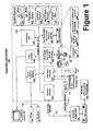
- Figure 1 illustrates an example of a suitable computing system environment 100 in which the invention may be implemented.
- the computing system environment 100 is only one example of a suitable computing environment and is not intended to suggest any limitation as to the scope of use or functionality of the invention. Neither should the computing environment 100 be interpreted as having any dependency or requirement relating to any one or combination of components illustrated in the exemplary operating environment 100.
- the invention is operational with numerous other general purpose or special purpose computing system environments or configurations.
- Examples of well known computing systems, environments, and/or configurations that may be suitable for use with the invention include, but are not limited to, personal computers, server computers, hand-held or laptop devices, multiprocessor systems, microprocessor-based systems, set top boxes, programmable consumer electronics, network PCs, minicomputers, mainframe computers, distributed computing environments that include any of the above systems or devices, and the like.
- the invention may be described in the general context of computer-executable instructions, such as program modules, being executed by a computer.
- program modules include routines, programs, objects, components, data structures, etc. that perform particular tasks or implement particular abstract data types.
- the invention may also be practiced in distributed computing environments where tasks are performed by remote processing devices that are linked through a communications network or other data transmission medium.
- program modules and other data may be located in both local and remote computer storage media including memory storage devices.
- an exemplary system for implementing the invention includes a general purpose computing device in the form of a computer 110.
- Components of computer 110 may include, but are not limited to, a processing unit 120, a system memory 130, and a system bus 121 that couples various system components including the system memory to the processing unit 120.
- the system bus 121 may be any of several types of bus structures including a memory bus or memory controller, a peripheral bus, and a local bus using any of a variety of bus architectures.
- such architectures include Industry Standard Architecture (ISA) bus, Micro Channel Architecture (MCA) bus, Enhanced ISA (EISA) bus, Video Electronics Standards Association (VESA) local bus, and Peripheral Component Interconnect (PCI) bus (also known as Mezzanine bus).
- ISA Industry Standard Architecture
- MCA Micro Channel Architecture
- EISA Enhanced ISA
- VESA Video Electronics Standards Association
- PCI Peripheral Component Interconnect
- Computer 110 typically includes a variety of computer readable media.
- Computer readable media can be any available media that can be accessed by computer 110 and includes both volatile and non-volatile media, removable and non-removable media.
- Computer readable media may comprise computer storage media and communication media.
- Computer storage media includes both volatile and non-volatile, removable and non-removable media implemented in any method or technology for storage of information such as computer readable instructions, data structures, program modules or other data.
- Computer storage media includes, but is not limited to, RAM, ROM, EEPROM, flash memory or other memory technology, CD-ROM, digital versatile disks (DVD) or other optical disk storage, magnetic cassettes, magnetic tape, magnetic disk storage or other magnetic storage devices, or any other medium which can be used to store the desired information and which can accessed by computer 110.
- Communication media typically embodies computer readable instructions, data structures, program modules or other data in a modulated data signal such as a carrier wave or other transport mechanism and includes any information delivery media.
- modulated data signal means a signal that has one or more of its characteristics set or changed in such a manner as to encode information in the signal.
- communication media includes wired media such as a wired network or direct-wired connection, and wireless media such as acoustic, RF, infrared and other wireless media. Combinations of any of the above should also be included within the scope of computer readable media.
- the system memory 130 includes computer storage media in the form of volatile and/or non-volatile memory such as ROM 131 and RAM 132.
- a basic input/output system 133 (BIOS), containing the basic routines that help to transfer information between elements within computer 110, such as during start-up, is typically stored in ROM 131.
- RAM 132 typically contains data and/or program modules that are immediately accessible to and/or presently being operated on by processing unit 120.
- Figure 1 illustrates operating system 134, application programs 135, other program modules 136, and program data 137.
- the computer 110 may also include other removable/non-removable, volatile/non-volatile computer storage media.
- Figure 1 illustrates a hard disk drive 140 that reads from or writes to non-removable, non-volatile magnetic media, a magnetic disk drive 151 that reads from or writes to a removable, non-volatile magnetic disk 152, and an optical disk drive 155 that reads from or writes to a removable, non-volatile optical disk 156, such as a CD-ROM or other optical media.
- removable/non-removable, volatile/non-volatile computer storage media that can be used in the exemplary operating environment include, but are not limited to, magnetic tape cassettes, flash memory cards, digital versatile disks, digital video tape, solid state RAM, solid state ROM, and the like.
- the hard disk drive 141 is typically connected to the system bus 121 through a non-removable memory interface such as interface 140, and magnetic disk drive 151 and optical disk drive 155 are typically connected to the system bus 121 by a removable memory interface, such as interface 150.
- hard disk drive 141 is illustrated as storing operating system 144, application programs 145, other program modules 146, and program data 147. Note that these components can either be the same as or different from operating system 134, application programs 135, other program modules 136, and program data 137. Operating system 144, application programs 145, other program modules 146, and program data 147 are given different numbers here to illustrate that, at a minimum, they are different copies.
- a user may enter commands and information into the computer 110 through input devices such as a keyboard 162 and pointing device 161, commonly referred to as a mouse, trackball or touch pad.
- Other input devices may include a microphone, joystick, game pad, satellite dish, scanner, or the like.
- These and other input devices are often connected to the processing unit 120 through a user input interface 160 that is coupled to the system bus, but may be connected by other interface and bus structures, such as a parallel port, game port or a universal serial bus (USB).
- a monitor 191 or other type of display device is also connected to the system bus 121 via an interface, such as a video interface 190.
- computers may also include other peripheral output devices such as speakers 197 and printer 196, which may be connected through an output peripheral interface 190.
- the computer 110 may operate in a networked environment using logical connections to one or more remote computers, such as a remote computer 180.
- the remote computer 180 may be a personal computer, a server, a router, a network PC, a peer device or other common network node, and typically includes many or all of the elements described above relative to the computer 110, although only a memory storage device 181 has been illustrated in Figure 1 .
- the logical connections depicted include a local area network (LAN) 171 and a wide area network (WAN) 173, but may also include other networks.
- LAN local area network
- WAN wide area network
- Such networking environments are commonplace in offices, enterprise-wide computer networks, intranets and the Intemet.
- the computer 110 When used in a LAN networking environment, the computer 110 is connected to the LAN 171 through a network interface or adapter 170. When used in a WAN networking environment, the computer 110 typically includes a modem 172 or other means for establishing communications over the WAN 173, such as the Internet.
- the modem 172 which may be internal or external, may be connected to the system bus 121 via the user input interface 160, or other appropriate mechanism.
- program modules depicted relative to the computer 110, or portions thereof may be stored in the remote memory storage device.
- Figure 1 illustrates remote application programs 185 as residing on memory device 181. It will be appreciated that the network connections shown are exemplary and other means of establishing a communications link between the computers may be used.
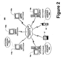
- FIG. 2 illustrates an exemplary network environment, with a server in communication with client computers via a network, in which the present invention may be employed.
- a number of servers 10a, 10b, etc. are interconnected via a communications network 14 (which may be a LAN, WAN, intranet, the Internet, or other computer network) with a number of client computers 20a, 20b, 20c, or computing devices, such as, mobile phone 15, land-line telephone 16, and personal digital assistant 17.
- a communications network 14 which may be a LAN, WAN, intranet, the Internet, or other computer network
- client computers 20a, 20b, 20c, or computing devices such as, mobile phone 15, land-line telephone 16, and personal digital assistant 17.
- the servers 10 can be Web servers with which the clients 20 communicate via any of a number of known protocols, such as, hypertext transfer protocol (HTTP) or wireless application protocol (WAP).
- HTTP hypertext transfer protocol
- WAP wireless application protocol
- Each client computer 20 can be equipped with browser 180a to gain access to the servers 10.
- personal digital assistant 17 can be equipped with browser 180b and mobile phone 15 can be equipped with browser 180c to display and receive various data.
- a user may interact with a computing application running on a client computing devices to monitor through the use of micro-monitor cooperating database environments.
- the reports may be stored on server computers and communicated to cooperating users through client computing devices over communications network 160.
- a user may monitor and manage data environments by interfacing with computing applications on client computing devices. The operations surrounding monitoring may be communicated by client computing devices to server computers for processing and storage. Server computers may host computing applications to facilitate the monitoring of data environments.
- the present invention can be utilized in a computer network environment having client computing devices for accessing and interacting with the network and a server computer for interacting with client computers.
- client computing devices for accessing and interacting with the network
- server computer for interacting with client computers.
- the systems and methods described herein can be implemented with a variety of network-based architectures, and thus should not be limited to the example shown. The herein described systems and methods will now be described in more detail with reference to a presently illustrative implementation.
- micro-monitoring extends the monitoring and administrating user experience by providing users a way to monitor server activity without having to maintain a full view of the monitoring application.
- micro-monitoring can be activated multiple ways in the standard monitoring UI. Either clicking from a menu, or clicking an icon in the toolbar will replace the full monitoring view with the micro-monitor.
- the micro-monitor provides high level bits of information: among others are the status of the user's publishers and-subscriptions, the sum of errors and warnings, brief messages displaying the most recent activity and a time stamp of when that activity occurred. The user can position this small window anywhere on the screen that is convenient.
- the micro-monitor provides a visual and audio alert.
- the user has the option to expand the micro-monitor and return it to the full view or opt to leave it in the current state.
- the micro-monitor will continue to function and monitor other activities. It will constantly maintain visual indicators to show that an error/warning has occurred and will reflect that state until the issue has been resolved. The user will also be able to gather limited information about the problem being reported without returning the window to the full size.
- the micro-monitor provides controls to control operations of the computing environments it is monitoring.
- the user is afforded a small formed-factor monitoring application which provides the benefits of full blown fully expanded monitoring computing applications.
- Such form factor is more easily used by administrators as the micro-monitor may be positioned as part of the display area of the administrator's monitoring computing environment.
- participating database administrators may choose to operate micro-monitor in conjunction with other computing applications and would be notified of errors immediately through the described graphics and/or sounds.
- the micro-monitor in the instance the micro-monitor is restored to the complete view, it may present a summary page that highlights the errors and warnings. Using the summary page, user is allowed to dig deeper into the application to gather more detailed information about the error or warning and/or to correct the defect.
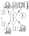
- FIG. 3 shows a system diagram of an exemplary database environment operating a micro-monitor in accordance with the herein described systems and methods.
- exemplary database environment 300 comprises DB Server1 maintaining Data Store 1, DB Server2 maintaining Data Store 2, DB Server3 maintaining Data Store 3, DB Server4 maintaining Data Store 4, communications network 14, Applications, and Administrator Client executing micro-monitor computing application 310.
- data for use by Applications 320 is communicated among any of DB Servers 1, 2, 3, or 4 across communications network 14 to Applications 320. It is appreciated that Applications 320 may operate on a various computing environments as indicated by the Applications residing computer server figure having a dashed outline.
- Micro-monitor application 310 operating on Administrator Client communicates with DB Servers 1, 2, 3, and 4 over communications network 14 to obtain monitoring database operational information for processing to generate monitoring information.
- DB Servers 1, 2, 3 and 3, maintaining Data Store 1, 2, 3, and 4 together form a single database being housed over four distinct computing environments.
- micro-monitor 310 operates to monitor the resulting distributed database (or in an alternative contemplated implementation, a replicated database) comprised of Data Stores 1, 2, 3, and 4.
- micro-monitor application 310 cooperates with the any underlying computing environment operating on DB Servers 1, 2, 3, and 4 on which Data Stores 1, 2, 3, and 4 operate.
- micro-monitor system 300 is described in a particular configuration having a particular configuration of computing environments, database servers, data stores, and communications networks, that such description is merely exemplary as the inventive concepts described herein extend to various computing environments having various databases and their associated components arranged in various configurations and operating differently from the provided description.
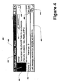
- FIG 4 is a enlarged screen shot of exemplary micro-monitor 400 when executed.
- micro-monitor 400 comprises graphical user interface 405 having display areas 410, 420, 430, 450 and controls 440, 470, 480, and 490.
- graphical user interface 405 accepts commands and inputs from participating users (not shown) through controls 440 and 470.
- control 440 when engaged works to indicate to exemplary micro-monitor 400 to expand graphical user interface 405 to conventional application size. In this occurrence, all of the information presently displayed on graphical user interface 405 will be displayed in the expanded, restored conventional computing application graphical user interface (as shown in Figure 5 ).
- Controls 470 and 480 when engaged operate to provide additional monitoring information than displayed in display areas 410, 420, 430, and 450.
- control 470 when engaged scrolls through the list of operational conditions for the monitored database environments (e.g. scrolls through an error list).
- control 480 when engaged, provides an expanded view transaction log(s) for the database environments being monitored. The expanded view may comprise higher priority activity that the micro monitor has been collecting.
- Control 490 is a dialog box which avails participating users to control and manage monitored errors.
- micro-monitor 400 cooperates with the database environments (not shown) and the computing environments operating systems on which the database environments operate to navigate the source of the error such that the error may be resolved.
- control 490 may serve as command line which sends commands from micro-monitor 490 to the database environments which are being monitored such that a displayed error may be resolved directly from micro-monitor 400.
- Display areas 410, 420, 420 and 450 may be configured to display a plethora of monitoring information.
- display area 410 is configured to display the information about the date and time of the last message received from the database environments being monitored.
- Display area 430 is configured to display the number of errors and warnings encountered during monitoring.
- Display area 420 is configured to provide a graphical display which indicates by color (not shown), and through the display of various graphics the operational state of the monitored database environments. In this context, if an error is encountered by the monitored database environment, display area may display a red graphic showing the number of the database server and/or data store on which the error occurs.
- Display area 450 shown as the largest, provides operational information about the database environments being observed. In the provided exemplary illustrative implementation, display area 450 is used to display error-type information about a cooperating database environment (not shown) being observed.
- micro-monitor 400 is described as having a particularly configured graphical user interface with specific display areas and controls, that such description is merely exemplary as the inventive concepts described herein extend various graphical user interfaces configured in a variety of ways and comprising the same, additional or fewer described components.
- FIG 4A is a screen shot of a conventional computing environment display area wherein a micro-monitor is being executed.
- conventional computing environment display area 480 comprises, for exemplary purposes, a word processing application.
- Micro-monitor 400 in full execution mode comprises but a fraction of the total available display area provided by a convention computing environment display area 480.
- the small form factor of micro-monitor 400 allows participating users (not shown) to operate other computing applications whilst performing the all important task of monitoring.
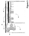
- FIG. 5 is a screen shot of an exemplary monitoring application 500.
- micro-monitor 400 may operate to expand into a conventional sized monitoring application 500.
- monitoring application 500 comprises graphical user interface 505 having display areas 510, 520, controls 530, and content 520 and 525.
- display area 520 comprises control content 520 which allows participating users (not shown) the ability to navigate through cooperating database environments (not shown).
- the data populated in micro-monitor 400 is populated in monitoring application 500 in display areas 510 and 520.
- the mapping of the content may be pre-configured such that content found in display area 430 (not shown) of micro-monitor 400 (not shown) may map to the content 525 of display area 520. Similarly, content found in display area 450 (not shown) may also map to content 525 of display area 520. Likewise controls 490 (not shown) may map to control content 520 of display area 510. Controls 530 may be employed to navigate and manage content 520 and 525 of display areas 510, and 520, respectively.
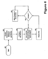
- FIG. 6 is a flow diagram of the processing performed when executing, configuring, and operating an exemplary micro-monitor.
- processing begins at block 600 and proceeds to block 605 where the customization settings for the micro-monitor are provided.
- Customization/configuration settings may comprise the location of micro-monitor display areas, and controls.
- Processing then proceeds to block 610 where the micro-monitor is configured according to the provided configuration settings.
- the micro-monitor then communicates with the cooperating database environments at block 615 to obtain the data required for monitoring.
- a check is then performed to determine if the changes to the database environment were received by the micro-monitor. If at block 625, it is determined that changes have been made, processing proceeds to block 630 where the received changes are made. If, however, at block 625 it is determined that there are no changes, processing reverts to block 615 and proceeds there from.
- the present invention may be implemented in a variety of computer environments (including both non-wireless and wireless computer environments), partial computing environments, and real world environments.
- the various techniques described herein may be implemented in hardware or software, or a combination of both.
- the techniques are implemented in computer programs executing on programmable computers that each include a processor, a storage medium readable by the processor (including volatile and non-volatile memory and/or storage elements), at least one input device, and at least one output device.
- Program code is applied to data entered using the input device to perform the functions described above and to generate output information.
- the output information is applied to one or more output devices.
- Each program is preferably implemented in a high level procedural or object oriented programming language to communicate with a computer system.
- the programs can be implemented in assembly or machine language, if desired.
- the language may be a compiled or interpreted language.
- Each such computer program is preferably stored on a storage medium or device (e.g., ROM or magnetic disk) that is readable by a general or special purpose programmable computer for configuring and operating the computer when the storage medium or device is read by the computer to perform the procedures described above.
- the system may also be considered to be implemented as a computer-readable storage medium, configured with a computer program, where the storage medium so configured causes a computer to operate in a specific and predefined manner.
Abstract
Description
- The invention generally relates to monitoring applications to monitor computing environments, and, more particularly, to a micro-monitor for use to monitor database environments that provide rich, robust, and customizable data.
- As computing and communications technologies have advanced, there has been and continues to be a globalization of market places and the expansion of business and governmental enterprises alike. The geographic limitations of sharing data and information across large spans are becoming a distant memory. Moreover, with these technological advances, computing applications which were once slated for use on stand alone machines are being deployed across, what are often, large computing environment networks and platforms. As more data and computing applications become shared, there arises a need to monitor and control the systems that house data to ensure that they are properly functioning and protect against unwanted down time which could translate into lost revenues.
- An enterprise's computing environment might contain hundreds of server computers and, possibly, thousands of client computers, all in communication to share applications and application data. Such computing environment might also support vast data stores for use to store application data. Today's data stores, or databases, are designed to operate on a single stand alone machine or among several computing machines (e.g. computer database servers) and cooperate with the computing environment to accept data for storage and/or to provide data to a requesting application. Given the importance of an enterprise's data, significant efforts have and are being made to ensure that the database management applications operating to store, manage, and retrieve the data are fully operational and fully optimal. In this context, database management application providers have developed monitoring applications which are in constant communication with the database management applications so that application errors may be monitored and resolved.
- A database monitoring application may be an independent application cooperating with the enterprise's computing environment or could be a component of the database management application which is utilized to monitor the various databases across the computing environment. In either case, the monitoring application operates to poll the database and associated applications for relevant operations, optimization, and communication information which may be processed by the monitoring application for display to computing environment administrators. Generally, the monitoring applications are full blown computing applications which when executed may provide a graphical user interface having various display areas to display various information about the database management applications. In addition, the graphical user interface may have navigation controls to assist in the manipulation of the displayed data.
- In practice, a database administrator launches the monitoring application (and associated graphical user interface). The monitoring application engages in communications with the database management applications and databases (e.g. data stores) it is to monitor. Using messaging services, the monitoring application requests specific data from the database management applications and databases (e.g. data stores) about the operational condition and state of the database management application and/or data store. This information may include communication integrity, transaction log information, processing integrity and efficiency. Processing the retrieved information, the monitoring application, using some predefined user defined configuration variables (e.g. flag indicators and warning condition thresholds), generates monitoring information for display on the monitoring application's graphical user interface display area.
- Often the graphical user interface of the monitoring application takes up the same display space as any other computing application operating on the administrators computer, such as a word processing computing application, a spreadsheet, or e-mail computing application. As such, the monitoring application is cumbersome to operate the administrator must constantly switch back between the monitoring application and other computing applications (e.g. word processor, e-mail application,) to keep on top of monitoring application reports and alerts. Moreover, administrators cannot dispose of the monitoring application as it provides crucial performance and operations data required to maintain the integrity of the database management applications being monitored.
- Moreover it is known from
EP A 0 660 212 - In addition
US A 5 838 321 descnbes a computer program operating with a graphical user interface (GUI) capable of linking or embedding an object from an application program into the GUI The program is described to include instructions for determining a size of an object Furthermore, the computer program is described to adjust the location of the object on the display when the object is in an active mode, to provide space for controls of the object's server application and to provide appropriate pop-up menus for the object - In view of the deficiencies of the prior art it is the object of the invention to provide improved methods and systems for monitoring computing and in particular database environments
- This object is solved by the claimed subject matter
- Preferred embodiments are subject to the depended claims
- A micro-monitor for use in the monitoring of database environments is provided. In an illustrative implementation, a micro-monitor comprises a graphical user interface (GUI) having controls for navigation of information, controls to control database environments, and a display area for displaying monitoring information about the database information. The micro-monitor also comprises controls to maximize the display area of the micro-monitor as if it were a regular computing application. When executed in computing environment having an operating display space, the micro-monitor occupies a fraction of the operating display space which is occupied by other executing computing applications. In operation, the micro-monitor, through the GUI, accepts configuration variables for use to set monitoring thresholds, alarms, and display layout. Based on the configuration information, the micro-monitor will cooperate with the database environments which it is monitoring to obtain operational information for processing. The operational information is processed according to the configuration to generate desired monitoring information for display in the micro-monitor display area.
- In an alternative contemplated implementation, the micro-monitor comprises a smaller form-factor of a conventional monitoring computing application. The smaller form-resulting in the micro-monitor, when executed in a computing environment having an operating display area, occupies less space than other executing computing applications operating on the computing environment. The micro-monitor, in this context, comprises controls to navigate through monitoring information, as well as, controls for controlling operations on the database environment.
- Other features are described in more detail below.
- The herein described systems and methods are further described with reference to the accompanying drawings in which:
-
Figures 1 and2 are schematic illustrations of exemplary computing environments suitable for the present invention, withFigure 2 depicting an exemplary networked computing environment; -
Figure 3 is a block diagram of a micro-monitor system and the cooperation between its components; -
Figure 4 is a screen shot of an exemplary micro-monitor; -
Figure 5 is a screen shot of an exemplary monitor on which the micro-monitor is based; and -
Figure 6 is a flowchart diagram of the processing performed by the micro-monitor to perform monitoring functions. - A technique is provided wherein monitoring software is divided between a monitored server and a monitoring user computer, with the server portion of the software configured to reply, to a query from the monitoring user computer, with a compilation of information about the server and software services running on the server. Queries are sent periodically and are separated by a predefined time interval. In addition, the server portion of the software may operate to send messages to participating users upon the occurrence of a deficiency or other pre-defined condition.
- Information about the server is sent in a single compilation, allowing the monitoring user computer to avoid having to send repeated queries to the server to gather necessary information from the server. Servers that are not connected to the network, i.e., are without power or are not running network connectivity software properly, can be detected. Subsequent to a discovery of a deficiency on the server, the display provided to the user will change to indicate the occurrence of a deficiency. The user computer portion of the software can monitor multiple servers. The selection of the server's services to be monitored by the monitoring software is determined by the server portion of the monitoring software; thus, changing the selection of the services to be monitored on a server requires no change to the user computer portion of the monitoring software.
- In one aspect, the herein described methods provide a method of monitoring a server computer, the method including compiling at the server computer a collection of information about the status of the server computer, the collection including a plurality of status indicators, sending a query to the server computer from a user computer, and sending a reply from the server computer to the user computer, the reply including the collection.
- The collection may include information about a deficiency at the server or other servers in the computing environment. The reply may include information directed to be included in the reply by a configuration setting at the server. A participating user computer may send a query to each of a plurality of servers and may receive a reply from each of the plurality of servers.
- In another aspect, herein described methods provide a method of monitoring a server computer, the method including sending a plurality of queries for information about the server computer, the queries being sent at an adjustable frequency, each query being sent to the server computer from a user computer, compiling the information in a reply to one of the queries, sending the reply from the server computer to the user computer and, based on the reply, adjusting the display of information to participating users.
- Implementations of this aspect may include one or more of the following features. The reply may include information about a deficiency at the server computer and the frequency may be increased as a result of the deficiency. The reply may include the status of a software service at the server computer or information directed to be included in the reply by a configuration setting at the server computer.
- The method may further include using a plurality of lists of server computers, wherein each list corresponds to a different frequency of sending queries. The method may further include determining from the reply whether a deficiency exists at the server computer and depending on the outcome of that determination, moving a list entry for the server computer, the list entry being moved from one of the lists of server computers to another of the lists of server computers. Moving the list entry may further depend on a configuration setting.
-
Figure 1 illustrates an example of a suitablecomputing system environment 100 in which the invention may be implemented. Thecomputing system environment 100 is only one example of a suitable computing environment and is not intended to suggest any limitation as to the scope of use or functionality of the invention. Neither should thecomputing environment 100 be interpreted as having any dependency or requirement relating to any one or combination of components illustrated in theexemplary operating environment 100. - The invention is operational with numerous other general purpose or special purpose computing system environments or configurations. Examples of well known computing systems, environments, and/or configurations that may be suitable for use with the invention include, but are not limited to, personal computers, server computers, hand-held or laptop devices, multiprocessor systems, microprocessor-based systems, set top boxes, programmable consumer electronics, network PCs, minicomputers, mainframe computers, distributed computing environments that include any of the above systems or devices, and the like.
- The invention may be described in the general context of computer-executable instructions, such as program modules, being executed by a computer. Generally, program modules include routines, programs, objects, components, data structures, etc. that perform particular tasks or implement particular abstract data types. The invention may also be practiced in distributed computing environments where tasks are performed by remote processing devices that are linked through a communications network or other data transmission medium. In a distributed computing environment, program modules and other data may be located in both local and remote computer storage media including memory storage devices.
- With reference to
Figure 1 , an exemplary system for implementing the invention includes a general purpose computing device in the form of a computer 110. Components of computer 110 may include, but are not limited to, aprocessing unit 120, asystem memory 130, and a system bus 121 that couples various system components including the system memory to theprocessing unit 120. The system bus 121 may be any of several types of bus structures including a memory bus or memory controller, a peripheral bus, and a local bus using any of a variety of bus architectures. By way of example, and not limitation, such architectures include Industry Standard Architecture (ISA) bus, Micro Channel Architecture (MCA) bus, Enhanced ISA (EISA) bus, Video Electronics Standards Association (VESA) local bus, and Peripheral Component Interconnect (PCI) bus (also known as Mezzanine bus). - Computer 110 typically includes a variety of computer readable media. Computer readable media can be any available media that can be accessed by computer 110 and includes both volatile and non-volatile media, removable and non-removable media. By way of example, and not limitation, computer readable media may comprise computer storage media and communication media. Computer storage media includes both volatile and non-volatile, removable and non-removable media implemented in any method or technology for storage of information such as computer readable instructions, data structures, program modules or other data. Computer storage media includes, but is not limited to, RAM, ROM, EEPROM, flash memory or other memory technology, CD-ROM, digital versatile disks (DVD) or other optical disk storage, magnetic cassettes, magnetic tape, magnetic disk storage or other magnetic storage devices, or any other medium which can be used to store the desired information and which can accessed by computer 110. Communication media typically embodies computer readable instructions, data structures, program modules or other data in a modulated data signal such as a carrier wave or other transport mechanism and includes any information delivery media. The term "modulated data signal" means a signal that has one or more of its characteristics set or changed in such a manner as to encode information in the signal. By way of example, and not limitation, communication media includes wired media such as a wired network or direct-wired connection, and wireless media such as acoustic, RF, infrared and other wireless media. Combinations of any of the above should also be included within the scope of computer readable media.
- The
system memory 130 includes computer storage media in the form of volatile and/or non-volatile memory such as ROM 131 andRAM 132. A basic input/output system 133 (BIOS), containing the basic routines that help to transfer information between elements within computer 110, such as during start-up, is typically stored in ROM 131.RAM 132 typically contains data and/or program modules that are immediately accessible to and/or presently being operated on by processingunit 120. By way of example, and not limitation,Figure 1 illustratesoperating system 134,application programs 135,other program modules 136, andprogram data 137. - The computer 110 may also include other removable/non-removable, volatile/non-volatile computer storage media. By way of example only,
Figure 1 illustrates ahard disk drive 140 that reads from or writes to non-removable, non-volatile magnetic media, amagnetic disk drive 151 that reads from or writes to a removable, non-volatilemagnetic disk 152, and anoptical disk drive 155 that reads from or writes to a removable, non-volatileoptical disk 156, such as a CD-ROM or other optical media. Other removable/non-removable, volatile/non-volatile computer storage media that can be used in the exemplary operating environment include, but are not limited to, magnetic tape cassettes, flash memory cards, digital versatile disks, digital video tape, solid state RAM, solid state ROM, and the like. Thehard disk drive 141 is typically connected to the system bus 121 through a non-removable memory interface such asinterface 140, andmagnetic disk drive 151 andoptical disk drive 155 are typically connected to the system bus 121 by a removable memory interface, such asinterface 150. - The drives and their associated computer storage media, discussed above and illustrated in
Figure 1 , provide storage of computer readable instructions, data structures, program modules and other data for the computer 110. InFigure 1 , for example,hard disk drive 141 is illustrated as storingoperating system 144,application programs 145, other program modules 146, andprogram data 147. Note that these components can either be the same as or different fromoperating system 134,application programs 135,other program modules 136, andprogram data 137.Operating system 144,application programs 145, other program modules 146, andprogram data 147 are given different numbers here to illustrate that, at a minimum, they are different copies. A user may enter commands and information into the computer 110 through input devices such as a keyboard 162 andpointing device 161, commonly referred to as a mouse, trackball or touch pad. Other input devices (not shown) may include a microphone, joystick, game pad, satellite dish, scanner, or the like. These and other input devices are often connected to theprocessing unit 120 through auser input interface 160 that is coupled to the system bus, but may be connected by other interface and bus structures, such as a parallel port, game port or a universal serial bus (USB). Amonitor 191 or other type of display device is also connected to the system bus 121 via an interface, such as avideo interface 190. In addition to the monitor, computers may also include other peripheral output devices such asspeakers 197 andprinter 196, which may be connected through an outputperipheral interface 190. - The computer 110 may operate in a networked environment using logical connections to one or more remote computers, such as a
remote computer 180. Theremote computer 180 may be a personal computer, a server, a router, a network PC, a peer device or other common network node, and typically includes many or all of the elements described above relative to the computer 110, although only amemory storage device 181 has been illustrated inFigure 1 . The logical connections depicted include a local area network (LAN) 171 and a wide area network (WAN) 173, but may also include other networks. Such networking environments are commonplace in offices, enterprise-wide computer networks, intranets and the Intemet. - When used in a LAN networking environment, the computer 110 is connected to the
LAN 171 through a network interface oradapter 170. When used in a WAN networking environment, the computer 110 typically includes amodem 172 or other means for establishing communications over theWAN 173, such as the Internet. Themodem 172, which may be internal or external, may be connected to the system bus 121 via theuser input interface 160, or other appropriate mechanism. In a networked environment, program modules depicted relative to the computer 110, or portions thereof, may be stored in the remote memory storage device. By way of example, and not limitation,Figure 1 illustrates remote application programs 185 as residing onmemory device 181. It will be appreciated that the network connections shown are exemplary and other means of establishing a communications link between the computers may be used. -
Computer environment 100, described above, can be deployed as part of a computer network. In general, the above description for computers applies to both server computers and client computers deployed in a network environment.Figure 2 illustrates an exemplary network environment, with a server in communication with client computers via a network, in which the present invention may be employed. As shown inFigure 2 , a number ofservers mobile phone 15, land-line telephone 16, and personaldigital assistant 17. In a network environment in which thecommunications network 160 is the Internet, for example, theservers 10 can be Web servers with which the clients 20 communicate via any of a number of known protocols, such as, hypertext transfer protocol (HTTP) or wireless application protocol (WAP). Each client computer 20 can be equipped withbrowser 180a to gain access to theservers 10. Similarly, personaldigital assistant 17 can be equipped withbrowser 180b andmobile phone 15 can be equipped withbrowser 180c to display and receive various data. - In operation, a user (not shown) may interact with a computing application running on a client computing devices to monitor through the use of micro-monitor cooperating database environments. The reports may be stored on server computers and communicated to cooperating users through client computing devices over
communications network 160. A user may monitor and manage data environments by interfacing with computing applications on client computing devices. The operations surrounding monitoring may be communicated by client computing devices to server computers for processing and storage. Server computers may host computing applications to facilitate the monitoring of data environments. - Thus, the present invention can be utilized in a computer network environment having client computing devices for accessing and interacting with the network and a server computer for interacting with client computers. However, the systems and methods described herein can be implemented with a variety of network-based architectures, and thus should not be limited to the example shown. The herein described systems and methods will now be described in more detail with reference to a presently illustrative implementation.
- In an illustrative implementation, micro-monitoring extends the monitoring and administrating user experience by providing users a way to monitor server activity without having to maintain a full view of the monitoring application. In operation, micro-monitoring can be activated multiple ways in the standard monitoring UI. Either clicking from a menu, or clicking an icon in the toolbar will replace the full monitoring view with the micro-monitor. The micro-monitor provides high level bits of information: among others are the status of the user's publishers and-subscriptions, the sum of errors and warnings, brief messages displaying the most recent activity and a time stamp of when that activity occurred. The user can position this small window anywhere on the screen that is convenient.
- As a result the user has additional computing operating display space for other separate activities while allowing a high level, dynamic view of the monitor to remain visible. When an error or warning occurs, the micro-monitor provides a visual and audio alert. The user has the option to expand the micro-monitor and return it to the full view or opt to leave it in the current state. Just like the standard full view, the micro-monitor will continue to function and monitor other activities. It will constantly maintain visual indicators to show that an error/warning has occurred and will reflect that state until the issue has been resolved. The user will also be able to gather limited information about the problem being reported without returning the window to the full size. In addition, the micro-monitor provides controls to control operations of the computing environments it is monitoring. In this context, the user is afforded a small formed-factor monitoring application which provides the benefits of full blown fully expanded monitoring computing applications. Such form factor is more easily used by administrators as the micro-monitor may be positioned as part of the display area of the administrator's monitoring computing environment. Additionally, as the contemplated micro-monitor is capable of displaying graphics and sounds, participating database administrators may choose to operate micro-monitor in conjunction with other computing applications and would be notified of errors immediately through the described graphics and/or sounds.
- In the contemplated implementation, in the instance the micro-monitor is restored to the complete view, it may present a summary page that highlights the errors and warnings. Using the summary page, user is allowed to dig deeper into the application to gather more detailed information about the error or warning and/or to correct the defect.
-
Figure 3 shows a system diagram of an exemplary database environment operating a micro-monitor in accordance with the herein described systems and methods. As shownexemplary database environment 300 comprises DB Server1 maintainingData Store 1, DB Server2 maintainingData Store 2, DB Server3 maintainingData Store 3, DB Server4 maintaining Data Store 4,communications network 14, Applications, and Administrator Client executingmicro-monitor computing application 310. In operation, data for use byApplications 320 is communicated among any ofDB Servers communications network 14 toApplications 320. It is appreciated thatApplications 320 may operate on a various computing environments as indicated by the Applications residing computer server figure having a dashed outline. -
Micro-monitor application 310 operating on Administrator Client communicates withDB Servers communications network 14 to obtain monitoring database operational information for processing to generate monitoring information.DB Servers Data Store Data Stores Data Stores micro-monitor application 310 cooperates with the any underlying computing environment operating onDB Servers Data Stores - It is appreciated that although
micro-monitor system 300 is described in a particular configuration having a particular configuration of computing environments, database servers, data stores, and communications networks, that such description is merely exemplary as the inventive concepts described herein extend to various computing environments having various databases and their associated components arranged in various configurations and operating differently from the provided description. -
Figure 4 is a enlarged screen shot of exemplary micro-monitor 400 when executed. As is seen inFigure 4 , micro-monitor 400 comprisesgraphical user interface 405 havingdisplay areas graphical user interface 405 accepts commands and inputs from participating users (not shown) throughcontrols control 440 when engaged works to indicate to exemplary micro-monitor 400 to expandgraphical user interface 405 to conventional application size. In this occurrence, all of the information presently displayed ongraphical user interface 405 will be displayed in the expanded, restored conventional computing application graphical user interface (as shown inFigure 5 ).Controls display areas control 470, when engaged scrolls through the list of operational conditions for the monitored database environments (e.g. scrolls through an error list). Comparatively,control 480, when engaged, provides an expanded view transaction log(s) for the database environments being monitored. The expanded view may comprise higher priority activity that the micro monitor has been collecting.Control 490 is a dialog box which avails participating users to control and manage monitored errors. In this context whencontrol 490 is engaged, micro-monitor 400 cooperates with the database environments (not shown) and the computing environments operating systems on which the database environments operate to navigate the source of the error such that the error may be resolved. Alternatively,control 490 may serve as command line which sends commands from micro-monitor 490 to the database environments which are being monitored such that a displayed error may be resolved directly frommicro-monitor 400. -
Display areas display area 410 is configured to display the information about the date and time of the last message received from the database environments being monitored.Display area 430, is configured to display the number of errors and warnings encountered during monitoring.Display area 420 is configured to provide a graphical display which indicates by color (not shown), and through the display of various graphics the operational state of the monitored database environments. In this context, if an error is encountered by the monitored database environment, display area may display a red graphic showing the number of the database server and/or data store on which the error occurs.Display area 450, shown as the largest, provides operational information about the database environments being observed. In the provided exemplary illustrative implementation,display area 450 is used to display error-type information about a cooperating database environment (not shown) being observed. - It is appreciated that although
micro-monitor 400 is described as having a particularly configured graphical user interface with specific display areas and controls, that such description is merely exemplary as the inventive concepts described herein extend various graphical user interfaces configured in a variety of ways and comprising the same, additional or fewer described components. -
Figure 4A is a screen shot of a conventional computing environment display area wherein a micro-monitor is being executed. As is shown inFigure 4A , conventional computingenvironment display area 480 comprises, for exemplary purposes, a word processing application. Micro-monitor 400 in full execution mode comprises but a fraction of the total available display area provided by a convention computingenvironment display area 480. The small form factor ofmicro-monitor 400 allows participating users (not shown) to operate other computing applications whilst performing the all important task of monitoring. -
Figure 5 is a screen shot of anexemplary monitoring application 500. As described inFigure 4 , micro-monitor 400 (not shown) may operate to expand into a conventionalsized monitoring application 500. As is shown inFigure 5 ,monitoring application 500 comprisesgraphical user interface 505 havingdisplay areas content display area 520 comprisescontrol content 520 which allows participating users (not shown) the ability to navigate through cooperating database environments (not shown). In operation, when micro-monitor 400 (not shown) is expanded into conventionalsized monitoring application 500, the data populated in micro-monitor 400 (not shown) is populated inmonitoring application 500 indisplay areas content 525 ofdisplay area 520. Similarly, content found in display area 450 (not shown) may also map to content 525 ofdisplay area 520. Likewise controls 490 (not shown) may map to controlcontent 520 ofdisplay area 510.Controls 530 may be employed to navigate and managecontent display areas -
Figure 6 is a flow diagram of the processing performed when executing, configuring, and operating an exemplary micro-monitor. As shown, processing begins atblock 600 and proceeds to block 605 where the customization settings for the micro-monitor are provided. Customization/configuration settings may comprise the location of micro-monitor display areas, and controls. Processing then proceeds to block 610 where the micro-monitor is configured according to the provided configuration settings. The micro-monitor then communicates with the cooperating database environments atblock 615 to obtain the data required for monitoring. A check is then performed to determine if the changes to the database environment were received by the micro-monitor. If atblock 625, it is determined that changes have been made, processing proceeds to block 630 where the received changes are made. If, however, atblock 625 it is determined that there are no changes, processing reverts to block 615 and proceeds there from. - The herein described systems and methods provide a micro-monitor for use to monitor database environments. It is understood, however, that the invention is susceptible to various modifications and alternative constructions. The invention is intended to cover all modifications, alternative constructions, and equivalents falling within the scope of the invention.
- It should also be noted that the present invention may be implemented in a variety of computer environments (including both non-wireless and wireless computer environments), partial computing environments, and real world environments. The various techniques described herein may be implemented in hardware or software, or a combination of both. Preferably, the techniques are implemented in computer programs executing on programmable computers that each include a processor, a storage medium readable by the processor (including volatile and non-volatile memory and/or storage elements), at least one input device, and at least one output device. Program code is applied to data entered using the input device to perform the functions described above and to generate output information. The output information is applied to one or more output devices. Each program is preferably implemented in a high level procedural or object oriented programming language to communicate with a computer system. However, the programs can be implemented in assembly or machine language, if desired. In any case, the language may be a compiled or interpreted language. Each such computer program is preferably stored on a storage medium or device (e.g., ROM or magnetic disk) that is readable by a general or special purpose programmable computer for configuring and operating the computer when the storage medium or device is read by the computer to perform the procedures described above. The system may also be considered to be implemented as a computer-readable storage medium, configured with a computer program, where the storage medium so configured causes a computer to operate in a specific and predefined manner.
- Although an exemplary implementation of the invention has been described in detail above, those skilled in the art will readily appreciate that many additional modifications are possible in the exemplary embodiments without materially departing from the novel teachings and advantages of the invention as defined by the following claims.
Claims (25)
- A method for providing a micro-monitor for use to monitor database environments without having to maintain a full view of the monitoring application, comprising:providing a monitoring application (310), the monitoring application comprising a first GUI (400) and a second GUI (500), the first GUI, a micro-monitor (405), having at least controls to control operations of the database environments (300), visual indicators to show that an error has occurred, error-type information (450), and controls (470) that when engaged allow to resolve the error by scrolling through an error list, such that the size of the micro-monitor in full execution mode is a small fraction of the total size of the total available display area provided by a conventional computing environment display area (485), while allowing a high level view of the monitoring application to remain visible and to perform all important tasks of monitoring;in response to engaging a control of the micro-monitor expanding the micro-monitor into the second GUI (500), a conventionally sized computing application graphical user interface (505), providing a full view of the monitoring application that displays all of the information displayed on the micro-monitor and maps the controls that when engaged allow to resolve the error (490) to control content, providing at least a summary page highlighting errors and warnings allowing to correct a defect;providing a communication means, the communication means used by the micro-monitor to communicate with cooperating database environments by sending a plurality of queries for information the queries being sent at a frequency, and receiving replies to the queries used to adjust the display of information.
- The method as recited in claim 1, further comprising providing size adjustment controls (440) for the micro-monitor application (310), wherein the controls perform the task of expanding the size of the micro-monitor.
- The method as recited in claim 1, further comprising providing command line controls (490) for the micro-monitor application (310), wherein the command line controls allow the micro-monitor (400) to control one or more operations of the cooperating database environments (300).
- The method as recited in claim 3, further comprising providing navigation controls (490) for the micro-monitor application (310) that allow users to obtain detailed monitoring information.
- The method as recited in claim 1, further comprising providing graphic alerts (420) through micro-monitor application (310) representative of database environment operational states.
- The method as recited in claim 4, further comprising providing sound alerts through micro-monitor application (310) representative of database environment operational states.
- The method as recited in claim 1, further comprising:communicating by the micro-monitor (400) with the database environment (300) to obtain database environment operational information;processing the received database environment operational information to generate monitoring information;displaying the generated monitoring information in the micro-monitor.
- The method as recited in claim 7, further comprising controlling the database environment (300) by the micro-monitor (400) through communication by the micro-monitor of command statements to the computing environment.
- The method as recited in claim 7, further comprising the navigating through the monitoring information displayed in the micro-monitor (400) through the use of micro-monitor controls (490).
- The method as recited in claim 7, further comprising displaying graphical notices of computing environments in the micro-monitor (400).
- The method as recited in claim 7, further comprising broadcasting a aural notices representative of computing environment (300) errors by the micro-monitor (400).
- A computer readable medium having stored thereon computer readable instructions that when executed on a computer are configure to perform any one of the methods as recited in claim 1 to 11.
- A system for a micro-monitor for use to monitor a database environment without having to maintain a full view of the monitoring application comprising:a monitoring application (310), the monitoring application comprising a first GUI (400) and a second GUI (500),a micro-monitor (400), the first GUI, having at least controls to control operations of the database environment (300), visual indicators to show that an error has occurred, error-type information (450), and controls (470) that when engaged allow to resolve the error by scrolling through an error list, such that the micro-monitor in full execution mode has a small size in relation to the total available display space (485) provided by a conventional computing environment display area (485), while allowing a high level view of the monitoring application to remain visible and to perform all important tasks of monitoring;a conventionally sized monitor (500), the second GUI, wherein the micro-monitor in response to engaging a control of the micro-monitor operates to expand into the conventionally sized monitor, providing a full view of the monitoring application that displays all of the information displayed on the micro-monitor and maps the controls that when engaged allow to resolve the error (490) to control content, providing at least a summary page highlighting errors and warnings allowing to correct a defect; anda communications means, the communications means used by the micro-monitor to communicate data to and from the computing environment (300) by periodically sending queries and receiving replies used to adjust the display of information.
- The system as recited in claim 13, wherein the micro-monitor (400) comprises a plurality of display areas (420-450) for use to display monitoring information.
- The system as recited in claim 14, wherein the micro-monitor (400) comprises command controls (490) allowing the micro-monitor to perform at least one operation on the computing environment (300).
- The system as recited in claim 15, wherein the micro-monitor (400) is expandable to a larger size (500).
- The system as recited in claim 13, wherein the micro-monitor (400) generates graphical (420) and aural notices representative of at least one error occurring in the computing environment (300).
- The system as recited in claim 13, further comprising a user interface, UI (400), for monitoring activities of a computing environment (300), wherein the UI comprises:a set of information (450) representative of one or more components of the computing environment;wherein the UI is displayable is a plurality of forms (400, 500) configurable to present one or more computing environment information, the UI providing control over the computing environment.
- The system as recited in claim 18, wherein the UI (400) is displayable in a large form factor (500) and a small form factor (400), wherein the a large form factor occupies a substantial portion of a cooperating computing environment's display area and wherein the small form factor occupies a small fraction of a computing environment's display area (485).
- The system as recited in claim 19, wherein the UI (400) operating in the small form factor has controls (440) to expand the UI from a small form factor to the large form factor.
- The system as recited in claim 20, wherein when the UI (400) is expanded from the small form factor to the large form factor (500), the information populating the small form factor UI is used to populate the large form factor UI.
- The system as recited in claim 19, wherein the UI (400) operating in the small form factor comprises a plurality of display areas (410-450) capable of displaying monitoring information,
wherein the monitoring information comprises dynamic links which when engaged navigate to the portion of the computing environment (300) being monitored. - The system as recited in claim 22, wherein the monitoring information (450) comprises error information about the computing environment (300) being monitored.
- The system as recited in claim 23, further comprising command line controls (490).
- The system as recited in claim 24, wherein the command line controls (490) communicates commands to the monitored computing environment (300) to perform at least one operation on the monitored computing environment.
Applications Claiming Priority (2)
| Application Number | Priority Date | Filing Date | Title |
|---|---|---|---|
| US608481 | 1984-05-09 | ||
| US10/608,481 US7272795B2 (en) | 2003-06-27 | 2003-06-27 | Micro-monitor to monitor database environments |
Publications (2)
| Publication Number | Publication Date |
|---|---|
| EP1491998A1 EP1491998A1 (en) | 2004-12-29 |
| EP1491998B1 true EP1491998B1 (en) | 2009-04-15 |
Family
ID=33418729
Family Applications (1)
| Application Number | Title | Priority Date | Filing Date |
|---|---|---|---|
| EP04014010A Not-in-force EP1491998B1 (en) | 2003-06-27 | 2004-06-15 | Micro-monitor to monitor database environments |
Country Status (7)
| Country | Link |
|---|---|
| US (1) | US7272795B2 (en) |
| EP (1) | EP1491998B1 (en) |
| JP (1) | JP4541764B2 (en) |
| KR (1) | KR101008412B1 (en) |
| CN (1) | CN1609790B (en) |
| AT (1) | ATE428969T1 (en) |
| DE (1) | DE602004020544D1 (en) |
Families Citing this family (14)
| Publication number | Priority date | Publication date | Assignee | Title |
|---|---|---|---|---|
| US20070112512A1 (en) * | 1987-09-28 | 2007-05-17 | Verizon Corporate Services Group Inc. | Methods and systems for locating source of computer-originated attack based on GPS equipped computing device |
| US8631493B2 (en) * | 2004-08-12 | 2014-01-14 | Verizon Patent And Licensing Inc. | Geographical intrusion mapping system using telecommunication billing and inventory systems |
| US8572734B2 (en) | 2004-08-12 | 2013-10-29 | Verizon Patent And Licensing Inc. | Geographical intrusion response prioritization mapping through authentication and flight data correlation |
| US8082506B1 (en) * | 2004-08-12 | 2011-12-20 | Verizon Corporate Services Group Inc. | Geographical vulnerability mitigation response mapping system |
| US8091130B1 (en) | 2004-08-12 | 2012-01-03 | Verizon Corporate Services Group Inc. | Geographical intrusion response prioritization mapping system |
| US8418246B2 (en) * | 2004-08-12 | 2013-04-09 | Verizon Patent And Licensing Inc. | Geographical threat response prioritization mapping system and methods of use |
| US7954062B2 (en) * | 2005-01-03 | 2011-05-31 | International Business Machines Corporation | Application status board mitigation system and method |
| US8452756B2 (en) | 2006-11-09 | 2013-05-28 | International Business Machines Corporation | Database execution detail repository |
| US9008617B2 (en) * | 2006-12-28 | 2015-04-14 | Verizon Patent And Licensing Inc. | Layered graphical event mapping |
| US20090070743A1 (en) * | 2007-09-10 | 2009-03-12 | Unisys Corporation | System and method for analyzing software applications |
| US7486196B1 (en) | 2008-04-14 | 2009-02-03 | International Business Machines Corporation | Using audio to detect changes to the performance of an application |
| US10007651B2 (en) * | 2012-02-17 | 2018-06-26 | Jens Straten | Detect errors in intermediate electronic documents |
| US20150160627A1 (en) * | 2013-12-05 | 2015-06-11 | Dell Products L.P. | Methods and systems for monitoring and management in a distributed architecture information handling system chassis |
| EP3374840B1 (en) * | 2016-12-27 | 2022-08-10 | Drägerwerk AG & Co. KGaA | Display monitors and monitor mount |
Citations (1)
| Publication number | Priority date | Publication date | Assignee | Title |
|---|---|---|---|---|
| US5721853A (en) * | 1995-04-28 | 1998-02-24 | Ast Research, Inc. | Spot graphic display element with open locking and periodic animation |
Family Cites Families (11)
| Publication number | Priority date | Publication date | Assignee | Title |
|---|---|---|---|---|
| US5542040A (en) | 1993-12-15 | 1996-07-30 | International Business Machines Corporation | Display of dynamic data as a notebook |
| FR2717282B1 (en) * | 1994-03-10 | 1996-04-05 | Bull Sa | System analysis method. |
| US5838321A (en) | 1996-05-06 | 1998-11-17 | Ast Research, Inc. | User interface with embedded objects for personal computers and the like |
| US5933141A (en) * | 1998-01-05 | 1999-08-03 | Gateway 2000, Inc. | Mutatably transparent displays |
| US6067477A (en) * | 1998-01-15 | 2000-05-23 | Eutech Cybernetics Pte Ltd. | Method and apparatus for the creation of personalized supervisory and control data acquisition systems for the management and integration of real-time enterprise-wide applications and systems |
| US6538665B2 (en) * | 1999-04-15 | 2003-03-25 | Apple Computer, Inc. | User interface for presenting media information |
| JP2001092702A (en) * | 1999-09-20 | 2001-04-06 | Fujitsu Ltd | Information processing system, server device, client device and recording medium |
| US6564174B1 (en) * | 1999-09-29 | 2003-05-13 | Bmc Software, Inc. | Enterprise management system and method which indicates chaotic behavior in system resource usage for more accurate modeling and prediction |
| JP2002041465A (en) * | 1999-11-22 | 2002-02-08 | Mitsubishi Electric Corp | Communication system, database server, controller, processing terminal, relay server and manufacturing method of semiconductor device |
| US20010034732A1 (en) | 2000-02-17 | 2001-10-25 | Mark Vorholt | Architecture and method for deploying remote database administration |
| US6772411B2 (en) * | 2000-12-01 | 2004-08-03 | Bmc Software, Inc. | Software performance and management system |
-
2003
- 2003-06-27 US US10/608,481 patent/US7272795B2/en active Active
-
2004
- 2004-06-03 JP JP2004166379A patent/JP4541764B2/en not_active Expired - Fee Related
- 2004-06-15 EP EP04014010A patent/EP1491998B1/en not_active Not-in-force
- 2004-06-15 DE DE602004020544T patent/DE602004020544D1/en active Active
- 2004-06-15 AT AT04014010T patent/ATE428969T1/en not_active IP Right Cessation
- 2004-06-25 KR KR1020040048269A patent/KR101008412B1/en not_active IP Right Cessation
- 2004-06-25 CN CN2004100639929A patent/CN1609790B/en not_active Expired - Fee Related
Patent Citations (1)
| Publication number | Priority date | Publication date | Assignee | Title |
|---|---|---|---|---|
| US5721853A (en) * | 1995-04-28 | 1998-02-24 | Ast Research, Inc. | Spot graphic display element with open locking and periodic animation |
Also Published As
| Publication number | Publication date |
|---|---|
| EP1491998A1 (en) | 2004-12-29 |
| ATE428969T1 (en) | 2009-05-15 |
| JP4541764B2 (en) | 2010-09-08 |
| KR20050001467A (en) | 2005-01-06 |
| US20040267826A1 (en) | 2004-12-30 |
| CN1609790B (en) | 2010-05-26 |
| JP2005018752A (en) | 2005-01-20 |
| KR101008412B1 (en) | 2011-01-14 |
| US7272795B2 (en) | 2007-09-18 |
| DE602004020544D1 (en) | 2009-05-28 |
| CN1609790A (en) | 2005-04-27 |
Similar Documents
| Publication | Publication Date | Title |
|---|---|---|
| EP1491998B1 (en) | Micro-monitor to monitor database environments | |
| US10592694B2 (en) | Anonymizing machine data events | |
| US8533688B2 (en) | System and method for interfacing with a system monitor | |
| US6253204B1 (en) | Restoring broken links utilizing a spider process | |
| JP3930432B2 (en) | Computer system for business applications with alarm notification and conditional execution | |
| US20030074358A1 (en) | Integration, management and processing of network data from disparate sources | |
| US6654751B1 (en) | Method and apparatus for a virus information patrol | |
| US7035865B2 (en) | Calendar-enhanced awareness for instant messaging systems and electronic status boards | |
| US8495434B2 (en) | Failure source server and mail server administrator alert management programs, systems, and methods | |
| US7987234B1 (en) | Monitoring alert conditions | |
| US6565608B1 (en) | Method and system for customizing alert messages | |
| JP4195452B2 (en) | Event bus system, method and computer program for processing event reports | |
| US20040117802A1 (en) | Event monitoring system and method | |
| US8150940B2 (en) | Methods and systems for communicating with service technicians in a telecommunications system | |
| US20060089939A1 (en) | Business intelligence system with interface that provides for immediate user action | |
| US7680823B2 (en) | Custom report generation | |
| WO2008088952A1 (en) | Managing display of user interfaces | |
| US20150081827A1 (en) | Integrated two-way communications between database client users and administrators | |
| US20070174477A1 (en) | Communication profiles for integrated database messaging system | |
| US20030154443A1 (en) | Visual discovery tool | |
| EP2068542A1 (en) | Method and system for providing a user interface to a call center agent which guides him through the conversation with a caller | |
| US9203651B2 (en) | Sorting systems in a tree | |
| US8825833B2 (en) | Tracking computer system configuration changes with corresponding message responses | |
| US7739376B2 (en) | Message filtering | |
| US7930649B2 (en) | Method and system for sharing and managing context information |
Legal Events
| Date | Code | Title | Description |
|---|---|---|---|
| PUAI | Public reference made under article 153(3) epc to a published international application that has entered the european phase |
Free format text: ORIGINAL CODE: 0009012 |
|
| AK | Designated contracting states |
Kind code of ref document: A1 Designated state(s): AT BE BG CH CY CZ DE DK EE ES FI FR GB GR HU IE IT LI LU MC NL PL PT RO SE SI SK TR |
|
| AX | Request for extension of the european patent |
Extension state: AL HR LT LV MK |
|
| 17P | Request for examination filed |
Effective date: 20050524 |
|
| 17Q | First examination report despatched |
Effective date: 20050624 |
|
| AKX | Designation fees paid |
Designated state(s): AT BE BG CH CY CZ DE DK EE ES FI FR GB GR HU IE IT LI LU MC NL PL PT RO SE SI SK TR |
|
| 17Q | First examination report despatched |
Effective date: 20050624 |
|
| GRAP | Despatch of communication of intention to grant a patent |
Free format text: ORIGINAL CODE: EPIDOSNIGR1 |
|
| GRAP | Despatch of communication of intention to grant a patent |
Free format text: ORIGINAL CODE: EPIDOSNIGR1 |
|
| GRAS | Grant fee paid |
Free format text: ORIGINAL CODE: EPIDOSNIGR3 |
|
| GRAA | (expected) grant |
Free format text: ORIGINAL CODE: 0009210 |
|
| AK | Designated contracting states |
Kind code of ref document: B1 Designated state(s): AT BE BG CH CY CZ DE DK EE ES FI FR GB GR HU IE IT LI LU MC NL PL PT RO SE SI SK TR |
|
| REG | Reference to a national code |
Ref country code: CH Ref legal event code: EP Ref country code: GB Ref legal event code: FG4D |
|
| REG | Reference to a national code |
Ref country code: IE Ref legal event code: FG4D |
|
| REF | Corresponds to: |
Ref document number: 602004020544 Country of ref document: DE Date of ref document: 20090528 Kind code of ref document: P |
|
| NLV1 | Nl: lapsed or annulled due to failure to fulfill the requirements of art. 29p and 29m of the patents act | ||
| PG25 | Lapsed in a contracting state [announced via postgrant information from national office to epo] |
Ref country code: PT Free format text: LAPSE BECAUSE OF FAILURE TO SUBMIT A TRANSLATION OF THE DESCRIPTION OR TO PAY THE FEE WITHIN THE PRESCRIBED TIME-LIMIT Effective date: 20090915 Ref country code: FI Free format text: LAPSE BECAUSE OF FAILURE TO SUBMIT A TRANSLATION OF THE DESCRIPTION OR TO PAY THE FEE WITHIN THE PRESCRIBED TIME-LIMIT Effective date: 20090415 Ref country code: ES Free format text: LAPSE BECAUSE OF FAILURE TO SUBMIT A TRANSLATION OF THE DESCRIPTION OR TO PAY THE FEE WITHIN THE PRESCRIBED TIME-LIMIT Effective date: 20090726 Ref country code: AT Free format text: LAPSE BECAUSE OF FAILURE TO SUBMIT A TRANSLATION OF THE DESCRIPTION OR TO PAY THE FEE WITHIN THE PRESCRIBED TIME-LIMIT Effective date: 20090415 |
|
| PG25 | Lapsed in a contracting state [announced via postgrant information from national office to epo] |
Ref country code: SI Free format text: LAPSE BECAUSE OF FAILURE TO SUBMIT A TRANSLATION OF THE DESCRIPTION OR TO PAY THE FEE WITHIN THE PRESCRIBED TIME-LIMIT Effective date: 20090415 Ref country code: SE Free format text: LAPSE BECAUSE OF FAILURE TO SUBMIT A TRANSLATION OF THE DESCRIPTION OR TO PAY THE FEE WITHIN THE PRESCRIBED TIME-LIMIT Effective date: 20090715 Ref country code: NL Free format text: LAPSE BECAUSE OF FAILURE TO SUBMIT A TRANSLATION OF THE DESCRIPTION OR TO PAY THE FEE WITHIN THE PRESCRIBED TIME-LIMIT Effective date: 20090415 Ref country code: PL Free format text: LAPSE BECAUSE OF FAILURE TO SUBMIT A TRANSLATION OF THE DESCRIPTION OR TO PAY THE FEE WITHIN THE PRESCRIBED TIME-LIMIT Effective date: 20090415 |
|
| PG25 | Lapsed in a contracting state [announced via postgrant information from national office to epo] |
Ref country code: MC Free format text: LAPSE BECAUSE OF NON-PAYMENT OF DUE FEES Effective date: 20090630 Ref country code: DK Free format text: LAPSE BECAUSE OF FAILURE TO SUBMIT A TRANSLATION OF THE DESCRIPTION OR TO PAY THE FEE WITHIN THE PRESCRIBED TIME-LIMIT Effective date: 20090415 Ref country code: EE Free format text: LAPSE BECAUSE OF FAILURE TO SUBMIT A TRANSLATION OF THE DESCRIPTION OR TO PAY THE FEE WITHIN THE PRESCRIBED TIME-LIMIT Effective date: 20090415 Ref country code: RO Free format text: LAPSE BECAUSE OF FAILURE TO SUBMIT A TRANSLATION OF THE DESCRIPTION OR TO PAY THE FEE WITHIN THE PRESCRIBED TIME-LIMIT Effective date: 20090415 Ref country code: CZ Free format text: LAPSE BECAUSE OF FAILURE TO SUBMIT A TRANSLATION OF THE DESCRIPTION OR TO PAY THE FEE WITHIN THE PRESCRIBED TIME-LIMIT Effective date: 20090415 |
|
| REG | Reference to a national code |
Ref country code: CH Ref legal event code: PL |
|
| PLBE | No opposition filed within time limit |
Free format text: ORIGINAL CODE: 0009261 |
|
| STAA | Information on the status of an ep patent application or granted ep patent |
Free format text: STATUS: NO OPPOSITION FILED WITHIN TIME LIMIT |
|
| PG25 | Lapsed in a contracting state [announced via postgrant information from national office to epo] |
Ref country code: BE Free format text: LAPSE BECAUSE OF FAILURE TO SUBMIT A TRANSLATION OF THE DESCRIPTION OR TO PAY THE FEE WITHIN THE PRESCRIBED TIME-LIMIT Effective date: 20090415 Ref country code: SK Free format text: LAPSE BECAUSE OF FAILURE TO SUBMIT A TRANSLATION OF THE DESCRIPTION OR TO PAY THE FEE WITHIN THE PRESCRIBED TIME-LIMIT Effective date: 20090415 |
|
| 26N | No opposition filed |
Effective date: 20100118 |
|
| PG25 | Lapsed in a contracting state [announced via postgrant information from national office to epo] |
Ref country code: BG Free format text: LAPSE BECAUSE OF FAILURE TO SUBMIT A TRANSLATION OF THE DESCRIPTION OR TO PAY THE FEE WITHIN THE PRESCRIBED TIME-LIMIT Effective date: 20090715 |
|
| PG25 | Lapsed in a contracting state [announced via postgrant information from national office to epo] |
Ref country code: LI Free format text: LAPSE BECAUSE OF NON-PAYMENT OF DUE FEES Effective date: 20090630 Ref country code: IE Free format text: LAPSE BECAUSE OF NON-PAYMENT OF DUE FEES Effective date: 20090615 Ref country code: CH Free format text: LAPSE BECAUSE OF NON-PAYMENT OF DUE FEES Effective date: 20090630 |
|
| PG25 | Lapsed in a contracting state [announced via postgrant information from national office to epo] |
Ref country code: GR Free format text: LAPSE BECAUSE OF FAILURE TO SUBMIT A TRANSLATION OF THE DESCRIPTION OR TO PAY THE FEE WITHIN THE PRESCRIBED TIME-LIMIT Effective date: 20090716 |
|
| PG25 | Lapsed in a contracting state [announced via postgrant information from national office to epo] |
Ref country code: LU Free format text: LAPSE BECAUSE OF NON-PAYMENT OF DUE FEES Effective date: 20090615 |
|
| PG25 | Lapsed in a contracting state [announced via postgrant information from national office to epo] |
Ref country code: HU Free format text: LAPSE BECAUSE OF FAILURE TO SUBMIT A TRANSLATION OF THE DESCRIPTION OR TO PAY THE FEE WITHIN THE PRESCRIBED TIME-LIMIT Effective date: 20091016 |
|
| PG25 | Lapsed in a contracting state [announced via postgrant information from national office to epo] |
Ref country code: TR Free format text: LAPSE BECAUSE OF FAILURE TO SUBMIT A TRANSLATION OF THE DESCRIPTION OR TO PAY THE FEE WITHIN THE PRESCRIBED TIME-LIMIT Effective date: 20090415 |
|
| PG25 | Lapsed in a contracting state [announced via postgrant information from national office to epo] |
Ref country code: CY Free format text: LAPSE BECAUSE OF FAILURE TO SUBMIT A TRANSLATION OF THE DESCRIPTION OR TO PAY THE FEE WITHIN THE PRESCRIBED TIME-LIMIT Effective date: 20090415 |
|
| PGFP | Annual fee paid to national office [announced via postgrant information from national office to epo] |
Ref country code: GB Payment date: 20140527 Year of fee payment: 11 |
|
| PGFP | Annual fee paid to national office [announced via postgrant information from national office to epo] |
Ref country code: IT Payment date: 20140623 Year of fee payment: 11 Ref country code: FR Payment date: 20140527 Year of fee payment: 11 |
|
| PGFP | Annual fee paid to national office [announced via postgrant information from national office to epo] |
Ref country code: DE Payment date: 20140630 Year of fee payment: 11 |
|
| REG | Reference to a national code |
Ref country code: DE Ref legal event code: R082 Ref document number: 602004020544 Country of ref document: DE Representative=s name: GRUENECKER, KINKELDEY, STOCKMAIR & SCHWANHAEUS, DE |
|
| REG | Reference to a national code |
Ref country code: GB Ref legal event code: 732E Free format text: REGISTERED BETWEEN 20150115 AND 20150121 |
|
| REG | Reference to a national code |
Ref country code: DE Ref legal event code: R082 Ref document number: 602004020544 Country of ref document: DE Representative=s name: GRUENECKER PATENT- UND RECHTSANWAELTE PARTG MB, DE Effective date: 20150126 Ref country code: DE Ref legal event code: R081 Ref document number: 602004020544 Country of ref document: DE Owner name: MICROSOFT TECHNOLOGY LICENSING, LLC, REDMOND, US Free format text: FORMER OWNER: MICROSOFT CORP., REDMOND, WASH., US Effective date: 20150126 |
|
| REG | Reference to a national code |
Ref country code: FR Ref legal event code: TP Owner name: MICROSOFT TECHNOLOGY LICENSING, LLC, US Effective date: 20150724 |
|
| REG | Reference to a national code |
Ref country code: DE Ref legal event code: R119 Ref document number: 602004020544 Country of ref document: DE |
|
| PG25 | Lapsed in a contracting state [announced via postgrant information from national office to epo] |
Ref country code: IT Free format text: LAPSE BECAUSE OF NON-PAYMENT OF DUE FEES Effective date: 20150615 |
|
| GBPC | Gb: european patent ceased through non-payment of renewal fee |
Effective date: 20150615 |
|
| REG | Reference to a national code |
Ref country code: FR Ref legal event code: ST Effective date: 20160229 |
|
| PG25 | Lapsed in a contracting state [announced via postgrant information from national office to epo] |
Ref country code: DE Free format text: LAPSE BECAUSE OF NON-PAYMENT OF DUE FEES Effective date: 20160101 Ref country code: GB Free format text: LAPSE BECAUSE OF NON-PAYMENT OF DUE FEES Effective date: 20150615 |
|
| PG25 | Lapsed in a contracting state [announced via postgrant information from national office to epo] |
Ref country code: FR Free format text: LAPSE BECAUSE OF NON-PAYMENT OF DUE FEES Effective date: 20150630 |