EP1493691A2 - Belt drive assembly for container inspection machine - Google Patents
Belt drive assembly for container inspection machine Download PDFInfo
- Publication number
- EP1493691A2 EP1493691A2 EP04253465A EP04253465A EP1493691A2 EP 1493691 A2 EP1493691 A2 EP 1493691A2 EP 04253465 A EP04253465 A EP 04253465A EP 04253465 A EP04253465 A EP 04253465A EP 1493691 A2 EP1493691 A2 EP 1493691A2
- Authority
- EP
- European Patent Office
- Prior art keywords
- belt
- belt drive
- drive
- conveyor
- casing
- Prior art date
- Legal status (The legal status is an assumption and is not a legal conclusion. Google has not performed a legal analysis and makes no representation as to the accuracy of the status listed.)
- Granted
Links
Images


Classifications
-
- B—PERFORMING OPERATIONS; TRANSPORTING
- B65—CONVEYING; PACKING; STORING; HANDLING THIN OR FILAMENTARY MATERIAL
- B65G—TRANSPORT OR STORAGE DEVICES, e.g. CONVEYORS FOR LOADING OR TIPPING, SHOP CONVEYOR SYSTEMS OR PNEUMATIC TUBE CONVEYORS
- B65G29/00—Rotary conveyors, e.g. rotating discs, arms, star-wheels or cones
- B65G29/02—Rotary conveyors, e.g. rotating discs, arms, star-wheels or cones for inclined or vertical transit
-
- B—PERFORMING OPERATIONS; TRANSPORTING
- B65—CONVEYING; PACKING; STORING; HANDLING THIN OR FILAMENTARY MATERIAL
- B65G—TRANSPORT OR STORAGE DEVICES, e.g. CONVEYORS FOR LOADING OR TIPPING, SHOP CONVEYOR SYSTEMS OR PNEUMATIC TUBE CONVEYORS
- B65G15/00—Conveyors having endless load-conveying surfaces, i.e. belts and like continuous members, to which tractive effort is transmitted by means other than endless driving elements of similar configuration
- B65G15/10—Conveyors having endless load-conveying surfaces, i.e. belts and like continuous members, to which tractive effort is transmitted by means other than endless driving elements of similar configuration comprising two or more co-operating endless surfaces with parallel longitudinal axes, or a multiplicity of parallel elements, e.g. ropes defining an endless surface
- B65G15/12—Conveyors having endless load-conveying surfaces, i.e. belts and like continuous members, to which tractive effort is transmitted by means other than endless driving elements of similar configuration comprising two or more co-operating endless surfaces with parallel longitudinal axes, or a multiplicity of parallel elements, e.g. ropes defining an endless surface with two or more endless belts
- B65G15/14—Conveyors having endless load-conveying surfaces, i.e. belts and like continuous members, to which tractive effort is transmitted by means other than endless driving elements of similar configuration comprising two or more co-operating endless surfaces with parallel longitudinal axes, or a multiplicity of parallel elements, e.g. ropes defining an endless surface with two or more endless belts the load being conveyed between the belts
-
- B—PERFORMING OPERATIONS; TRANSPORTING
- B65—CONVEYING; PACKING; STORING; HANDLING THIN OR FILAMENTARY MATERIAL
- B65G—TRANSPORT OR STORAGE DEVICES, e.g. CONVEYORS FOR LOADING OR TIPPING, SHOP CONVEYOR SYSTEMS OR PNEUMATIC TUBE CONVEYORS
- B65G2201/00—Indexing codes relating to handling devices, e.g. conveyors, characterised by the type of product or load being conveyed or handled
- B65G2201/02—Articles
- B65G2201/0235—Containers
- B65G2201/0244—Bottles
-
- B—PERFORMING OPERATIONS; TRANSPORTING
- B65—CONVEYING; PACKING; STORING; HANDLING THIN OR FILAMENTARY MATERIAL
- B65G—TRANSPORT OR STORAGE DEVICES, e.g. CONVEYORS FOR LOADING OR TIPPING, SHOP CONVEYOR SYSTEMS OR PNEUMATIC TUBE CONVEYORS
- B65G2203/00—Indexing code relating to control or detection of the articles or the load carriers during conveying
- B65G2203/04—Detection means
- B65G2203/042—Sensors
- B65G2203/044—Optical
Definitions
- the present invention relates to machines which inspect containers such as bottles for defects, and more particularly to such machines wherein a bottle is conveyed through one or more inspection stations via a belt conveyor having opposed pairs of belts.
- the invention also consists in a machine for inspecting containers incorporating a conveyor system as above defined.
- Figure 1 is a schematic showing of an inspection machine 10 which inspects a row of bottles 12 conveyed to the machine by an infeed conveyor 14. Any of a variety of inspections can be carried out by the machine.
- Figure 2 illustrates the belt conveyor mechanism 20 for this machine which receives, i.e. picks up, bottles from the infeed conveyor 14, conveys them through one or more inspection locations, and releases them to a discharge conveyor 16.
- the infeed and discharge conveyors have front guards 17 which, together with a front guard 18 for the inspection equipment (light sources, cameras, etc.), define the front face of the infeed/discharge conveyor system.
- the belt conveyor mechanism has an upper opposed pair of belt drives 22 and a lower opposed pair of belt drives 24.
- Each of the belt drives 22, 24 is cantilevered from a generally vertical or upwardly extending strut 26 which is integral with a horizontal slide member 28.
- the two slide members of the upper/lower opposed pair of belt drives each include a rack portion 29 (one shown in Figure 4) which is operatively associated with an idler pinion 30.
- the two slide members 28 of an opposed pair of belt drives are supported for lateral displacement by three pairs of rollers 32 ( Figures 3 and 4) which are mounted on a vertically displaceable carriage 34.
- the top slide member is supported between the top and middle roller pair and the bottom slide member (shown in Figure 3 but omitted from Figure 4 from below the lower rack portion 5 to reveal otherwise concealed components) is supported between the middle and bottom roller pairs.
- a slide member 28 can enter a suitable hole 31 in an associated opposed strut 26 when the opposed pair of belt drives is closed towards each other.
- the carriage 34 also supports upper and lower opposed pairs of rollers 36 which are captured by outer tracks (not shown) on a housing 38 ( Figure 4) which is secured to the machine frame to depend over the inspection area, thus mounting the carriage for vertical displacement relative to the housing 38.
- a pulley 42 drives a screw 44 which is threadedly received by a corresponding nut secured within the lower slide member (not shown in Figure 4) which displaces the lower slide member and the attached strut.
- This displacement will be mirrored by the associated upper slide member and its opposed belt drive, since the upper and lower rack portions of the slide members are coupled together via the idler pinion 30. Operation of an open/close motor will accordingly conjointly horizontally displace the associated opposed upper or lower belt drives either towards or away from each other.
- the displacement may be effected or supplemented by driving the associated pinions 30.
- the housing 38 is integral with a mounting 39 which is secured to the machine frame, and mounted on the housing are a pair of up/down motors 50.
- One motor is associated with the upper drive belts and the other is associated with the lower drive belts.
- Each motor 50 operates a pulley 51 which rotatably drives a screw 53 which is operatively received by an elongated nut 52 which is joined to the carriage 34 via a bracket 54.
- Each belt drive (Fig. 5) has a casing or arm 55 which supports a pulley 56 at either end of the arm. These pulleys support a belt 57 which is driven via a timing belt 58 interconnecting one of these pulleys with a step motor drive 60.
- the other pulley 56 is an idler pulley.
- the step motor is mounted on top of the casing as shown in Fig. 2.
- the step motor for a lower belt drive is mounted on the top surface of the lower casing so that it can enter a pocket or cutout 62 defined in the upper casing. To facilitate vertical displacement, each assembly is counterbalanced to substantially remove the weight of the assembly.
- Figure 2 shows the upper and lower belt drive pairs being located in a large ware 12A configuration with the upper and lower belt drives being vertically stacked.
- Figure 6 illustrates the location of the upper and lower drive belt pairs in a small or mini ware 12B configuration.
- the upper belt drive pair is elevated to separate the vertically adjacent belt drives so that they can be displaced relatively horizontally (the top of the motor on the lower drive is clear of the upper casing).
- the lower belt drive pair is horizontally separated to the location where both lower belt drives are horizontally cleared of the front wall 17,18 and rear of the conveyor.
- the lower belt drives are then lowered until the top of the belt drive (its motor) is below the surface of the infeed/outfeed conveyors 14.
- the upper drive belt pair is now lowered to a location where the casing is just above the top surface of the conveyor 14. Now the drive belts of the upper drive belt pair can be located adjacent the sidewall of mini ware 12B.
Abstract

Description
- The present invention relates to machines which inspect containers such as bottles for defects, and more particularly to such machines wherein a bottle is conveyed through one or more inspection stations via a belt conveyor having opposed pairs of belts.
- A state of the art glass bottle inspection machine wherein the bottles are transported through a number of inspection stations by a belt drive mechanism having opposed pairs of horizontal belts is disclosed in US-A-5,422,476.
- It is an object of the present invention to provide an improved belt drive for such machines.
- According to the present invention, there is provided a conveyor system for a machine for inspecting containers as defined in claim 1.
- The invention also consists in a machine for inspecting containers incorporating a conveyor system as above defined.
- The present invention will now be described with reference to the accompanying drawings which illustrate a presently preferred embodiment incorporating the principles of the invention, and in which:
- Figure 1 is a schematic oblique view of an inspection machine for inspecting bottles made in accordance with the teachings of the present invention;
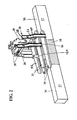
- Figure 2 is an oblique view of the belt drive assembly of the machine illustrated in Figure 1, in its large ware configuration;
- Figure 3 is an oblique view of a guide wheel assembly for one of the opposed belt drives;
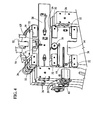
- Figure 4 is an oblique view of the belt drive assembly housing including the open/close step motors;
- Figure 5 is a bottom view of a belt drive unit; and
- Figure 6 is an oblique view of the belt drive assembly illustrated in Figure 2, in its mini ware configuration.
-
- Figure 1 is a schematic showing of an
inspection machine 10 which inspects a row ofbottles 12 conveyed to the machine by an infeedconveyor 14. Any of a variety of inspections can be carried out by the machine. - Figure 2 illustrates the
belt conveyor mechanism 20 for this machine which receives, i.e. picks up, bottles from the infeedconveyor 14, conveys them through one or more inspection locations, and releases them to adischarge conveyor 16. The infeed and discharge conveyors havefront guards 17 which, together with afront guard 18 for the inspection equipment (light sources, cameras, etc.), define the front face of the infeed/discharge conveyor system. - As can be seen, the belt conveyor mechanism has an upper opposed pair of
belt drives 22 and a lower opposed pair ofbelt drives 24. Each of the belt drives 22, 24 is cantilevered from a generally vertical or upwardly extendingstrut 26 which is integral with ahorizontal slide member 28. The two slide members of the upper/lower opposed pair of belt drives each include a rack portion 29 (one shown in Figure 4) which is operatively associated with anidler pinion 30. - The two
slide members 28 of an opposed pair of belt drives are supported for lateral displacement by three pairs of rollers 32 (Figures 3 and 4) which are mounted on a verticallydisplaceable carriage 34. The top slide member is supported between the top and middle roller pair and the bottom slide member (shown in Figure 3 but omitted from Figure 4 from below the lower rack portion 5 to reveal otherwise concealed components) is supported between the middle and bottom roller pairs. Aslide member 28 can enter asuitable hole 31 in an associated opposedstrut 26 when the opposed pair of belt drives is closed towards each other. Thecarriage 34 also supports upper and lower opposed pairs ofrollers 36 which are captured by outer tracks (not shown) on a housing 38 (Figure 4) which is secured to the machine frame to depend over the inspection area, thus mounting the carriage for vertical displacement relative to thehousing 38. - When an open/
close step motor 40 is operated (there is a motor for each opposed pair of belt drives), apulley 42 drives ascrew 44 which is threadedly received by a corresponding nut secured within the lower slide member (not shown in Figure 4) which displaces the lower slide member and the attached strut. This displacement will be mirrored by the associated upper slide member and its opposed belt drive, since the upper and lower rack portions of the slide members are coupled together via theidler pinion 30. Operation of an open/close motor will accordingly conjointly horizontally displace the associated opposed upper or lower belt drives either towards or away from each other. - In addition to, or instead of, providing the
motors 40 andscrews 42 to displace the belt drives towards and/or away from each other, the displacement may be effected or supplemented by driving the associatedpinions 30. - The
housing 38 is integral with amounting 39 which is secured to the machine frame, and mounted on the housing are a pair of up/downmotors 50. One motor is associated with the upper drive belts and the other is associated with the lower drive belts. Eachmotor 50 operates apulley 51 which rotatably drives ascrew 53 which is operatively received by anelongated nut 52 which is joined to thecarriage 34 via abracket 54. - Each belt drive (Fig. 5) has a casing or
arm 55 which supports apulley 56 at either end of the arm. These pulleys support abelt 57 which is driven via atiming belt 58 interconnecting one of these pulleys with astep motor drive 60. Theother pulley 56 is an idler pulley. The step motor is mounted on top of the casing as shown in Fig. 2. The step motor for a lower belt drive is mounted on the top surface of the lower casing so that it can enter a pocket orcutout 62 defined in the upper casing. To facilitate vertical displacement, each assembly is counterbalanced to substantially remove the weight of the assembly. - Figure 2 shows the upper and lower belt drive pairs being located in a
large ware 12A configuration with the upper and lower belt drives being vertically stacked. - Figure 6 illustrates the location of the upper and lower drive belt pairs in a small or
mini ware 12B configuration. To reach this configuration the upper belt drive pair is elevated to separate the vertically adjacent belt drives so that they can be displaced relatively horizontally (the top of the motor on the lower drive is clear of the upper casing). The lower belt drive pair is horizontally separated to the location where both lower belt drives are horizontally cleared of thefront wall outfeed conveyors 14. Finally, the upper drive belt pair is now lowered to a location where the casing is just above the top surface of theconveyor 14. Now the drive belts of the upper drive belt pair can be located adjacent the sidewall ofmini ware 12B.
Claims (2)
- A conveyor system for a machine for inspecting containers, comprising
an infeed conveyor for delivering containers to a pick up location,
a belt drive conveyor mechanism for picking up a container at the pick up location and delivering the picked up container to a release position,
a discharge conveyor for receiving a container delivered to the release position,
said belt drive conveyor mechanism comprising upper and lower opposed pairs of belt drive assemblies each belt drive assembly including
a belt drive casing,
belt supporting means mounted on said belt drive casing, said belt supporting means having a drivable member, and
motor means mounted on said casing for driving said drivable member. - A conveyor system according to claim 1, wherein said motor means is a step motor.
Applications Claiming Priority (2)
| Application Number | Priority Date | Filing Date | Title |
|---|---|---|---|
| US610234 | 2003-06-30 | ||
| US10/610,234 US6915894B2 (en) | 2003-06-30 | 2003-06-30 | Container inspection machine |
Publications (3)
| Publication Number | Publication Date |
|---|---|
| EP1493691A2 true EP1493691A2 (en) | 2005-01-05 |
| EP1493691A3 EP1493691A3 (en) | 2005-12-21 |
| EP1493691B1 EP1493691B1 (en) | 2007-02-28 |
Family
ID=33435394
Family Applications (1)
| Application Number | Title | Priority Date | Filing Date |
|---|---|---|---|
| EP04253465A Expired - Fee Related EP1493691B1 (en) | 2003-06-30 | 2004-06-10 | Belt drive assembly for container inspection machine |
Country Status (4)
| Country | Link |
|---|---|
| US (1) | US6915894B2 (en) |
| EP (1) | EP1493691B1 (en) |
| JP (1) | JP2005022872A (en) |
| DE (1) | DE602004004946T2 (en) |
Families Citing this family (4)
| Publication number | Priority date | Publication date | Assignee | Title |
|---|---|---|---|---|
| US8548771B2 (en) | 2008-05-13 | 2013-10-01 | Emhart Glass S.A. | Out-of-round container detection system and method |
| JP5196174B2 (en) | 2008-09-18 | 2013-05-15 | キリンテクノシステム株式会社 | Suction type table, and container transport device and container inspection device using the same |
| US8274001B2 (en) * | 2009-12-31 | 2012-09-25 | Mettler-Toledo, LLC | Weighing apparatus having opposed wheels |
| US9322787B1 (en) | 2014-10-18 | 2016-04-26 | Emhart Glass S.A. | Glass container inspection machine with a graphic user interface |
Citations (7)
| Publication number | Priority date | Publication date | Assignee | Title |
|---|---|---|---|---|
| US3901381A (en) * | 1973-10-10 | 1975-08-26 | Ball Brothers Service Corp | Automatic ware handler |
| US5422476A (en) * | 1993-09-15 | 1995-06-06 | Emhart Glass Machinery Investments Inc. | Glass container inspection machine |
| US5624021A (en) * | 1994-10-24 | 1997-04-29 | Agr International, Inc. | Speed adjusting apparatus for containers |
| WO1997046329A1 (en) * | 1996-06-04 | 1997-12-11 | Inex, Inc. Doing Business As Inex Vision Systems, Inc. | System and method for stress detection in a molded container |
| US5823317A (en) * | 1996-12-04 | 1998-10-20 | New England Machinery, Inc. | Apparatus for uniformly orientating articles |
| US6109426A (en) * | 1996-11-13 | 2000-08-29 | Simplimatic Engineering Company | Oriented bottle conveyor |
| US6390282B1 (en) * | 2000-06-26 | 2002-05-21 | Ouellette Machinery Systems, Inc. | Horizontal belt conveyor with quick vertical adjustment |
Family Cites Families (7)
| Publication number | Priority date | Publication date | Assignee | Title |
|---|---|---|---|---|
| JPS62176118U (en) * | 1986-04-28 | 1987-11-09 | ||
| US5044876A (en) * | 1990-05-02 | 1991-09-03 | Apv Crepaco, Inc. | Apparatus for forming and transferring groups of articles |
| JPH07215476A (en) * | 1994-02-02 | 1995-08-15 | Rohm Co Ltd | Method and device for carrying frame for manufacturing electronic parts |
| JP2000266589A (en) * | 1999-03-16 | 2000-09-29 | Ishida Co Ltd | Weighing equipment having conveyer |
| JP3393549B2 (en) * | 1999-08-03 | 2003-04-07 | 日清食品株式会社 | Article conveying apparatus and article conveying method |
| DE19949440A1 (en) * | 1999-10-14 | 2001-05-03 | Knapp Logistik Automation | Conveyor track arrangement in a filling station |
| JP4056810B2 (en) * | 2002-07-10 | 2008-03-05 | キリンテクノシステム株式会社 | Container inspection device and container inspection system using this device |
-
2003
- 2003-06-30 US US10/610,234 patent/US6915894B2/en not_active Expired - Lifetime
-
2004
- 2004-06-01 JP JP2004162730A patent/JP2005022872A/en active Pending
- 2004-06-10 EP EP04253465A patent/EP1493691B1/en not_active Expired - Fee Related
- 2004-06-10 DE DE602004004946T patent/DE602004004946T2/en active Active
Patent Citations (7)
| Publication number | Priority date | Publication date | Assignee | Title |
|---|---|---|---|---|
| US3901381A (en) * | 1973-10-10 | 1975-08-26 | Ball Brothers Service Corp | Automatic ware handler |
| US5422476A (en) * | 1993-09-15 | 1995-06-06 | Emhart Glass Machinery Investments Inc. | Glass container inspection machine |
| US5624021A (en) * | 1994-10-24 | 1997-04-29 | Agr International, Inc. | Speed adjusting apparatus for containers |
| WO1997046329A1 (en) * | 1996-06-04 | 1997-12-11 | Inex, Inc. Doing Business As Inex Vision Systems, Inc. | System and method for stress detection in a molded container |
| US6109426A (en) * | 1996-11-13 | 2000-08-29 | Simplimatic Engineering Company | Oriented bottle conveyor |
| US5823317A (en) * | 1996-12-04 | 1998-10-20 | New England Machinery, Inc. | Apparatus for uniformly orientating articles |
| US6390282B1 (en) * | 2000-06-26 | 2002-05-21 | Ouellette Machinery Systems, Inc. | Horizontal belt conveyor with quick vertical adjustment |
Also Published As
| Publication number | Publication date |
|---|---|
| DE602004004946D1 (en) | 2007-04-12 |
| JP2005022872A (en) | 2005-01-27 |
| EP1493691A3 (en) | 2005-12-21 |
| US20040262125A1 (en) | 2004-12-30 |
| US6915894B2 (en) | 2005-07-12 |
| DE602004004946T2 (en) | 2007-07-05 |
| EP1493691B1 (en) | 2007-02-28 |
Similar Documents
| Publication | Publication Date | Title |
|---|---|---|
| CN108389808B (en) | Silicon chip sorting machine | |
| KR101473301B1 (en) | System and method for conveying glasses with function of processing broken glasses | |
| CN104909176A (en) | Automatic fruit box turning, discharging and fruit box recycling production line | |
| US7166021B2 (en) | Method and apparatus for loading and/or unloading a storage unit | |
| EP1493690B1 (en) | Belt drive assembly for container inspection machine | |
| EP1493691B1 (en) | Belt drive assembly for container inspection machine | |
| CN112027658A (en) | Feeding equipment, feeding method and electronic product part detection system | |
| CN214649510U (en) | Chartered plane is examined to high efficiency carousel | |
| CN115565922A (en) | Automatic alternating double-track sorting and feeding machine for silicon wafers | |
| KR100923906B1 (en) | X-ray INSPECTION APPARATUS OF GETTER FOR LIQUID CRYSTAL DISPLAY | |
| CN108564727B (en) | Automatic vending equipment for frozen products | |
| CN218144186U (en) | Turnover type blank discharging machine | |
| CN219649771U (en) | High assembly quality of security | |
| CN106516741A (en) | Conveying system for full-automatic online glass laminating machine | |
| CN100386629C (en) | Inspection apparatus | |
| CN116603754B (en) | High-speed silicon chip sorter | |
| CN117246584B (en) | Automatic packaging system for automobile balance weight | |
| CN116532374B (en) | Full-automatic semiconductor detection equipment | |
| KR20070095308A (en) | Board material storing method and apparatus | |
| CN217664747U (en) | PCB circuit board FCT functional test automation line is with unloading conveying mechanism | |
| CN219979531U (en) | Switching device and photovoltaic cell manufacturing equipment | |
| CN114067490B (en) | Cigarette exhibition stores up all-in-one | |
| CN213914949U (en) | Wire sequence detector for wire harness processing | |
| CN217101635U (en) | Metal rod blanking device | |
| CN220258804U (en) | Automatic monitoring and sorting device for packaging boxes |
Legal Events
| Date | Code | Title | Description |
|---|---|---|---|
| PUAI | Public reference made under article 153(3) epc to a published international application that has entered the european phase |
Free format text: ORIGINAL CODE: 0009012 |
|
| AK | Designated contracting states |
Kind code of ref document: A2 Designated state(s): AT BE BG CH CY CZ DE DK EE ES FI FR GB GR HU IE IT LI LU MC NL PL PT RO SE SI SK TR |
|
| AX | Request for extension of the european patent |
Extension state: AL HR LT LV MK |
|
| PUAL | Search report despatched |
Free format text: ORIGINAL CODE: 0009013 |
|
| AK | Designated contracting states |
Kind code of ref document: A3 Designated state(s): AT BE BG CH CY CZ DE DK EE ES FI FR GB GR HU IE IT LI LU MC NL PL PT RO SE SI SK TR |
|
| AX | Request for extension of the european patent |
Extension state: AL HR LT LV MK |
|
| 17P | Request for examination filed |
Effective date: 20060303 |
|
| AKX | Designation fees paid |
Designated state(s): DE FR GB IT |
|
| GRAP | Despatch of communication of intention to grant a patent |
Free format text: ORIGINAL CODE: EPIDOSNIGR1 |
|
| GRAS | Grant fee paid |
Free format text: ORIGINAL CODE: EPIDOSNIGR3 |
|
| GRAA | (expected) grant |
Free format text: ORIGINAL CODE: 0009210 |
|
| AK | Designated contracting states |
Kind code of ref document: B1 Designated state(s): DE FR GB IT |
|
| REG | Reference to a national code |
Ref country code: GB Ref legal event code: FG4D |
|
| REF | Corresponds to: |
Ref document number: 602004004946 Country of ref document: DE Date of ref document: 20070412 Kind code of ref document: P |
|
| ET | Fr: translation filed | ||
| PLBE | No opposition filed within time limit |
Free format text: ORIGINAL CODE: 0009261 |
|
| STAA | Information on the status of an ep patent application or granted ep patent |
Free format text: STATUS: NO OPPOSITION FILED WITHIN TIME LIMIT |
|
| 26N | No opposition filed |
Effective date: 20071129 |
|
| PGFP | Annual fee paid to national office [announced via postgrant information from national office to epo] |
Ref country code: FR Payment date: 20110629 Year of fee payment: 8 |
|
| PGFP | Annual fee paid to national office [announced via postgrant information from national office to epo] |
Ref country code: GB Payment date: 20110628 Year of fee payment: 8 |
|
| PGFP | Annual fee paid to national office [announced via postgrant information from national office to epo] |
Ref country code: IT Payment date: 20110623 Year of fee payment: 8 |
|
| PGFP | Annual fee paid to national office [announced via postgrant information from national office to epo] |
Ref country code: DE Payment date: 20110629 Year of fee payment: 8 |
|
| GBPC | Gb: european patent ceased through non-payment of renewal fee |
Effective date: 20120610 |
|
| PG25 | Lapsed in a contracting state [announced via postgrant information from national office to epo] |
Ref country code: IT Free format text: LAPSE BECAUSE OF NON-PAYMENT OF DUE FEES Effective date: 20120610 |
|
| REG | Reference to a national code |
Ref country code: FR Ref legal event code: ST Effective date: 20130228 |
|
| REG | Reference to a national code |
Ref country code: DE Ref legal event code: R119 Ref document number: 602004004946 Country of ref document: DE Effective date: 20130101 |
|
| PG25 | Lapsed in a contracting state [announced via postgrant information from national office to epo] |
Ref country code: DE Free format text: LAPSE BECAUSE OF NON-PAYMENT OF DUE FEES Effective date: 20130101 Ref country code: FR Free format text: LAPSE BECAUSE OF NON-PAYMENT OF DUE FEES Effective date: 20120702 Ref country code: GB Free format text: LAPSE BECAUSE OF NON-PAYMENT OF DUE FEES Effective date: 20120610 |