EP1495724A1 - Surgical retractors - Google Patents
Surgical retractors Download PDFInfo
- Publication number
- EP1495724A1 EP1495724A1 EP04015356A EP04015356A EP1495724A1 EP 1495724 A1 EP1495724 A1 EP 1495724A1 EP 04015356 A EP04015356 A EP 04015356A EP 04015356 A EP04015356 A EP 04015356A EP 1495724 A1 EP1495724 A1 EP 1495724A1
- Authority
- EP
- European Patent Office
- Prior art keywords
- arms
- incision
- pair
- arm
- open
- Prior art date
- Legal status (The legal status is an assumption and is not a legal conclusion. Google has not performed a legal analysis and makes no representation as to the accuracy of the status listed.)
- Granted
Links
Images


Classifications
-
- A—HUMAN NECESSITIES
- A61—MEDICAL OR VETERINARY SCIENCE; HYGIENE
- A61B—DIAGNOSIS; SURGERY; IDENTIFICATION
- A61B17/00—Surgical instruments, devices or methods, e.g. tourniquets
- A61B17/02—Surgical instruments, devices or methods, e.g. tourniquets for holding wounds open; Tractors
-
- A—HUMAN NECESSITIES
- A61—MEDICAL OR VETERINARY SCIENCE; HYGIENE
- A61B—DIAGNOSIS; SURGERY; IDENTIFICATION
- A61B17/00—Surgical instruments, devices or methods, e.g. tourniquets
- A61B17/02—Surgical instruments, devices or methods, e.g. tourniquets for holding wounds open; Tractors
- A61B17/0206—Surgical instruments, devices or methods, e.g. tourniquets for holding wounds open; Tractors with antagonistic arms as supports for retractor elements
Definitions
- the present invention relates to surgical retractors for holding open an incision made for example for a surgical operation. More particularly, the present invention pertains to surgical retractors that can prevent a handle portion of the surgical retractors from being raised higher even if a deep portion of the incision needs to be held open by a blade.
- Surgical retractors for ensuring an operative field by spreading and holding open a surgical incision have been disclosed, for example, in Japanese Publication of Registered Utility Model Applications 2,131,233.
- the surgical retractors disclosed in the publication are obtained by devising a so-called nasal speculum and allow the incision to be spread by inserting an extremity portion thereof into the incision and closing grippers.
- the surgical retractors have a drawback in that it is difficult to hold open the incision to a fixed extent because the grippers have to be kept closed by the user during the operation.
- the ecarteur for holding a surgical incision to a fixed extent has been disclosed in Japanese Patent Application Laid-open H09-234,204.
- the ecarteur has a pair of branch portions disposed in parallel with each other, each of the base edge thereof being connected to each other by means of a connecting portion. With this connecting portion, each of extremity portions thereof is capable of moving to and away from each other elastically.
- the ecarteur has a positioning member, disposed between the pair of branch portions, for regulating the position of the pair of branch portions, thereby allowing the distance between the extremity portions thereof to be kept constant during operation.
- the surgical retractors 1 for holding open an incision that has been made, for example, over a patient's spinal cord have been comprised of a pair of arms 5A, 5B that are openably and closably connected with each other by means of a hinge portion 7, the arm 5A(5B) having at its extremity portion a blade 3 for spreading and holding the incision open.
- the arm 5A(5B) is integrally provided with a handle 9A(9B) for performing an open/close operation of the pair of arms 5A, 5B.
- At the end of the handles 9A, 9B are provided respectively rings 11A, 11B for user's fingers to be inserted.
- the arms 5A, 5B pivot around the hinge 7 and the extremity portions of the arms 5A, 5B open accordingly.
- the handles 9A, 9B are provided at a position adjacent to the hinge 7 with a lock mechanism 13 for locking the handles 9A, 9B against each other.
- the lock mechanism 13 is comprised of a plate 15 that is formed into an arc shape around the hinge 7 and secured on one handle 9A, a ratchet finger member 17 that is pivotably provided on the other handle 9B, the end portion of the member 17 being capable of meshing with a ratchet teeth portion 15A formed on the peripheral of the plate 15, and a leaf spring 19 that is provided on the handle 9B in order to deflect the ratchet finger member 17 into engagement with the ratchet teeth portion 15A.
- the present invention which has been made in light of the aforementioned problem, provides surgical retractors provided with a pair of arms which are openable and closable via a hinge portion and include at an extremity portion thereof a blade for spreading and holding open an incision and a pair of handles for performing an open and close operation of said pair of arms, the pair of handles being provided on said pair of arms respectively, wherein there is provided at an extremity side of each of said arms a bent arm portion that bends downward in relation to the arm, and a bend line, formed at an extremity portion of said blade provided at an extremity portion of the bent arm portion, is substantially parallel with said arm when seen from a lateral side.
- the bent arm portion is provided at the end thereof with a blade back portion that extends substantially parallel with the arm when seen from a lateral side, and the blade back portion is provided with the blades.
- blades for holding open a surgical incision when the incision needs to be held open are provided at an end of the bent arms that are formed at an end of the arms so as to bend downward and the bend line is parallel with the arm when seen from a lateral side, even when the blade is inserted deep beneath a skin in the incision, the bend line at the end of the blade can be maintained substantially parallel with the surface of the patient's body. Therefore, the arms and handles are prevented from being raised, thereby solving the aforementioned problem.
- surgical retractors 1A are composed of a pair of arms 5A, 5B which are connected with each other by means of a hinge portion 7 so as to open/close and provided respectively with a blade 3 for spreading and holding an incision open at an end portion of the arms 5A, 5B, and a pair of handles 9A, 9B formed on the arms 5A, 5B for performing an open/close operation of the arms 5A, 5B, as in the case of the aforementioned conventional surgical retractors 1.
- the surgical retractors 1A are provided with bent arms 21A, 21B that bend downward in relation to the arms 5A, 5B at the end of the arms 5A, 5B, respectively, the arms 21A, 21B having at their own ends the blades 3.
- the tip or lower portion of each blade 3 bends away from each other (outward) at a position of the bend line L.
- the bend line L is formed so as to be substantially parallel with the plane P formed by the arm 5A, 5B and the handles 11A, 11A, as shown in Fig.3.
- the bent arms 21A, 21B bend downward at an angle of about 45 degree in relation to the arms 5A, 5B, as shown in Fig.3.
- a blade back portion 3A that can be supported horizontally when supporting the arms 5A, 5B horizontally and extends from the arms 5A, 5B.
- the blade back portion 3A is formed so as to be parallel with the arm 5A, 5B, when the blade back portion 3A and the arms 5A are seen from their lateral side.
- the blade back portion 3A is provided integrally with a plural of finger portions 3B that are formed so as to extend downward and substantially orthogonal with the blade back portion 3A.
- the lower end of the finger portions 3B bends outward at the bent line L.
- Such a configuration allows the following way of using the surgical retractors 1 when performing a surgical operation for a patient's spinal cord, for example (see Fig.4).
- an incision 23 made on his or her back is spread widen, at first, the edge of the incision 23 is spread to a certain extent at a portion of the incision 23 adjacent to the end thereof using smaller sized surgical retractors 1B.
- blades 3 of larger sized surgical retractors 1A are inserted deep into the incision 23 until the extremity portion of the blades 3 reaches beneath the skin. Then, the incision 23 is spread wide to an appropriate extent by closing the handles 9A, 9B and the arms 5A, 5B are locked with each other by the lock mechanism 13.
- the arms 5A, 5B and handle 9A, 9B of the surgical retractors 1A can be overlaid partially on the smaller surgical retractors 1B.
- This can be realized because the bent arms 21A, 21B are bent downward from the arm 5A, 5B and also the bend line L at which the lower portions of the blades 3 are bent outward is substantially parallel with the arms 5A, 5B and handles 9A, 9B, seen from their lateral side.
- the surgical retractors according to the present invention are applicable in spreading and holding a surgical incision open.
Abstract
Description
- The present invention relates to surgical retractors for holding open an incision made for example for a surgical operation. More particularly, the present invention pertains to surgical retractors that can prevent a handle portion of the surgical retractors from being raised higher even if a deep portion of the incision needs to be held open by a blade.
- Surgical retractors for ensuring an operative field by spreading and holding open a surgical incision have been disclosed, for example, in Japanese Publication of Registered Utility Model Applications 2,131,233. The surgical retractors disclosed in the publication are obtained by devising a so-called nasal speculum and allow the incision to be spread by inserting an extremity portion thereof into the incision and closing grippers. However, the surgical retractors have a drawback in that it is difficult to hold open the incision to a fixed extent because the grippers have to be kept closed by the user during the operation.
- An ecarteur for holding a surgical incision to a fixed extent has been disclosed in Japanese Patent Application Laid-open H09-234,204. The ecarteur has a pair of branch portions disposed in parallel with each other, each of the base edge thereof being connected to each other by means of a connecting portion. With this connecting portion, each of extremity portions thereof is capable of moving to and away from each other elastically. In addition, the ecarteur has a positioning member, disposed between the pair of branch portions, for regulating the position of the pair of branch portions, thereby allowing the distance between the extremity portions thereof to be kept constant during operation.
- Another example of conventional surgical retractors has been described in "MIZUHO" ORTHOPEDIC IMPLANTS & INSTRUMENTS (MIZUHO Co., Ltd., December 2002). As shown in Fig.1, the surgical retractors 1 for holding open an incision that has been made, for example, over a patient's spinal cord have been comprised of a pair of
arms hinge portion 7, thearm 5A(5B) having at its extremity portion ablade 3 for spreading and holding the incision open. Also, thearm 5A(5B) is integrally provided with ahandle 9A(9B) for performing an open/close operation of the pair ofarms handles - When a user inserts his or her fingers into the
rings handles arms hinge 7 and the extremity portions of thearms handles hinge 7 with alock mechanism 13 for locking thehandles - The
lock mechanism 13 is comprised of aplate 15 that is formed into an arc shape around thehinge 7 and secured on onehandle 9A, aratchet finger member 17 that is pivotably provided on theother handle 9B, the end portion of themember 17 being capable of meshing with aratchet teeth portion 15A formed on the peripheral of theplate 15, and aleaf spring 19 that is provided on thehandle 9B in order to deflect theratchet finger member 17 into engagement with theratchet teeth portion 15A. - In case of the conventional surgical retractors 1 having such a configuration, when the
blades 3 are inserted deep into an incision made on a patient body in an attempt to spread and hold open a deep portion of the incision, thearms handles rings blades 3 are inserted into the incision, the steeper the inclination of thearms handles rings - So, there must be a problem in that the
arms handles rings - The present invention, which has been made in light of the aforementioned problem, provides surgical retractors provided with a pair of arms which are openable and closable via a hinge portion and include at an extremity portion thereof a blade for spreading and holding open an incision and a pair of handles for performing an open and close operation of said pair of arms, the pair of handles being provided on said pair of arms respectively, wherein there is provided at an extremity side of each of said arms a bent arm portion that bends downward in relation to the arm, and a bend line, formed at an extremity portion of said blade provided at an extremity portion of the bent arm portion, is substantially parallel with said arm when seen from a lateral side.
- Also, the bent arm portion is provided at the end thereof with a blade back portion that extends substantially parallel with the arm when seen from a lateral side, and the blade back portion is provided with the blades.
- According to the present invention, since blades for holding open a surgical incision when the incision needs to be held open are provided at an end of the bent arms that are formed at an end of the arms so as to bend downward and the bend line is parallel with the arm when seen from a lateral side, even when the blade is inserted deep beneath a skin in the incision, the bend line at the end of the blade can be maintained substantially parallel with the surface of the patient's body. Therefore, the arms and handles are prevented from being raised, thereby solving the aforementioned problem.
- In the accompanying drawings:
- Fig.1 is an illustration of conventional surgical retractors;
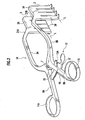
- Fig.2 is a perspective illustration of surgical retractors according to the present invention;
- Fig.3 is a lateral illustration of surgical retractors according to the present invention; and,
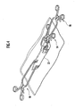
- Fig.4 is an illustration of surgical retractors according to the present invention in use for a surgical incision.
-
- Surgical retractors according to an embodiment of the present invention will be explained in detail hereinafter with reference to the accompanying drawings. In the drawings, an identical reference numeral is used to specify an identical element that demonstrates the same function as the aforementioned conventional one does, in order to avoid undue repetition in explanation.
- Referring to Figs. 2 and 3,
surgical retractors 1A according to an embodiment of the present invention are composed of a pair ofarms hinge portion 7 so as to open/close and provided respectively with ablade 3 for spreading and holding an incision open at an end portion of thearms handles arms arms - Also, the
surgical retractors 1A are provided withbent arms arms arms arms blades 3. The tip or lower portion of eachblade 3 bends away from each other (outward) at a position of the bend line L. Seen from a lateral side, the bend line L is formed so as to be substantially parallel with the plane P formed by thearm handles - More particularly, the
bent arms arms bent arms blade back portion 3A that can be supported horizontally when supporting thearms arms portion 3A is formed so as to be parallel with thearm portion 3A and thearms 5A are seen from their lateral side. - Moreover, the blade back
portion 3A is provided integrally with a plural offinger portions 3B that are formed so as to extend downward and substantially orthogonal with theblade back portion 3A. The lower end of thefinger portions 3B bends outward at the bent line L. - Such a configuration allows the following way of using the surgical retractors 1 when performing a surgical operation for a patient's spinal cord, for example (see Fig.4). When an
incision 23 made on his or her back is spread widen, at first, the edge of theincision 23 is spread to a certain extent at a portion of theincision 23 adjacent to the end thereof using smaller sizedsurgical retractors 1B. Next, at the center portion of theincision 23,blades 3 of larger sizedsurgical retractors 1A are inserted deep into theincision 23 until the extremity portion of theblades 3 reaches beneath the skin. Then, theincision 23 is spread wide to an appropriate extent by closing thehandles arms lock mechanism 13. In this situation, thearms surgical retractors 1A can be overlaid partially on the smallersurgical retractors 1B. This can be realized because thebent arms arm blades 3 are bent outward is substantially parallel with thearms - In other words, even when a deep portion of the incision needs to be spread wide by inserting the
blades 3 deep beneath the skin at the center portion of theincision 23, thearms handles rings arms handles rings - The surgical retractors according to the present invention are applicable in spreading and holding a surgical incision open.
- Additional advantages and modifications will readily occur to those skilled in the art. Therefore, the invention in its broader aspects is not limited to the specific details and representative embodiments shown and described herein. Accordingly, various modifications may be made without departing from the spirit or scope of the general inventive concept as defined by the appended claims and their equivalents.
Claims (1)
- Surgical retractors (1A) provided with a pair of arms (5A, 5B) which are openable and closable via a hinge portion (7) and include at an extremity portion thereof a blade (3) for spreading and holding open an incision and a pair of handles (9A, 9B) for performing an open/close operation of said pair of arms (5A, 5B), the pair of handles (9A, 9B) being provided on said pair of arms (5A, 5B) respectively, wherein there is provided at an extremity side of each of said arms (5A, 5B) a bent arm portion (21A, 21B) that bends downward in relation to the arm, and a bend line (L), formed at an extremity portion of said blade (3) provided at an extremity end of the bent arm portion (21A, 21B), is substantially parallel with said arm (5A, 5B) when seen from a lateral side.
Applications Claiming Priority (2)
| Application Number | Priority Date | Filing Date | Title |
|---|---|---|---|
| JP2003272999A JP2005028001A (en) | 2003-07-10 | 2003-07-10 | Retractor |
| JP2003272999 | 2003-07-10 |
Publications (2)
| Publication Number | Publication Date |
|---|---|
| EP1495724A1 true EP1495724A1 (en) | 2005-01-12 |
| EP1495724B1 EP1495724B1 (en) | 2008-11-05 |
Family
ID=33448061
Family Applications (1)
| Application Number | Title | Priority Date | Filing Date |
|---|---|---|---|
| EP04015356A Expired - Fee Related EP1495724B1 (en) | 2003-07-10 | 2004-06-30 | Surgical retractors |
Country Status (5)
| Country | Link |
|---|---|
| US (1) | US20050027170A1 (en) |
| EP (1) | EP1495724B1 (en) |
| JP (1) | JP2005028001A (en) |
| KR (1) | KR100621478B1 (en) |
| DE (1) | DE602004017544D1 (en) |
Cited By (5)
| Publication number | Priority date | Publication date | Assignee | Title |
|---|---|---|---|---|
| GB2424373A (en) * | 2005-03-11 | 2006-09-27 | Winter & Ibe Olympus | Medical instrument with an actuating handle having a ratchet lock |
| WO2015019189A3 (en) * | 2013-08-06 | 2015-08-06 | Microport Orthopedics Holdings Inc. | Methods and tools for hip replacement with supercapsular percutaneously assisted total hip approach |
| CN106859709A (en) * | 2016-12-28 | 2017-06-20 | 四川大学华西医院 | A kind of cervical vertebra drag hook |
| CN108186062A (en) * | 2018-02-10 | 2018-06-22 | 刘陈邦 | A kind of medical treatment retractor |
| WO2022107120A1 (en) * | 2020-11-17 | 2022-05-27 | Mazor Robotics Ltd. | Automated robotic retractor |
Families Citing this family (16)
| Publication number | Priority date | Publication date | Assignee | Title |
|---|---|---|---|---|
| US20070299315A1 (en) * | 2006-06-21 | 2007-12-27 | Geller Peter L | Novel retractor for hernia surgery |
| JP4897458B2 (en) * | 2006-12-11 | 2012-03-14 | 有限会社エスアールジェイ | Medical balloon wearing jig |
| US8211012B2 (en) * | 2008-09-30 | 2012-07-03 | Aesculap Implant Systems, Llc | Tissue retractor system |
| US9750545B2 (en) * | 2009-03-27 | 2017-09-05 | Globus Medical, Inc. | Devices and methods for inserting a vertebral fixation member |
| KR101070049B1 (en) | 2009-05-06 | 2011-10-04 | 국립암센터 | Surgical instrument |
| CN102647947A (en) * | 2009-10-23 | 2012-08-22 | 碧维-韦斯泰科国际(美国)股份有限公司 | Speculum |
| CN101797169B (en) * | 2010-03-25 | 2012-01-11 | 广东省第二人民医院 | Tissue pulling and vessel exposing device |
| CN102715927A (en) * | 2012-07-07 | 2012-10-10 | 苏州市康力骨科器械有限公司 | Minimal invasive opening forceps |
| TWI618551B (en) * | 2016-03-28 | 2018-03-21 | 英濟股份有限公司 | Expander |
| US11583660B2 (en) * | 2016-10-12 | 2023-02-21 | Susan Smith | Female urethral catheterization assist device |
| US20180103941A1 (en) * | 2016-10-13 | 2018-04-19 | Agha Khan | Surgical retractor |
| US10820896B2 (en) * | 2017-06-12 | 2020-11-03 | Globus Medical Inc. | Surgical retractor |
| USD884169S1 (en) * | 2018-01-18 | 2020-05-12 | Paragon 28, Inc. | Clamp |
| US10299670B1 (en) * | 2018-09-06 | 2019-05-28 | King Saud University | Self-retaining nasal septum retractor |
| US20200077997A1 (en) * | 2018-09-10 | 2020-03-12 | Eric McCormick | Radiolucent retractor |
| GB2584084A (en) * | 2019-05-17 | 2020-11-25 | Cambridge Univ Hospitals Nhs Foundation Trust | Tissue splayer |
Citations (8)
| Publication number | Priority date | Publication date | Assignee | Title |
|---|---|---|---|---|
| GB920691A (en) * | 1962-01-02 | 1963-03-13 | Sklar Mfg Company J | Surgical instrument |
| JPH02131233U (en) | 1989-04-06 | 1990-10-31 | ||
| US5363841A (en) * | 1993-07-02 | 1994-11-15 | Coker Wesley L | Retractor for spinal surgery |
| JPH09234204A (en) | 1996-03-01 | 1997-09-09 | Senko Ika Kogyo Kk | Ecarteur |
| US5908382A (en) * | 1998-07-08 | 1999-06-01 | Koros; Tibor B. | Minimally invasive retractor for internal mammary artery harvesting |
| US6042540A (en) * | 1997-08-18 | 2000-03-28 | Pacific Surgical Innovations, Inc. | Side-loading surgical retractor |
| US6302842B1 (en) * | 2001-01-11 | 2001-10-16 | Innovative Surgical Design Llc | Episiotomy retractor |
| US6468207B1 (en) * | 2000-02-04 | 2002-10-22 | Lone Star Medical Products, Inc. | Deep tissue surgical retractor apparatus and method of retracting tissue |
Family Cites Families (4)
| Publication number | Priority date | Publication date | Assignee | Title |
|---|---|---|---|---|
| US3038467A (en) * | 1960-08-29 | 1962-06-12 | Sklar Mfg Co J | Surgical instrument |
| US4034746A (en) * | 1975-08-01 | 1977-07-12 | Williams Robert W | Retractor |
| US4747394A (en) * | 1986-10-08 | 1988-05-31 | Watanabe Orthopedic Systems, Inc. | Spinal retractor |
| US5931777A (en) * | 1998-03-11 | 1999-08-03 | Sava; Gerard A. | Tissue retractor and method for use |
-
2003
- 2003-07-10 JP JP2003272999A patent/JP2005028001A/en active Pending
-
2004
- 2004-06-29 US US10/878,045 patent/US20050027170A1/en not_active Abandoned
- 2004-06-30 EP EP04015356A patent/EP1495724B1/en not_active Expired - Fee Related
- 2004-06-30 DE DE602004017544T patent/DE602004017544D1/en active Active
- 2004-07-07 KR KR1020040052641A patent/KR100621478B1/en not_active IP Right Cessation
Patent Citations (8)
| Publication number | Priority date | Publication date | Assignee | Title |
|---|---|---|---|---|
| GB920691A (en) * | 1962-01-02 | 1963-03-13 | Sklar Mfg Company J | Surgical instrument |
| JPH02131233U (en) | 1989-04-06 | 1990-10-31 | ||
| US5363841A (en) * | 1993-07-02 | 1994-11-15 | Coker Wesley L | Retractor for spinal surgery |
| JPH09234204A (en) | 1996-03-01 | 1997-09-09 | Senko Ika Kogyo Kk | Ecarteur |
| US6042540A (en) * | 1997-08-18 | 2000-03-28 | Pacific Surgical Innovations, Inc. | Side-loading surgical retractor |
| US5908382A (en) * | 1998-07-08 | 1999-06-01 | Koros; Tibor B. | Minimally invasive retractor for internal mammary artery harvesting |
| US6468207B1 (en) * | 2000-02-04 | 2002-10-22 | Lone Star Medical Products, Inc. | Deep tissue surgical retractor apparatus and method of retracting tissue |
| US6302842B1 (en) * | 2001-01-11 | 2001-10-16 | Innovative Surgical Design Llc | Episiotomy retractor |
Cited By (8)
| Publication number | Priority date | Publication date | Assignee | Title |
|---|---|---|---|---|
| GB2424373A (en) * | 2005-03-11 | 2006-09-27 | Winter & Ibe Olympus | Medical instrument with an actuating handle having a ratchet lock |
| GB2424373B (en) * | 2005-03-11 | 2009-09-02 | Winter & Ibe Olympus | Medical instrument with actuating handle |
| WO2015019189A3 (en) * | 2013-08-06 | 2015-08-06 | Microport Orthopedics Holdings Inc. | Methods and tools for hip replacement with supercapsular percutaneously assisted total hip approach |
| CN106859709A (en) * | 2016-12-28 | 2017-06-20 | 四川大学华西医院 | A kind of cervical vertebra drag hook |
| CN106859709B (en) * | 2016-12-28 | 2019-04-23 | 四川大学华西医院 | A kind of cervical vertebra drag hook |
| CN108186062A (en) * | 2018-02-10 | 2018-06-22 | 刘陈邦 | A kind of medical treatment retractor |
| CN108186062B (en) * | 2018-02-10 | 2019-06-07 | 丁汉君 | A kind of medical treatment retractor |
| WO2022107120A1 (en) * | 2020-11-17 | 2022-05-27 | Mazor Robotics Ltd. | Automated robotic retractor |
Also Published As
| Publication number | Publication date |
|---|---|
| JP2005028001A (en) | 2005-02-03 |
| KR20050007147A (en) | 2005-01-17 |
| KR100621478B1 (en) | 2006-09-19 |
| DE602004017544D1 (en) | 2008-12-18 |
| US20050027170A1 (en) | 2005-02-03 |
| EP1495724B1 (en) | 2008-11-05 |
Similar Documents
| Publication | Publication Date | Title |
|---|---|---|
| EP1495724A1 (en) | Surgical retractors | |
| EP2523608B1 (en) | Surgical retractor with curved blades | |
| US4034746A (en) | Retractor | |
| EP1722707B1 (en) | A two-part orthodontic bracket | |
| JP4729523B2 (en) | Thin self-ligating orthodontic bracket and method of using such an orthodontic bracket | |
| US8491593B2 (en) | Targeting device for orthopedic implants | |
| US4321916A (en) | Eyelid retractor | |
| CN106456202A (en) | Surgical grasper | |
| EP1006887A1 (en) | Rib retractor | |
| US10420542B2 (en) | Surgical rib retractor | |
| US10603025B2 (en) | Surgical rib retractor | |
| EP2699173B1 (en) | Surgical needle holder | |
| US20060079931A1 (en) | Surgical deep needle driver | |
| KR101101184B1 (en) | Surgical retractor for single use | |
| US8529580B1 (en) | Surgical grasping instrument with U-shaped jaws in combination with a tympanostomy tube | |
| JP2007044266A (en) | Wound retractor | |
| JP3184163U (en) | Retractor | |
| EP4230180A1 (en) | Eyelid opening device | |
| US20210228197A1 (en) | Surgical rib retractor | |
| US11517298B2 (en) | Surgical rib retractor | |
| US20080160478A1 (en) | Dental retractor | |
| CN219000409U (en) | Needle holder | |
| WO2022185798A1 (en) | Endoscope | |
| CN219089487U (en) | Ligature clamp | |
| CN213850859U (en) | Surgical instrument for lumbar vertebra channel |
Legal Events
| Date | Code | Title | Description |
|---|---|---|---|
| PUAI | Public reference made under article 153(3) epc to a published international application that has entered the european phase |
Free format text: ORIGINAL CODE: 0009012 |
|
| 17P | Request for examination filed |
Effective date: 20040630 |
|
| AK | Designated contracting states |
Kind code of ref document: A1 Designated state(s): AT BE BG CH CY CZ DE DK EE ES FI FR GB GR HU IE IT LI LU MC NL PL PT RO SE SI SK TR |
|
| AX | Request for extension of the european patent |
Extension state: AL HR LT LV MK |
|
| 17Q | First examination report despatched |
Effective date: 20050601 |
|
| AKX | Designation fees paid |
Designated state(s): DE FR |
|
| 17Q | First examination report despatched |
Effective date: 20050601 |
|
| GRAP | Despatch of communication of intention to grant a patent |
Free format text: ORIGINAL CODE: EPIDOSNIGR1 |
|
| GRAS | Grant fee paid |
Free format text: ORIGINAL CODE: EPIDOSNIGR3 |
|
| GRAA | (expected) grant |
Free format text: ORIGINAL CODE: 0009210 |
|
| AK | Designated contracting states |
Kind code of ref document: B1 Designated state(s): DE FR |
|
| REF | Corresponds to: |
Ref document number: 602004017544 Country of ref document: DE Date of ref document: 20081218 Kind code of ref document: P |
|
| PLBE | No opposition filed within time limit |
Free format text: ORIGINAL CODE: 0009261 |
|
| STAA | Information on the status of an ep patent application or granted ep patent |
Free format text: STATUS: NO OPPOSITION FILED WITHIN TIME LIMIT |
|
| 26N | No opposition filed |
Effective date: 20090806 |
|
| PGFP | Annual fee paid to national office [announced via postgrant information from national office to epo] |
Ref country code: FR Payment date: 20100630 Year of fee payment: 7 |
|
| PGFP | Annual fee paid to national office [announced via postgrant information from national office to epo] |
Ref country code: DE Payment date: 20100728 Year of fee payment: 7 |
|
| REG | Reference to a national code |
Ref country code: FR Ref legal event code: ST Effective date: 20120229 |
|
| REG | Reference to a national code |
Ref country code: DE Ref legal event code: R119 Ref document number: 602004017544 Country of ref document: DE Effective date: 20120103 |
|
| PG25 | Lapsed in a contracting state [announced via postgrant information from national office to epo] |
Ref country code: DE Free format text: LAPSE BECAUSE OF NON-PAYMENT OF DUE FEES Effective date: 20120103 Ref country code: FR Free format text: LAPSE BECAUSE OF NON-PAYMENT OF DUE FEES Effective date: 20110630 |