EP1496466A2 - Face shape recognition from stereo images - Google Patents
Face shape recognition from stereo images Download PDFInfo
- Publication number
- EP1496466A2 EP1496466A2 EP04102238A EP04102238A EP1496466A2 EP 1496466 A2 EP1496466 A2 EP 1496466A2 EP 04102238 A EP04102238 A EP 04102238A EP 04102238 A EP04102238 A EP 04102238A EP 1496466 A2 EP1496466 A2 EP 1496466A2
- Authority
- EP
- European Patent Office
- Prior art keywords
- face
- model
- facial features
- models
- points
- Prior art date
- Legal status (The legal status is an assumption and is not a legal conclusion. Google has not performed a legal analysis and makes no representation as to the accuracy of the status listed.)
- Granted
Links
Images


Classifications
-
- G—PHYSICS
- G06—COMPUTING; CALCULATING OR COUNTING
- G06V—IMAGE OR VIDEO RECOGNITION OR UNDERSTANDING
- G06V40/00—Recognition of biometric, human-related or animal-related patterns in image or video data
- G06V40/10—Human or animal bodies, e.g. vehicle occupants or pedestrians; Body parts, e.g. hands
- G06V40/16—Human faces, e.g. facial parts, sketches or expressions
- G06V40/168—Feature extraction; Face representation
- G06V40/171—Local features and components; Facial parts ; Occluding parts, e.g. glasses; Geometrical relationships
-
- G—PHYSICS
- G06—COMPUTING; CALCULATING OR COUNTING
- G06V—IMAGE OR VIDEO RECOGNITION OR UNDERSTANDING
- G06V10/00—Arrangements for image or video recognition or understanding
- G06V10/20—Image preprocessing
-
- G—PHYSICS
- G06—COMPUTING; CALCULATING OR COUNTING
- G06V—IMAGE OR VIDEO RECOGNITION OR UNDERSTANDING
- G06V10/00—Arrangements for image or video recognition or understanding
- G06V10/40—Extraction of image or video features
-
- G—PHYSICS
- G06—COMPUTING; CALCULATING OR COUNTING
- G06V—IMAGE OR VIDEO RECOGNITION OR UNDERSTANDING
- G06V10/00—Arrangements for image or video recognition or understanding
- G06V10/70—Arrangements for image or video recognition or understanding using pattern recognition or machine learning
- G06V10/74—Image or video pattern matching; Proximity measures in feature spaces
- G06V10/75—Organisation of the matching processes, e.g. simultaneous or sequential comparisons of image or video features; Coarse-fine approaches, e.g. multi-scale approaches; using context analysis; Selection of dictionaries
- G06V10/755—Deformable models or variational models, e.g. snakes or active contours
- G06V10/7553—Deformable models or variational models, e.g. snakes or active contours based on shape, e.g. active shape models [ASM]
Definitions
- This invention is directed towards face recognition and more particularly relates to recognizing facial features by locating points on the facial features using multiple images of a face.
- a three dimensional object can be represented in two dimensions.
- representing a three-dimensional object by using two-dimensional views has advantages in object modeling and synthesis.
- the three-dimensional features of the object need not be explicitly recovered and this avoids difficulties in three-dimension based methods. Rather, it is conventional to use view-based models to represent the object with multiple two-dimensional view projections.
- a pixel-wise correspondence map is usually required between each of the two-dimensional views.
- a sparse correspondence map between a small set of feature points, or edges of features, on the object can be used between each of the two-dimensional views.
- the correspondence map can be computed and applied to separate the shape of the object from the texture of the object. As such, both the shape of the object and the texture of the object, from a particular viewpoint, can be modeled in a linear subspace.
- a feature point based correspondence between multiple two-dimensional views is advantageous in some applications because it is more robust in dealing with light intensity and color variations, and can involve less computation than establishing a dense representation of the object. Accordingly, to accurately model an image class of an object, two problems can be addressed and solved.
- the first problem is that of locating feature points on features of the object by using a training set of two-dimensional views. Once the feature points of the features on the object are located, the second problem is that of establishing the underlying correspondence between two or more sets of feature points from a corresponding number of two-dimensional views.
- ASM Active Shape Model
- ASM uses the Principle Component Analysis technique (PCA) to model an object by both the two-dimensional shape variations of the object and the local grey level structures of the object.
- PCA Principle Component Analysis technique
- ASM is a process that includes interrogating two-dimensional images of the object and approximating the shape of features on the object using points (feature points) that respectively represent each feature on the object.
- the features on the object for each view can be matched to a model of the object by using ASM.
- ASM ASM-based model matching
- the detected feature points for each feature on the object may not be geometrically consistent across the different views. This inconsistency occurs because ASM only considers a single view rather than the correspondence between the different views.
- the matching of the model to each of the different views could benefit from the use of a multi-view geometry. While this can be accomplished, it requires that all key feature points of each feature on the object remain visible in each of the two-dimensional views.
- One technique for using ASM involves using a set of training examples of one face view from different viewpoints. From these views of the one face, a set of feature points of facial features on the face can be manually labeled. This manual labeling represents a deformation of the face into its different facial features and respective points that make up the facial features. For instance, these features can include the nose, eyes and mouth. The feature points are those points that mark the facial features on the face.
- ASM uses the set of training data representing the deformation of the face to analyze facial features on a different face by using views of the different face. This conventional ASM technique, however, suffers from inaccuracy in locating facial features in the views of the face being analyzed.
- the conventional ASM technique can only deform the face being analyzed in the ways that the face in the set of training data had been deformed.
- One partial solution to overcome the inherent inaccuracy is to use a larger training database. Such a solution is only partial because it does not take into consideration the local grey-level model fitting for the different views of the face. Local grey-level model fitting tends to interpret the data so as to move facial features toward the strongest photometric edge, which may not necessarily be the actual edge of a facial feature - thus introducing further inaccuracy.
- using a larger training database may further decrease accuracy because the additional data tends to further extend the acceptable facial feature shapes into an inaccurate range for the face being analyzed.
- ASM is not consistent in finding the same facial features in two slightly different views of the same face.
- ASM does not always guarantee that the features identified in training data for a training object will yield similar features when searching two slightly different views of another object. This inability can be attributed to illumination changes in the object as a result of rotating the object in different two-dimensional views, or it can be attributed to different initial parameters.
- Two negative results can occurs when using conventional ASM in this environment.
- One result is that the conventional ASM model will wrongly identify features on an object or will inaccuracy locate the feature points for features on the object. Either way, different two-dimensional views of the same object, when using conventional ASM, will yield features that do not match up between the different two-dimensional views. In consequence, the correspondence between the identified features of the different views is inaccurate when using conventional ASM.
- An implementation of the invention identifies facial features by locating points for the facial features, such as eye comers and nose tip.
- a training set of multiple two-dimensional views of a face are used to develop a set of training data.
- the set of training data is used with two different two-dimensional views of a face in a mathematical model.
- the mathematical model is used to identify both inner and outer facial features on the two different two-dimensional views, thus presenting a stereo-coupling mechanism for identifying facial features on each of the two different views of the face.
- the mathematical model uses epipolar geometry as encoded within a fundamental matrix to constraint the regions on each of the two different views at which facial features will be located.
- the mathematical model finds a geometric correspondence between the points for each facial feature, respectively, on each of the two different views of the same face.
- outer and inner facial features of a face model are matched with that of a first model for a first face image and with that of a second model for a second face image.
- Each of the matching outer and inner facial features of the first and second models is adjusted using the corresponding epipolar constraint for the first and second models.
- the first and second face images are images the same face captured at the substantially the same respective camera orientation. In other implementations, the images have a face pose range differing by the yaw.
- an initialization is performed by using a face model for first and second models for respective first and second face images.
- Each of the first and second models has outer and inner facial features defined by a plurality points.
- a fundamental matrix is estimated for the first and second models.
- the points are updated for each of the inner facial features of the first and second models by using the respective local texture for each point.
- Each of the inner facial features of the first and second models is then updated.
- the points for each of the inner facial features of the first and second models are updated using the fundamental matrix and the corresponding epipolar constraint.
- An update is then performed for each of the outer facial features of the first and second models.
- a representation is output of the inner and outer facial features of the first model. If the second model has converged within a predetermined tolerance of the face model, a representation of the inner and outer facial features of the second model is output.
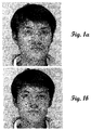
- Figs. 1a-1b illustrates a mechanism for matching comers of different facial features by points that form an outline around each facial feature on two different two-dimensional views of the same face, where the face is in two (2) different positions, and where the mechanism uses a fundamental matrix estimation.
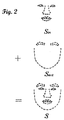
- Fig. 2 illustrates a decomposition of a face into inner and outer facial features, each being outlined by a line connecting a plurality of points.
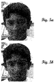
- Figs. 3a-3b show respective two-dimensional views of a face in different poses, where the views represent starting images that can be used by implementations of the invention.
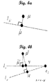
- Figs. 4a-4a are epipolar geometric illustrations depicting the correspondence between points on two different two-dimensional views of an image in accordance with an implementation of the invention.
- Figs. 5a-5b represents, in accordance with an implementation of the invention, a first iteration of a stereo-coupling mechanism for identifying the corresponding facial features on the two different views of Figs. 3a-3b, respectively, by using epipolar geometry as encoded within a fundamental matrix.
- Figs. 6a-6b, 7a-7b, and 8a-8b represent respective iterations of the stereo-coupling mechanism as was used with respect to Figures 5a-5b.
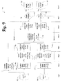
- Fig. 9 is a flow diagram, in accordance with an implementation of the invention, of a procedure for facial feature detection that uses a stereo-coupling mechanism, where the procedure can be used on images seen in Figs. 3a-3b to accomplish the respective iteration results seen in Figs. 5a-5b through 8a-8b.
- Fig. 10 is a block diagram, in accordance with an implementation, of a networked computer that can be used to implement either a server or a client.
- the present invention is directed towards face modeling and identification of facial features.
- Implementations of the present invention use epipolar geometry in face shape analysis to determine facial features, such as the nose, eyes, eye brows, mouth, etc. This detailed description presumes that the reader has an understanding of epipolar geometry.
- Figs. 1a-1b show two target images that are calibrated by an estimate of the fundamental matrix E between them.
- a formula for computing the fundamental matrix E for a pair of images is given by Zhang et al. (Z. Zhang, Determining the epipolar geometry and its uncertainty: a review. The International Journal of Computer Vision, 27(2):161-195, 1998).
- the two images are taken by a static camera while the head is in a frontal position and moving in the yaw direction between the two views. Because the illumination changes when the head is rotating, the color of the same physical point in the two images appears to be different.
- it is advantageous to identify facial features of the face because the identification of facial features is more robust to intensity variations than optical flow based methods.
- the estimation of the fundamental matrix E can include four (4) different steps: 1) approximate the localization of faces by determining differences between the two different images; 2) detect the corners of each facial feature in the images; 3) match the comers of each facial feature by a correlation between the two different images; and 4) reject the false matches and estimate the fundamental matrix by least median squares.
- Figs. 1a-1b shows a pair of face images and the set of comer matches for facial features that are established with this technique. Nevertheless, a face model is needed for more accurate correlation of facial features between the two different images.
- a face model as shown in Fig. 2 and discussed below, is a representation of facial features, e.g., nose, eyes, eye brows, mouth, etc.
- a training set of face shapes, T ⁇ S i
- S i a shape vector, represents the points that make up different features on a face (feature points).
- a face has been decomposed into inner facial features (eyes, nose, and mouth), each of which is seen outlined by a line connecting a plurality of points.
- Fig. 2 shows 63 points that make up these three different inner facial features.
- the face has also been decomposed into outer facial features (a pair of eyebrows and a silhouette of the jaw, chin, and cheeks), each of which is seen outlined by a line connecting a plurality of points.
- Fig. 2 shows 19 points that make up these two different outer facial features. As such, a total of 83 points make up five (5) different facial features as seen in the composite of the decomposed facial features at the bottom of Fig. 2.
- the points on the silhouette are helpful since they can help segment the region of the face from its background. Due to the self occlusion introduced by head rotation in the yaw direction, however, the points on the silhouette are difficult to accurately associate to two different views of the same face in that these points will not comply with the epipolar constraint.
- the decomposed face model is used. As showed in Fig.2, the shape vector S i is divided into two parts, the inner vector S in and the outer vector S out . S in denotes the 64 points that make up the three inside facial features and outer vector S out denotes the other 19 points that define the eye brows and the silhouette or face contour. Of course, a different number of points could be selected to represent each of the facial features.
- PCA Principle Component Analysis technique
- PCA is used again to model the variation of the vectors d and ij .
- One example of the PCA of ASM, as used herein, is given in Cootes et al., discussed above.
- a stereo-coupled model of matching corresponding facial features of two views of the same face starts with an initial guess of the face position and the mean shape vector in both images.
- ASM is applied to each of the two views to update each point of each facial feature according to local texture statistics (e.g., photometric data proximal each point). To do so, the points are moved along a direction that is perpendicular to the model boundary. The quality of the fit is then evaluated, and from this, a new position for each point can be proposed. The best match is often found on a strong edge based upon the magnitude of the photometric data.
- the next step involves finding the most plausible shape which satisfies both the prior shape distribution and the epipolar constraint.
- d ( x,y ) is the Euclidean distance between points x and y
- S in 1 and S in 2 are observed feature points after local texture based updating
- S and in1 and S and in2 denote the model instances:
- the parameters b in1 , and b in2 should satisfy the second conditions to generate a desirably accurate face shape.
- L ( c ) is used to evaluate the difference between model instances and observed feature points.
- L ( c ) can also be viewed as a measure to find the correct corresponding points.
- a typical observed matching ⁇ ' among the shapes S in1 , S in2 can be noisy and there it is desirable to recover the correct one.
- L ( c ) denotes the distance between original feature points ⁇ , ⁇ ' and correct corresponding points , where are the points in the shape instances , .An assumption is made that there will be a Gaussian error distribution of ⁇ , ⁇ ' on the points , which will in turn minimize the loss function L ( c ) for the most likely values that will represent an accurate correspondence between points on the two different views.
- a procedure for locating an accurate correspondence between points on the two different views involves the decomposition of a shape model and the combined constraints of both epipolar constraint ( e.q.3 ) and prior shape constraint ( e.q.4 ).
- such a procedure begins by initializing shape models on two different views of the same face in terms of face detection results.
- An example of the initialization of shape models on two different views that can be used herein is given in Li et al. (S.Z. Li, Q.D. Fu, L. Gu, B. Scholkopf, Y.M. Cheng, H.J. Zhang. "Kernel Machine Based Learning for Multi-View Face Detection and Pose Estimation". In Proceedings of 8th IEEE International Conference on Computer Vision. Vancouver, Canada.
- the points for each facial feature are updated independently using the texture (e.g., photometric data) proximal to each point.
- the inner shape image is updated.
- an initial estimate is given for the inner shape vectors S in 1 , S in 2 .
- This initial estimate is fitted to the image data for the two different views of the face.
- An optimization is sought for parameters of T in 1 , T in 2 , b in 1 , b in 2 and a truncation of b in 1 , b in 2 is made within ⁇ 3 ⁇ k , according to the prior shape constraint.
- an update is made to the points for the inner facial features (nose, eyes, and mouth) according to the epipolar constraint.
- a nonlinear optimization solution is introduced to find the correct correspondence of ⁇ and ⁇ ⁇ and' from the matching of ⁇ ⁇ ⁇ '.
- l ⁇ is the epipolar line of feature point ⁇ in the second view or image of the same face.
- a line l ⁇ is drawn orthogonal to l ⁇ from ⁇ ' , which intersects l ⁇ at point M .
- a line l v going from e 2 through a point v on l ⁇ is an epipolar line.
- point v defines the pencil of epipolar lines in the second image.
- the pencil can be parameterized by a parameters ⁇ , which is the signed distance between v and ⁇ ' .
- the parameter ⁇ ' is projected to l v to obtain .
- the parameter is the epipolar line of in the first view or image of the same face.
- the parameter ⁇ is projected to l û to obtain ⁇ and .
- a classical Levenberg-Marquardt optimizer can be used, were the initial value of ⁇ is set to 1 / 2 d ( ⁇ ,M ).
- Several iterations can be made in order to achieve an optimal value of ⁇ .
- all points S 1 , S 2 for all facial features are updated as was done in the first step.
- the shape of a face is approximated, in one implementation, by the foregoing steps so as to minimize an internal energy function.
- the epipolar constraint represents a special energy term that aims at finding the best correspondence between the points of the facial features for each of the two different two-dimensional views of the same face.
- Figs. 5a-5b through 8a-8b depict a result of respective iterations of one implementation of a stereo-coupled mechanism using epipolar geometry, where Fig. 3a-3b represents the two initial views of the same face.
- the stereo-coupled model accurately locates each facial feature in the two different views, where the convergence of the facial features in the respective views is similar. This convergence is possible because the geometry constraint imposed on inner facial features (eyes, nose, and mouth) regulates the correspondence mapping between the two different views models.
- a procedure 900 seen in Fig. 9, illustrates one implementation of the present invention having steps one (1) through eight (8) that are performed upon two (2) different views of the same face using a face model.
- the two views are taken at the same relative camera orientation to the face, where the face is rotated in the yaw direction between the two different views.
- the two views are processed simultaneously. Steps two through seven are repeated in iterations within procedure 900.
- the input to procedure 900 is two face images, an example of which is provided by Figs. 3a-3b.
- This input is seen at step 1 in procedure 900 at blocks 902-904, respectively, for the 1 st and second face (e.g., the two different views of the same face).
- step 2 proceeds in which the comer points of each facial feature on each face are detected in each of the two images by the initialization of the shape model on the first and second faces at blocks 908-910. Blocks 908-910 can be executed simultaneously.
- the comer points for the mouth include a plurality of mouth comers.
- the comer points for each of the eyes include a plurality of eyes comers, and a comer point for the nose includes a nose tip.
- the initialization of the shape model on the first and second faces at blocks 908-910 also includes establishing the correspondences between the two sets of comer points. Stated otherwise, blocks 908-910 call for the initialization of first and second models for respective first and second face images.
- This initialization uses a face model having outer and inner facial features, where each facial feature is defined by a plurality points, and where each of the first and second models has outer and inner facial features.
- Figs. 5a-5b provide an example of the two different views upon which procedure 900 are applied.
- Fig. 2 provides an example of the face model having both inner and outer facial features, each of which is defined by a plurality of points.
- the first and second face images are the same face captured at the substantially the same respective camera orientation.
- the respective face poses of the first and second face images are substantially the same as to pitch, substantially the same as to roll, and different as to the yaw in a range from about 3 degrees to about 10 degrees (10°).
- step 3 of procedure 900 an update is made to the plurality of points for each of the inner facial feature of the first and second models (e.g., the first and second faces) by using the respective local texture for each point.
- This update occurs in blocks 912-914 of procedure 900, where the local texture for each point includes photometric data at or proximal to the point.
- step 4 at blocks 916-918, an update is made to each of the inner facial features of the first and second models using the result of the updates to the points from step 3.
- Steps 1-4 operate to update two different models, each representing a different view of the same face.
- step 5 at block 920, a unitary operation is conducted instead of a pair of operations as in steps 1-4.
- Block 920 uses the fundamental matrix and the corresponding epipolar constraint in order to update the plurality of points for each of the inner facial features of the first and second models. Stated otherwise, the operations that are conducted at block 920 refine the updated first and second models by using two constraints that are expressed mathematically in eq. (3) and eq. (4), above.
- Step 6 returns to conducting a pair of operations at blocks 922-924, where an update is made to each of the outer facial features of the first and second models.
- a pair of queries is conducted in the seventh step. These queries occur at blocks 926 and 928 for the first and second models, respectively.
- steps 926 if the first model has converged within a predetermined tolerance of the face model, a representation of the inner and outer facial features of the first face model is output. Otherwise, steps 3-7 are repeated until the convergence for the first model is within the predetermined tolerance of the face model.
- the second model has converged within a predetermined tolerance of the face model, a representation of the inner and outer facial features of the second face model is output. Otherwise, steps 3-7 are repeated until the convergence for the second model is within the predetermined tolerance of the face model.
- An example of the result of four (4) iterations of steps 3-7 are seen, respectively, in Figs. 5a-5b through 8a-8b.
- the result of procedure 900 can be used in a face recognition process. For instance, identification can be made of the face of a person in a database that matches at least one of the first and second face images.
- the matching process can uses the output representation of the inner and outer facial features of one or both of the first and second models.
- Computer 1042 includes one or more processors or processing units 1044, a system memory 1046, and a bus 1048 that couples various system components including the system memory 1046 to processors 1044.
- the bus 1048 represents one or more of any of several types of bus structures, including a memory bus or memory controller, a peripheral bus, an accelerated graphics port, and a processor or local bus using any of a variety of bus architectures.
- the system memory 1046 includes read only memory (ROM) 1050 and random access memory (RAM) 1052.
- ROM read only memory
- RAM random access memory
- BIOS basic input/output system
- BIOS basic routines that help to transfer information
- Computer 1042 further includes a hard disk drive 1056 for reading from and writing to a hard disk (not shown), a magnetic disk drive 1058 for reading from and writing to a removable magnetic disk 1060, and an optical disk drive 1062 for reading from or writing to a removable optical disk 1064 such as a CD ROM or other optical media.
- the hard disk drive 1056, magnetic disk drive 1058, and optical disk drive 1062 are connected to the bus 1048 by an SCSI interface 1066 or some other appropriate interface.
- the drives and their associated computer-readable media provide nonvolatile storage of computer-readable instructions, data structures, program modules and other data for computer 1042.
- a number of program modules may be stored on the hard disk 1056, magnetic disk 1060, optical disk 1064, ROM 1050, or RAM 1052, including an operating system 1070, one or more application programs 1072 (such as a design application), other program modules 1074, and program data 1076.
- a user may enter commands and information into computer 1042 through input devices such as a keyboard 1078 and a pointing device 1080.
- Other input devices may include a microphone, joystick, game pad, satellite dish, scanner, or the like.
- These and other input devices are connected to the processing unit 1044 through an interface 1082 that is coupled to the bus 1048.
- a monitor 1084 or other type of display device is also connected to the bus 1048 via an interface, such as a video adapter 1086.
- personal computers typically include other peripheral output devices (not shown) such as speakers and printers.
- Computer 1042 commonly operates in a networked environment using logical connections to one or more remote computers, such as a remote computer 1088.
- the remote computer 1088 may be another personal computer, a server, a router, a network PC, a peer device or other common network node, and typically includes many or all of the elements described above relative to computer 1042.
- the logical connections depicted in Fig. 10 include a local area network (LAN) 1090 and a wide area network (WAN) 1092.
- LAN local area network
- WAN wide area network
- Such networking environments are commonplace in offices, enterprise-wide computer networks, intranets, and the Internet.
- computer 1042 When used in a LAN networking environment, computer 1042 is connected to the local network through a network interface or adapter 1094.
- computer 1042 When used in a WAN networking environment, computer 1042 typically includes a modem 1096 or other means for establishing communications over the wide area network 1092, such as the Internet.
- the modem 1096 which may be internal or external, is connected to the bus 1048 via a serial port interface 1068.
- program modules depicted relative to the personal computer 1042, or portions thereof, may be stored in the remote memory storage device. It will be appreciated that the network connections shown are exemplary and other means of establishing a communications link between the computers may be used.
- the data processors of computer 1042 are programmed by means of instructions stored at different times in the various computer-readable storage media of the computer.
- Programs and operating systems are typically distributed, for example, on floppy disks or CD-ROMs. From there, they are installed or loaded into the secondary memory of a computer. At execution, they are loaded at least partially into the computer's primary electronic memory.
- the system described herein includes these and other various types of computer-readable storage media when such media contain instructions or programs for implementing the blocks described, in conjunction with a microprocessor or other data processor.
- the system described can also include the computer itself when programmed according to the methods and techniques described herein.
- programs and other executable program components such as the operating system are illustrated herein as discrete blocks, although it is recognized that such programs and components reside at various times in different storage components of the computer, and are executed by the data processor(s) of the computer.
- Implementations enable the representation of facial features and the locating of points for the facial features, such as the eye comers, nose tips, etc. Correlation of the facial features for a pair of different views of the same face is found by using epipolar geometry. A mathematical model captures the shape variations on both inner facial features and the outer silhouette of the face. An algorithm uses a face model that is decomposed into inner and outer facial features in order to improve the matching of the facial features on the pair of different views of the same face.
Abstract
Description
- This invention is directed towards face recognition and more particularly relates to recognizing facial features by locating points on the facial features using multiple images of a face.
- A three dimensional object can be represented in two dimensions. In fact, representing a three-dimensional object by using two-dimensional views has advantages in object modeling and synthesis. In such two-dimensional representations, the three-dimensional features of the object need not be explicitly recovered and this avoids difficulties in three-dimension based methods. Rather, it is conventional to use view-based models to represent the object with multiple two-dimensional view projections. When representing an object with more than one two-dimensional view, a pixel-wise correspondence map is usually required between each of the two-dimensional views. Alternatively, a sparse correspondence map between a small set of feature points, or edges of features, on the object can be used between each of the two-dimensional views. The correspondence map can be computed and applied to separate the shape of the object from the texture of the object. As such, both the shape of the object and the texture of the object, from a particular viewpoint, can be modeled in a linear subspace.
- When representing an object with more than one two-dimensional view, it may be advantageous to establish points to represent features on the object (feature points). A feature point based correspondence between multiple two-dimensional views is advantageous in some applications because it is more robust in dealing with light intensity and color variations, and can involve less computation than establishing a dense representation of the object. Accordingly, to accurately model an image class of an object, two problems can be addressed and solved. The first problem is that of locating feature points on features of the object by using a training set of two-dimensional views. Once the feature points of the features on the object are located, the second problem is that of establishing the underlying correspondence between two or more sets of feature points from a corresponding number of two-dimensional views.
- An additional degree of difficulty arises when locating features in a complex and non-rigid object using multiple two-dimensional views. These difficulties can be addressed by using prior knowledge regarding the object itself. For instance, a deformable model of the object is an example of such prior knowledge. The deformable model can provide constraints on the location of features on the object. These constraints, which can be derived from image data with respect to the object, can be used to deal with the problems like segmentation of the object or the detection of features on the object. In particular, the Active Shape Model (ASM) as proposed by Cootes et al. (Active Shape Model ,T. F. Cootes, C. Taylor, D. Cooper, and J. Graham. Active shape models - their training and their applications. Computer Vision and Image Understanding, 61(1):38-59, January 1995) provided the advantage that the instances of the model of the object can be deformed only in those ways that were learned from the training set from which the model was derived. That is, the model can accommodate considerable variability in segmentation of the object, or in the detection of its features, but the model should still be specific to the class of the object that the model represents. ASM uses the Principle Component Analysis technique (PCA) to model an object by both the two-dimensional shape variations of the object and the local grey level structures of the object. In particular, ASM is a process that includes interrogating two-dimensional images of the object and approximating the shape of features on the object using points (feature points) that respectively represent each feature on the object.
- When two or more different two-dimensional views of the same object are given, the features on the object for each view can be matched to a model of the object by using ASM. After the model matching for each view is performed, it would be desirable to find the correspondence between the respective feature points of the features of the object for the different views, such as by implication across each of the different views. The detected feature points for each feature on the object, however, may not be geometrically consistent across the different views. This inconsistency occurs because ASM only considers a single view rather than the correspondence between the different views. The matching of the model to each of the different views could benefit from the use of a multi-view geometry. While this can be accomplished, it requires that all key feature points of each feature on the object remain visible in each of the two-dimensional views.
- One technique for using ASM involves using a set of training examples of one face view from different viewpoints. From these views of the one face, a set of feature points of facial features on the face can be manually labeled. This manual labeling represents a deformation of the face into its different facial features and respective points that make up the facial features. For instance, these features can include the nose, eyes and mouth. The feature points are those points that mark the facial features on the face. ASM uses the set of training data representing the deformation of the face to analyze facial features on a different face by using views of the different face. This conventional ASM technique, however, suffers from inaccuracy in locating facial features in the views of the face being analyzed. Moreover, the conventional ASM technique can only deform the face being analyzed in the ways that the face in the set of training data had been deformed. One partial solution to overcome the inherent inaccuracy is to use a larger training database. Such a solution is only partial because it does not take into consideration the local grey-level model fitting for the different views of the face. Local grey-level model fitting tends to interpret the data so as to move facial features toward the strongest photometric edge, which may not necessarily be the actual edge of a facial feature - thus introducing further inaccuracy. Moreover, using a larger training database may further decrease accuracy because the additional data tends to further extend the acceptable facial feature shapes into an inaccurate range for the face being analyzed.
- In addition to the foregoing problems, ASM is not consistent in finding the same facial features in two slightly different views of the same face. ASM does not always guarantee that the features identified in training data for a training object will yield similar features when searching two slightly different views of another object. This inability can be attributed to illumination changes in the object as a result of rotating the object in different two-dimensional views, or it can be attributed to different initial parameters. Two negative results can occurs when using conventional ASM in this environment. One result is that the conventional ASM model will wrongly identify features on an object or will inaccuracy locate the feature points for features on the object. Either way, different two-dimensional views of the same object, when using conventional ASM, will yield features that do not match up between the different two-dimensional views. In consequence, the correspondence between the identified features of the different views is inaccurate when using conventional ASM.
- If would be an advance in the art to develop a technique that will accurately and consistently identify the same features in different views of the same object.
- An implementation of the invention identifies facial features by locating points for the facial features, such as eye comers and nose tip. To do so, a training set of multiple two-dimensional views of a face are used to develop a set of training data. The set of training data is used with two different two-dimensional views of a face in a mathematical model. The mathematical model is used to identify both inner and outer facial features on the two different two-dimensional views, thus presenting a stereo-coupling mechanism for identifying facial features on each of the two different views of the face. The mathematical model uses epipolar geometry as encoded within a fundamental matrix to constraint the regions on each of the two different views at which facial features will be located. The mathematical model finds a geometric correspondence between the points for each facial feature, respectively, on each of the two different views of the same face.
- In another implementation of the invention, outer and inner facial features of a face model are matched with that of a first model for a first face image and with that of a second model for a second face image. Each of the matching outer and inner facial features of the first and second models is adjusted using the corresponding epipolar constraint for the first and second models. The first and second face images are images the same face captured at the substantially the same respective camera orientation. In other implementations, the images have a face pose range differing by the yaw.
- In yet another implementation of the invention, an initialization is performed by using a face model for first and second models for respective first and second face images. Each of the first and second models has outer and inner facial features defined by a plurality points. A fundamental matrix is estimated for the first and second models. The points are updated for each of the inner facial features of the first and second models by using the respective local texture for each point. Each of the inner facial features of the first and second models is then updated. The points for each of the inner facial features of the first and second models are updated using the fundamental matrix and the corresponding epipolar constraint. An update is then performed for each of the outer facial features of the first and second models. If the first model has converged within a predetermined tolerance of the face model, a representation is output of the inner and outer facial features of the first model. If the second model has converged within a predetermined tolerance of the face model, a representation of the inner and outer facial features of the second model is output.
- A more complete understanding of the implementations may be had by reference to the following detailed description when taken in conjunction with the accompanying drawings wherein:
- Figs. 1a-1b illustrates a mechanism for matching comers of different facial features by points that form an outline around each facial feature on two different two-dimensional views of the same face, where the face is in two (2) different positions, and where the mechanism uses a fundamental matrix estimation.
- Fig. 2 illustrates a decomposition of a face into inner and outer facial features, each being outlined by a line connecting a plurality of points.
- Figs. 3a-3b show respective two-dimensional views of a face in different poses, where the views represent starting images that can be used by implementations of the invention.
- Figs. 4a-4a are epipolar geometric illustrations depicting the correspondence between points on two different two-dimensional views of an image in accordance with an implementation of the invention.
- Figs. 5a-5b represents, in accordance with an implementation of the invention, a first iteration of a stereo-coupling mechanism for identifying the corresponding facial features on the two different views of Figs. 3a-3b, respectively, by using epipolar geometry as encoded within a fundamental matrix.
- Figs. 6a-6b, 7a-7b, and 8a-8b represent respective iterations of the stereo-coupling mechanism as was used with respect to Figures 5a-5b.
- Fig. 9 is a flow diagram, in accordance with an implementation of the invention, of a procedure for facial feature detection that uses a stereo-coupling mechanism, where the procedure can be used on images seen in Figs. 3a-3b to accomplish the respective iteration results seen in Figs. 5a-5b through 8a-8b.
- Fig. 10 is a block diagram, in accordance with an implementation, of a networked computer that can be used to implement either a server or a client.
- The present invention is directed towards face modeling and identification of facial features. Implementations of the present invention use epipolar geometry in face shape analysis to determine facial features, such as the nose, eyes, eye brows, mouth, etc. This detailed description presumes that the reader has an understanding of epipolar geometry.
- Figs. 1a-1b show two target images that are calibrated by an estimate of the fundamental matrix E between them. One example of a formula for computing the fundamental matrix E for a pair of images is given by Zhang et al. (Z. Zhang, Determining the epipolar geometry and its uncertainty: a review. The International Journal of Computer Vision, 27(2):161-195, 1998). The two images are taken by a static camera while the head is in a frontal position and moving in the yaw direction between the two views. Because the illumination changes when the head is rotating, the color of the same physical point in the two images appears to be different. As such, it is advantageous to identify facial features of the face because the identification of facial features is more robust to intensity variations than optical flow based methods. The estimation of the fundamental matrix E can include four (4) different steps: 1) approximate the localization of faces by determining differences between the two different images; 2) detect the corners of each facial feature in the images; 3) match the comers of each facial feature by a correlation between the two different images; and 4) reject the false matches and estimate the fundamental matrix by least median squares. Figs. 1a-1b shows a pair of face images and the set of comer matches for facial features that are established with this technique. Nevertheless, a face model is needed for more accurate correlation of facial features between the two different images. Such a face model, as shown in Fig. 2 and discussed below, is a representation of facial features, e.g., nose, eyes, eye brows, mouth, etc.
- A training set of face shapes, T = {Si | i ∈ 0 ~N} can be provided, where a shape vector is represented by Si =(<x1,y1>, <x2,y2>,...,<xk, yk >) ∈ R 2k , K = 83. Si , a shape vector, represents the points that make up different features on a face (feature points). As seen in Fig. 2, a face has been decomposed into inner facial features (eyes, nose, and mouth), each of which is seen outlined by a line connecting a plurality of points. Fig. 2 shows 63 points that make up these three different inner facial features. The face has also been decomposed into outer facial features (a pair of eyebrows and a silhouette of the jaw, chin, and cheeks), each of which is seen outlined by a line connecting a plurality of points. Fig. 2 shows 19 points that make up these two different outer facial features. As such, a total of 83 points make up five (5) different facial features as seen in the composite of the decomposed facial features at the bottom of Fig. 2.
- The points on the silhouette are helpful since they can help segment the region of the face from its background. Due to the self occlusion introduced by head rotation in the yaw direction, however, the points on the silhouette are difficult to accurately associate to two different views of the same face in that these points will not comply with the epipolar constraint. To overcome this difficulty, the decomposed face model is used. As showed in Fig.2, the shape vector Si is divided into two parts, the inner vector Sin and the outer vector Sout . Sin denotes the 64 points that make up the three inside facial features and outer vector Sout denotes the other 19 points that define the eye brows and the silhouette or face contour. Of course, a different number of points could be selected to represent each of the facial features. Another reason to separate out the silhouette of the jaw, chin, and cheeks is due to the fact that their local grey-level model is less stable than the points that make up the three inner facial features, if the backgrounds that are presented in the training images are cluttered. Considering that the periphery of the eyebrows are more difficult to detect than other inner facial features, and are more likely to be affected by other factors such as by different hairstyles, the eyebrows are also assigned the Sout shape vector.
- After aligning all shape vectors (Sin, Sout ) to the tangent space of the mean shape
S in an iterative ASM procedure, a set of normalized shape vectors Si = TX,.Y,.S. (S and i) is obtained, where T represents a Euclidean transformation by performing a rotation , a scaling S and a translation by (x 1, y 1). An example of such an iterative ASM procedure that can be used is given by Cootes et al., discussed above, - Following the decomposition strategy, each aligned face S andi is decoupled into two vectors S andi = <S andin , S andout >. Two low dimensional shape spaces, UF and Uin , are computed using the Principle Component Analysis technique (PCA) of ASM as S andi =
S + UF bt, Sin =S in + Uin bini , where UF is the matrix consisting of k principal modes of variations in S andi and Uin is the one learnt from S andin . For each point j of each facial feature in the shape i of the training set, a gray level profile gij centered around the j is extracted. The derivation vector dij of gij is calculated and normalized as: d andij = dij /Σ k dij,k , where k is the index of points along the profile. PCA is used again to model the variation of the vectors d andij . One example of the PCA of ASM, as used herein, is given in Cootes et al., discussed above. - A stereo-coupled model of matching corresponding facial features of two views of the same face starts with an initial guess of the face position and the mean shape vector in both images. ASM is applied to each of the two views to update each point of each facial feature according to local texture statistics (e.g., photometric data proximal each point). To do so, the points are moved along a direction that is perpendicular to the model boundary. The quality of the fit is then evaluated, and from this, a new position for each point can be proposed. The best match is often found on a strong edge based upon the magnitude of the photometric data.
- The next step involves finding the most plausible shape which satisfies both the prior shape distribution and the epipolar constraint. Model fitting can be formulated as finding the optimal parameter set c of the shape models in the two images, to minimize a loss function L(c) with two constraints, i.e.,subject to the constraints

 and S andin1 and S andin2 denote the model instances:
 The parameters bin1 , and bin2 , should satisfy the second conditions to generate a desirably accurate face shape.
- L(c) is used to evaluate the difference between model instances and observed feature points. Alternatively, in terms of the epipolar geometry, L(c) can also be viewed as a measure to find the correct corresponding points. During the searching procedure, a typical observed matching µ↔µ' among the shapes Sin1 , Sin2 , can be noisy and there it is desirable to recover the correct one. L(c) denotes the distance between original feature points µ,µ' and correct corresponding points,
 where
where
 are the points in the shape instances
 ,
, .An assumption is made that there will be a Gaussian error distribution of µ,µ' on the points
 ,
, which will in turn minimize the loss function L(c) for the most likely values that will represent an accurate correspondence between points on the two different views.
- A procedure for locating an accurate correspondence between points on the two different views involves the decomposition of a shape model and the combined constraints of both epipolar constraint (e.q.3) and prior shape constraint (e.q.4). In general, such a procedure begins by initializing shape models on two different views of the same face in terms of face detection results. An example of the initialization of shape models on two different views that can be used herein is given in Li et al. (S.Z. Li, Q.D. Fu, L. Gu, B. Scholkopf, Y.M. Cheng, H.J. Zhang. "Kernel Machine Based Learning for Multi-View Face Detection and Pose Estimation". In Proceedings of 8th IEEE International Conference on Computer Vision. Vancouver, Canada. July 9-12, 2001). After the shape models of the different views have been initialized, the points for each facial feature are updated independently using the texture (e.g., photometric data) proximal to each point. Then, the inner shape image is updated. To do, an initial estimate is given for the inner shape vectors Sin 1, Sin 2. This initial estimate is fitted to the image data for the two different views of the face. An optimization is sought for parameters of Tin 1 , Tin 2 , bin 1 , bin 2 and a truncation of bin 1 , bin 2 is made within±3
- Since the points for the inner facial features for the two different views may not as yet satisfy the epipolar constraint, a nonlinear optimization solution is introduced to find the correct correspondence of µ and ↔ µ and' from the matching of µ ↔ µ'. As shown by the epipolar geometric diagrams seen in Figs. 4a-4b, lµ is the epipolar line of feature point µ in the second view or image of the same face. A line l⊥ is drawn orthogonal to lµ from µ', which intersects lµ at point M. A line lv going from e 2 through a point v on l⊥ is an epipolar line. Thus, point v defines the pencil of epipolar lines in the second image. The pencil can be parameterized by a parameters λ, which is the signed distance between v and µ'. The parameter µ' is projected to lv to obtain. The parameter
 is the epipolar line of
 in the first view or image of the same face. The parameter µ is projected to
 lû to obtain µ and. In order to find the optimal λ op , to minimize L(c) as (2), a classical Levenberg-Marquardt optimizer can be used, were the initial value of λ is set to 1 / 2d(µ,M). Several iterations can be made in order to achieve an optimal value of λ. Lastly, all points S 1 , S 2 for all facial features are updated as was done in the first step.
- Generally, the shape of a face is approximated, in one implementation, by the foregoing steps so as to minimize an internal energy function. The epipolar constraint represents a special energy term that aims at finding the best correspondence between the points of the facial features for each of the two different two-dimensional views of the same face.
- Figs. 5a-5b through 8a-8b depict a result of respective iterations of one implementation of a stereo-coupled mechanism using epipolar geometry, where Fig. 3a-3b represents the two initial views of the same face. As can be seen in the last views in Fig. 8a-8b, the stereo-coupled model accurately locates each facial feature in the two different views, where the convergence of the facial features in the respective views is similar. This convergence is possible because the geometry constraint imposed on inner facial features (eyes, nose, and mouth) regulates the correspondence mapping between the two different views models.
- A
procedure 900, seen in Fig. 9, illustrates one implementation of the present invention having steps one (1) through eight (8) that are performed upon two (2) different views of the same face using a face model. The two views are taken at the same relative camera orientation to the face, where the face is rotated in the yaw direction between the two different views. The two views are processed simultaneously. Steps two through seven are repeated in iterations withinprocedure 900. - The input to
procedure 900 is two face images, an example of which is provided by Figs. 3a-3b. This input is seen atstep 1 inprocedure 900 at blocks 902-904, respectively, for the 1st and second face (e.g., the two different views of the same face). Afterstep 1 ofprocedure 900,step 2 proceeds in which the comer points of each facial feature on each face are detected in each of the two images by the initialization of the shape model on the first and second faces at blocks 908-910. Blocks 908-910 can be executed simultaneously. With respect to the inner facial features, the comer points for the mouth include a plurality of mouth comers. The comer points for each of the eyes include a plurality of eyes comers, and a comer point for the nose includes a nose tip. - After the comer points of each facial feature are detected, the initialization of the shape model on the first and second faces at blocks 908-910 also includes establishing the correspondences between the two sets of comer points. Stated otherwise, blocks 908-910 call for the initialization of first and second models for respective first and second face images. This initialization uses a face model having outer and inner facial features, where each facial feature is defined by a plurality points, and where each of the first and second models has outer and inner facial features. By way of example, Figs. 5a-5b provide an example of the two different views upon which
procedure 900 are applied. Fig. 2 provides an example of the face model having both inner and outer facial features, each of which is defined by a plurality of points. The inner facial features in Fig. 2 are a nose, a mouth and a pair of eyes. The outer facial features in Fig. 2 are an arcuate bottom edge of the face and a pair of eyebrows. As can be seen by the initial input of Figs. 3a-3b, the first and second face images are the same face captured at the substantially the same respective camera orientation. The respective face poses of the first and second face images are substantially the same as to pitch, substantially the same as to roll, and different as to the yaw in a range from about 3 degrees to about 10 degrees (10°). - Following the establishment of correspondence between the comer points of the facial features in the two different views, an estimation is made of a fundamental matrix 'E' for the first and second faces (models) at
block 906. Once example of a technique for estimating the fundamental matrix 'E' that can be used at block 905 ofprocedure 900 is described in Pentland et al., discussed above. - In
step 3 ofprocedure 900, an update is made to the plurality of points for each of the inner facial feature of the first and second models (e.g., the first and second faces) by using the respective local texture for each point. This update occurs in blocks 912-914 ofprocedure 900, where the local texture for each point includes photometric data at or proximal to the point. Instep 4, at blocks 916-918, an update is made to each of the inner facial features of the first and second models using the result of the updates to the points fromstep 3. - Steps 1-4 operate to update two different models, each representing a different view of the same face. In
step 5, atblock 920, a unitary operation is conducted instead of a pair of operations as in steps 1-4.Block 920 uses the fundamental matrix and the corresponding epipolar constraint in order to update the plurality of points for each of the inner facial features of the first and second models. Stated otherwise, the operations that are conducted atblock 920 refine the updated first and second models by using two constraints that are expressed mathematically in eq. (3) and eq. (4), above. -
Step 6 returns to conducting a pair of operations at blocks 922-924, where an update is made to each of the outer facial features of the first and second models. A pair of queries is conducted in the seventh step. These queries occur atblocks block 926, if the first model has converged within a predetermined tolerance of the face model, a representation of the inner and outer facial features of the first face model is output. Otherwise, steps 3-7 are repeated until the convergence for the first model is within the predetermined tolerance of the face model. Similarly, atblock 928, if the second model has converged within a predetermined tolerance of the face model, a representation of the inner and outer facial features of the second face model is output. Otherwise, steps 3-7 are repeated until the convergence for the second model is within the predetermined tolerance of the face model. An example of the result of four (4) iterations of steps 3-7 are seen, respectively, in Figs. 5a-5b through 8a-8b. - Following the convergence of facial features between the two different views, the result of
procedure 900 can be used in a face recognition process. For instance, identification can be made of the face of a person in a database that matches at least one of the first and second face images. Here, the matching process can uses the output representation of the inner and outer facial features of one or both of the first and second models. - Fig. 10 shows an exemplary computer system that can be used in the implementations described herein.
Computer 1042 includes one or more processors orprocessing units 1044, asystem memory 1046, and abus 1048 that couples various system components including thesystem memory 1046 toprocessors 1044. Thebus 1048 represents one or more of any of several types of bus structures, including a memory bus or memory controller, a peripheral bus, an accelerated graphics port, and a processor or local bus using any of a variety of bus architectures. Thesystem memory 1046 includes read only memory (ROM) 1050 and random access memory (RAM) 1052. A basic input/output system (BIOS) 1054, containing the basic routines that help to transfer information - between elements within
computer 1042, such as during start-up, is stored inROM 1050.Computer 1042 further includes ahard disk drive 1056 for reading from and writing to a hard disk (not shown), amagnetic disk drive 1058 for reading from and writing to a removablemagnetic disk 1060, and anoptical disk drive 1062 for reading from or writing to a removableoptical disk 1064 such as a CD ROM or other optical media. Thehard disk drive 1056,magnetic disk drive 1058, andoptical disk drive 1062 are connected to thebus 1048 by anSCSI interface 1066 or some other appropriate interface. The drives and their associated computer-readable media provide nonvolatile storage of computer-readable instructions, data structures, program modules and other data forcomputer 1042. Although the exemplary environment described herein employs a hard disk, a removablemagnetic disk 1060 and a removableoptical disk 1064, it should be appreciated by those skilled in the art that other types of computer-readable media which can store data that is accessible by a computer, such as magnetic cassettes, flash memory cards, digital video disks, random access memories (RAMs), read only memories (ROMs), and the like, may also be used in the exemplary operating environment. - A number of program modules may be stored on the
hard disk 1056,magnetic disk 1060,optical disk 1064,ROM 1050, orRAM 1052, including anoperating system 1070, one or more application programs 1072 (such as a design application),other program modules 1074, andprogram data 1076. A user may enter commands and information intocomputer 1042 through input devices such as akeyboard 1078 and apointing device 1080. Other input devices (not shown) may include a microphone, joystick, game pad, satellite dish, scanner, or the like. These and other input devices are connected to theprocessing unit 1044 through aninterface 1082 that is coupled to thebus 1048. Amonitor 1084 or other type of display device is also connected to thebus 1048 via an interface, such as avideo adapter 1086. In addition to the monitor, personal computers typically include other peripheral output devices (not shown) such as speakers and printers. -
Computer 1042 commonly operates in a networked environment using logical connections to one or more remote computers, such as aremote computer 1088. Theremote computer 1088 may be another personal computer, a server, a router, a network PC, a peer device or other common network node, and typically includes many or all of the elements described above relative tocomputer 1042. The logical connections depicted in Fig. 10 include a local area network (LAN) 1090 and a wide area network (WAN) 1092. Such networking environments are commonplace in offices, enterprise-wide computer networks, intranets, and the Internet. When used in a LAN networking environment,computer 1042 is connected to the local network through a network interface oradapter 1094. When used in a WAN networking environment,computer 1042 typically includes amodem 1096 or other means for establishing communications over thewide area network 1092, such as the Internet. Themodem 1096, which may be internal or external, is connected to thebus 1048 via aserial port interface 1068. In a networked environment, program modules depicted relative to thepersonal computer 1042, or portions thereof, may be stored in the remote memory storage device. It will be appreciated that the network connections shown are exemplary and other means of establishing a communications link between the computers may be used. - Generally, the data processors of
computer 1042 are programmed by means of instructions stored at different times in the various computer-readable storage media of the computer. Programs and operating systems are typically distributed, for example, on floppy disks or CD-ROMs. From there, they are installed or loaded into the secondary memory of a computer. At execution, they are loaded at least partially into the computer's primary electronic memory. The system described herein includes these and other various types of computer-readable storage media when such media contain instructions or programs for implementing the blocks described, in conjunction with a microprocessor or other data processor. The system described can also include the computer itself when programmed according to the methods and techniques described herein. - For purposes of illustration, programs and other executable program components such as the operating system are illustrated herein as discrete blocks, although it is recognized that such programs and components reside at various times in different storage components of the computer, and are executed by the data processor(s) of the computer.
- Implementations enable the representation of facial features and the locating of points for the facial features, such as the eye comers, nose tips, etc. Correlation of the facial features for a pair of different views of the same face is found by using epipolar geometry. A mathematical model captures the shape variations on both inner facial features and the outer silhouette of the face. An algorithm uses a face model that is decomposed into inner and outer facial features in order to improve the matching of the facial features on the pair of different views of the same face.
- Although the invention has been described in language specific to structural features and/or methodological acts, it is to be understood that the invention defined in the appended claims is not necessarily limited to the specific features or acts described. Rather, the specific features and acts are disclosed as exemplary forms of implementing the claimed invention.
Claims (55)
- A method comprising:using the corresponding epipolar constraint for the first and second models.matching outer and inner facial features of a face model with:that of a first model for a first face image; andthat of a second model for a second face image; andadjusting each said matching outer and inner facial feature of the first and second models
- The method as defined in Claim 1, wherein:the inner facial features comprise a nose, a mouth and a pair of eyes; andthe outer facial features comprise an arcuate bottom edge of the face and a pair of eyebrows.
- The method as defined in Claim 1, wherein a plurality points correspond to each said inner facial feature and comprise:a plurality of mouth comers corresponding to the mouth;a plurality of eyes comers corresponding to the eye; anda nose tip corresponding to the nose.
- The method as defined in Claim 1, wherein the first and second face images are the same face captured at the substantially the same respective camera orientation.
- The method as defined in Claim 4, wherein the respective face poses of the first and second face images are:substantially the same as to pitch;substantially the same as to roll; anddifferent as to yaw in a range from about 3 degrees to about 10 degrees.
- The method as defined in Claim 1, wherein the first and second face images are pictures taken at the substantially the same respective camera orientation of the same face in substantially the same face pose range but differing by the yaw.
- The method as defined in Claim 1, wherein the face pose range differs in the first and second face images by a yaw different of not more than about ten degrees (10°).
- The method as defined in Claim 1, wherein:the first face image is a full frontal picture of a human face; andthe second face image differs from the first face image by a yaw of not more than about ten degrees (10°).
- The method as defined in Claim 1, further comprising outputting a representation of each of the first and second models, each including the respective inner and outer facial features thereof
- The method as defined in Claim 9, wherein the outputting further comprises:repeating the matching and the adjusting until each said match of the outer and inner facial features on:the first model is not greater than a predetermined convergence toleration with respect to that of the face model; andthe second model is not greater than a predetermined convergence toleration with respect to that of the face model.
- The method as defined in Claim 1, further comprising repeating the matching and the adjusting until each said match of the outer and inner facial features on:the first model is not greater than a predetermined convergence toleration with respect to that of the face model; andthe second model is not greater than a predetermined convergence toleration with respect to that of the face model.
- The method as defined in Claim 1, further comprising identifying the face of a person in a database that matches at least one of the first and second face images by using the respective outer and inner facial features of the first and second models.
- A computer readable medium comprising instructions that, when executed, perform the method of Claim 1.
- A method comprising:matching outer and inner facial features of a face model, each being represented by plurality of points, with:that of a first model for a first face image; andthat of a second model for a second face image;adjusting the plurality of points for each said matching outer and inner facial feature of the first and second models using the corresponding epipolar constraint for the first and second models; andrepeating the matching and the adjusting until:a majority of the points for each of the outer and inner facial features on the first model that matches that of the face model has a relative offset there between of not greater than a predetermined convergence toleration; anda majority of the points for each of the outer and inner facial features on the first model that matches that of the face model has a relative offset there between not greater than the predetermined convergence toleration.
- The method as defined in Claim 14, further comprising outputting a representation of each of the first and second models, each including the respective inner and outer facial features thereof
- The method as defined in Claim 14, wherein:the inner facial features comprise a nose, a mouth and a pair of eyes; andthe outer facial features comprise an arcuate bottom edge of the face and a pair of eyebrows.
- The method as defined in Claim 14, wherein the plurality points and corresponding said inner facial feature are selected from the group consisting of:a plurality of mouth comers corresponding to a mouth;a plurality of eyes comers corresponding to an eye; anda nose tip corresponding to a nose.
- The method as defined in Claim 14, wherein the first and second face images are the same face captured at the substantially the same respective camera orientation.
- The method as defined in Claim 18, wherein the respective face poses of the first and second face images are:substantially the same as to pitch;substantially the same as to roll; anddifferent as to yaw in a range from about 3 degrees to about 10 degrees.
- The method as defined in Claim 14, wherein the first and second face images are pictures taken at the substantially the same respective camera orientation of the same face in substantially the same face pose range but differing by the yaw.
- The method as defined in Claim 14, wherein the face pose range differs in the first and second face images by a yaw different of not more than about ten degrees (10°).
- The method as defined in Claim 14, wherein:the first face image is a full frontal picture of a human face; andthe second face image differs from the first face image by a yaw of not more than about ten degrees (10°).
- The method as defined in Claim 14, further comprising identifying the face of a person in a database that matches at least one of the first and second face images by using the points that respectively correspond to the outer and inner facial features of the first and second models.
- A computer readable medium comprising instructions that, when executed, perform the method of Claim 14.
- A method comprising the steps of:(a) initializing, using a face model having outer and inner facial features each including a plurality points, first and second models for respective first and second face images, wherein each of the first and second models has outer and inner facial features each including a plurality points;(b) estimating a fundamental matrix for the first and second models;(c) updating the plurality of points for each said inner facial feature of the first and second models by using the respective local texture for each said point;(d) updating each said inner facial feature of the first and second models;(e) updating, using the fundamental matrix and the corresponding epipolar constraint, the plurality of points for each of the inner facial features of the first and second models; and(f) updating each said outer facial feature of the first and second models.
- The method as defined in Claim 25, wherein the steps further comprise:(g) if the first model has converged within a predetermined tolerance of the face model, outputting a representation of the inner and outer facial features of the first model, otherwise repeating steps (c) through (f) for the first model; and(h) if the second model has converged within a predetermined tolerance of the face model, outputting a representation of the inner and outer facial features of the second model, otherwise repeating steps (c) through (f) for the second model.
- The method as defined in Claim 25, wherein:the inner facial features comprise a nose, a mouth and a pair of eyes; andthe outer facial features comprise an arcuate bottom edge of the face and a pair of eyebrows.
- The method as defined in Claim 27, wherein the plurality points corresponding to the inner facial feature of:the mouth comprises a plurality of mouth comers;each said eye comprises a plurality of eyes comers; andthe nose comprises a nose tip.
- The method as defined in Claim 25, wherein the first and second face images are the same face captured at the substantially the same respective camera orientation.
- The method as defined in Claim 29, wherein the respective face poses of the first and second face images are:substantially the same as to pitch;substantially the same as to roll; anddifferent as to yaw in a range from about 3 degrees to about 10 degrees.
- The method as defined in Claim 25, wherein the first and second face images are pictures taken at the substantially the same respective camera orientation of the same face in substantially the same face pose range but differing by the yaw.
- The method as defined in Claim 25, wherein the face pose range differs in the first and second face images by a yaw different of not more than about ten degrees (10°).
- The method as defined in Claim 25, wherein:the first face image is a full frontal picture of a human face; andthe second face image differs from the first face image by a yaw of not more than about ten degrees (10°).
- The method as defined in Claim 25, wherein the local texture for each said point comprises photometric data at or proximal to the point.
- The method as defined in Claim 25, further comprising identifying the face of a person in a database that matches at least one of the first and second face images by using, respectively, the output representation of the inner and outer facial features of:the first model; andthe second model.
- A computer readable medium comprising instructions that, when executed, perform the method of Claim 25.
- An apparatus comprising:memory including:one or more programs;outer and inner facial features of a face model, each being represented by a plurality of points;a first face image; anda second face image;one or more processors configured to execute the one or more programs in the memory so as to perform steps including:match the plurality of points of the outer and inner facial features of the face model with:that of a first model for the first face image; andthat of a second model for the second face image;adjust the plurality of points for each said matching outer and inner facial feature of the first and second models using the corresponding epipolar constraint for the first and second models; andrepeat the match and adjust steps until:a majority of the points for each of the outer and inner facial features on the first model that matches that of the face model has a relative offset there between of not greater than a predetermined convergence toleration; anda majority of the points for each of the outer and inner facial features on the first model that matches that of the face model has a relative offset there between not greater than the predetermined convergence toleration.
- The apparatus as defined in Claim 37, wherein the steps further comprise outputting a representation of each of the first and second models, each including the respective inner and outer facial features thereof
- The apparatus as defined in Claim 37, wherein:the inner facial features comprise a nose, a mouth and a pair of eyes; andthe outer facial features comprise an arcuate bottom edge of the face and a pair of eyebrows.
- The apparatus as defined in Claim 37, wherein the plurality points and corresponding said inner facial feature are selected from the group consisting of:a plurality of mouth comers corresponding to a mouth;a plurality of eyes comers corresponding to an eye; anda nose tip corresponding to a nose.
- The apparatus as defined in Claim 37, wherein the first and second face images are the same face captured at the substantially the same respective camera orientation.
- The apparatus as defined in Claim 41, wherein the respective face poses of the first and second face images are:substantially the same as to pitch;substantially the same as to roll; anddifferent as to yaw in a range from about 3 degrees to about 10 degrees.
- The apparatus as defined in Claim 37, wherein the first and second face images are pictures taken at the substantially the same respective camera orientation of the same face in substantially the same face pose range but differing by the yaw.
- The apparatus as defined in Claim 37, wherein the face pose range differs in the first and second face images by a yaw different of not more than about ten degrees (10°).
- The apparatus as defined in Claim 37, wherein:the first face image is a full frontal picture of a human face; andthe second face image differs from the first face image by a yaw of not more than about ten degrees (10°).
- An apparatus comprising:means for initializing, using a face model having outer and inner facial features each including a plurality points, first and second models for respective first and second face images, wherein each of the first and second models has outer and inner facial features each including a plurality points;means for estimating a fundamental matrix for the first and second models;means for updating the plurality of points for each said inner and outer facial feature of the first and second models by using the respective local texture for each said point;means for updating each said inner facial feature of the first and second models;means for updating, using the fundamental matrix and the corresponding epipolar constraint, the plurality of points for each of the inner facial features of the first and second models; andmeans for updating, using the plurality of points for each of the inner facial features of the first and second models, each said outer facial feature of the first and second models.
- The apparatus as defined in Claim 46, further comprising:means, if a majority of the points for each of the outer and inner facial features on the first model that matches that of the face model has a relative offset there between of not greater than a predetermined convergence toleration, for outputting a representation of the inner and outer facial features of the first model; andmeans, if a majority of the points for each of the outer and inner facial features on the first model that matches that of the face model has a relative offset there between not greater than the predetermined convergence toleration, for outputting a representation of the inner and outer facial features of the second model.
- The apparatus as defined in Claim 46, wherein:the inner facial features comprise a nose, a mouth and a pair of eyes; andthe outer facial features comprise an arcuate bottom edge of the face and a pair of eyebrows.
- The apparatus as defined in Claim 48, wherein the plurality points corresponding to the inner facial feature of:the mouth comprises a plurality of mouth corners;each said eye comprises a plurality of eyes comers; andthe nose comprises a nose tip.
- The apparatus as defined in Claim 46, wherein the first and second face images are the same face captured at the substantially the same respective camera orientation.
- The apparatus as defined in Claim 46, wherein the respective face poses of the first and second face images are:substantially the same as to pitch;substantially the same as to roll; anddifferent as to yaw in a range from about 3 degrees to about 10 degrees.
- The apparatus as defined in Claim 46, wherein the first and second face images are pictures taken at the substantially the same respective camera orientation of the same face in substantially the same face pose range but differing by the yaw.
- The apparatus as defined in Claim 46, wherein the face pose range differs in the first and second face images by a yaw different of not more than about ten degrees (10°).
- The apparatus as defined in Claim 46, wherein:the first face image is a full frontal picture of a human face; andthe second face image differs from the first face image by a yaw of not more than about ten degrees (10°).
- The apparatus as defined in Claim 46, wherein the local texture for each said point comprises photometric data at or proximal to the point.
Applications Claiming Priority (2)
| Application Number | Priority Date | Filing Date | Title |
|---|---|---|---|
| US610494 | 1990-11-07 | ||
| US10/610,494 US7218760B2 (en) | 2003-06-30 | 2003-06-30 | Stereo-coupled face shape registration |
Publications (3)
| Publication Number | Publication Date |
|---|---|
| EP1496466A2 true EP1496466A2 (en) | 2005-01-12 |
| EP1496466A3 EP1496466A3 (en) | 2006-01-18 |
| EP1496466B1 EP1496466B1 (en) | 2007-11-07 |
Family
ID=33452630
Family Applications (1)
| Application Number | Title | Priority Date | Filing Date |
|---|---|---|---|
| EP04102238A Not-in-force EP1496466B1 (en) | 2003-06-30 | 2004-05-21 | Face shape recognition from stereo images |
Country Status (7)
| Country | Link |
|---|---|
| US (1) | US7218760B2 (en) |
| EP (1) | EP1496466B1 (en) |
| JP (1) | JP4466951B2 (en) |
| KR (1) | KR100874817B1 (en) |
| CN (1) | CN100530216C (en) |
| AT (1) | ATE377806T1 (en) |
| DE (1) | DE602004009863T2 (en) |
Families Citing this family (25)
| Publication number | Priority date | Publication date | Assignee | Title |
|---|---|---|---|---|
| US7421097B2 (en) * | 2003-05-27 | 2008-09-02 | Honeywell International Inc. | Face identification verification using 3 dimensional modeling |
| US7236615B2 (en) * | 2004-04-21 | 2007-06-26 | Nec Laboratories America, Inc. | Synergistic face detection and pose estimation with energy-based models |
| JP4459788B2 (en) * | 2004-11-16 | 2010-04-28 | パナソニック株式会社 | Facial feature matching device, facial feature matching method, and program |
| KR101122513B1 (en) * | 2005-04-04 | 2012-03-15 | (주)아이리스아이디 | Assuming system of eyeball position using 3-dimension position information and assuming method of eyeball position |
| KR100810326B1 (en) * | 2006-10-10 | 2008-03-04 | 삼성전자주식회사 | Method for generation of multi-resolution 3d model |
| JP5003242B2 (en) * | 2007-03-28 | 2012-08-15 | 富士通株式会社 | Verification device, verification method and verification program |
| CN102197412B (en) * | 2008-10-28 | 2014-01-08 | 日本电气株式会社 | Spoofing detection system, spoofing detection method and spoofing detection program |
| CN102035755B (en) * | 2010-10-15 | 2012-06-13 | 东莞宇龙通信科技有限公司 | Method, device and chat system for transmitting moods by adopting mood transmission carrier |
| US8891876B2 (en) | 2011-04-25 | 2014-11-18 | Hewlett-Packard Development Company, L.P. | Mouth corner candidates |
| US8903198B2 (en) * | 2011-06-03 | 2014-12-02 | International Business Machines Corporation | Image ranking based on attribute correlation |
| US8983203B2 (en) * | 2011-10-14 | 2015-03-17 | Ulsee Inc. | Face-tracking method with high accuracy |
| US9342735B2 (en) * | 2011-12-01 | 2016-05-17 | Finding Rover, Inc. | Facial recognition lost pet identifying system |
| US8972310B2 (en) * | 2012-03-12 | 2015-03-03 | The Boeing Company | Method for identifying structural deformation |
| JP5808282B2 (en) * | 2012-03-23 | 2015-11-10 | 三菱電機株式会社 | Video signal recording / reproducing apparatus and monitoring method |
| TWI510082B (en) * | 2012-06-06 | 2015-11-21 | Etron Technology Inc | Image capturing method for image rcognition and system thereof |
| US9406135B2 (en) * | 2012-10-29 | 2016-08-02 | Samsung Electronics Co., Ltd. | Device and method for estimating head pose |
| CN104715227B (en) * | 2013-12-13 | 2020-04-03 | 北京三星通信技术研究有限公司 | Method and device for positioning key points of human face |
| US9916495B2 (en) * | 2014-03-28 | 2018-03-13 | Nec Corporation | Face comparison device, method, and recording medium |
| US9251427B1 (en) * | 2014-08-12 | 2016-02-02 | Microsoft Technology Licensing, Llc | False face representation identification |
| US10326972B2 (en) | 2014-12-31 | 2019-06-18 | Samsung Electronics Co., Ltd. | Three-dimensional image generation method and apparatus |
| US10916044B2 (en) * | 2015-07-21 | 2021-02-09 | Sony Corporation | Information processing apparatus, information processing method, and program |
| CN106529409B (en) * | 2016-10-10 | 2019-08-09 | 中山大学 | A kind of eye gaze visual angle measuring method based on head pose |
| CN108133221B (en) * | 2016-12-01 | 2022-06-07 | 佳能株式会社 | Object shape detection device, image processing device, object shape detection method, and monitoring system |
| CN110763150B (en) * | 2018-07-26 | 2021-05-25 | 王东 | Face contour measuring method |
| CN110728287A (en) * | 2019-10-10 | 2020-01-24 | 深圳铂石空间科技有限公司 | Image recognition method and device, electronic equipment and storage medium |
Citations (1)
| Publication number | Priority date | Publication date | Assignee | Title |
|---|---|---|---|---|
| US20020102010A1 (en) * | 2000-12-06 | 2002-08-01 | Zicheng Liu | System and method providing improved head motion estimations for animation |
Family Cites Families (7)
| Publication number | Priority date | Publication date | Assignee | Title |
|---|---|---|---|---|
| CN1045129C (en) * | 1993-03-29 | 1999-09-15 | 松下电器产业株式会社 | Apparatus for identifying person |
| US6301370B1 (en) * | 1998-04-13 | 2001-10-09 | Eyematic Interfaces, Inc. | Face recognition from video images |
| KR100343223B1 (en) * | 1999-12-07 | 2002-07-10 | 윤종용 | Apparatus for eye and face detection and method thereof |
| KR20020007744A (en) * | 2000-07-18 | 2002-01-29 | 최창석 | Modeling method of future children and future facial shapes |
| KR20020032048A (en) * | 2000-10-25 | 2002-05-03 | 이인동 | Face cognition the preservation a means |
| KR100372811B1 (en) * | 2000-12-19 | 2003-02-26 | (주) 웹씨인터미디어 | Method for Making 3D Face Model by Using a 2D Human Face Image |
| KR100445800B1 (en) * | 2001-01-05 | 2004-08-25 | 학교법인 인하학원 | Face-image recognition method of similarity measure using correlation |
-
2003
- 2003-06-30 US US10/610,494 patent/US7218760B2/en active Active
-
2004
- 2004-05-21 DE DE602004009863T patent/DE602004009863T2/en active Active
- 2004-05-21 EP EP04102238A patent/EP1496466B1/en not_active Not-in-force
- 2004-05-21 AT AT04102238T patent/ATE377806T1/en not_active IP Right Cessation
- 2004-06-28 JP JP2004190392A patent/JP4466951B2/en not_active Expired - Fee Related
- 2004-06-29 KR KR1020040049380A patent/KR100874817B1/en active IP Right Grant
- 2004-06-30 CN CNB2004100632510A patent/CN100530216C/en not_active Expired - Fee Related
Patent Citations (1)
| Publication number | Priority date | Publication date | Assignee | Title |
|---|---|---|---|---|
| US20020102010A1 (en) * | 2000-12-06 | 2002-08-01 | Zicheng Liu | System and method providing improved head motion estimations for animation |
Non-Patent Citations (1)
| Title |
|---|
| MINAGAWA T ET AL: "Face-direction estimating system using stereo vision" INDUSTRIAL ELECTRONICS, CONTROL AND INSTRUMENTATION, 1997. IECON 97. 23RD INTERNATIONAL CONFERENCE ON NEW ORLEANS, LA, USA 9-14 NOV. 1997, NEW YORK, NY, USA,IEEE, US, vol. 3, 9 November 1997 (1997-11-09), pages 1454-1459, XP010273940 ISBN: 0-7803-3932-0 * |
Also Published As
| Publication number | Publication date |
|---|---|
| EP1496466A3 (en) | 2006-01-18 |
| US20040264745A1 (en) | 2004-12-30 |
| DE602004009863D1 (en) | 2007-12-20 |
| JP4466951B2 (en) | 2010-05-26 |
| ATE377806T1 (en) | 2007-11-15 |
| KR20050002611A (en) | 2005-01-07 |
| JP2005025748A (en) | 2005-01-27 |
| DE602004009863T2 (en) | 2008-02-28 |
| US7218760B2 (en) | 2007-05-15 |
| CN1577379A (en) | 2005-02-09 |
| KR100874817B1 (en) | 2008-12-26 |
| EP1496466B1 (en) | 2007-11-07 |
| CN100530216C (en) | 2009-08-19 |
Similar Documents
| Publication | Publication Date | Title |
|---|---|---|
| EP1496466B1 (en) | Face shape recognition from stereo images | |
| Patel et al. | 3d morphable face models revisited | |
| Dai et al. | A 3d morphable model of craniofacial shape and texture variation | |
| US7643685B2 (en) | Viewpoint-invariant image matching and generation of three-dimensional models from two-dimensional imagery | |
| KR101304374B1 (en) | Method of locating features of an object | |
| EP1296279B1 (en) | Method and computer program product for locating facial features | |
| US8055028B2 (en) | Object pose normalization method and apparatus and object recognition method | |
| Cristinacce et al. | Feature detection and tracking with constrained local models. | |
| Zhu et al. | Discriminative 3D morphable model fitting | |
| US20080309662A1 (en) | Example Based 3D Reconstruction | |
| Alabort-i-Medina et al. | Unifying holistic and parts-based deformable model fitting | |
| De Smet et al. | A generalized EM approach for 3D model based face recognition under occlusions | |
| Xue et al. | AI-EigenSnake: an affine-invariant deformable contour model for object matching | |
| Chen et al. | Single and sparse view 3d reconstruction by learning shape priors | |
| Teijeiro-Mosquera et al. | Performance of active appearance model-based pose-robust face recognition | |
| Martins et al. | Monocular head pose estimation | |
| Paterson et al. | 3D head tracking using non-linear optimization. | |
| CN110990604A (en) | Image base generation method, face recognition method and intelligent access control system | |
| Caunce et al. | Locating facial features and pose estimation using a 3D shape model | |
| Lu et al. | Active shape model and its application to face alignment | |
| Yilmaz et al. | Facial feature extraction using a probabilistic approach | |
| Efraty et al. | Towards 3D-aided profile-based face recognition | |
| JP2002197472A (en) | Method for recognizing object | |
| Cootes et al. | Statistical models of shape and texture for face recognition | |
| Wimmer et al. | An ASM fitting method based on machine learning that provides a robust parameter initialization for AAM fitting |
Legal Events
| Date | Code | Title | Description |
|---|---|---|---|
| PUAI | Public reference made under article 153(3) epc to a published international application that has entered the european phase |
Free format text: ORIGINAL CODE: 0009012 |
|
| AK | Designated contracting states |
Kind code of ref document: A2 Designated state(s): AT BE BG CH CY CZ DE DK EE ES FI FR GB GR HU IE IT LI LU MC NL PL PT RO SE SI SK TR |
|
| AX | Request for extension of the european patent |
Extension state: AL HR LT LV MK |
|
| PUAL | Search report despatched |
Free format text: ORIGINAL CODE: 0009013 |
|
| AK | Designated contracting states |
Kind code of ref document: A3 Designated state(s): AT BE BG CH CY CZ DE DK EE ES FI FR GB GR HU IE IT LI LU MC NL PL PT RO SE SI SK TR |
|
| AX | Request for extension of the european patent |
Extension state: AL HR LT LV MK |
|
| RIC1 | Information provided on ipc code assigned before grant |
Ipc: G06K 9/00 20060101ALI20051201BHEP Ipc: G06K 9/68 20060101AFI20051201BHEP |
|
| 17P | Request for examination filed |
Effective date: 20060707 |
|
| 17Q | First examination report despatched |
Effective date: 20060823 |
|
| AKX | Designation fees paid |
Designated state(s): AT BE BG CH CY CZ DE DK EE ES FI FR GB GR HU IE IT LI LU MC NL PL PT RO SE SI SK TR |
|
| GRAP | Despatch of communication of intention to grant a patent |
Free format text: ORIGINAL CODE: EPIDOSNIGR1 |
|
| RIN1 | Information on inventor provided before grant (corrected) |
Inventor name: GU, LIE Inventor name: LI, ZIQING Inventor name: ZHANG, HONG-JIANGJINGSHUN ROAD, CHAOYANG DISTRICT |
|
| GRAS | Grant fee paid |
Free format text: ORIGINAL CODE: EPIDOSNIGR3 |
|
| GRAA | (expected) grant |
Free format text: ORIGINAL CODE: 0009210 |
|
| AK | Designated contracting states |
Kind code of ref document: B1 Designated state(s): AT BE BG CH CY CZ DE DK EE ES FI FR GB GR HU IE IT LI LU MC NL PL PT RO SE SI SK TR |
|
| REG | Reference to a national code |
Ref country code: GB Ref legal event code: FG4D |
|
| REG | Reference to a national code |
Ref country code: IE Ref legal event code: FG4D |
|
| REG | Reference to a national code |
Ref country code: CH Ref legal event code: EP |
|
| REF | Corresponds to: |
Ref document number: 602004009863 Country of ref document: DE Date of ref document: 20071220 Kind code of ref document: P |
|
| PG25 | Lapsed in a contracting state [announced via postgrant information from national office to epo] |
Ref country code: CH Free format text: LAPSE BECAUSE OF FAILURE TO SUBMIT A TRANSLATION OF THE DESCRIPTION OR TO PAY THE FEE WITHIN THE PRESCRIBED TIME-LIMIT Effective date: 20071107 Ref country code: ES Free format text: LAPSE BECAUSE OF FAILURE TO SUBMIT A TRANSLATION OF THE DESCRIPTION OR TO PAY THE FEE WITHIN THE PRESCRIBED TIME-LIMIT Effective date: 20080218 Ref country code: SE Free format text: LAPSE BECAUSE OF FAILURE TO SUBMIT A TRANSLATION OF THE DESCRIPTION OR TO PAY THE FEE WITHIN THE PRESCRIBED TIME-LIMIT Effective date: 20080207 Ref country code: NL Free format text: LAPSE BECAUSE OF FAILURE TO SUBMIT A TRANSLATION OF THE DESCRIPTION OR TO PAY THE FEE WITHIN THE PRESCRIBED TIME-LIMIT Effective date: 20071107 Ref country code: LI Free format text: LAPSE BECAUSE OF FAILURE TO SUBMIT A TRANSLATION OF THE DESCRIPTION OR TO PAY THE FEE WITHIN THE PRESCRIBED TIME-LIMIT Effective date: 20071107 |
|
| NLV1 | Nl: lapsed or annulled due to failure to fulfill the requirements of art. 29p and 29m of the patents act | ||
| PG25 | Lapsed in a contracting state [announced via postgrant information from national office to epo] |
Ref country code: BG Free format text: LAPSE BECAUSE OF FAILURE TO SUBMIT A TRANSLATION OF THE DESCRIPTION OR TO PAY THE FEE WITHIN THE PRESCRIBED TIME-LIMIT Effective date: 20080207 Ref country code: PL Free format text: LAPSE BECAUSE OF FAILURE TO SUBMIT A TRANSLATION OF THE DESCRIPTION OR TO PAY THE FEE WITHIN THE PRESCRIBED TIME-LIMIT Effective date: 20071107 Ref country code: SI Free format text: LAPSE BECAUSE OF FAILURE TO SUBMIT A TRANSLATION OF THE DESCRIPTION OR TO PAY THE FEE WITHIN THE PRESCRIBED TIME-LIMIT Effective date: 20071107 |
|
| REG | Reference to a national code |
Ref country code: CH Ref legal event code: PL |
|
| PG25 | Lapsed in a contracting state [announced via postgrant information from national office to epo] |
Ref country code: AT Free format text: LAPSE BECAUSE OF FAILURE TO SUBMIT A TRANSLATION OF THE DESCRIPTION OR TO PAY THE FEE WITHIN THE PRESCRIBED TIME-LIMIT Effective date: 20071107 |
|
| ET | Fr: translation filed | ||
| PG25 | Lapsed in a contracting state [announced via postgrant information from national office to epo] |
Ref country code: DK Free format text: LAPSE BECAUSE OF FAILURE TO SUBMIT A TRANSLATION OF THE DESCRIPTION OR TO PAY THE FEE WITHIN THE PRESCRIBED TIME-LIMIT Effective date: 20071107 Ref country code: CZ Free format text: LAPSE BECAUSE OF FAILURE TO SUBMIT A TRANSLATION OF THE DESCRIPTION OR TO PAY THE FEE WITHIN THE PRESCRIBED TIME-LIMIT Effective date: 20071107 |
|
| PGFP | Annual fee paid to national office [announced via postgrant information from national office to epo] |
Ref country code: LU Payment date: 20080604 Year of fee payment: 5 |
|
| PG25 | Lapsed in a contracting state [announced via postgrant information from national office to epo] |
Ref country code: RO Free format text: LAPSE BECAUSE OF FAILURE TO SUBMIT A TRANSLATION OF THE DESCRIPTION OR TO PAY THE FEE WITHIN THE PRESCRIBED TIME-LIMIT Effective date: 20071107 Ref country code: BE Free format text: LAPSE BECAUSE OF FAILURE TO SUBMIT A TRANSLATION OF THE DESCRIPTION OR TO PAY THE FEE WITHIN THE PRESCRIBED TIME-LIMIT Effective date: 20071107 Ref country code: SK Free format text: LAPSE BECAUSE OF FAILURE TO SUBMIT A TRANSLATION OF THE DESCRIPTION OR TO PAY THE FEE WITHIN THE PRESCRIBED TIME-LIMIT Effective date: 20071107 |
|
| PLBE | No opposition filed within time limit |
Free format text: ORIGINAL CODE: 0009261 |
|
| STAA | Information on the status of an ep patent application or granted ep patent |
Free format text: STATUS: NO OPPOSITION FILED WITHIN TIME LIMIT |
|
| PG25 | Lapsed in a contracting state [announced via postgrant information from national office to epo] |
Ref country code: PT Free format text: LAPSE BECAUSE OF FAILURE TO SUBMIT A TRANSLATION OF THE DESCRIPTION OR TO PAY THE FEE WITHIN THE PRESCRIBED TIME-LIMIT Effective date: 20080407 |
|
| PGFP | Annual fee paid to national office [announced via postgrant information from national office to epo] |
Ref country code: MC Payment date: 20080429 Year of fee payment: 5 |
|
| 26N | No opposition filed |
Effective date: 20080808 |
|
| PGFP | Annual fee paid to national office [announced via postgrant information from national office to epo] |
Ref country code: IE Payment date: 20080515 Year of fee payment: 5 |
|
| PG25 | Lapsed in a contracting state [announced via postgrant information from national office to epo] |
Ref country code: GR Free format text: LAPSE BECAUSE OF FAILURE TO SUBMIT A TRANSLATION OF THE DESCRIPTION OR TO PAY THE FEE WITHIN THE PRESCRIBED TIME-LIMIT Effective date: 20080208 |
|
| PG25 | Lapsed in a contracting state [announced via postgrant information from national office to epo] |
Ref country code: FI Free format text: LAPSE BECAUSE OF FAILURE TO SUBMIT A TRANSLATION OF THE DESCRIPTION OR TO PAY THE FEE WITHIN THE PRESCRIBED TIME-LIMIT Effective date: 20071107 |
|
| PG25 | Lapsed in a contracting state [announced via postgrant information from national office to epo] |
Ref country code: EE Free format text: LAPSE BECAUSE OF FAILURE TO SUBMIT A TRANSLATION OF THE DESCRIPTION OR TO PAY THE FEE WITHIN THE PRESCRIBED TIME-LIMIT Effective date: 20071107 |
|
| PG25 | Lapsed in a contracting state [announced via postgrant information from national office to epo] |
Ref country code: CY Free format text: LAPSE BECAUSE OF FAILURE TO SUBMIT A TRANSLATION OF THE DESCRIPTION OR TO PAY THE FEE WITHIN THE PRESCRIBED TIME-LIMIT Effective date: 20071107 |
|
| PG25 | Lapsed in a contracting state [announced via postgrant information from national office to epo] |
Ref country code: MC Free format text: LAPSE BECAUSE OF NON-PAYMENT OF DUE FEES Effective date: 20090531 |
|
| PG25 | Lapsed in a contracting state [announced via postgrant information from national office to epo] |
Ref country code: IE Free format text: LAPSE BECAUSE OF NON-PAYMENT OF DUE FEES Effective date: 20090521 |
|
| PG25 | Lapsed in a contracting state [announced via postgrant information from national office to epo] |
Ref country code: HU Free format text: LAPSE BECAUSE OF FAILURE TO SUBMIT A TRANSLATION OF THE DESCRIPTION OR TO PAY THE FEE WITHIN THE PRESCRIBED TIME-LIMIT Effective date: 20080508 |
|
| PG25 | Lapsed in a contracting state [announced via postgrant information from national office to epo] |
Ref country code: TR Free format text: LAPSE BECAUSE OF FAILURE TO SUBMIT A TRANSLATION OF THE DESCRIPTION OR TO PAY THE FEE WITHIN THE PRESCRIBED TIME-LIMIT Effective date: 20071107 |
|
| PG25 | Lapsed in a contracting state [announced via postgrant information from national office to epo] |
Ref country code: LU Free format text: LAPSE BECAUSE OF NON-PAYMENT OF DUE FEES Effective date: 20090521 |
|
| PGFP | Annual fee paid to national office [announced via postgrant information from national office to epo] |
Ref country code: IT Payment date: 20120519 Year of fee payment: 9 |
|
| PG25 | Lapsed in a contracting state [announced via postgrant information from national office to epo] |
Ref country code: IT Free format text: LAPSE BECAUSE OF NON-PAYMENT OF DUE FEES Effective date: 20130521 |
|
| REG | Reference to a national code |
Ref country code: DE Ref legal event code: R082 Ref document number: 602004009863 Country of ref document: DE Representative=s name: GRUENECKER, KINKELDEY, STOCKMAIR & SCHWANHAEUS, DE |
|
| REG | Reference to a national code |
Ref country code: GB Ref legal event code: 732E Free format text: REGISTERED BETWEEN 20150108 AND 20150114 |
|
| REG | Reference to a national code |
Ref country code: DE Ref legal event code: R081 Ref document number: 602004009863 Country of ref document: DE Owner name: MICROSOFT TECHNOLOGY LICENSING, LLC, REDMOND, US Free format text: FORMER OWNER: MICROSOFT CORP., REDMOND, WASH., US Effective date: 20150126 Ref country code: DE Ref legal event code: R082 Ref document number: 602004009863 Country of ref document: DE Representative=s name: GRUENECKER PATENT- UND RECHTSANWAELTE PARTG MB, DE Effective date: 20150126 |
|
| REG | Reference to a national code |
Ref country code: FR Ref legal event code: TP Owner name: MICROSOFT TECHNOLOGY LICENSING, LLC, US Effective date: 20150724 |
|
| REG | Reference to a national code |
Ref country code: FR Ref legal event code: PLFP Year of fee payment: 13 |
|
| REG | Reference to a national code |
Ref country code: FR Ref legal event code: PLFP Year of fee payment: 14 |
|
| REG | Reference to a national code |
Ref country code: FR Ref legal event code: PLFP Year of fee payment: 15 |
|
| PGFP | Annual fee paid to national office [announced via postgrant information from national office to epo] |
Ref country code: DE Payment date: 20190508 Year of fee payment: 16 |
|
| PGFP | Annual fee paid to national office [announced via postgrant information from national office to epo] |
Ref country code: FR Payment date: 20190410 Year of fee payment: 16 |
|
| PGFP | Annual fee paid to national office [announced via postgrant information from national office to epo] |
Ref country code: GB Payment date: 20190515 Year of fee payment: 16 |
|
| REG | Reference to a national code |
Ref country code: DE Ref legal event code: R119 Ref document number: 602004009863 Country of ref document: DE |
|
| GBPC | Gb: european patent ceased through non-payment of renewal fee |
Effective date: 20200521 |
|
| PG25 | Lapsed in a contracting state [announced via postgrant information from national office to epo] |
Ref country code: FR Free format text: LAPSE BECAUSE OF NON-PAYMENT OF DUE FEES Effective date: 20200531 Ref country code: GB Free format text: LAPSE BECAUSE OF NON-PAYMENT OF DUE FEES Effective date: 20200521 |
|
| PG25 | Lapsed in a contracting state [announced via postgrant information from national office to epo] |
Ref country code: DE Free format text: LAPSE BECAUSE OF NON-PAYMENT OF DUE FEES Effective date: 20201201 |