EP1496807B1 - Tack and tack applier - Google Patents
Tack and tack applier Download PDFInfo
- Publication number
- EP1496807B1 EP1496807B1 EP03747056.4A EP03747056A EP1496807B1 EP 1496807 B1 EP1496807 B1 EP 1496807B1 EP 03747056 A EP03747056 A EP 03747056A EP 1496807 B1 EP1496807 B1 EP 1496807B1
- Authority
- EP
- European Patent Office
- Prior art keywords
- surgical
- surgical fastener
- legs
- tack
- pair
- Prior art date
- Legal status (The legal status is an assumption and is not a legal conclusion. Google has not performed a legal analysis and makes no representation as to the accuracy of the status listed.)
- Expired - Fee Related
Links
Images


Classifications
-
- A—HUMAN NECESSITIES
- A61—MEDICAL OR VETERINARY SCIENCE; HYGIENE
- A61B—DIAGNOSIS; SURGERY; IDENTIFICATION
- A61B17/00—Surgical instruments, devices or methods, e.g. tourniquets
- A61B17/064—Surgical staples, i.e. penetrating the tissue
- A61B17/0644—Surgical staples, i.e. penetrating the tissue penetrating the tissue, deformable to closed position
-
- A—HUMAN NECESSITIES
- A61—MEDICAL OR VETERINARY SCIENCE; HYGIENE
- A61B—DIAGNOSIS; SURGERY; IDENTIFICATION
- A61B17/00—Surgical instruments, devices or methods, e.g. tourniquets
- A61B17/068—Surgical staplers, e.g. containing multiple staples or clamps
- A61B17/0682—Surgical staplers, e.g. containing multiple staples or clamps for applying U-shaped staples or clamps, e.g. without a forming anvil
-
- A—HUMAN NECESSITIES
- A61—MEDICAL OR VETERINARY SCIENCE; HYGIENE
- A61B—DIAGNOSIS; SURGERY; IDENTIFICATION
- A61B17/00—Surgical instruments, devices or methods, e.g. tourniquets
- A61B2017/00831—Material properties
- A61B2017/00867—Material properties shape memory effect
-
- A—HUMAN NECESSITIES
- A61—MEDICAL OR VETERINARY SCIENCE; HYGIENE
- A61F—FILTERS IMPLANTABLE INTO BLOOD VESSELS; PROSTHESES; DEVICES PROVIDING PATENCY TO, OR PREVENTING COLLAPSING OF, TUBULAR STRUCTURES OF THE BODY, e.g. STENTS; ORTHOPAEDIC, NURSING OR CONTRACEPTIVE DEVICES; FOMENTATION; TREATMENT OR PROTECTION OF EYES OR EARS; BANDAGES, DRESSINGS OR ABSORBENT PADS; FIRST-AID KITS
- A61F2/00—Filters implantable into blood vessels; Prostheses, i.e. artificial substitutes or replacements for parts of the body; Appliances for connecting them with the body; Devices providing patency to, or preventing collapsing of, tubular structures of the body, e.g. stents
- A61F2/0063—Implantable repair or support meshes, e.g. hernia meshes
Definitions
- the present disclosure relates to a novel tack and, more particularly to a low profile tack having deformable legs for securing a surgical mesh to body tissue.
- the present disclosure relates to a surgical tack applier and, more particularly to a surgical tack applier adapted to accommodate and apply a plurality of the surgical tacks of this disclosure.
- a number of surgical procedures require instruments that are capable of applying a surgical fastener to tissue in order to form tissue connections or to secure objects to tissue. For example, during hernia repair it is often desirable to fasten a surgical mesh to the underlying body tissue.
- a surgical mesh In certain hernias, such as direct or indirect inguinal hernias, a part of the intestine protrudes through a defect or an opening in the supporting abdominal wall to form a hernial sac.
- the opening can be repaired using an open surgical procedure where a relatively large incision is made in the patient and the hernia is closed outside the abdominal wall by suturing. Often, a mesh is attached with sutures over the opening to provide reinforcement.
- Laparoscopic and endoscopic procedures generally require long and narrow instruments capable of reaching deep within the body and configured to form a seal with the incision or tube through which they are inserted.
- endoscopic techniques for hernia repair utilize fasteners, such as surgical staples or clips, to secure the mesh to the tissue thereby providing reinforcement of the repair and providing structure for the encouragement of tissue ingrowth.
- fasteners such as surgical staples or clips
- These staples or clips need to be compressed against the tissue and mesh in order to secure the two together thereby requiring a tool which is positioned on either side of the mesh and tissue in order to deform the staple or clip.
- fastener suited for use in affixing mesh to tissue, during procedures such as hernia repair, is a coil fastener having a helically coiled body portion terminating in a tissue penetrating tip, in which the helical fastener is screwed into the mesh and body tissue.
- a coil fastener having a helically coiled body portion terminating in a tissue penetrating tip, in which the helical fastener is screwed into the mesh and body tissue.
- a surgical tack that is driven through the surgical mesh and buried into the body tissue.
- the tack comprises a pair of substantially parallel legs interconnected by a suture.
- Many different instruments for applying the surgical tacks through the surgical mesh and into the body tissue are known.
- WO 0219920 (A1 ) discloses a surgical staple (40) comprising a base portion (40A) and a respective leg (40B) extending from each end of the base portion and terminating at a free end (40D), the base portion being deformable to bring the free ends of the legs together to penetrate a liquid-carrying vessel at the site of a puncture and hold the opposite edges of the puncture together.
- the base portion and legs lie in substantially a commmon plane except for a centre portion (40C) of the base portion which is deformed in a loop in a direction perpendicular to the common plane.
- the centre portion of the staple allows the staple to straddle a blood locator tube projecting from the end of a stapler, so that the staple can be closed at the centre of a puncture wound in which the tube is located.
- US 6059787 discloses a method and apparatus for interosseous bone fixation that uses a compression staple, generally U-shaped, having a pair of legs with sharp front ends and proximal ends interconnect by a bridge portion that is resilient and bowed, the staple having an initial configuration and capable of a tensioned configuration by spreading apart the legs by a certain amount causing the curvature of the bowed bridge to lessen and the legs urged towards each other with certain compressive spring force.
- a staple applicator supports and guides the staple and positions the tensioned staple with its pointed ends forward, adjacent an ejection port at the front of the applicator.
- a powered strike member is mounted for longitudinal movement and has a front end that will strike the rear of the tensioned staple with percussive force and eject it in tensioned configuration from the applicator.
- US 3,819,100 A discloses a stapling instrument for a surgical staple with two legs and a straight cross-member connecting the legs, the applier comprises two rotatable drive rods within an elongate tubular portion, each rod with a helical thread defining a groove, the grooves of both are adapted to receive the straight cross-member of a staple.
- This invention is directed to a surgical fastener system comprising a surgical fastener and a surgical fastener applier.
- the fastener comprises a surgical tack for securing a mesh material to body tissue including a pair of legs where each leg has a proximal end and a free distal end.
- the legs of the surgical tack define a vertical plane.
- An arcuate cross-member is interconnected to the proximal ends of the legs and defines a centerline existing in the vertical plane where the centerline is substantially equidistant between the proximal ends of the legs and the arcuate cross-member defines a plane at an angle with respect to the vertical plane defined by the legs. Further features of the surgical fastener are defined in claim 1.
- the arcuate cross-member can be oriented substantially orthogonal to the vertical plane as defined by the pair of legs.
- the distal ends the legs can be provided with a pointed tip.
- the legs can be substantially parallel to one another and substantially parallel to the centerline. At least one leg of the legs does not have to be parallel to the centerline.
- the surgical tack can be made from a shape memory material or a bio-absorbable material, such as polyglycolic acid, polylactic acid, and polyglycolide.
- the surgical fastener applier includes a housing and an elongate tubular portion having a proximal end and a distal end.
- the elongate tubular portion further includes a bore therethrough and an elongate jacket having an inner surface defining a longitudinal main channel extending through the jacket, the main channel being adapted to receive the surgical tack, the main channel having an inner surface that includes a pair of longitudinally extending sub channels formed along the inner surface, each of the pair of sub channels being adapted to receive at least a portion of a respective one of the pair of legs of the surgical fastener therein.
- a rotatable drive rod having a proximal end and a distal end extends axially through the jacket, the drive rod including a longitudinally extending helical thread, the helical thread defining a groove that is adapted to receive the arcuate cross-member of the surgical fastener therein.
- a mechanism is operatively connected to the drive rod for rotating the drive rod to drive fasteners, legs first, from the distal end of the drive rod and from the distal end of the tubular portion.
- the pair of sub channels of the jacket can be diametrically opposed.
- the jacket can include a plurality of pairs of sub channels formed along the inner surface where each pair of sub channels can be at least less than 180 degrees apart from one another.
- the mechanism can include a trigger pivotably coupled to the surgical applier.
- the applier may further include a mechanical deforming means operatively coupled to a distal end of the jacket, where the deforming means is adaptable to deflect the pair of legs of the surgical fastener toward one another as the surgical fastener is expelled from the distal end of the elongate tubular member.
- the mechanical deforming means can include radially inwardly directed lips.
- the surgical fastener has a pre-formed configuration and a formed configuration.
- the housing of the surgical fastener applier has a reciprocating mechanism adapted for advancing the surgical fastener.
- the sub channels are, in this embodiment, configured and adapted to receive at least a portion of a respective one of the pair of legs of the surgical fastener in the pre-formed configuration therein, and the rotatable drive rod is operatively coupled to the reciprocating mechanism and extending axially through the main channel of the jacket and, by rotating the drive rod is adapted to advance the surgical fastener distally through the tubular portion, the surgical fastener exiting the distal end of the tubular portion in the formed configuration.
- the drive rod can be adapted to receive a plurality of the surgical fasteners in the pre-formed configuration.
- the drive rod can be releasably attached to the reciprocating mechanism.
- the surgical fastener applier can be adapted and configured for releasably receiving a cassette, where the cassette can include a quantity of the surgical fasteners in the pre-formed configuration.
- the reciprocating mechanism may be a trigger pivotably coupled to the housing.
- the applier can have a distal end and a mechanical deforming means disposed at the distal end of the applier.
- the mechanical deforming means may be operatively coupled to a distal end of the elongate tubular portion where the deforming means can be adapted to deflect the pair of legs of the surgical fastener toward one another as the surgical fastener is expelled from the distal end of the elongate tubular member.
- a surgical fastener or tack in accordance with the present disclosure is generally designated as 100.
- distal refers to that portion of the tack, tacker, or applier which is further from the user while the term “proximal” refers to that portion which is closer to the user.
- Surgical tack 100 includes a pair of legs 102 and an arcuate cross-member 104 whose ends are interconnected to or joined with proximal ends 108 of legs 102.
- Legs 102 are substantially parallel to one another in a spaced apart relationship and each terminates at a distal end in a sharpened tip 106. While it is shown that each leg 102 has a generally circular cross-sectional profile, other cross-sectional profiles can be employed, e.g., rectangular, triangular, oval, etc.
- each tip 106 is shown as sharpened and conical, other tip profiles can be employed, e.g., rectangular, angled, rounded or the like.
- a centerline 120 bisects cross-member 104 and is substantially equidistant from the proximal ends of 108 of legs 102.
- Arcuate cross-member 104 is oriented such that a plane defined by arcuate cross-member 104 is substantially orthogonal to the planes defined by respective legs 102.
- the plane of arcuate cross-member 104 is disposed at an angle ⁇ with respect to the plane defined between the pair of legs 102.
- angle ⁇ is 90° such that the underlying surface of cross-member 104 can rest flush against a surgical mesh and underlying body tissue when surgical tack 100 is fully inserted into the same.
- the plane of cross-member 104 can be oriented at either an acute or an obtuse angle with respect to the plane defined by legs 102.
- each leg 102 is disposed at an angle ⁇ with respect to the plane of arcuate cross-member 104.
- angle ⁇ is 90°.
- the distal end of each leg 102 can be spaced further apart than the distance between proximal ends, 108 of legs 102 (i.e., having an angle ⁇ greater than 90°), be spaced closer together than the distance between proximal ends 108 (i.e., having an angle ⁇ less than 90°) or be shifted a distance laterally with respect to proximal ends 108 (i.e., having an angle ⁇ of one leg which is less than 90° and an angle ⁇ of the other leg which is greater than 90°).
- surgical tack 100 is made from a semi-stiff pliable wire, such as titanium.
- materials that can be used in constructing surgical tack 100 include titanium alloys, stainless steel, nickel, chrome alloys, and any other biocompatible implantable metals.
- Other options for materials include liquid crystal polymers such as polyglycolic acid, polylactic acid, and polyglycolide (poly(hydroxyacetic acid)) all of which are bioabsorbable materials. It may be desired to coat the surgical tack, or a portion thereof, with a biocompatible lubricious material that provides for easier delivery of the surgical tack into the body tissue.
- surgical tack 100 can be made of a shape memory alloy.
- the surgical tack would have a pair of evenly spaced apart parallel legs while stored in the applying apparatus and, as the surgical tack contacts the warm body tissue or fluid during insertion, the shape memory of the surgical tack material would cause the pair of legs of the surgical tack to be drawn in toward one another.
- the surgical tack made from the shape memory alloy could cause the pair of legs of the surgical tack to diverge apart from one another when the surgical tack contacts the warm body tissue or fluid during insertion.
- Surgical tack applier 200 is provided to secure a surgical mesh to tissue during surgical procedures such as hernia repair.
- Tack applier 200 generally includes a housing 202 and a handle portion 204 extending from housing 202.
- a trigger 206 is pivotably connected to housing 202 with a free end of trigger 206 spaced from a free end of handle portion 204.
- Tack applier 200 ( FIG. 5A ) further includes an elongated tubular portion 208 having a distal tip 234 and extending distally from housing 202.
- Elongated tubular portion 208 is provided to house or retain a plurality of surgical tacks 100, in accordance with the present disclosure, for application to body tissue.
- Elongated tubular portion 208 is preferably dimensioned to fit through conventional cannula structures used in hernia repair techniques.
- Proximal portion 202 includes handle portion 204 and an actuator 232 operably connected to a drive rod 218 disposed inside of elongated tubular portion 208 and having a plurality of surgical tacks 100 mounted therein.
- Tack applier 200 is equally proficient in driving each of the embodiments of surgical tacks 100 set forth above into tissue.
- a trigger 206 is pivotally connected about a midpoint 256 to handle portion 204.
- a first end 254 of trigger 206 is to be configured for gripping by hand.
- a second end 260 of trigger 206 is to be adapted for pivotally engaging a nut driver 262.
- Nut driver 262 of tack applier 200 travels upon a high helix lead screw 264 that is rotatably mounted within proximal portion 202.
- a longitudinal axis of high helix lead screw 264 is coaxial with a longitudinal axis extending through distal tip 234 of tack applier 200.
- nut driver 262 travels along lead screw 264 causing it to rotate.
- lead screw 264 may be connected to drive rod 218 by any conventional means.
- lead screw 264 can have an internal bore receiving and engaging an end of drive rod 218.
- the length of travel of nut driver 262 along lead screw 264 is chosen such that it causes the rotator to rotate a predetermined number of times so that with each full throw of trigger 206, one of the plurality of surgical tacks 100 is ejected from tack applier 200.
- trigger 206 further includes a midsection extension 266. Pivotally attached to midsection extension 266 of trigger 206 is contemplated to be a spring loaded pawl 268 adapted to releasably engage gear teeth 278 formed in the interior of handle portion 204. Spring loaded pawl 268 is configured to prohibit trigger 206 from backstroking until it has been completely depressed. Upon complete depression of trigger 206, pawl 268 clears gear teeth 278 and the spring biasing of pawl 268 rotates pawl 268 away from teeth 278, thereby allowing trigger 206 to return to its undepressed condition.
- nut driver 262 In operation, upon complete depression of trigger 206, nut driver 262 travels a predetermined distance along lead screw 264, causing drive rod 218 to rotate a pre-determined number of revolutions corresponding to a number of turns needed to advance a particular distalmost surgical tack 100 from distal end 234 of tubular portion 208.
- drive rod 218 As drive rod 218 rotates, surgical tacks 100 are retained in the groove of drive rod 218, advance distally in the groove of drive rod 218 toward distal end 234, and the most distal surgical tack 100 is threaded out of distal tip 234 of tack applier 200 and into tissue.
- spring loaded pawl 268 operates to hold trigger 206 stationary and will continue to function to hold trigger 206 stationary until trigger 206 has been completely depressed. In this way, the delivery of surgical tacks 100 into body tissue is controlled so that only one of the plurality of surgical tacks 100 may be completely ejected out of tack applier 200 and pressed into body tissue at a time.
- proximal portion 202 is fabricated to have a reusable handle that can be re-sterilized, and tubular portion 208 is made disposable.
- tubular portion 208 can be discarded and replaced.
- the handle could be reused up to a limited number of procedures.
- elongated tubular portion 208 retains a plurality of surgical tacks 100 and is adapted to drive surgical tacks 100 into tissue.
- elongated tubular portion 208 can be or include a generally tubular sleeve 210 defining a bore 212 therethrough, a jacket 214 having a main channel 215 and which is preferably brazed or welded to an inner surface 216 of tubular sleeve 210, and a rotatable drive rod 218 having protruding helical threads and extending concentrically longitudinally through tubular sleeve 210 and main channel 215 of jacket 214.
- jacket 214 has been disclosed as being brazed or welded within tubular sleeve 210, it is envisioned that any means for fixing jacket 214 within tubular sleeve 210 can be used, for example, peening, gluing, male/female fixation or attachment, etc. Alternately, jacket 214 and tubular sleeve 210 may be of unitary construction.
- Main channel 215 of jacket 214 includes a pair of longitudinally extending sub channels 220 formed into an inner surface of main channel 215.
- Each sub channel 220 preferably extends substantially the entire length of tubular sleeve 210 is adapted to receive at least a portion of a respective one of legs 102 of surgical tack 100 therein.
- sub channels 220 are oriented 180 degrees apart. However, it is envisioned that the radial angular orientation of the pair of sub channels 220 can be any radial distance.
- the radial angular length of arcuate cross member 104 is selected such that each leg 102 of surgical tack 100 is received in a respective one of said pair of sub channels 220. Accordingly, it is envisioned that if the radial angular length between the pair of sub channels 220 is less than 180 degrees, two pairs of longitudinally extending sub channels (not shown) can be formed along the inner surface of jacket 214 such that two offset columns of surgical tacks 100 can be arranged within and applied from the same elongate tubular portion 208, even substantially simultaneously.
- Another embodiment for providing a supply of surgical tacks 100 includes providing interchangeable or replaceable tubular portions 208.
- Interchangeable tubular portions 208 may have threaded connections for attachment to housing 202 of tack applier 200.
- quick-release connections that are known in the art may also be used for attaching tubular portion 208 to tack applier 200.
- An alternate embodiment includes cassettes or other easily replaceable containers or cartridges containing a quantity of surgical tacks 100 that are configured and adapted for feeding surgical tacks 100 to drive rod 218.
- the replaceable items would include drive rod 218, with tacks 100 engaged its helical threads and jacket 214 encompassing the tacks and rod. Clips, screws, snaps, and other suitable means can be employed for removably attaching jacket 214 to tubular portion 208.
- Drive rod 218 preferably includes a thread 224 extending longitudinally along the entire outer surface thereof.
- Thread 224 defines a helical groove 226 having a depth and a pitch selected to receive arcuate cross member 104 of surgical tack 100 therein.
- surgical tacks 100 will be adapted such that each of the pair of legs 102 is received in a respective sub channel 220 of jacket 214 and such that the angle ⁇ of the arcuate cross member 104 with respect to legs 102 is equal to the pitch of thread 224.
- a plurality of surgical tacks 100 may be arranged longitudinally along the length of drive rod 218 with each surgical tack 100 having a respective leg 102 positioned within a respective sub channel 220 and arcuate cross member 104 positioned within helical groove 226. In this loaded position, surgical tack 100 is defined as being in a pre-fonned configuration and ready for use.
- tack applier 200 The operation of tack applier 200 is best seen with reference to FIGS. 6 and 7 .
- the distal end of elongate tubular portion 208 is pressed into contact against surgical mesh M and body tissue T.
- Drive rod 218 is then rotated by squeezing trigger 206 against handle portion 204. Since legs 102 of surgical tack 100 are seated within sub channels 220 of jacket 214, surgical tacks 100 are prevented from rotating together with drive rod 218 within jacket 214 and tubular sleeve 210 and surgical tack 100 is moved distally and eventually expelled therefrom.
- arcuate cross member 104 of surgical tack 100 is seated within helical groove 226 thereby causing surgical tack 100 to be advanced distally through tubular sleeve 210 by the rotational force applied to surgical tacks 100 by drive rod 218.
- the legs 102 of surgical tack 100 remain parallel to one another. Left alone, the legs will tend to remain in that disposition as they are driven into the mesh and tissue.
- each leg 102 can be deflected by an optimal radially inwardly tapered or concavely curved lip "L" (dashed line) toward centerline 120 of surgical tack 100 defining a formed configuration of surgical tack 100.
- each tip 106 crosses centerline 120 thereby better securing surgical tack 100 in body tissue T (see FIG. 7 ).
- surgical mesh M and body tissue T are trapped therebetween. Since legs 102 are merely deflected towards one another and not deformed into a different shape, surgical tack 100 can be withdrawn from body tissue T without or with minimum damage thereto.
- surgical tacks 100 can be formed of a shape memory material such that, when legs 102 of surgical tack 100 contact the warm body tissue T, the legs will automatically deflect towards one another or diverge away from each other.
- mechanical deflecting means e.g., lip "L” can be provided at the distal end of jacket 214 or of the elongated tubular portion 208, to urge the pair of legs 102 of surgical tack 100, whether or not made of shape memory material, towards one another as the pair of legs 102 begin to pass through surgical mesh M and begin to penetrate body tissue T.
- FIGS. 8-10 show a surgical tack 100, after having been driven through surgical mesh M and into body tissue T and having had its legs 102 deflected towards one another. While the legs 102 have been shown as overlapping one another, it is envisioned that the pair of legs 102 can be simply brought closer to one another.
- surgical tack applier 200 is provided with a removable cartridge (not shown) including a removable jacket having a drive rod and a plurality of surgical tacks 100.
- the jacket can be removable attached to elongated tubular member 208 by any suitable means including snaps, clips, hooks, bolts, etc.
- elongate tubular portion 208 of applier 200 that has expelled all of its surgical tacks 100, is replaceable with another tubular portion 208 filled with new surgical tacks 100.
Description
- The present disclosure relates to a novel tack and, more particularly to a low profile tack having deformable legs for securing a surgical mesh to body tissue. In addition, the present disclosure relates to a surgical tack applier and, more particularly to a surgical tack applier adapted to accommodate and apply a plurality of the surgical tacks of this disclosure.
- A number of surgical procedures require instruments that are capable of applying a surgical fastener to tissue in order to form tissue connections or to secure objects to tissue. For example, during hernia repair it is often desirable to fasten a surgical mesh to the underlying body tissue. In certain hernias, such as direct or indirect inguinal hernias, a part of the intestine protrudes through a defect or an opening in the supporting abdominal wall to form a hernial sac. The opening can be repaired using an open surgical procedure where a relatively large incision is made in the patient and the hernia is closed outside the abdominal wall by suturing. Often, a mesh is attached with sutures over the opening to provide reinforcement.
- Less invasive surgical procedures are currently available for hernia repair. In laparoscopic procedures, surgery is performed in the abdomen through a small incision, while in endoscopic procedures surgery is performed through narrow endoscopic tubes inserted through small incisions in the body. Laparoscopic and endoscopic procedures generally require long and narrow instruments capable of reaching deep within the body and configured to form a seal with the incision or tube through which they are inserted.
- Currently, endoscopic techniques for hernia repair utilize fasteners, such as surgical staples or clips, to secure the mesh to the tissue thereby providing reinforcement of the repair and providing structure for the encouragement of tissue ingrowth. These staples or clips need to be compressed against the tissue and mesh in order to secure the two together thereby requiring a tool which is positioned on either side of the mesh and tissue in order to deform the staple or clip.
- Another type of fastener suited for use in affixing mesh to tissue, during procedures such as hernia repair, is a coil fastener having a helically coiled body portion terminating in a tissue penetrating tip, in which the helical fastener is screwed into the mesh and body tissue. An example of this type of fastener is disclosed in
U.S. Patent No. 5,258,000 to Gianturco . - Yet another type of fastener suited for use in affixing surgical mesh to body tissue is a surgical tack that is driven through the surgical mesh and buried into the body tissue. In some embodiments, the tack comprises a pair of substantially parallel legs interconnected by a suture. Many different instruments for applying the surgical tacks through the surgical mesh and into the body tissue are known.
- A need exists for a different surgical tack that firmly secures a surgical mesh to underlying body tissue and is readily removable without damaging the underlying tissue. A need exists for a tack having a low profile that when applied, is substantially in flush contact with the surface of the mesh. A need also exists for a tacking apparatus adapted for securing a surgical mesh to underlying body tissue utilizing the surgical tacks of the present disclosure. A need exists for such a tack applier, wherein each of a plurality of tacks can be applied with a single pull of a trigger, and for a tack applier that can apply a plurality of tacks seriatim through a replaceable tubular portion or jacket or cartridge.
-
WO 0219920 (A1 -
US 6059787 (A ) discloses
a method and apparatus for interosseous bone fixation that uses a compression staple, generally U-shaped, having a pair of legs with sharp front ends and proximal ends interconnect by a bridge portion that is resilient and bowed, the staple having an initial configuration and capable of a tensioned configuration by spreading apart the legs by a certain amount causing the curvature of the bowed bridge to lessen and the legs urged towards each other with certain compressive spring force. A staple applicator supports and guides the staple and positions the tensioned staple with its pointed ends forward, adjacent an ejection port at the front of the applicator. A powered strike member is mounted for longitudinal movement and has a front end that will strike the rear of the tensioned staple with percussive force and eject it in tensioned configuration from the applicator. -
US 3,819,100 A discloses a stapling instrument for a surgical staple with two legs and a straight cross-member connecting the legs, the applier comprises two rotatable drive rods within an elongate tubular portion, each rod with a helical thread defining a groove, the grooves of both are adapted to receive the straight cross-member of a staple. - The invention is disclosed in
claim 1 with preferred embodiments disclosed in the dependent claims. - This invention is directed to a surgical fastener system comprising a surgical fastener and a surgical fastener applier. The fastener comprises a surgical tack for securing a mesh material to body tissue including a pair of legs where each leg has a proximal end and a free distal end. The legs of the surgical tack define a vertical plane. An arcuate cross-member is interconnected to the proximal ends of the legs and defines a centerline existing in the vertical plane where the centerline is substantially equidistant between the proximal ends of the legs and the arcuate cross-member defines a plane at an angle with respect to the vertical plane defined by the legs. Further features of the surgical fastener are defined in
claim 1. The arcuate cross-member can be oriented substantially orthogonal to the vertical plane as defined by the pair of legs. The distal ends the legs can be provided with a pointed tip. The legs can be substantially parallel to one another and substantially parallel to the centerline. At least one leg of the legs does not have to be parallel to the centerline. The surgical tack can be made from a shape memory material or a bio-absorbable material, such as polyglycolic acid, polylactic acid, and polyglycolide. - The surgical fastener applier includes a housing and an elongate tubular portion having a proximal end and a distal end. The elongate tubular portion further includes a bore therethrough and an elongate jacket having an inner surface defining a longitudinal main channel extending through the jacket, the main channel being adapted to receive the surgical tack, the main channel having an inner surface that includes a pair of longitudinally extending sub channels formed along the inner surface, each of the pair of sub channels being adapted to receive at least a portion of a respective one of the pair of legs of the surgical fastener therein. A rotatable drive rod having a proximal end and a distal end extends axially through the jacket, the drive rod including a longitudinally extending helical thread, the helical thread defining a groove that is adapted to receive the arcuate cross-member of the surgical fastener therein. A mechanism is operatively connected to the drive rod for rotating the drive rod to drive fasteners, legs first, from the distal end of the drive rod and from the distal end of the tubular portion. The pair of sub channels of the jacket can be diametrically opposed. The jacket can include a plurality of pairs of sub channels formed along the inner surface where each pair of sub channels can be at least less than 180 degrees apart from one another. The mechanism can include a trigger pivotably coupled to the surgical applier. The applier may further include a mechanical deforming means operatively coupled to a distal end of the jacket, where the deforming means is adaptable to deflect the pair of legs of the surgical fastener toward one another as the surgical fastener is expelled from the distal end of the elongate tubular member. The mechanical deforming means can include radially inwardly directed lips.
- The surgical fastener has a pre-formed configuration and a formed configuration. In an embodiment, the housing of the surgical fastener applier has a reciprocating mechanism adapted for advancing the surgical fastener. The sub channels are, in this embodiment, configured and adapted to receive at least a portion of a respective one of the pair of legs of the surgical fastener in the pre-formed configuration therein, and the rotatable drive rod is operatively coupled to the reciprocating mechanism and extending axially through the main channel of the jacket and, by rotating the drive rod is adapted to advance the surgical fastener distally through the tubular portion, the surgical fastener exiting the distal end of the tubular portion in the formed configuration. The drive rod can be adapted to receive a plurality of the surgical fasteners in the pre-formed configuration. The drive rod can be releasably attached to the reciprocating mechanism. The surgical fastener applier can be adapted and configured for releasably receiving a cassette, where the cassette can include a quantity of the surgical fasteners in the pre-formed configuration. The reciprocating mechanism may be a trigger pivotably coupled to the housing. The applier can have a distal end and a mechanical deforming means disposed at the distal end of the applier.
- The mechanical deforming means may be operatively coupled to a distal end of the elongate tubular portion where the deforming means can be adapted to deflect the pair of legs of the surgical fastener toward one another as the surgical fastener is expelled from the distal end of the elongate tubular member.
- It is an object of the present disclosure to provide a surgical tack that overcomes drawbacks of prior art surgical tacks.
- It is an object of the present disclosure to provide a surgical tack which secures a surgical mesh to underlying body tissue and which is removable without damaging tissue.
- It is another object of the present disclosure to provide a surgical tack with a low profile for substantially flush contact with the surface of the surgical mesh after installation.
- It is another object of the present disclosure to provide a surgical tack applier that is adapted to apply the surgical tacks of the present disclosure to an operative site.
- It is another object of the present disclosure to provide a surgical tack applier that is adapted to prevent rotation of a surgical tack as it is being expelled from the applier.
- It is another object of the present disclosure to provide a tack that can be easily removed from tissue to which it has been applied.
- These objects, together with other objects of the disclosure, are met by the tack and tack applier described, shown, and claimed herein.
- The accompanying drawings, which are incorporated in and constitute a part of this specification, illustrate embodiments of the disclosure and, together with a general description of the disclosure given above, and the detailed description of the embodiments given below, serve to explain the principles of the disclosure.
-
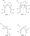
FIG. 1 is a top perspective view of a surgical tack in accordance with the present disclosure; -
FIG. 2 is a front elevational view of the surgical tack shown inFIG. 1 ; -
FIG. 3 is a side elevational view of the surgical tack shown inFIG. 1 ; -
FIG. 4 is a top plan view of the surgical tack shown inFIG. 1 ; -
FIG. 5 is a perspective view of a preferred embodiment of a tack applier in accordance with the present disclosure; -
FIG. 5A is a side cross-sectional view of the tack applier ofFIG. 5 ; -
FIG. 6 is a partial cross-sectional perspective view of a distal end of the tack applier shown inFIG. 6 with a surgical tack, shown inFIG. 1 , partially fired through a surgical mesh and into body tissue; -
FIG. 6A is a top cross-sectional view of the distal end of the tack applier ofFIG. 6 showing a single tack disposed in the channels; -
FIG. 7 is a partial cross-sectional perspective view of a distal end of the tacker shown inFIG. 5 with a surgical tack shown inFIG. 1 completely fired into the surgical mesh and the body tissue; -
FIG. 8 is a perspective view of a surgical tack, in accordance with the present disclosure, as it would appear after having been driven into body tissue; -
FIG. 9 is a front elevational view of the surgical tack shown inFIG. 8 ; and -
FIG. 10 is a top plan view of the surgical tack shown inFIG. 8 . - Preferred embodiments of the presently disclosed surgical tack will now be described in detail with reference to the drawing figures wherein like reference numerals identify similar or identical elements. Referring now in detail to
FIGS. 1-4 , a surgical fastener or tack in accordance with the present disclosure is generally designated as 100. As used herein, the term "distal" refers to that portion of the tack, tacker, or applier which is further from the user while the term "proximal" refers to that portion which is closer to the user. -
Surgical tack 100 includes a pair oflegs 102 and anarcuate cross-member 104 whose ends are interconnected to or joined withproximal ends 108 oflegs 102.Legs 102 are substantially parallel to one another in a spaced apart relationship and each terminates at a distal end in a sharpenedtip 106. While it is shown that eachleg 102 has a generally circular cross-sectional profile, other cross-sectional profiles can be employed, e.g., rectangular, triangular, oval, etc. Although eachtip 106 is shown as sharpened and conical, other tip profiles can be employed, e.g., rectangular, angled, rounded or the like. Acenterline 120 bisects cross-member 104 and is substantially equidistant from the proximal ends of 108 oflegs 102. -
Arcuate cross-member 104 is oriented such that a plane defined byarcuate cross-member 104 is substantially orthogonal to the planes defined byrespective legs 102. In particular, with reference toFIG. 3 , the plane ofarcuate cross-member 104 is disposed at an angle θ with respect to the plane defined between the pair oflegs 102. In the preferred embodiment shown, angle θ is 90° such that the underlying surface ofcross-member 104 can rest flush against a surgical mesh and underlying body tissue whensurgical tack 100 is fully inserted into the same. Less preferably, the plane ofcross-member 104 can be oriented at either an acute or an obtuse angle with respect to the plane defined bylegs 102. - As seen in
FIG. 2 , eachleg 102 is disposed at an angle ϕ with respect to the plane ofarcuate cross-member 104. In the preferred embodiment, angle ϕ is 90°. However, it is envisioned that the distal end of eachleg 102 can be spaced further apart than the distance between proximal ends, 108 of legs 102 (i.e., having an angle ϕ greater than 90°), be spaced closer together than the distance between proximal ends 108 (i.e., having an angle ϕ less than 90°) or be shifted a distance laterally with respect to proximal ends 108 (i.e., having an angle ϕ of one leg which is less than 90° and an angle ϕ of the other leg which is greater than 90°). - It is contemplated in the preferred embodiment that
surgical tack 100 is made from a semi-stiff pliable wire, such as titanium. Examples of other materials that can be used in constructingsurgical tack 100 include titanium alloys, stainless steel, nickel, chrome alloys, and any other biocompatible implantable metals. Other options for materials include liquid crystal polymers such as polyglycolic acid, polylactic acid, and polyglycolide (poly(hydroxyacetic acid)) all of which are bioabsorbable materials. It may be desired to coat the surgical tack, or a portion thereof, with a biocompatible lubricious material that provides for easier delivery of the surgical tack into the body tissue. - It is further contemplated that
surgical tack 100 can be made of a shape memory alloy. The surgical tack would have a pair of evenly spaced apart parallel legs while stored in the applying apparatus and, as the surgical tack contacts the warm body tissue or fluid during insertion, the shape memory of the surgical tack material would cause the pair of legs of the surgical tack to be drawn in toward one another. Alternately, the surgical tack made from the shape memory alloy could cause the pair of legs of the surgical tack to diverge apart from one another when the surgical tack contacts the warm body tissue or fluid during insertion. - With respect now to
FIGS. 5-7 and initially with respect toFIG. 5 , there is disclosed a preferred embodiment of a surgical tack applier generally designated 200.Surgical tack applier 200 is provided to secure a surgical mesh to tissue during surgical procedures such as hernia repair.Tack applier 200 generally includes ahousing 202 and ahandle portion 204 extending fromhousing 202. Atrigger 206 is pivotably connected tohousing 202 with a free end oftrigger 206 spaced from a free end ofhandle portion 204. - Tack applier 200 (
FIG. 5A ) further includes an elongatedtubular portion 208 having adistal tip 234 and extending distally fromhousing 202. Elongatedtubular portion 208 is provided to house or retain a plurality ofsurgical tacks 100, in accordance with the present disclosure, for application to body tissue. Elongatedtubular portion 208 is preferably dimensioned to fit through conventional cannula structures used in hernia repair techniques.Proximal portion 202 includeshandle portion 204 and anactuator 232 operably connected to adrive rod 218 disposed inside of elongatedtubular portion 208 and having a plurality ofsurgical tacks 100 mounted therein. In general, through the manipulation ofactuator 232,surgical tacks 100 are ejected, one by one, out ofdistal tip 234 and into body tissue.Tack applier 200, hereinafter described in more detail, is equally proficient in driving each of the embodiments ofsurgical tacks 100 set forth above into tissue. In the preferred embodiment of theproximal portion 202 of the tack applier, atrigger 206 is pivotally connected about amidpoint 256 to handleportion 204. Afirst end 254 oftrigger 206 is to be configured for gripping by hand. Asecond end 260 oftrigger 206 is to be adapted for pivotally engaging anut driver 262. -
Nut driver 262 oftack applier 200 travels upon a high helixlead screw 264 that is rotatably mounted withinproximal portion 202. In the preferred embodiment, a longitudinal axis of high helixlead screw 264 is coaxial with a longitudinal axis extending throughdistal tip 234 oftack applier 200. Upon manipulation oftrigger 206,nut driver 262 travels alonglead screw 264 causing it to rotate. Through a connection oflead screw 264 to drive rod 218 (seeFIG. 6 ), the action oflead screw 264 causes driverod 218 to rotate.Lead screw 264 may be connected to driverod 218 by any conventional means. For instance,lead screw 264 can have an internal bore receiving and engaging an end ofdrive rod 218. Further, the length of travel ofnut driver 262 alonglead screw 264 is chosen such that it causes the rotator to rotate a predetermined number of times so that with each full throw oftrigger 206, one of the plurality ofsurgical tacks 100 is ejected fromtack applier 200. - Additionally, in the preferred embodiment, trigger 206 further includes a
midsection extension 266. Pivotally attached tomidsection extension 266 oftrigger 206 is contemplated to be a spring loadedpawl 268 adapted to releasably engagegear teeth 278 formed in the interior ofhandle portion 204. Spring loadedpawl 268 is configured to prohibittrigger 206 from backstroking until it has been completely depressed. Upon complete depression oftrigger 206,pawl 268 clearsgear teeth 278 and the spring biasing ofpawl 268 rotatespawl 268 away fromteeth 278, thereby allowingtrigger 206 to return to its undepressed condition. - In operation, upon complete depression of
trigger 206,nut driver 262 travels a predetermined distance alonglead screw 264, causingdrive rod 218 to rotate a pre-determined number of revolutions corresponding to a number of turns needed to advance a particular distalmostsurgical tack 100 fromdistal end 234 oftubular portion 208. Asdrive rod 218 rotates,surgical tacks 100 are retained in the groove ofdrive rod 218, advance distally in the groove ofdrive rod 218 towarddistal end 234, and the most distalsurgical tack 100 is threaded out ofdistal tip 234 oftack applier 200 and into tissue. Moreover, wheretrigger 206 is only partially depressed, spring loadedpawl 268 operates to holdtrigger 206 stationary and will continue to function to holdtrigger 206 stationary untiltrigger 206 has been completely depressed. In this way, the delivery ofsurgical tacks 100 into body tissue is controlled so that only one of the plurality ofsurgical tacks 100 may be completely ejected out oftack applier 200 and pressed into body tissue at a time. - In the preferred embodiment,
proximal portion 202 is fabricated to have a reusable handle that can be re-sterilized, andtubular portion 208 is made disposable. Thus, upon discharge of allsurgical tacks 100 fromdistal tip 234,tubular portion 208 can be discarded and replaced. The handle could be reused up to a limited number of procedures. - Referring now in particular to
FIGS. 6, 6A, and 7 , elongatedtubular portion 208 retains a plurality ofsurgical tacks 100 and is adapted to drivesurgical tacks 100 into tissue. As seen inFIGS. 6 and 7 , elongatedtubular portion 208 can be or include a generallytubular sleeve 210 defining abore 212 therethrough, ajacket 214 having amain channel 215 and which is preferably brazed or welded to aninner surface 216 oftubular sleeve 210, and arotatable drive rod 218 having protruding helical threads and extending concentrically longitudinally throughtubular sleeve 210 andmain channel 215 ofjacket 214. Whilejacket 214 has been disclosed as being brazed or welded withintubular sleeve 210, it is envisioned that any means for fixingjacket 214 withintubular sleeve 210 can be used, for example, peening, gluing, male/female fixation or attachment, etc. Alternately,jacket 214 andtubular sleeve 210 may be of unitary construction. -
Main channel 215 ofjacket 214 includes a pair of longitudinally extendingsub channels 220 formed into an inner surface ofmain channel 215. Eachsub channel 220 preferably extends substantially the entire length oftubular sleeve 210 is adapted to receive at least a portion of a respective one oflegs 102 ofsurgical tack 100 therein. Preferably,sub channels 220 are oriented 180 degrees apart. However, it is envisioned that the radial angular orientation of the pair ofsub channels 220 can be any radial distance. Depending on the radial angular orientation of the pair ofsub channels 220, the radial angular length ofarcuate cross member 104 is selected such that eachleg 102 ofsurgical tack 100 is received in a respective one of said pair ofsub channels 220. Accordingly, it is envisioned that if the radial angular length between the pair ofsub channels 220 is less than 180 degrees, two pairs of longitudinally extending sub channels (not shown) can be formed along the inner surface ofjacket 214 such that two offset columns ofsurgical tacks 100 can be arranged within and applied from the same elongatetubular portion 208, even substantially simultaneously. - Another embodiment for providing a supply of
surgical tacks 100 includes providing interchangeable or replaceabletubular portions 208. Interchangeabletubular portions 208 may have threaded connections for attachment to housing 202 oftack applier 200. In addition, quick-release connections that are known in the art may also be used for attachingtubular portion 208 to tackapplier 200. An alternate embodiment includes cassettes or other easily replaceable containers or cartridges containing a quantity ofsurgical tacks 100 that are configured and adapted for feedingsurgical tacks 100 to driverod 218. Preferably, the replaceable items would includedrive rod 218, withtacks 100 engaged its helical threads andjacket 214 encompassing the tacks and rod. Clips, screws, snaps, and other suitable means can be employed for removably attachingjacket 214 totubular portion 208. - Drive
rod 218 preferably includes athread 224 extending longitudinally along the entire outer surface thereof.Thread 224 defines ahelical groove 226 having a depth and a pitch selected to receivearcuate cross member 104 ofsurgical tack 100 therein. Preferably,surgical tacks 100 will be adapted such that each of the pair oflegs 102 is received in arespective sub channel 220 ofjacket 214 and such that the angle ϕ of thearcuate cross member 104 with respect tolegs 102 is equal to the pitch ofthread 224. - As best shown in
FIG. 6 , a plurality ofsurgical tacks 100 may be arranged longitudinally along the length ofdrive rod 218 with eachsurgical tack 100 having arespective leg 102 positioned within arespective sub channel 220 andarcuate cross member 104 positioned withinhelical groove 226. In this loaded position,surgical tack 100 is defined as being in a pre-fonned configuration and ready for use. - The operation of
tack applier 200 is best seen with reference toFIGS. 6 and 7 . Initially as seen inFIG. 6 , the distal end of elongatetubular portion 208 is pressed into contact against surgical mesh M and body tissueT. Drive rod 218 is then rotated by squeezingtrigger 206 againsthandle portion 204. Sincelegs 102 ofsurgical tack 100 are seated withinsub channels 220 ofjacket 214,surgical tacks 100 are prevented from rotating together withdrive rod 218 withinjacket 214 andtubular sleeve 210 andsurgical tack 100 is moved distally and eventually expelled therefrom. Meanwhile,arcuate cross member 104 ofsurgical tack 100 is seated withinhelical groove 226 thereby causingsurgical tack 100 to be advanced distally throughtubular sleeve 210 by the rotational force applied tosurgical tacks 100 bydrive rod 218. Initially, as the pair oflegs 102 ofsurgical tack 100 is driven through surgical mesh M and into body tissue T, thelegs 102 remain parallel to one another. Left alone, the legs will tend to remain in that disposition as they are driven into the mesh and tissue. However, assurgical tack 100 advances further into body tissue T by exitingdistal tip 234 oftubular portion 208, eachleg 102 can be deflected by an optimal radially inwardly tapered or concavely curved lip "L" (dashed line) towardcenterline 120 ofsurgical tack 100 defining a formed configuration ofsurgical tack 100. Preferably, eachtip 106 crosses centerline 120 thereby better securingsurgical tack 100 in body tissue T (seeFIG. 7 ). In other words, by the pair oflegs 102 crossing one another, surgical mesh M and body tissue T are trapped therebetween. Sincelegs 102 are merely deflected towards one another and not deformed into a different shape,surgical tack 100 can be withdrawn from body tissue T without or with minimum damage thereto. - As discussed above,
surgical tacks 100 can be formed of a shape memory material such that, whenlegs 102 ofsurgical tack 100 contact the warm body tissue T, the legs will automatically deflect towards one another or diverge away from each other. Alternatively, it is envisioned that mechanical deflecting means, e.g., lip "L" can be provided at the distal end ofjacket 214 or of the elongatedtubular portion 208, to urge the pair oflegs 102 ofsurgical tack 100, whether or not made of shape memory material, towards one another as the pair oflegs 102 begin to pass through surgical mesh M and begin to penetrate body tissue T. -
FIGS. 8-10 show asurgical tack 100, after having been driven through surgical mesh M and into body tissue T and having had itslegs 102 deflected towards one another. While thelegs 102 have been shown as overlapping one another, it is envisioned that the pair oflegs 102 can be simply brought closer to one another. - It will be understood that various modifications may be made to the embodiments disclosed herein. For example, it is envisioned that
surgical tack applier 200 is provided with a removable cartridge (not shown) including a removable jacket having a drive rod and a plurality ofsurgical tacks 100. The jacket can be removable attached to elongatedtubular member 208 by any suitable means including snaps, clips, hooks, bolts, etc. Alternatively, elongatetubular portion 208 ofapplier 200, that has expelled all of itssurgical tacks 100, is replaceable with anothertubular portion 208 filled with newsurgical tacks 100. Thus, the above description should not be construed as limiting, but merely as an exemplification of preferred embodiments. Those skilled in the art will envision other modifications within the scope of the claims appended hereto.
Claims (11)
- A surgical fastener system comprising a surgical fastener (100) and a surgical fastener applier (200); the surgical fastener for securing mesh material to body tissue, comprising:a surgical tack (100) having a pre-formed configuration and a formed configuration, the surgical tack in its pre-formed configuration including a pair of legs (102) having a proximal end (108) and a free distal end (106), the legs defining a vertical plane and further defining a centerline (120) existing in the vertical plane, the centerline being substantially equidistant between the legs wherein the legs are substantially parallel to one another and substantially parallel to the centerline, and the surgical tack further including an arcuate cross-member (104) interconnecting proximal ends of the legs and defining a plane at an angle with respect to the vertical plane defined by the legs; andthe surgical tack in its formed configuration including the legs deflected towards one another;
such that when the surgical tack is driven through a mesh in its pre-formed configuration, the surgical tack is formed in its formed configuration; and
the surgical fastener applier, comprising:a housing (202);an elongate tubular portion (208) having a proximal end and a distal end (234), the elongate tubular portion comprising:a bore therethrough;an elongate jacket (214) having an inner surface defining a longitudinal main channel (215) extending through the jacket, the main channel being adapted to receive the surgical fastener, the main channel having an inner surface that includes a pair of longitudinally extending sub channels (220) formed along the inner surface, each of the pair of sub channels being adapted to receive at least a portion of a respective one of the pair of legs of the surgical fastener therein;a rotatable drive rod (218) having a proximal end and a distal end, the drive rod extending axially through the jacket, the drive rod including a longitudinally extending helical thread (224), the helical thread defining a groove (226) that is adapted to receive the arcuate cross-member of the surgical fastener therein; anda mechanism (206, 262, 264) operatively connected to the drive rod for rotating the drive rod to drive fasteners legs first from the distal end of the drive rod and from the distal end of the tubular portion. - The surgical fastener and surgical fastener applier according to claim 1, wherein the arcuate cross-member is oriented substantially orthogonal to the vertical plane defined by the pair of legs.
- The surgical fastener and surgical fastener applier according to claim 1 or 2, wherein the distal ends of the legs are provided with a pointed tip.
- The surgical fastener and surgical fastener applier according to claim 1, 2 or 3, wherein the surgical tack is made from a shape memory material.
- The surgical fastener and surgical fastener applier according to claim 1, 2, 3 or 4, wherein the surgical tack is made from a bio-absorbable material.
- The surgical fastener and surgical fastener applier according to claim 5, wherein the bioabsorbable material is selected from the group consisting of polyglycolic acid, poly actic acid, and polyglycolide.
- The surgical fastener and surgical fastener applier according to any one of the preceding claims, wherein the pair of sub channels of the jacket are diametrically opposed.
- The surgical fastener and surgical fastener applier according to any one of the preceding claims, wherein the jacket includes a plurality of pairs of sub channels formed along the inner surface thereof, wherein each pair of sub channels is at least less than 180 degrees apart from one another.
- The surgical fastener and surgical fastener applier according to any one of the preceding claims, wherein the mechanism includes a trigger (206) pivotably coupled to the surgical applier.
- The surgical fastener and surgical fastener applier according to any one of the preceding claims, wherein the applier further comprises a mechanical deforming means (L) operatively coupled to a distal end of the jacket, the deforming means being adapted to deflect the pair of legs of the surgical fastener toward one another as the surgical fastener is expelled from the distal end of the elongate tubular member.
- The surgical fastener and surgical fastener applier according to claim 10, wherein the mechanical deforming means includes radially inwardly directed lips (L).
Applications Claiming Priority (3)
| Application Number | Priority Date | Filing Date | Title |
|---|---|---|---|
| US37467202P | 2002-04-22 | 2002-04-22 | |
| US374672P | 2002-04-22 | ||
| PCT/US2003/012644 WO2003088846A1 (en) | 2002-04-22 | 2003-04-22 | Tack and tack applier |
Publications (3)
| Publication Number | Publication Date |
|---|---|
| EP1496807A1 EP1496807A1 (en) | 2005-01-19 |
| EP1496807A4 EP1496807A4 (en) | 2009-04-01 |
| EP1496807B1 true EP1496807B1 (en) | 2017-01-04 |
Family
ID=29251218
Family Applications (1)
| Application Number | Title | Priority Date | Filing Date |
|---|---|---|---|
| EP03747056.4A Expired - Fee Related EP1496807B1 (en) | 2002-04-22 | 2003-04-22 | Tack and tack applier |
Country Status (4)
| Country | Link |
|---|---|
| US (2) | US7229452B2 (en) |
| EP (1) | EP1496807B1 (en) |
| AU (1) | AU2003231752A1 (en) |
| WO (1) | WO2003088846A1 (en) |
Cited By (2)
| Publication number | Priority date | Publication date | Assignee | Title |
|---|---|---|---|---|
| CN108273186A (en) * | 2017-01-05 | 2018-07-13 | 柯惠Lp公司 | Fastener, applicator and method are can plant for plesioradiotherapy volume |
| CN110859650A (en) * | 2019-11-27 | 2020-03-06 | 苏州森锋医疗器械有限公司 | Anastomosis nail |
Families Citing this family (169)
| Publication number | Priority date | Publication date | Assignee | Title |
|---|---|---|---|---|
| US7842068B2 (en) | 2000-12-07 | 2010-11-30 | Integrated Vascular Systems, Inc. | Apparatus and methods for providing tactile feedback while delivering a closure device |
| US6461364B1 (en) | 2000-01-05 | 2002-10-08 | Integrated Vascular Systems, Inc. | Vascular sheath with bioabsorbable puncture site closure apparatus and methods of use |
| US6391048B1 (en) | 2000-01-05 | 2002-05-21 | Integrated Vascular Systems, Inc. | Integrated vascular device with puncture site closure component and sealant and methods of use |
| US8758400B2 (en) | 2000-01-05 | 2014-06-24 | Integrated Vascular Systems, Inc. | Closure system and methods of use |
| US9579091B2 (en) | 2000-01-05 | 2017-02-28 | Integrated Vascular Systems, Inc. | Closure system and methods of use |
| US6626918B1 (en) | 2000-10-06 | 2003-09-30 | Medical Technology Group | Apparatus and methods for positioning a vascular sheath |
| US7905900B2 (en) | 2003-01-30 | 2011-03-15 | Integrated Vascular Systems, Inc. | Clip applier and methods of use |
| US8690910B2 (en) | 2000-12-07 | 2014-04-08 | Integrated Vascular Systems, Inc. | Closure device and methods for making and using them |
| US7367939B2 (en) * | 2004-06-14 | 2008-05-06 | Ethicon Endo-Surgery, Inc. | Rotational, translational and torqueing control members for an endoscopic instrument |
| US6749621B2 (en) | 2002-02-21 | 2004-06-15 | Integrated Vascular Systems, Inc. | Sheath apparatus and methods for delivering a closure device |
| US8758398B2 (en) | 2006-09-08 | 2014-06-24 | Integrated Vascular Systems, Inc. | Apparatus and method for delivering a closure element |
| US8202293B2 (en) | 2003-01-30 | 2012-06-19 | Integrated Vascular Systems, Inc. | Clip applier and methods of use |
| US8398656B2 (en) | 2003-01-30 | 2013-03-19 | Integrated Vascular Systems, Inc. | Clip applier and methods of use |
| US8905937B2 (en) | 2009-02-26 | 2014-12-09 | Integrated Vascular Systems, Inc. | Methods and apparatus for locating a surface of a body lumen |
| US8821534B2 (en) | 2010-12-06 | 2014-09-02 | Integrated Vascular Systems, Inc. | Clip applier having improved hemostasis and methods of use |
| CA2527778C (en) * | 2003-06-13 | 2011-11-08 | Tyco Healthcare Group Lp | Multiple member interconnect for surgical instrument and absorbable screw fastener |
| US8216255B2 (en) * | 2004-06-14 | 2012-07-10 | Ethicon Endo-Surgery, Inc. | Endoscopic clip applier actuator |
| US8608797B2 (en) | 2005-03-17 | 2013-12-17 | Valtech Cardio Ltd. | Mitral valve treatment techniques |
| US8313497B2 (en) | 2005-07-01 | 2012-11-20 | Abbott Laboratories | Clip applier and methods of use |
| US8951285B2 (en) | 2005-07-05 | 2015-02-10 | Mitralign, Inc. | Tissue anchor, anchoring system and methods of using the same |
| WO2007131110A2 (en) | 2006-05-03 | 2007-11-15 | Raptor Ridge, Llc | Systems and methods of tissue closure |
| US8348973B2 (en) | 2006-09-06 | 2013-01-08 | Covidien Lp | Bioactive substance in a barbed suture |
| DE602007001747D1 (en) | 2006-09-06 | 2009-09-10 | Tyco Healthcare | Surgical suture with barbs |
| US10130359B2 (en) | 2006-09-29 | 2018-11-20 | Ethicon Llc | Method for forming a staple |
| US8348131B2 (en) * | 2006-09-29 | 2013-01-08 | Ethicon Endo-Surgery, Inc. | Surgical stapling instrument with mechanical indicator to show levels of tissue compression |
| US11259924B2 (en) | 2006-12-05 | 2022-03-01 | Valtech Cardio Ltd. | Implantation of repair devices in the heart |
| US9883943B2 (en) | 2006-12-05 | 2018-02-06 | Valtech Cardio, Ltd. | Implantation of repair devices in the heart |
| WO2010004546A1 (en) | 2008-06-16 | 2010-01-14 | Valtech Cardio, Ltd. | Annuloplasty devices and methods of delivery therefor |
| US11660190B2 (en) | 2007-03-13 | 2023-05-30 | Edwards Lifesciences Corporation | Tissue anchors, systems and methods, and devices |
| WO2009011824A1 (en) * | 2007-07-13 | 2009-01-22 | The Brigham And Women's Hospital, Inc. | System and method for hernia mesh fixation |
| US8152775B2 (en) | 2007-10-17 | 2012-04-10 | Tyco Healthcare Group Lp | Access port using shape altering anchor |
| EP2058015B1 (en) * | 2007-11-05 | 2014-01-08 | Covidien LP | Novel surgical fastener |
| US20090177201A1 (en) * | 2007-11-14 | 2009-07-09 | Michael Soltz | Staple with Multiple Cross Sectional Shapes |
| US8561870B2 (en) * | 2008-02-13 | 2013-10-22 | Ethicon Endo-Surgery, Inc. | Surgical stapling instrument |
| US9301826B2 (en) | 2008-02-18 | 2016-04-05 | Covidien Lp | Lock bar spring and clip for implant deployment device |
| US9393002B2 (en) | 2008-02-18 | 2016-07-19 | Covidien Lp | Clip for implant deployment device |
| US9398944B2 (en) | 2008-02-18 | 2016-07-26 | Covidien Lp | Lock bar spring and clip for implant deployment device |
| EP2247245B1 (en) | 2008-02-18 | 2017-06-28 | Covidien LP | A device for deploying and attaching a patch to a biological tissue |
| US9034002B2 (en) | 2008-02-18 | 2015-05-19 | Covidien Lp | Lock bar spring and clip for implant deployment device |
| US8317808B2 (en) | 2008-02-18 | 2012-11-27 | Covidien Lp | Device and method for rolling and inserting a prosthetic patch into a body cavity |
| US9833240B2 (en) | 2008-02-18 | 2017-12-05 | Covidien Lp | Lock bar spring and clip for implant deployment device |
| US9044235B2 (en) | 2008-02-18 | 2015-06-02 | Covidien Lp | Magnetic clip for implant deployment device |
| US9393093B2 (en) | 2008-02-18 | 2016-07-19 | Covidien Lp | Clip for implant deployment device |
| US8808314B2 (en) | 2008-02-18 | 2014-08-19 | Covidien Lp | Device and method for deploying and attaching an implant to a biological tissue |
| US8758373B2 (en) | 2008-02-18 | 2014-06-24 | Covidien Lp | Means and method for reversibly connecting a patch to a patch deployment device |
| US8273105B2 (en) | 2008-02-20 | 2012-09-25 | Tyco Healthcare Group Lp | Compound barb medical device and method |
| US8888810B2 (en) | 2008-02-20 | 2014-11-18 | Covidien Lp | Compound barb medical device and method |
| US8454653B2 (en) | 2008-02-20 | 2013-06-04 | Covidien Lp | Compound barb medical device and method |
| US8382829B1 (en) | 2008-03-10 | 2013-02-26 | Mitralign, Inc. | Method to reduce mitral regurgitation by cinching the commissure of the mitral valve |
| US7857186B2 (en) | 2008-09-19 | 2010-12-28 | Ethicon Endo-Surgery, Inc. | Surgical stapler having an intermediate closing position |
| PL3476312T3 (en) | 2008-09-19 | 2024-03-11 | Ethicon Llc | Surgical stapler with apparatus for adjusting staple height |
| EP2792307B1 (en) | 2008-10-20 | 2017-10-04 | Covidien LP | A device for attaching a patch to a biological tissue |
| US8398676B2 (en) | 2008-10-30 | 2013-03-19 | Abbott Vascular Inc. | Closure device |
| US8911494B2 (en) | 2009-05-04 | 2014-12-16 | Valtech Cardio, Ltd. | Deployment techniques for annuloplasty ring |
| US9011530B2 (en) | 2008-12-22 | 2015-04-21 | Valtech Cardio, Ltd. | Partially-adjustable annuloplasty structure |
| US8940044B2 (en) | 2011-06-23 | 2015-01-27 | Valtech Cardio, Ltd. | Closure element for use with an annuloplasty structure |
| US10517719B2 (en) | 2008-12-22 | 2019-12-31 | Valtech Cardio, Ltd. | Implantation of repair devices in the heart |
| EP2379008B1 (en) | 2008-12-22 | 2021-02-17 | Valtech Cardio, Ltd. | Adjustable annuloplasty devices |
| US8241351B2 (en) | 2008-12-22 | 2012-08-14 | Valtech Cardio, Ltd. | Adjustable partial annuloplasty ring and mechanism therefor |
| US8715342B2 (en) | 2009-05-07 | 2014-05-06 | Valtech Cardio, Ltd. | Annuloplasty ring with intra-ring anchoring |
| US20100191332A1 (en) | 2009-01-08 | 2010-07-29 | Euteneuer Charles L | Implantable Tendon Protection Systems and Related Kits and Methods |
| US20100185234A1 (en) | 2009-01-16 | 2010-07-22 | Abbott Vascular Inc. | Closure devices, systems, and methods |
| FR2941144B1 (en) * | 2009-01-22 | 2012-04-27 | Sofradim Production | SURGICAL STAPLER FOR PREPOSITIONING AND ATTACHING TEXTILE PROSTHESIS, METHOD OF LOADING THE SAME, AND SELF-AGRIPPTING SURGICAL STRAIN |
| US8353956B2 (en) | 2009-02-17 | 2013-01-15 | Valtech Cardio, Ltd. | Actively-engageable movement-restriction mechanism for use with an annuloplasty structure |
| US9179910B2 (en) | 2009-03-20 | 2015-11-10 | Rotation Medical, Inc. | Medical device delivery system and method |
| WO2013069019A2 (en) | 2011-11-08 | 2013-05-16 | Valtech Cardio, Ltd. | Controlled steering functionality for implant-delivery tool |
| US9968452B2 (en) | 2009-05-04 | 2018-05-15 | Valtech Cardio, Ltd. | Annuloplasty ring delivery cathethers |
| US8523881B2 (en) | 2010-07-26 | 2013-09-03 | Valtech Cardio, Ltd. | Multiple anchor delivery tool |
| US8728099B2 (en) | 2009-05-12 | 2014-05-20 | Ethicon, Inc. | Surgical fasteners, applicator instruments, and methods for deploying surgical fasteners |
| US9055945B2 (en) | 2009-05-12 | 2015-06-16 | Ethicon, Inc. | Surgical fasteners having articulating joints and deflectable tips |
| US8728098B2 (en) * | 2009-05-12 | 2014-05-20 | Ethicon, Inc. | Surgical fasteners, applicator instruments, and methods for deploying surgical fasteners |
| US8920439B2 (en) | 2009-05-12 | 2014-12-30 | Ethicon, Inc. | Applicator instruments having curved and articulating shafts for deploying surgical fasteners and methods therefor |
| USD698021S1 (en) | 2009-05-12 | 2014-01-21 | Ethicon, Inc. | Surgical fastener |
| USD744646S1 (en) | 2009-05-12 | 2015-12-01 | Ethicon, Inc. | Surgical fastener |
| US8894669B2 (en) | 2009-05-12 | 2014-11-25 | Ethicon, Inc. | Surgical fasteners, applicator instruments, and methods for deploying surgical fasteners |
| US8579920B2 (en) | 2009-05-12 | 2013-11-12 | Ethicon, Inc. | Surgical fasteners, applicator instruments, and methods for deploying surgical fasteners |
| WO2010141906A1 (en) | 2009-06-04 | 2010-12-09 | Rotation Medical, Inc. | Methods and apparatus for deploying sheet-like materials |
| CA2763919C (en) | 2009-06-04 | 2017-05-23 | Rotation Medical, Inc. | Apparatus for fixing sheet-like materials to a target tissue |
| EP2445417A2 (en) * | 2009-06-26 | 2012-05-02 | QuickRing Medical Technologies Ltd. | Surgical stapler |
| US8474679B2 (en) * | 2009-07-13 | 2013-07-02 | C.R. Bard, Inc. | Instrument for applying a surgical fastener |
| US20110034941A1 (en) * | 2009-08-10 | 2011-02-10 | Joseph Iraci | Surgical Instrument for Hernia Repair and Method |
| US8459524B2 (en) | 2009-08-14 | 2013-06-11 | Covidien Lp | Tissue fastening system for a medical device |
| WO2011021083A1 (en) | 2009-08-17 | 2011-02-24 | PolyTouch Medical, Inc. | Articulating patch deployment device and method of use |
| EP2467066B1 (en) | 2009-08-17 | 2019-03-27 | Covidien LP | Means for reversibly connecting an implant to a deployment device |
| US20110054492A1 (en) | 2009-08-26 | 2011-03-03 | Abbott Laboratories | Medical device for repairing a fistula |
| US10098737B2 (en) | 2009-10-29 | 2018-10-16 | Valtech Cardio, Ltd. | Tissue anchor for annuloplasty device |
| US9180007B2 (en) | 2009-10-29 | 2015-11-10 | Valtech Cardio, Ltd. | Apparatus and method for guide-wire based advancement of an adjustable implant |
| US9011520B2 (en) | 2009-10-29 | 2015-04-21 | Valtech Cardio, Ltd. | Tissue anchor for annuloplasty device |
| WO2011067770A1 (en) | 2009-12-02 | 2011-06-09 | Valtech Cardio, Ltd. | Delivery tool for implantation of spool assembly coupled to a helical anchor |
| US8870950B2 (en) | 2009-12-08 | 2014-10-28 | Mitral Tech Ltd. | Rotation-based anchoring of an implant |
| US8683895B2 (en) * | 2010-02-23 | 2014-04-01 | Kensey Nash Corporation | Single revolution snap action drive for surgical fasteners |
| US8403945B2 (en) | 2010-02-25 | 2013-03-26 | Covidien Lp | Articulating endoscopic surgical clip applier |
| US9198750B2 (en) | 2010-03-11 | 2015-12-01 | Rotation Medical, Inc. | Tendon repair implant and method of arthroscopic implantation |
| US11653910B2 (en) | 2010-07-21 | 2023-05-23 | Cardiovalve Ltd. | Helical anchor implantation |
| US9198751B2 (en) | 2011-02-15 | 2015-12-01 | Rotation Medical, Inc. | Methods and apparatus for delivering and positioning sheet-like materials in surgery |
| US8617184B2 (en) * | 2011-02-15 | 2013-12-31 | Abbott Cardiovascular Systems, Inc. | Vessel closure system |
| CA2825918C (en) | 2011-02-15 | 2018-08-07 | Rotation Medical, Inc. | Methods and apparatus for delivering and positioning sheet-like materials |
| WO2012145059A1 (en) | 2011-02-15 | 2012-10-26 | Rotation Medical, Inc. | Methods and apparatus for fixing sheet-like materials to a target tissue |
| US10952783B2 (en) | 2011-12-29 | 2021-03-23 | Rotation Medical, Inc. | Guidewire having a distal fixation member for delivering and positioning sheet-like materials in surgery |
| US9149276B2 (en) | 2011-03-21 | 2015-10-06 | Abbott Cardiovascular Systems, Inc. | Clip and deployment apparatus for tissue closure |
| US10792152B2 (en) | 2011-06-23 | 2020-10-06 | Valtech Cardio, Ltd. | Closed band for percutaneous annuloplasty |
| US9855036B2 (en) * | 2013-11-13 | 2018-01-02 | Arthrex, Inc. | Staples for generating and applying compression within a body |
| US8858623B2 (en) | 2011-11-04 | 2014-10-14 | Valtech Cardio, Ltd. | Implant having multiple rotational assemblies |
| WO2013096219A1 (en) | 2011-12-19 | 2013-06-27 | Rotation Medical, Inc. | Apparatus and method for forming pilot holes in bone and delivering fasteners therein for retaining an implant |
| US9107661B2 (en) | 2011-12-19 | 2015-08-18 | Rotation Medical, Inc. | Fasteners and fastener delivery devices for affixing sheet-like materials to bone or tissue |
| AU2012369140B2 (en) | 2011-12-19 | 2016-11-10 | Rotation Medical, Inc. | Fasteners for affixing sheet -like materials to bone or tissue |
| US9271726B2 (en) | 2011-12-19 | 2016-03-01 | Rotation Medical, Inc. | Fasteners and fastener delivery devices for affixing sheet-like materials to bone or tissue |
| WO2013101641A2 (en) | 2011-12-29 | 2013-07-04 | Rotation Medical, Inc. | Anatomical location markers and methods of use in positioning sheet-like materials during surgery |
| WO2014052818A1 (en) | 2012-09-29 | 2014-04-03 | Mitralign, Inc. | Plication lock delivery system and method of use thereof |
| WO2014064695A2 (en) | 2012-10-23 | 2014-05-01 | Valtech Cardio, Ltd. | Percutaneous tissue anchor techniques |
| EP3517052A1 (en) | 2012-10-23 | 2019-07-31 | Valtech Cardio, Ltd. | Controlled steering functionality for implant-delivery tool |
| US9730793B2 (en) | 2012-12-06 | 2017-08-15 | Valtech Cardio, Ltd. | Techniques for guide-wire based advancement of a tool |
| US9364209B2 (en) | 2012-12-21 | 2016-06-14 | Abbott Cardiovascular Systems, Inc. | Articulating suturing device |
| US9351733B2 (en) | 2013-01-18 | 2016-05-31 | Covidien Lp | Surgical fastener applier |
| US9681952B2 (en) | 2013-01-24 | 2017-06-20 | Mitraltech Ltd. | Anchoring of prosthetic valve supports |
| WO2014134183A1 (en) | 2013-02-26 | 2014-09-04 | Mitralign, Inc. | Devices and methods for percutaneous tricuspid valve repair |
| US10449333B2 (en) | 2013-03-14 | 2019-10-22 | Valtech Cardio, Ltd. | Guidewire feeder |
| US9364235B2 (en) | 2013-03-14 | 2016-06-14 | C.R. Bard, Inc. | Power assist device for a surgical instrument |
| EP2968847B1 (en) | 2013-03-15 | 2023-03-08 | Edwards Lifesciences Corporation | Translation catheter systems |
| US9655621B2 (en) * | 2013-03-15 | 2017-05-23 | Covidien Lp | Surgical instrument for dispensing tacks and solution |
| CN103315787A (en) * | 2013-06-06 | 2013-09-25 | 常熟市亨利医疗器械有限公司 | Absorbable suturing nail |
| US10070857B2 (en) | 2013-08-31 | 2018-09-11 | Mitralign, Inc. | Devices and methods for locating and implanting tissue anchors at mitral valve commissure |
| US11051814B2 (en) | 2013-09-16 | 2021-07-06 | Oregon Health & Science University | Bioabsorbable clips and applicator for tissue closure |
| US10299793B2 (en) | 2013-10-23 | 2019-05-28 | Valtech Cardio, Ltd. | Anchor magazine |
| WO2015070257A1 (en) | 2013-11-11 | 2015-05-14 | Mẍ Orthopedics, Corp. | Screws for generating and applying compression within a body |
| WO2015077356A1 (en) | 2013-11-19 | 2015-05-28 | Wheeler William K | Fastener applicator with interlock |
| WO2015095126A1 (en) | 2013-12-20 | 2015-06-25 | Hartdegen Vernon | Polyaxial locking hole |
| US9610162B2 (en) | 2013-12-26 | 2017-04-04 | Valtech Cardio, Ltd. | Implantation of flexible implant |
| EP3139859B1 (en) | 2014-05-09 | 2021-06-23 | Rotation Medical, Inc. | Medical implant delivery system for sheet-like implant |
| AU2015287901A1 (en) | 2014-07-10 | 2017-02-23 | Crossroads Extremity Systems, Llc | Bone implant and means of insertion |
| US11202626B2 (en) | 2014-07-10 | 2021-12-21 | Crossroads Extremity Systems, Llc | Bone implant with means for multi directional force and means of insertion |
| EP4331503A2 (en) | 2014-10-14 | 2024-03-06 | Edwards Lifesciences Innovation (Israel) Ltd. | Leaflet-restraining techniques |
| ES2864278T3 (en) | 2014-11-03 | 2021-10-13 | Univ Oregon Health & Science | Clips and applicator for tissue closure |
| EP3215026B1 (en) | 2014-11-04 | 2023-10-25 | Rotation Medical, Inc. | Medical implant delivery system |
| US10123796B2 (en) | 2014-11-04 | 2018-11-13 | Rotation Medical, Inc. | Medical implant delivery system and related methods |
| EP3215025B1 (en) | 2014-11-04 | 2020-12-23 | Rotation Medical, Inc. | Medical implant delivery system |
| EP3250137B1 (en) | 2015-01-28 | 2021-12-01 | Arthrex, Inc. | Self-compressing screws for generating and applying compression within a body |
| CA3162308A1 (en) | 2015-02-05 | 2016-08-11 | Cardiovalve Ltd. | Prosthetic valve with axially-sliding frames |
| US20160256269A1 (en) | 2015-03-05 | 2016-09-08 | Mitralign, Inc. | Devices for treating paravalvular leakage and methods use thereof |
| WO2016154417A1 (en) | 2015-03-24 | 2016-09-29 | Mẍ Orthopedics, Corp. | Staples for generating and applying compression within a body |
| CN114515173A (en) | 2015-04-30 | 2022-05-20 | 瓦尔泰克卡迪欧有限公司 | Valvuloplasty techniques |
| US10898228B2 (en) | 2015-05-06 | 2021-01-26 | Rotation Medical, Inc. | Medical implant delivery system and related methods |
| US10092286B2 (en) | 2015-05-27 | 2018-10-09 | Covidien Lp | Suturing loading unit |
| EP3307204B1 (en) | 2015-06-15 | 2021-11-24 | Rotation Medical, Inc. | Tendon repair implant |
| AU2016294449B2 (en) | 2015-07-13 | 2018-03-22 | Crossroads Extremity Systems, Llc | Bone plates with dynamic elements |
| US10758228B2 (en) | 2015-11-03 | 2020-09-01 | Rotation Medical, Inc. | Fastener delivery system and related methods |
| US10363039B2 (en) | 2015-11-20 | 2019-07-30 | Covidien Lp | Surgical fastener appliers |
| US10751182B2 (en) | 2015-12-30 | 2020-08-25 | Edwards Lifesciences Corporation | System and method for reshaping right heart |
| US10828160B2 (en) | 2015-12-30 | 2020-11-10 | Edwards Lifesciences Corporation | System and method for reducing tricuspid regurgitation |
| AU2016381936B2 (en) | 2015-12-31 | 2019-02-28 | Rotation Medical, Inc. | Medical implant delivery system and related methods |
| US10531866B2 (en) | 2016-02-16 | 2020-01-14 | Cardiovalve Ltd. | Techniques for providing a replacement valve and transseptal communication |
| US10702274B2 (en) | 2016-05-26 | 2020-07-07 | Edwards Lifesciences Corporation | Method and system for closing left atrial appendage |
| GB201611910D0 (en) | 2016-07-08 | 2016-08-24 | Valtech Cardio Ltd | Adjustable annuloplasty device with alternating peaks and troughs |
| US10856975B2 (en) | 2016-08-10 | 2020-12-08 | Cardiovalve Ltd. | Prosthetic valve with concentric frames |
| US11864753B2 (en) | 2017-02-06 | 2024-01-09 | Crossroads Extremity Systems, Llc | Implant inserter |
| EP3579762A4 (en) | 2017-02-07 | 2021-04-07 | Crossroads Extremity Systems, LLC | Counter-torque implant |
| US11096610B2 (en) | 2017-03-28 | 2021-08-24 | Covidien Lp | Surgical implants including sensing fibers |
| US11045627B2 (en) | 2017-04-18 | 2021-06-29 | Edwards Lifesciences Corporation | Catheter system with linear actuation control mechanism |
| US10631847B2 (en) | 2017-05-24 | 2020-04-28 | Karl Storz Se & Co. Kg | Bone anchor including only suture material and delivery device thereof |
| US10835221B2 (en) | 2017-11-02 | 2020-11-17 | Valtech Cardio, Ltd. | Implant-cinching devices and systems |
| US11135062B2 (en) | 2017-11-20 | 2021-10-05 | Valtech Cardio Ltd. | Cinching of dilated heart muscle |
| CN110225726A (en) | 2017-12-07 | 2019-09-10 | 罗特迅医疗有限公司 | Medical implant transportation system and correlation technique |
| WO2019145947A1 (en) | 2018-01-24 | 2019-08-01 | Valtech Cardio, Ltd. | Contraction of an annuloplasty structure |
| WO2019145941A1 (en) | 2018-01-26 | 2019-08-01 | Valtech Cardio, Ltd. | Techniques for facilitating heart valve tethering and chord replacement |
| US11653928B2 (en) | 2018-03-28 | 2023-05-23 | Datascope Corp. | Device for atrial appendage exclusion |
| EP3820406B1 (en) | 2018-07-12 | 2023-12-20 | Edwards Lifesciences Innovation (Israel) Ltd. | Annuloplasty systems and locking tools therefor |
| KR20220122966A (en) | 2019-10-29 | 2022-09-05 | 에드워즈 라이프사이언시스 이노베이션 (이스라엘) 리미티드 | Annuloplasty and Tissue Anchor Techniques |
| US11812966B2 (en) | 2020-04-24 | 2023-11-14 | NeuraMedica Inc. | Clips, appliers, and cartridges |
| USD961081S1 (en) | 2020-11-18 | 2022-08-16 | Crossroads Extremity Systems, Llc | Orthopedic implant |
Citations (1)
| Publication number | Priority date | Publication date | Assignee | Title |
|---|---|---|---|---|
| US3819100A (en) * | 1972-09-29 | 1974-06-25 | United States Surgical Corp | Surgical stapling instrument |
Family Cites Families (110)
| Publication number | Priority date | Publication date | Assignee | Title |
|---|---|---|---|---|
| DE295962C (en) | ||||
| US3435526A (en) | 1967-02-13 | 1969-04-01 | Heli Coil Corp | Device for securing an artificial tooth to the bone structure of a human jaw |
| US3638654A (en) | 1969-07-11 | 1972-02-01 | Uche Akuba | Suturing instrument |
| USRE28932E (en) | 1972-09-29 | 1976-08-17 | United States Surgical Corporation | Surgical stapling instrument |
| US3858783A (en) | 1972-11-20 | 1975-01-07 | Nikolai Nikolaevich Kapitanov | Surgical instrument for stitching up tissues with lengths of suture wire |
| US3870048A (en) | 1973-07-30 | 1975-03-11 | In Bae Yoon | Device for sterilizing the human female or male by ligation |
| SU715082A1 (en) | 1977-01-24 | 1980-02-15 | Всесоюзный научно-исследовательский и испытательный институт медицинской техники | Surgical suturing apparatus |
| US4235246A (en) | 1979-02-05 | 1980-11-25 | Arco Medical Products Company | Epicardial heart lead and assembly and method for optimal fixation of same for cardiac pacing |
| US4340331A (en) * | 1979-03-26 | 1982-07-20 | Savino Dominick J | Staple and anviless stapling apparatus therefor |
| US4357946A (en) | 1980-03-24 | 1982-11-09 | Medtronic, Inc. | Epicardial pacing lead with stylet controlled helical fixation screw |
| CA1170536A (en) * | 1980-08-25 | 1984-07-10 | United States Surgical Corporation | Surgical staples |
| USRE32227E (en) | 1981-03-19 | 1986-08-19 | Medtronic, Inc. | "J" Stylet wire |
| US4526174A (en) * | 1981-03-27 | 1985-07-02 | Minnesota Mining And Manufacturing Company | Staple and cartridge for use in a tissue stapling device and a tissue closing method |
| US4485816A (en) * | 1981-06-25 | 1984-12-04 | Alchemia | Shape-memory surgical staple apparatus and method for use in surgical suturing |
| US4616638A (en) | 1982-01-18 | 1986-10-14 | Richards Medical Company | Compression screw assembly |
| US4448194A (en) | 1982-02-03 | 1984-05-15 | Ethicon, Inc. | Full stroke compelling mechanism for surgical instrument with drum drive |
| US4593843A (en) | 1982-08-24 | 1986-06-10 | Saravis Lawrence M | Surgical stapler for implanting sutures |
| US4406363A (en) | 1982-09-24 | 1983-09-27 | Ethicon, Inc. | Folder retainer for multistrand surgical sutures |
| US4595007A (en) | 1983-03-14 | 1986-06-17 | Ethicon, Inc. | Split ring type tissue fastener |
| US4627437A (en) | 1983-06-20 | 1986-12-09 | Ethicon, Inc. | Method of applying a fastener to tissue with a pair of hollow needles |
| US4596350A (en) | 1984-05-10 | 1986-06-24 | Senmed, Inc. | Surgical stapler drive apparatus |
| DE8418993U1 (en) | 1984-06-23 | 1984-09-20 | Richard Wolf Gmbh, 7134 Knittlingen | Medical forceps |
| US4628943A (en) | 1985-06-21 | 1986-12-16 | Cordis Corporation | Bipolar screw-in packing lead assembly |
| US4884572A (en) | 1986-05-20 | 1989-12-05 | Concept, Inc. | Tack and applicator for treating torn bodily material in vivo |
| FR2602666B1 (en) | 1986-08-18 | 1991-12-20 | Gauthier Georges | FASTENING CLIP, PARTICULARLY FOR OSTEOSYNTHESIS AND METHOD FOR MANUFACTURING SAME |
| US4719917A (en) * | 1987-02-17 | 1988-01-19 | Minnesota Mining And Manufacturing Company | Surgical staple |
| US4850355A (en) | 1987-04-06 | 1989-07-25 | Richard-Allan Medical Industries, Inc. | Hemostatic clip applicator for applying multiple hemostatic clips |
| US4887601A (en) * | 1987-11-06 | 1989-12-19 | Ophthalmic Ventures Limited Partnership | Adjustable surgical staple and method of using the same |
| US5100420A (en) | 1989-07-18 | 1992-03-31 | United States Surgical Corporation | Apparatus and method for applying surgical clips in laparoscopic or endoscopic procedures |
| US4950276A (en) | 1988-02-25 | 1990-08-21 | Vince Dennis J | Prosthesis for banding of an artery capable of dilation by a balloon dilator |
| US4858601A (en) | 1988-05-27 | 1989-08-22 | Glisson Richard R | Adjustable compression bone screw |
| US5002562A (en) * | 1988-06-03 | 1991-03-26 | Oberlander Michael A | Surgical clip |
| US5222976A (en) | 1989-05-16 | 1993-06-29 | Inbae Yoon | Suture devices particularly useful in endoscopic surgery |
| US5053047A (en) | 1989-05-16 | 1991-10-01 | Inbae Yoon | Suture devices particularly useful in endoscopic surgery and methods of suturing |
| US5018530A (en) | 1989-06-15 | 1991-05-28 | Research Corporation Technologies, Inc. | Helical-tipped lesion localization needle device and method of using the same |
| US5007921A (en) | 1989-10-26 | 1991-04-16 | Brown Alan W | Surgical staple |
| US5342395A (en) | 1990-07-06 | 1994-08-30 | American Cyanamid Co. | Absorbable surgical repair devices |
| US5324307A (en) * | 1990-07-06 | 1994-06-28 | American Cyanamid Company | Polymeric surgical staple |
| FR2668361A1 (en) * | 1990-10-30 | 1992-04-30 | Mai Christian | OSTEOSYNTHESIS CLIP AND PLATE WITH SELF-RETENTIVE DYNAMIC COMPRESSION. |
| US5282807A (en) | 1990-11-05 | 1994-02-01 | Knoepfler Dennis J | Automatic stapler for laparoscopic procedure with selective cutter, nontraumatic jaws and suction irrigator |
| US5171249A (en) | 1991-04-04 | 1992-12-15 | Ethicon, Inc. | Endoscopic multiple ligating clip applier |
| US5171247A (en) | 1991-04-04 | 1992-12-15 | Ethicon, Inc. | Endoscopic multiple ligating clip applier with rotating shaft |
| US5203864A (en) | 1991-04-05 | 1993-04-20 | Phillips Edward H | Surgical fastener system |
| US5297714A (en) | 1991-04-17 | 1994-03-29 | Ethicon, Inc. | Surgical staple with modified "B" shaped configuration |
| US5497933A (en) * | 1991-10-18 | 1996-03-12 | United States Surgical Corporation | Apparatus and method for applying surgical staples to attach an object to body tissue |
| US5356064A (en) | 1991-10-18 | 1994-10-18 | United States Surgical Corporation | Apparatus and method for applying surgical staples to attach an object to body tissue |
| US5350400A (en) * | 1991-10-30 | 1994-09-27 | American Cyanamid Company | Malleable, bioabsorbable, plastic staple; and method and apparatus for deforming such staple |
| US5258000A (en) | 1991-11-25 | 1993-11-02 | Cook Incorporated | Tissue aperture repair device |
| US5259395A (en) | 1992-01-15 | 1993-11-09 | Siemens Pacesetter, Inc. | Pacemaker lead with extendable retractable lockable fixing helix |
| US5433721A (en) | 1992-01-17 | 1995-07-18 | Ethicon, Inc. | Endoscopic instrument having a torsionally stiff drive shaft for applying fasteners to tissue |
| US5318575A (en) | 1992-02-03 | 1994-06-07 | United States Surgical Corporation | Method of using a surgical repair suture product |
| US5271543A (en) | 1992-02-07 | 1993-12-21 | Ethicon, Inc. | Surgical anastomosis stapling instrument with flexible support shaft and anvil adjusting mechanism |
| US5217486A (en) | 1992-02-18 | 1993-06-08 | Mitek Surgical Products, Inc. | Suture anchor and installation tool |
| US5228565A (en) | 1992-02-26 | 1993-07-20 | United States Surgical Corporation | Package and method of loading for resilient surgical sutures |
| DE4303374A1 (en) | 1992-03-12 | 1993-09-23 | Wolf Gmbh Richard | |
| US5242457A (en) | 1992-05-08 | 1993-09-07 | Ethicon, Inc. | Surgical instrument and staples for applying purse string sutures |
| DE4217202C2 (en) | 1992-05-23 | 1994-06-23 | Kernforschungsz Karlsruhe | Surgical sewing instrument |
| US5269792A (en) | 1992-05-26 | 1993-12-14 | Origin Medsystems, Inc. | Surgical clip |
| US5797931A (en) | 1992-06-04 | 1998-08-25 | Olympus Optical Co., Ltd. | Tissue-fixing surgical instrument, tissue-fixing device, and method of fixing tissues |
| US5772668A (en) | 1992-06-18 | 1998-06-30 | American Biomed, Inc. | Apparatus for placing an endoprosthesis |
| US5437266A (en) | 1992-07-02 | 1995-08-01 | Mcpherson; William | Coil screw surgical retractor |
| US5222975A (en) * | 1992-07-13 | 1993-06-29 | Lawrence Crainich | Surgical staples |
| US5306281A (en) | 1992-08-31 | 1994-04-26 | Merrimac Industries, Inc. | Suturing cassette device |
| US5295956A (en) | 1992-10-09 | 1994-03-22 | Symbiosis Corporation | Endoscopic suction instrument having variable suction strength capabilities |
| US5309927A (en) | 1992-10-22 | 1994-05-10 | Ethicon, Inc. | Circular stapler tissue retention spring method |
| DE4304353A1 (en) | 1992-10-24 | 1994-04-28 | Helmut Dipl Ing Wurster | Suturing device used in endoscopic surgical operations - has helical needle with fixed non-traumatic thread held and rotated by rollers attached to instrument head extended into patients body. |
| US5382260A (en) | 1992-10-30 | 1995-01-17 | Interventional Therapeutics Corp. | Embolization device and apparatus including an introducer cartridge and method for delivering the same |
| CA2102084A1 (en) | 1992-11-09 | 1994-05-10 | Howard C. Topel | Surgical cutting instrument for coring tissue affixed thereto |
| US5356424A (en) | 1993-02-05 | 1994-10-18 | American Cyanamid Co. | Laparoscopic suturing device |
| US5320630A (en) | 1993-02-23 | 1994-06-14 | Munir Ahmed | Endoscopic ligating instrument for applying elastic bands |
| US5354292A (en) | 1993-03-02 | 1994-10-11 | Braeuer Harry L | Surgical mesh introduce with bone screw applicator for the repair of an inguinal hernia |
| BE1006874A6 (en) | 1993-03-31 | 1995-01-10 | Ceuppens Johan | Screw affixing system to affix a net to underlying tissue developed for usein endoscopic surgery or in videoscopic supportive surgery |
| US5309617A (en) | 1993-06-07 | 1994-05-10 | Thiokol Corporation | Threaded insert removal tool |
| US5372604A (en) | 1993-06-18 | 1994-12-13 | Linvatec Corporation | Suture anchor for soft tissue fixation |
| US5411522A (en) | 1993-08-25 | 1995-05-02 | Linvatec Corporation | Unitary anchor for soft tissue fixation |
| US5607436A (en) | 1993-10-08 | 1997-03-04 | United States Surgical Corporation | Apparatus for applying surgical clips |
| AU1011595A (en) | 1994-01-13 | 1995-07-20 | Ethicon Inc. | Spiral surgical tack |
| US5487500A (en) | 1994-02-03 | 1996-01-30 | Ethicon Endo-Surgery, Inc. | Surgical stapler instrument |
| US5465895A (en) | 1994-02-03 | 1995-11-14 | Ethicon Endo-Surgery, Inc. | Surgical stapler instrument |
| US5452836A (en) | 1994-02-07 | 1995-09-26 | Ethicon Endo-Surgery, Inc. | Surgical stapling instrument with improved jaw closure and staple firing actuator mechanism |
| US5833695A (en) | 1994-07-13 | 1998-11-10 | Yoon; Inbae | Surgical stapling system and method of applying staples from multiple staple cartridges |
| US5582616A (en) | 1994-08-05 | 1996-12-10 | Origin Medsystems, Inc. | Surgical helical fastener with applicator |
| US5626613A (en) | 1995-05-04 | 1997-05-06 | Arthrex, Inc. | Corkscrew suture anchor and driver |
| US5662683A (en) | 1995-08-22 | 1997-09-02 | Ortho Helix Limited | Open helical organic tissue anchor and method of facilitating healing |
| US6099537A (en) | 1996-02-26 | 2000-08-08 | Olympus Optical Co., Ltd. | Medical treatment instrument |
| US5782844A (en) | 1996-03-05 | 1998-07-21 | Inbae Yoon | Suture spring device applicator |
| US5810851A (en) | 1996-03-05 | 1998-09-22 | Yoon; Inbae | Suture spring device |
| US5830221A (en) | 1996-09-20 | 1998-11-03 | United States Surgical Corporation | Coil fastener applier |
| US5947999A (en) * | 1996-12-03 | 1999-09-07 | Groiso; Jorge A. | Surgical clip and method |
| US6063070A (en) | 1997-08-05 | 2000-05-16 | Target Therapeutics, Inc. | Detachable aneurysm neck bridge (II) |
| WO1999054112A1 (en) * | 1998-04-22 | 1999-10-28 | Teijin Chemicals, Ltd. | Injection compression molding method for optically formed product |
| US6113611A (en) | 1998-05-28 | 2000-09-05 | Advanced Vascular Technologies, Llc | Surgical fastener and delivery system |
| US6261302B1 (en) | 1998-06-26 | 2001-07-17 | Ethicon Endo-Surgery, Inc. | Applier for implantable surgical marker |
| US5941890A (en) * | 1998-06-26 | 1999-08-24 | Ethicon Endo-Surgery, Inc. | Implantable surgical marker |
| WO2000040159A1 (en) * | 1998-12-31 | 2000-07-13 | Yeung Teresa T | Tissue fastening devices and delivery means |
| US6059787A (en) * | 1999-04-26 | 2000-05-09 | Allen; Drew | Compression bone staple apparatus and method |
| IL132635A0 (en) * | 1999-10-28 | 2001-03-19 | Niti Alloys Tech Ltd | Shape memory alloy clip and method of use thereof |
| US6197042B1 (en) * | 2000-01-05 | 2001-03-06 | Medical Technology Group, Inc. | Vascular sheath with puncture site closure apparatus and methods of use |
| US6551332B1 (en) | 2000-03-31 | 2003-04-22 | Coalescent Surgical, Inc. | Multiple bias surgical fastener |
| US6425903B1 (en) | 2000-05-09 | 2002-07-30 | James W. Voegele | Implantable surgical marker |
| IL136702A (en) | 2000-06-12 | 2005-11-20 | Niti Alloys Tech Ltd | Surgical clip |
| AU2001288599A1 (en) | 2000-09-01 | 2002-03-13 | Advanced Vascular Technologies, Llc | Vascular bypass grafting instrument and method |
| WO2002017771A2 (en) | 2000-09-01 | 2002-03-07 | Advanced Vascular Technologies, Llc | Multi-fastener surgical apparatus and method |
| IL138320A (en) * | 2000-09-07 | 2005-11-20 | Niti Alloys Tech Ltd | Staples for bone fixation |
| EP1294288B1 (en) * | 2000-09-08 | 2011-03-30 | Abbott Vascular Inc. | Surgical staple |
| US6551333B2 (en) | 2000-10-19 | 2003-04-22 | Ethicon Endo-Surgery, Inc. | Method for attaching hernia mesh |
| US7485124B2 (en) | 2000-10-19 | 2009-02-03 | Ethicon Endo-Surgery, Inc. | Surgical instrument having a fastener delivery mechanism |
| IES20010748A2 (en) * | 2001-08-09 | 2003-02-19 | Christy Cummins | Surgical Stapling Device and Method |
| US6957756B2 (en) * | 2002-04-10 | 2005-10-25 | Illinois Tool Works Inc. | Tool with nosepiece for bending fastener upon installation and fastener therefor |
| US6638297B1 (en) * | 2002-05-30 | 2003-10-28 | Ethicon Endo-Surgery, Inc. | Surgical staple |
-
2003
- 2003-04-22 AU AU2003231752A patent/AU2003231752A1/en not_active Abandoned
- 2003-04-22 WO PCT/US2003/012644 patent/WO2003088846A1/en not_active Application Discontinuation
- 2003-04-22 US US10/421,170 patent/US7229452B2/en active Active
- 2003-04-22 EP EP03747056.4A patent/EP1496807B1/en not_active Expired - Fee Related
-
2007
- 2007-05-04 US US11/800,382 patent/US20070208358A1/en not_active Abandoned
Patent Citations (1)
| Publication number | Priority date | Publication date | Assignee | Title |
|---|---|---|---|---|
| US3819100A (en) * | 1972-09-29 | 1974-06-25 | United States Surgical Corp | Surgical stapling instrument |
Cited By (4)
| Publication number | Priority date | Publication date | Assignee | Title |
|---|---|---|---|---|
| CN108273186A (en) * | 2017-01-05 | 2018-07-13 | 柯惠Lp公司 | Fastener, applicator and method are can plant for plesioradiotherapy volume |
| CN108273186B (en) * | 2017-01-05 | 2022-01-11 | 柯惠Lp公司 | Implantable fasteners, applicators, and methods for brachytherapy |
| US11559700B2 (en) | 2017-01-05 | 2023-01-24 | Covidien Lp | Implantable fasteners, applicators, and methods for brachytherapy |
| CN110859650A (en) * | 2019-11-27 | 2020-03-06 | 苏州森锋医疗器械有限公司 | Anastomosis nail |
Also Published As
| Publication number | Publication date |
|---|---|
| EP1496807A1 (en) | 2005-01-19 |
| EP1496807A4 (en) | 2009-04-01 |
| US7229452B2 (en) | 2007-06-12 |
| US20070208358A1 (en) | 2007-09-06 |
| AU2003231752A1 (en) | 2003-11-03 |
| US20040133214A1 (en) | 2004-07-08 |
| WO2003088846A1 (en) | 2003-10-30 |
Similar Documents
| Publication | Publication Date | Title |
|---|---|---|
| EP1496807B1 (en) | Tack and tack applier | |
| US20200405310A1 (en) | Surgical instrument for dispensing tacks and solution | |
| US11266401B2 (en) | Articulating apparatus for endoscopic procedures with timing system | |
| US10188387B2 (en) | Articulating apparatus for endoscopic procedures | |
| JP3691851B2 (en) | Fastener | |
| US9783329B2 (en) | Articulating apparatus with shipping wedge | |
| CN108697420B (en) | Applicator instrument for dispensing surgical fasteners having an articulation shaft and an articulation control element | |
| AU2014203843B2 (en) | Articulating apparatus for endoscopic procedures | |
| US5830221A (en) | Coil fastener applier | |
| WO2016000255A1 (en) | Surgical fastener applying apparatus and methods for endoscopic procedures | |
| CN110652326B (en) | Surgical fastener application apparatus, kits and methods for endoscopic surgery |
Legal Events
| Date | Code | Title | Description |
|---|---|---|---|
| PUAI | Public reference made under article 153(3) epc to a published international application that has entered the european phase |
Free format text: ORIGINAL CODE: 0009012 |
|
| 17P | Request for examination filed |
Effective date: 20041021 |
|
| AK | Designated contracting states |
Kind code of ref document: A1 Designated state(s): AT BE BG CH CY CZ DE DK EE ES FI FR GB GR HU IE IT LI LU MC NL PT RO SE SI SK TR |
|
| AX | Request for extension of the european patent |
Extension state: AL LT LV MK |
|
| A4 | Supplementary search report drawn up and despatched |
Effective date: 20090302 |
|
| 17Q | First examination report despatched |
Effective date: 20100126 |
|
| RAP1 | Party data changed (applicant data changed or rights of an application transferred) |
Owner name: COVIDIEN LP |
|
| REG | Reference to a national code |
Ref country code: DE Ref legal event code: R079 Ref document number: 60349777 Country of ref document: DE Free format text: PREVIOUS MAIN CLASS: A61B0017080000 Ipc: A61B0017068000 |
|
| GRAP | Despatch of communication of intention to grant a patent |
Free format text: ORIGINAL CODE: EPIDOSNIGR1 |
|
| RIC1 | Information provided on ipc code assigned before grant |
Ipc: A61B 17/064 20060101ALI20160802BHEP Ipc: A61B 17/068 20060101AFI20160802BHEP |
|
| INTG | Intention to grant announced |
Effective date: 20160816 |
|
| GRAS | Grant fee paid |
Free format text: ORIGINAL CODE: EPIDOSNIGR3 |
|
| GRAA | (expected) grant |
Free format text: ORIGINAL CODE: 0009210 |
|
| AK | Designated contracting states |
Kind code of ref document: B1 Designated state(s): DE ES FR GB IE IT |
|
| REG | Reference to a national code |
Ref country code: GB Ref legal event code: FG4D |
|
| REG | Reference to a national code |
Ref country code: IE Ref legal event code: FG4D |
|
| REG | Reference to a national code |
Ref country code: DE Ref legal event code: R096 Ref document number: 60349777 Country of ref document: DE |
|
| REG | Reference to a national code |
Ref country code: FR Ref legal event code: PLFP Year of fee payment: 15 |
|
| PG25 | Lapsed in a contracting state [announced via postgrant information from national office to epo] |
Ref country code: ES Free format text: LAPSE BECAUSE OF FAILURE TO SUBMIT A TRANSLATION OF THE DESCRIPTION OR TO PAY THE FEE WITHIN THE PRESCRIBED TIME-LIMIT Effective date: 20170104 |
|
| REG | Reference to a national code |
Ref country code: DE Ref legal event code: R097 Ref document number: 60349777 Country of ref document: DE |
|
| PG25 | Lapsed in a contracting state [announced via postgrant information from national office to epo] |
Ref country code: IT Free format text: LAPSE BECAUSE OF FAILURE TO SUBMIT A TRANSLATION OF THE DESCRIPTION OR TO PAY THE FEE WITHIN THE PRESCRIBED TIME-LIMIT Effective date: 20170104 |
|
| PLBE | No opposition filed within time limit |
Free format text: ORIGINAL CODE: 0009261 |
|
| STAA | Information on the status of an ep patent application or granted ep patent |
Free format text: STATUS: NO OPPOSITION FILED WITHIN TIME LIMIT |
|
| 26N | No opposition filed |
Effective date: 20171005 |
|
| REG | Reference to a national code |
Ref country code: FR Ref legal event code: PLFP Year of fee payment: 16 |
|
| PGFP | Annual fee paid to national office [announced via postgrant information from national office to epo] |
Ref country code: IE Payment date: 20180323 Year of fee payment: 16 |
|
| PG25 | Lapsed in a contracting state [announced via postgrant information from national office to epo] |
Ref country code: IE Free format text: LAPSE BECAUSE OF NON-PAYMENT OF DUE FEES Effective date: 20190422 |
|
| PGFP | Annual fee paid to national office [announced via postgrant information from national office to epo] |
Ref country code: GB Payment date: 20200323 Year of fee payment: 18 |
|
| PGFP | Annual fee paid to national office [announced via postgrant information from national office to epo] |
Ref country code: FR Payment date: 20200319 Year of fee payment: 18 |
|
| PGFP | Annual fee paid to national office [announced via postgrant information from national office to epo] |
Ref country code: DE Payment date: 20200319 Year of fee payment: 18 |
|
| REG | Reference to a national code |
Ref country code: DE Ref legal event code: R119 Ref document number: 60349777 Country of ref document: DE |
|
| GBPC | Gb: european patent ceased through non-payment of renewal fee |
Effective date: 20210422 |
|
| PG25 | Lapsed in a contracting state [announced via postgrant information from national office to epo] |
Ref country code: GB Free format text: LAPSE BECAUSE OF NON-PAYMENT OF DUE FEES Effective date: 20210422 Ref country code: FR Free format text: LAPSE BECAUSE OF NON-PAYMENT OF DUE FEES Effective date: 20210430 Ref country code: DE Free format text: LAPSE BECAUSE OF NON-PAYMENT OF DUE FEES Effective date: 20211103 |