EP1500553A1 - Fixed cornering headlamp for motor vehicles - Google Patents
Fixed cornering headlamp for motor vehicles Download PDFInfo
- Publication number
- EP1500553A1 EP1500553A1 EP04291793A EP04291793A EP1500553A1 EP 1500553 A1 EP1500553 A1 EP 1500553A1 EP 04291793 A EP04291793 A EP 04291793A EP 04291793 A EP04291793 A EP 04291793A EP 1500553 A1 EP1500553 A1 EP 1500553A1
- Authority
- EP
- European Patent Office
- Prior art keywords
- light
- sources
- turn
- source
- vehicle
- Prior art date
- Legal status (The legal status is an assumption and is not a legal conclusion. Google has not performed a legal analysis and makes no representation as to the accuracy of the status listed.)
- Granted
Links
- 230000000694 effects Effects 0.000 claims description 10
- 230000003287 optical effect Effects 0.000 claims description 8
- 238000010304 firing Methods 0.000 claims description 3
- 230000000750 progressive effect Effects 0.000 abstract description 3
- 230000001419 dependent effect Effects 0.000 abstract description 2
- 238000010586 diagram Methods 0.000 description 4
- 238000010408 sweeping Methods 0.000 description 4
- 238000009434 installation Methods 0.000 description 3
- 238000013459 approach Methods 0.000 description 2
- 229910052736 halogen Inorganic materials 0.000 description 2
- 150000002367 halogens Chemical class 0.000 description 2
- 240000008042 Zea mays Species 0.000 description 1
- 239000002184 metal Substances 0.000 description 1
Images

Classifications
-
- B—PERFORMING OPERATIONS; TRANSPORTING
- B60—VEHICLES IN GENERAL
- B60Q—ARRANGEMENT OF SIGNALLING OR LIGHTING DEVICES, THE MOUNTING OR SUPPORTING THEREOF OR CIRCUITS THEREFOR, FOR VEHICLES IN GENERAL
- B60Q1/00—Arrangement of optical signalling or lighting devices, the mounting or supporting thereof or circuits therefor
- B60Q1/02—Arrangement of optical signalling or lighting devices, the mounting or supporting thereof or circuits therefor the devices being primarily intended to illuminate the way ahead or to illuminate other areas of way or environments
- B60Q1/04—Arrangement of optical signalling or lighting devices, the mounting or supporting thereof or circuits therefor the devices being primarily intended to illuminate the way ahead or to illuminate other areas of way or environments the devices being headlights
- B60Q1/06—Arrangement of optical signalling or lighting devices, the mounting or supporting thereof or circuits therefor the devices being primarily intended to illuminate the way ahead or to illuminate other areas of way or environments the devices being headlights adjustable, e.g. remotely-controlled from inside vehicle
- B60Q1/08—Arrangement of optical signalling or lighting devices, the mounting or supporting thereof or circuits therefor the devices being primarily intended to illuminate the way ahead or to illuminate other areas of way or environments the devices being headlights adjustable, e.g. remotely-controlled from inside vehicle automatically
- B60Q1/12—Arrangement of optical signalling or lighting devices, the mounting or supporting thereof or circuits therefor the devices being primarily intended to illuminate the way ahead or to illuminate other areas of way or environments the devices being headlights adjustable, e.g. remotely-controlled from inside vehicle automatically due to steering position
-
- B—PERFORMING OPERATIONS; TRANSPORTING
- B60—VEHICLES IN GENERAL
- B60Q—ARRANGEMENT OF SIGNALLING OR LIGHTING DEVICES, THE MOUNTING OR SUPPORTING THEREOF OR CIRCUITS THEREFOR, FOR VEHICLES IN GENERAL
- B60Q1/00—Arrangement of optical signalling or lighting devices, the mounting or supporting thereof or circuits therefor
- B60Q1/02—Arrangement of optical signalling or lighting devices, the mounting or supporting thereof or circuits therefor the devices being primarily intended to illuminate the way ahead or to illuminate other areas of way or environments
- B60Q1/04—Arrangement of optical signalling or lighting devices, the mounting or supporting thereof or circuits therefor the devices being primarily intended to illuminate the way ahead or to illuminate other areas of way or environments the devices being headlights
- B60Q1/16—Arrangement of optical signalling or lighting devices, the mounting or supporting thereof or circuits therefor the devices being primarily intended to illuminate the way ahead or to illuminate other areas of way or environments the devices being headlights illuminating the way asymmetrically
-
- B—PERFORMING OPERATIONS; TRANSPORTING
- B60—VEHICLES IN GENERAL
- B60Q—ARRANGEMENT OF SIGNALLING OR LIGHTING DEVICES, THE MOUNTING OR SUPPORTING THEREOF OR CIRCUITS THEREFOR, FOR VEHICLES IN GENERAL
- B60Q1/00—Arrangement of optical signalling or lighting devices, the mounting or supporting thereof or circuits therefor
- B60Q1/02—Arrangement of optical signalling or lighting devices, the mounting or supporting thereof or circuits therefor the devices being primarily intended to illuminate the way ahead or to illuminate other areas of way or environments
- B60Q1/04—Arrangement of optical signalling or lighting devices, the mounting or supporting thereof or circuits therefor the devices being primarily intended to illuminate the way ahead or to illuminate other areas of way or environments the devices being headlights
- B60Q1/18—Arrangement of optical signalling or lighting devices, the mounting or supporting thereof or circuits therefor the devices being primarily intended to illuminate the way ahead or to illuminate other areas of way or environments the devices being headlights being additional front lights
-
- B—PERFORMING OPERATIONS; TRANSPORTING
- B60—VEHICLES IN GENERAL
- B60Q—ARRANGEMENT OF SIGNALLING OR LIGHTING DEVICES, THE MOUNTING OR SUPPORTING THEREOF OR CIRCUITS THEREFOR, FOR VEHICLES IN GENERAL
- B60Q2300/00—Indexing codes for automatically adjustable headlamps or automatically dimmable headlamps
- B60Q2300/05—Special features for controlling or switching of the light beam
- B60Q2300/054—Variable non-standard intensity, i.e. emission of various beam intensities different from standard intensities, e.g. continuous or stepped transitions of intensity
-
- B—PERFORMING OPERATIONS; TRANSPORTING
- B60—VEHICLES IN GENERAL
- B60Q—ARRANGEMENT OF SIGNALLING OR LIGHTING DEVICES, THE MOUNTING OR SUPPORTING THEREOF OR CIRCUITS THEREFOR, FOR VEHICLES IN GENERAL
- B60Q2300/00—Indexing codes for automatically adjustable headlamps or automatically dimmable headlamps
- B60Q2300/10—Indexing codes relating to particular vehicle conditions
- B60Q2300/12—Steering parameters
- B60Q2300/122—Steering angle
-
- B—PERFORMING OPERATIONS; TRANSPORTING
- B60—VEHICLES IN GENERAL
- B60Q—ARRANGEMENT OF SIGNALLING OR LIGHTING DEVICES, THE MOUNTING OR SUPPORTING THEREOF OR CIRCUITS THEREFOR, FOR VEHICLES IN GENERAL
- B60Q2300/00—Indexing codes for automatically adjustable headlamps or automatically dimmable headlamps
- B60Q2300/10—Indexing codes relating to particular vehicle conditions
- B60Q2300/12—Steering parameters
- B60Q2300/128—Steering dead zone
-
- B—PERFORMING OPERATIONS; TRANSPORTING
- B60—VEHICLES IN GENERAL
- B60Q—ARRANGEMENT OF SIGNALLING OR LIGHTING DEVICES, THE MOUNTING OR SUPPORTING THEREOF OR CIRCUITS THEREFOR, FOR VEHICLES IN GENERAL
- B60Q2300/00—Indexing codes for automatically adjustable headlamps or automatically dimmable headlamps
- B60Q2300/30—Indexing codes relating to the vehicle environment
- B60Q2300/32—Road surface or travel path
- B60Q2300/322—Road curvature
-
- B—PERFORMING OPERATIONS; TRANSPORTING
- B60—VEHICLES IN GENERAL
- B60Q—ARRANGEMENT OF SIGNALLING OR LIGHTING DEVICES, THE MOUNTING OR SUPPORTING THEREOF OR CIRCUITS THEREFOR, FOR VEHICLES IN GENERAL
- B60Q2900/00—Features of lamps not covered by other groups in B60Q
- B60Q2900/40—Several lamps activated in sequence, e.g. sweep effect, progressive activation
Definitions
- the invention relates to a fixed luminaire for turning for a motor vehicle.
- Such a projector is intended to illuminate the best possible towards inside the bend the portions of the road that the vehicle will approach.
- EP-A-0 864 462 proposes a lighting system comprising at least two fog lights and means for control the power supply of the projectors according to a steering information of the vehicle wheels. These control means increase the power of the turn-only projector which is on the side towards which the vehicle turns, so as to accentuate the lighting on this side. The proportionality at the turn is thus obtained by modulation of beam intensity; the effect perceived by the driver to be considered as an average benefit.
- the invention aims, above all, to provide a light projector a fixed curve which, while remaining at an acceptable cost, makes it possible to obtain follow-up effect.
- the projector has at least four sources luminous lights to be lit successively to ensure a scrolling of the light beam and a follow-up of the turn.
- the source that precedes, in the firing order may remain lit when the next source is on.
- the source that preceding is extinguished (totally or partially) when the next source is on
- each diode in a group being in the same state (off or on) than the other diodes of said grouping.
- the beams of the light sources have a inclination on the longitudinal axis of the vehicle and / or an opening in order of ignition, so that a light source next lights more inward of a bend than the source previous.
- the optical axes of the light sources can be oriented more and more towards the inside of the turn.
- the optical axes of the sources are parallel to each other, while being oriented towards the interior of the turn .
- the opening of the light beam of the sources can be more and greater towards the inside of the turn following the ignition sequence of the sources.
- each light-emitting diode can be assured by a transistor controlled by a control unit which receives the signal of steering, in particular from a steering wheel sensor.
- a motor vehicle which comprises of each side, at the front of the vehicle, a fixed luminous corner turn light located at right and Vb on the left.
- the turn projector can be housed in the same box Ba, Bb that the projector code Ca, Cb corresponding.
- Each housing is connected by a multicore cable to a control unit U.
- Means sensitive to the trajectory of the vehicle include a steering wheel sensor E and provide the unit U with a signal dependent on the nature of the road followed by the vehicle.
- Each fixed cornering fixture Va, Vb comprises at least two and preferably four light sources S1, S2, S3, S4 schematized in FIG. 2 for the turn projector Va.
- Each light source is advantageously constituted by a Module 1 (Fig. 3) Light Emitting Diode 2.
- Light sources are mounted on a support T housed in the housing Ba.
- S1-S4 modules are mounted with a possibility of adjusting their orientation.
- Each module 1 comprises a semi-ellipsoidal reflector 3 axis Y.
- An LED 2 is located at the inner focus of the reflector 3 and is oriented so that the axis of its light beam is orthogonal to the optical axis Y-Y.
- the beam returned by the reflector 3 falls on a Reflective metal plate 4, generally called a "folding", which can be flat as illustrated in FIG. 3, or bent in the form of dihedron.
- the Plate 4 is located at the external focus of the reflector 3, or in its vicinity.
- a convergent lens 5 is placed at the output of module 1. According to the shape of the 4, the module 1 can give a flat or cut-off beam In the application under consideration, the light beam obtained is flat-cut preference, the illuminated portion being located below a horizontal.
- Unit U is provided to control a progressive ignition of sources S1-S4 as a function of the signal delivered by the steering wheel sensor E and ensure a light-scanning effect with beam scrolling bright and follow the turn.
- the source S1 located on the left of the set illuminates less than the others to the right, that is to say towards the interior of a right turn. S1 is first, then the source S2, the source S3, the source S4. Of preferably, the previous source in the firing order remains on when the next one is on.
- optical axes Y1, Y2, Y3, Y4 of the modules S1-S4 are oriented more and more to the right, that is towards the inside of the bend to the right.
- the angular aperture of light beams provided by the S1-S4 modules can be growing from S1 to S4.
- the beam opening angle of S4 can reach 40 °.
- the optical axes Y1a-Y4a modules are parallel to each other but inclined to the right by relative to the longitudinal axis of the vehicle.
- the angular aperture of the beams increases from S1 to S4.
- Fig.6 illustrates a diode control scheme electroluminescent 2.1 to 2.4.
- the anodes of the diodes are connected in parallel to the + terminal of a DC voltage source 6 for example under 12 V.
- the cathodes of the diodes are connected by means of a resistance ballast 7.1 to 7.4 at an electrode of a power transistor 8.1 to 8.4 which another electrode is connected to the ground.
- the electrode of transistor control is connected to an output of the control unit U of which an input terminal receives the signal supplied by the steering wheel sensor E.
- the control unit U can receive the information signal on the trajectory of the vehicle from means other than a steering wheel sensor, for example from a GPS navigator or a camera that analyzes the road in front of the vehicle, or other equivalent devices.
- the power transistors 8.1 to 8.4 can be controlled by all or nothing as shown in Fig.7 in the second and last line for LEDs 2.1 and 2.4. In a variant, the power transistors are controlled in analog or modulated voltage as described below about LEDs 2.2 and 2.3.
- the first line of Fig.7 illustrates the variation of the angle of rotation ⁇ of the steering wheel plotted on the ordinate as a function of time t abscissa, when the vehicle turns.
- the ignition of the first LED 2.1 is controlled when the steering angle reaches a first threshold D1.
- the second LED 2.2 is lit when the steering angle reaches a second threshold D2.
- the lighting of the LED 2.2 is performed according to an analog linear modulation represented by a inclined ramp before reaching the maximum level.
- the third LED 2.3 is on when the steering angle reaches a third threshold D3.
- the ignition of this LED is carried out in pulse width modulation (PWM).
- PWM pulse width modulation
- the last LED 2.4 is lit all or nothing when the angle turning speed reaches the maximum threshold D4.
- the scheme of FIG. 5 illustrates the beam scrolling through modulation of each S1-S4 LED module.
- the main crossing beams FCa, FCb are represented, the two code projectors being lit.
- the S1 module When the vehicle approaches a turn on the right, the S1 module is lit first and produces a beam L1, for example of parallel axis to that of the vehicle. Then, depending on the steering angle, the successive modules S2, S3, S4 are lit, without extinguishing the previous modules, so that we obtain beams L2, L3, L4 more and more inclined towards the right, that is, towards the inside of the turn.
- the light sources of the fixed turn projector located on the left remain off when turning right ,.
- the left turn stationary projector is on, while the fixed projector right of turn remains off.
- Light-emitting diodes allow modulation of the luminous intensity without sensible slip of light color, unlike a modulated halogen lamp that emits a light appearing more and more white when the supply voltage increases.
- Such a halogen lamp combined with a discharge lamp producing a bluish white light, appears to become reddish when its supply voltage increases.
Abstract
Description
L'invention est relative à un projecteur lumineux fixe de virage pour véhicule automobile.The invention relates to a fixed luminaire for turning for a motor vehicle.
Un tel projecteur est prévu pour éclairer le mieux possible vers l'intérieur du virage les portions de route que le véhicule va aborder.Such a projector is intended to illuminate the best possible towards inside the bend the portions of the road that the vehicle will approach.
EP-A-0 864 462 propose un système d'éclairage comportant au moins deux projecteurs du type antibrouillard et des moyens pour commander la puissance d'alimentation des projecteurs en fonction d'une information de braquage des roues du véhicule. Ces moyens de commande n'augmentent la puissance d'alimentation que du seul projecteur de virage qui est du côté vers lequel tourne le véhicule, de façon à accentuer l'éclairage de ce côté. La proportionnalité au virage est ainsi obtenue par modulation de l'intensité du faisceau ; l'effet perçu par le conducteur peut être considéré comme une prestation moyenne.EP-A-0 864 462 proposes a lighting system comprising at least two fog lights and means for control the power supply of the projectors according to a steering information of the vehicle wheels. These control means increase the power of the turn-only projector which is on the side towards which the vehicle turns, so as to accentuate the lighting on this side. The proportionality at the turn is thus obtained by modulation of beam intensity; the effect perceived by the driver to be considered as an average benefit.
Pour obtenir un effet plus satisfaisant, on peut assurer un suivi de virage par entraínement en rotation d'un système optique, ce qui implique des pièces mobiles, des actionneurs et une électronique de commande, donc un coût élevé.To obtain a more satisfactory effect, it is possible to follow up turn by rotational drive of an optical system, which implies moving parts, actuators and control electronics, so a high cost.
L'invention a pour but, surtout, de fournir un projecteur lumineux fixe de virage qui, tout en restant d'un coût acceptable, permet d'obtenir un effet de suivi du virage.The invention aims, above all, to provide a light projector a fixed curve which, while remaining at an acceptable cost, makes it possible to obtain follow-up effect.
Selon l'invention, un projecteur lumineux fixe de virage pour véhicule automobile est caractérisé en ce qu'il comporte :
- au moins deux sources lumineuses ;
- des moyens sensibles à la trajectoire du véhicule pour fournir un signal dépendant de la nature de la route suivie par le véhicule ;
- et des moyens pour commander un allumage successif des sources en fonction du signal délivré et assurer un effet de balayage lumineux, de préférence mais de façon non limitative vers l'intérieur du virage ;
- chaque source lumineuse est avantageusement constituée par un module à diode électroluminescente.
- at least two light sources;
- means sensitive to the path of the vehicle for providing a signal depending on the nature of the road followed by the vehicle;
- and means for controlling a successive ignition of the sources as a function of the delivered signal and ensuring a light scanning effect, preferably but not limited to the inside of the turn;
- each light source is advantageously constituted by a light emitting diode module.
De préférence, le projecteur comporte au moins quatre sources lumineuses propres à être allumées successivement pour assurer un défilement du faisceau lumineux et un suivi du virage.Preferably, the projector has at least four sources luminous lights to be lit successively to ensure a scrolling of the light beam and a follow-up of the turn.
La source qui précède, dans l'ordre d'allumage, peut rester allumée lorsque la source suivante est allumée. En variante, la source qui précède est éteinte (totalement ou partiellement) lorsque la source suivante est alluméeThe source that precedes, in the firing order, may remain lit when the next source is on. Alternatively, the source that preceding is extinguished (totally or partially) when the next source is on
Il peut aussi s'agir d'un groupement de plusieurs d'au moins deux de ces modules. Dans ce cas, on peut avoir plusieurs groupements de modules, chaque diode dans un groupement étant dans le même état (éteinte ou allumée) que les autres diodes dudit groupement.It may also be a group of several of at least two of these modules. In this case, we can have several groups of modules, each diode in a group being in the same state (off or on) than the other diodes of said grouping.
De préférence, les faisceaux des sources lumineuses ont une inclinaison sur l'axe longitudinal du véhicule et/ou une ouverture croissantes, suivant l'ordre d'allumage, de sorte qu'une source lumineuse suivante éclaire davantage vers l'intérieur d'un virage que la source précédente.Preferably, the beams of the light sources have a inclination on the longitudinal axis of the vehicle and / or an opening in order of ignition, so that a light source next lights more inward of a bend than the source previous.
Les axes optiques des sources lumineuses peuvent être orientés de plus en plus vers l'intérieur du virage. En variante, les axes optiques des sources sont parallèles entre eux, tout en étant orientés vers l'intérieur du virage .The optical axes of the light sources can be oriented more and more towards the inside of the turn. As a variant, the optical axes of the sources are parallel to each other, while being oriented towards the interior of the turn .
L'ouverture du faisceau lumineux des sources peut être de plus en plus grande vers l'intérieur du virage suivant l'ordre d'allumage des sources.The opening of the light beam of the sources can be more and greater towards the inside of the turn following the ignition sequence of the sources.
L'allumage de chaque diode électroluminescente peut être assuré par un transistor commandé par une unité de contrôle qui reçoit le signal de braquage, en particulier en provenance d'un capteur de volant.The ignition of each light-emitting diode can be assured by a transistor controlled by a control unit which receives the signal of steering, in particular from a steering wheel sensor.
L'invention consiste, mises à part les dispositions exposées ci-dessus,
en un certain nombre d'autres dispositions dont il sera plus
explicitement question ci-après à propos d'exemples de réalisation décrits
avec référence aux dessins annexés, mais qui ne sont nullement limitatifs.
Sur ces dessins :
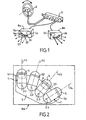
En se reportant à Fig. 1 des dessins, on peut voir une partie d'installation d'éclairage, sur véhicule automobile, qui comporte de chaque côté, à l'avant du véhicule, un projecteur lumineux fixe de virage Va situé à droite et Vb situé à gauche. Le projecteur de virage peut être logé dans le même boítier Ba, Bb que le projecteur code Ca, Cb correspondant. Chaque boítier est relié par un câble multiconducteur à une unité de commande U.Referring to Fig. 1 of the drawings, we can see some of the lighting installation, on a motor vehicle, which comprises of each side, at the front of the vehicle, a fixed luminous corner turn light located at right and Vb on the left. The turn projector can be housed in the same box Ba, Bb that the projector code Ca, Cb corresponding. Each housing is connected by a multicore cable to a control unit U.
Des moyens sensibles à la trajectoire du véhicule comprennent un capteur de volant E et fournissent à l'unité U un signal dépendant de la nature de la route suivie par le véhicule.Means sensitive to the trajectory of the vehicle include a steering wheel sensor E and provide the unit U with a signal dependent on the nature of the road followed by the vehicle.
Chaque projecteur fixe de virage Va, Vb comporte au moins deux et de préférence quatre sources lumineuses S1, S2, S3, S4 schématisées sur Fig. 2 pour le projecteur de virage Va.Each fixed cornering fixture Va, Vb comprises at least two and preferably four light sources S1, S2, S3, S4 schematized in FIG. 2 for the turn projector Va.
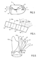
Chaque source lumineuse est avantageusement constituée par un
module 1 (Fig. 3) à diode électroluminescente 2. Les sources lumineuses
sont montées sur un support T logé dans le boítier Ba. Les modules S1-S4
sont montés avec une possibilité de réglage de leur orientation.Each light source is advantageously constituted by a
Module 1 (Fig. 3)
Chaque module 1 comporte un réflecteur 3 semi-ellipsoïdal d'axe
optique Y. Une LED 2 est située au foyer intérieur du réflecteur 3 et est
orientée de manière que l'axe de son faisceau lumineux soit orthogonal à
l'axe optique Y-Y. Le faisceau renvoyé par le réflecteur 3 tombe sur une
plaque 4 métallique réfléchissante, généralement appelée « plieuse », qui
peut être plane comme illustrée sur Fig. 3, ou pliée en forme de dièdre. La
plaque 4 est située au foyer externe du réflecteur 3, ou à son voisinage. Une
lentille convergente 5 est placée en sortie du module 1. Selon la forme de la
plieuse 4, le module 1 peut donner un faisceau à coupure plate ou à coupure
en V. Dans l'application considérée, le faisceau lumineux obtenu est de
préférence à coupure plate, la partie éclairée étant située au-dessous d'une
horizontale.Each
L'unité U est prévue pour commander un allumage progressif des sources S1-S4 en fonction du signal délivré par le capteur de volant E et assurer un effet de balayage lumineux avec défilement du faisceau lumineux et suivi du virage.Unit U is provided to control a progressive ignition of sources S1-S4 as a function of the signal delivered by the steering wheel sensor E and ensure a light-scanning effect with beam scrolling bright and follow the turn.
La source S1 située à gauche de l'ensemble éclaire moins que les autres vers la droite, c'est-à-dire vers l'intérieur d'un virage à droite. S1 est allumée en premier, puis la source S2, la source S3, la source S4. De préférence, la source précédente dans l'ordre d'allumage reste allumée lorsque la suivante est allumée.The source S1 located on the left of the set illuminates less than the others to the right, that is to say towards the interior of a right turn. S1 is first, then the source S2, the source S3, the source S4. Of preferably, the previous source in the firing order remains on when the next one is on.
Les axes optiques Y1, Y2, Y3, Y4 des modules S1-S4 sont orientés de plus en plus vers la droite, c'est-à-dire vers l'intérieur du virage à droite.The optical axes Y1, Y2, Y3, Y4 of the modules S1-S4 are oriented more and more to the right, that is towards the inside of the bend to the right.
Pour accroítre l'effet de balayage, l'ouverture angulaire des faisceaux lumineux fournis par les modules S1-S4 peut être croissante de S1 vers S4. L'angle d'ouverture du faisceau de S4 peut atteindre 40°.To increase the sweeping effect, the angular aperture of light beams provided by the S1-S4 modules can be growing from S1 to S4. The beam opening angle of S4 can reach 40 °.
En variante, comme illustré sur Fig. 4, les axes optiques Y1a-Y4a des modules sont parallèles entre eux mais inclinés vers la droite par rapport à l'axe longitudinal du véhicule. Dans ce cas, de préférence, l'ouverture angulaire des faisceaux augmente de S1 vers S4.Alternatively, as illustrated in FIG. 4, the optical axes Y1a-Y4a modules are parallel to each other but inclined to the right by relative to the longitudinal axis of the vehicle. In this case, preferably, the angular aperture of the beams increases from S1 to S4.
Fig.6 illustre un schéma de commande des diodes
électroluminescentes 2.1 à 2.4. Les anodes des diodes sont reliées en
parallèle à la borne + d'une source de tension continue 6 par exemple sous
12 V. Les cathodes des diodes sont reliées par l'intermédiaire d'une
résistance ballast 7.1 à 7.4 à une électrode d'un transistor de puissance
8.1 à 8.4 dont une autre électrode est reliée à la masse. L'électrode de
commande du transistor est reliée à une sortie de l'unité de commande U
dont une borne d'entrée reçoit le signal fourni par le capteur de volant E.Fig.6 illustrates a diode control scheme
electroluminescent 2.1 to 2.4. The anodes of the diodes are connected in
parallel to the + terminal of a
L'unité de commande U peut recevoir le signal d'information sur la trajectoire du véhicule à partir de moyens autres qu'un capteur de volant, par exemple à partir d'un navigateur GPS ou d'une caméra qui analyse la route en avant du véhicule, ou d' autres dispositifs équivalents.The control unit U can receive the information signal on the trajectory of the vehicle from means other than a steering wheel sensor, for example from a GPS navigator or a camera that analyzes the road in front of the vehicle, or other equivalent devices.
Les transistors de puissance 8.1 à 8.4 peuvent être commandés en tout ou rien comme illustré sur Fig.7 en deuxième et dernière ligne pour les LEDs 2.1 et 2.4. En variante, les transistors de puissance sont commandés en tension analogique ou modulée comme décrit ci-après au sujet des LEDs 2.2 et 2.3.The power transistors 8.1 to 8.4 can be controlled by all or nothing as shown in Fig.7 in the second and last line for LEDs 2.1 and 2.4. In a variant, the power transistors are controlled in analog or modulated voltage as described below about LEDs 2.2 and 2.3.
La première ligne de Fig.7 illustre la variation de l'angle de rotation du volant porté en ordonnée en fonction du temps t porté en abscisse, lorsque le véhicule effectue un virage. L'allumage de la première LED 2.1 est commandé lorsque l'angle de braquage atteint un premier seuil D1. La deuxième LED 2.2 est allumée lorsque l'angle de braquage atteint un deuxième seuil D2. Dans l'exemple de Fig. 7, l'allumage de la LED 2.2 est effectué selon une modulation linéaire analogique représentée par une rampe inclinée avant d'atteindre le niveau maximum.The first line of Fig.7 illustrates the variation of the angle of rotation of the steering wheel plotted on the ordinate as a function of time t abscissa, when the vehicle turns. The ignition of the first LED 2.1 is controlled when the steering angle reaches a first threshold D1. The second LED 2.2 is lit when the steering angle reaches a second threshold D2. In the example of FIG. 7, the lighting of the LED 2.2 is performed according to an analog linear modulation represented by a inclined ramp before reaching the maximum level.
La troisième LED 2.3 est allumée lorsque l'angle de braquage atteint un troisième seuil D3. Dans l'exemple de Fig. 7, l'allumage de cette LED s'effectue suivant une modulation par largeur d'impulsion (PWM). Les impulsions deviennent d'autant plus larges pour atteindre une valeur maximale correspondant à une alimentation permanente, selon l'augmentation de l'angle de braquage.The third LED 2.3 is on when the steering angle reaches a third threshold D3. In the example of FIG. 7, the ignition of this LED is carried out in pulse width modulation (PWM). The impulses become even wider to reach a value maximum corresponding to a permanent supply, according to increasing the steering angle.
La dernière LED 2.4 est allumée en tout ou rien lorsque l'angle de braquage atteint le seuil maximum D4.The last LED 2.4 is lit all or nothing when the angle turning speed reaches the maximum threshold D4.
Le schéma de Fig. 5 illustre le défilement du faisceau par modulation de chaque module à LED S1-S4.The scheme of FIG. 5 illustrates the beam scrolling through modulation of each S1-S4 LED module.
Les faisceaux principaux de croisement FCa, FCb sont représentés, les deux projecteurs codes étant allumés.The main crossing beams FCa, FCb are represented, the two code projectors being lit.
Lorsque le véhicule aborde un virage sur la droite, le module S1 est allumé en premier et produit un faisceau L1, par exemple d'axe parallèle à celui du véhicule. Puis, selon l'angle de braquage, les modules successifs S2, S3, S4 sont allumés, sans extinction des modules précédents, de sorte que l'on obtient des faisceaux L2, L3, L4 de plus en plus inclinés vers la droite, c'est-à-dire vers l'intérieur du virage.When the vehicle approaches a turn on the right, the S1 module is lit first and produces a beam L1, for example of parallel axis to that of the vehicle. Then, depending on the steering angle, the successive modules S2, S3, S4 are lit, without extinguishing the previous modules, so that we obtain beams L2, L3, L4 more and more inclined towards the right, that is, towards the inside of the turn.
Les sources lumineuses du projecteur fixe de virage situées sur la gauche restent éteintes lors d'un virage à droite,. Lors d'un virage à gauche, le projecteur fixe gauche de virage est allumé, alors que le projecteur fixe droit de virage reste éteint.The light sources of the fixed turn projector located on the left remain off when turning right ,. When turning left, the left turn stationary projector is on, while the fixed projector right of turn remains off.
L'allumage progressif des diodes électrolumi-nescentes 2.1-2.4, en fonction de l'angle du volant, donne un effet de balayage équivalent à une rotation de faisceau, sans pour autant mettre en oeuvre des pièces mécaniques en mouvement.Progressive ignition of the 2.1-2.4 light-emitting diodes, depending on the angle of the steering wheel, gives a sweeping effect equivalent to a beam rotation, without implementing parts mechanical movements.
Bien que le nombre de quatre sources lumineuses soit avantageux pour réaliser un effet de balayage spectaculaire, sans entraíner une augmentation trop forte du prix de revient, il est possible de réduire le coût en se limitant à deux sources lumineuses dont l'allumage successif crée déjà un effet de balayage.Although the number of four light sources is advantageous to achieve a dramatic sweeping effect, without causing a increase in the cost price, it is possible to reduce the cost by limiting itself to two light sources whose successive ignition already creates a sweeping effect.
Les diodes électroluminescentes permettent une modulation de l'intensité lumineuse sans glissement sensible de couleur de la lumière, contrairement à une lampe halogène modulée qui émet une lumière apparaissant de plus en plus blanche lorsque la tension d'alimentation augmente.Light-emitting diodes allow modulation of the luminous intensity without sensible slip of light color, unlike a modulated halogen lamp that emits a light appearing more and more white when the supply voltage increases.
Une telle lampe halogène, conjuguée avec une lampe à décharge produisant une lumière blanc bleuté, semble devenir rougeâtre lorsque sa tension d'alimentation augmente.Such a halogen lamp, combined with a discharge lamp producing a bluish white light, appears to become reddish when its supply voltage increases.
Claims (9)
caractérisé en ce que l'ouverture du faisceau lumineux des sources est de plus en plus grande vers l'intérieur du virage suivant l'ordre d'allumage des sources.Light projector according to one of the preceding claims,
characterized in that the opening of the source light beam is greater and greater towards the inside of the turn following the ignition order of the sources.
Priority Applications (3)
| Application Number | Priority Date | Filing Date | Title |
|---|---|---|---|
| DE602004010004T DE602004010004T3 (en) | 2003-07-24 | 2004-07-13 | Rigid curve headlights for motor vehicles |
| SI200430605T SI1500553T2 (en) | 2003-07-24 | 2004-07-13 | Fixed cornering headlamp for motor vehicles |
| PL04291793T PL1500553T5 (en) | 2003-07-24 | 2004-07-13 | Fixed cornering headlamp for motor vehicles |
Applications Claiming Priority (2)
| Application Number | Priority Date | Filing Date | Title |
|---|---|---|---|
| FR0309093 | 2003-07-24 | ||
| FR0309093A FR2857921B1 (en) | 2003-07-24 | 2003-07-24 | FIXED LIGHT PROJECTOR OF TURN FOR MOTOR VEHICLE |
Publications (3)
| Publication Number | Publication Date |
|---|---|
| EP1500553A1 true EP1500553A1 (en) | 2005-01-26 |
| EP1500553B1 EP1500553B1 (en) | 2007-11-14 |
| EP1500553B2 EP1500553B2 (en) | 2013-06-05 |
Family
ID=33484701
Family Applications (1)
| Application Number | Title | Priority Date | Filing Date |
|---|---|---|---|
| EP04291793.0A Active EP1500553B2 (en) | 2003-07-24 | 2004-07-13 | Fixed cornering headlamp for motor vehicles |
Country Status (9)
| Country | Link |
|---|---|
| US (2) | US7390112B2 (en) |
| EP (1) | EP1500553B2 (en) |
| JP (1) | JP4870341B2 (en) |
| AT (1) | ATE378217T1 (en) |
| DE (1) | DE602004010004T3 (en) |
| ES (1) | ES2297353T5 (en) |
| FR (1) | FR2857921B1 (en) |
| PL (1) | PL1500553T5 (en) |
| SI (1) | SI1500553T2 (en) |
Cited By (4)
| Publication number | Priority date | Publication date | Assignee | Title |
|---|---|---|---|---|
| US7237928B2 (en) | 2004-02-18 | 2007-07-03 | Koito Manufacturing Co., Ltd. | Vehicle head lamp |
| EP2019256A1 (en) | 2007-07-27 | 2009-01-28 | Valeo Vision | Lighting module for vehicle headlight |
| EP1502814B2 (en) † | 2003-08-01 | 2011-02-23 | Valeo Vision | Vehicle headlight with dipped beam light and cornering light |
| FR3022328A1 (en) * | 2014-06-16 | 2015-12-18 | Valeo Vision | ROTARY LIGHTING AND / OR SIGNALING MODULE |
Families Citing this family (23)
| Publication number | Priority date | Publication date | Assignee | Title |
|---|---|---|---|---|
| JP2008074327A (en) * | 2006-09-25 | 2008-04-03 | Mazda Motor Corp | Vehicular lighting system |
| US20080198617A1 (en) * | 2007-02-21 | 2008-08-21 | Gm Global Technology Operations, Inc. | LED Adaptive Forward Lighting Systems |
| JP4875519B2 (en) * | 2007-03-07 | 2012-02-15 | スタンレー電気株式会社 | Gaze guidance lighting device |
| FR2914886B1 (en) * | 2007-04-13 | 2010-02-26 | Valeo Vision | COMPACT LIGHTING DEVICE COMPRISING A TURN CODE FUNCTION. |
| CA2686226A1 (en) * | 2007-05-09 | 2008-11-20 | Magna International Inc. | Led headlamp with corner illumination |
| DE102007046339A1 (en) * | 2007-09-27 | 2009-04-02 | Osram Opto Semiconductors Gmbh | Light source with variable emission characteristics |
| US8585261B2 (en) * | 2008-04-25 | 2013-11-19 | Koninklijke Philips N.V. | Lamp assembly |
| EP2340186B1 (en) | 2008-10-20 | 2018-12-19 | Lumileds Holding B.V. | Led light |
| US10227033B2 (en) | 2010-03-19 | 2019-03-12 | Lumileds Llc | Lighting assembly for vehicle |
| JP6091757B2 (en) * | 2011-05-31 | 2017-03-08 | 株式会社小糸製作所 | Vehicle lamp control device |
| DE102011112716A1 (en) * | 2011-09-07 | 2013-03-07 | Audi Ag | Method for operating a headlamp of a motor vehicle |
| JP2013067343A (en) * | 2011-09-26 | 2013-04-18 | Koito Mfg Co Ltd | Light distribution control system for vehicle |
| KR20130129647A (en) * | 2012-05-21 | 2013-11-29 | 현대모비스 주식회사 | An automobile and method for controling thereof |
| KR101472966B1 (en) * | 2013-07-09 | 2014-12-16 | 에스엘 주식회사 | Automotive lamp |
| US9522628B2 (en) | 2014-05-20 | 2016-12-20 | Ford Global Technologies, Llc | Headlight assembly with static bending lights |
| USD762324S1 (en) | 2014-06-08 | 2016-07-26 | Valeo North America, Inc. | Stylized signature lamp |
| US10697607B2 (en) | 2014-06-08 | 2020-06-30 | Valeo North America, Inc. | Thin aspect lighting system with cutoff |
| DE202014004964U1 (en) | 2014-06-14 | 2015-09-15 | Automotive Lighting Reutlingen Gmbh | Headlight for motor vehicles |
| US9421904B2 (en) * | 2014-12-30 | 2016-08-23 | Chun-Hsien Kuo | Vehicle fog lamp set |
| US9855886B2 (en) | 2015-07-16 | 2018-01-02 | Honda Motor Co., Ltd. | Physical tire tracks coupled to headlights |
| JP2017109521A (en) * | 2015-12-14 | 2017-06-22 | 豊田合成株式会社 | Steering Wheel |
| US11079085B2 (en) * | 2018-07-23 | 2021-08-03 | Valeo North America, Inc. | Dynamic bending light module |
| FR3104235B1 (en) | 2019-12-09 | 2022-06-17 | Renault Sas | Method and system for controlling a dipped beam adaptive to bends configured to adapt the angle of activation of said light |
Citations (3)
| Publication number | Priority date | Publication date | Assignee | Title |
|---|---|---|---|---|
| GB178234A (en) * | 1921-01-26 | 1922-04-20 | Samuel Vernon Gramlich | Improvements in and relating to electric lighting systems for vehicles |
| DE19923187A1 (en) * | 1999-05-20 | 2000-11-23 | Daimler Chrysler Ag | Lighting system for motor vehicle for producing deflected light matching the travel situation including several lighting means arranged unmovable on vehicle longitudinal half |
| FR2811621A1 (en) * | 2000-07-11 | 2002-01-18 | Koito Mfg Co Ltd | Cornering lamp for irradiating a road surface ahead of and in an oblique direction of a motor vehicle while the vehicle is moving around a curve, has multiple bulbs each with reflector at selected angle for wide viewing area |
Family Cites Families (13)
| Publication number | Priority date | Publication date | Assignee | Title |
|---|---|---|---|---|
| DE19719573B4 (en) † | 1996-05-18 | 2006-08-17 | Volkswagen Ag | curve illumination |
| FR2760705B1 (en) | 1997-03-13 | 1999-05-28 | Valeo Vision | MOTOR VEHICLE LIGHTING SYSTEM COMPRISING AT LEAST TWO TURN HEADLIGHTS |
| DE19923198A1 (en) | 1998-07-29 | 2000-03-02 | Rieter Ag Maschf | Drawing unit for ring spinner has deflector between first two pairs of drawing rollers to eliminate slip-stick effects in sliver when spinning smooth yarns |
| DE19860461B4 (en) † | 1998-12-28 | 2012-09-27 | Automotive Lighting Reutlingen Gmbh | Headlamp system for vehicles for generating light bundles with different characteristics |
| US6367949B1 (en) † | 1999-08-04 | 2002-04-09 | 911 Emergency Products, Inc. | Par 36 LED utility lamp |
| DE19950135A1 (en) † | 1999-10-18 | 2001-04-19 | Patent Treuhand Ges Fuer Elektrische Gluehlampen Mbh | Control circuit for LED array has master string with given number of LEDs in string and control circuit also controls semiconducting switch of slave string |
| JP2001213227A (en) * | 2000-02-04 | 2001-08-07 | Koito Mfg Co Ltd | Lighting system for vehicle |
| JP2001283614A (en) * | 2000-03-31 | 2001-10-12 | Stanley Electric Co Ltd | Light guide tube, light guide tube device and lighting system for vehicle provided with the same |
| DE10017878A1 (en) † | 2000-04-11 | 2001-10-25 | Hella Kg Hueck & Co | Control device for a lamp of a motor vehicle provided with a number of light-emitting diodes |
| US6714128B2 (en) † | 2001-05-17 | 2004-03-30 | David C. Abbe | Motor vehicle lighting system |
| FR2839139B1 (en) * | 2002-04-25 | 2005-01-14 | Valeo Vision | LUMINAIRE-FREE ELLIPTICAL LIGHTING MODULE COMPRISING A CUT-OFF LIGHTING BEAM AND PROJECTOR COMPRISING SUCH A MODULE |
| FR2851029B1 (en) * | 2003-02-07 | 2006-01-13 | Valeo Vision | MOTOR VEHICLE PROJECTOR DEVICE EQUIPPED WITH ELECTROLUMINESCENT DIODES |
| US6953274B2 (en) * | 2003-05-30 | 2005-10-11 | Guide Corporation | AFS for LED headlamp |
-
2003
- 2003-07-24 FR FR0309093A patent/FR2857921B1/en not_active Expired - Fee Related
-
2004
- 2004-07-13 DE DE602004010004T patent/DE602004010004T3/en active Active
- 2004-07-13 EP EP04291793.0A patent/EP1500553B2/en active Active
- 2004-07-13 AT AT04291793T patent/ATE378217T1/en not_active IP Right Cessation
- 2004-07-13 SI SI200430605T patent/SI1500553T2/en unknown
- 2004-07-13 PL PL04291793T patent/PL1500553T5/en unknown
- 2004-07-13 ES ES04291793T patent/ES2297353T5/en active Active
- 2004-07-20 US US10/894,619 patent/US7390112B2/en active Active
- 2004-07-21 JP JP2004212592A patent/JP4870341B2/en not_active Expired - Fee Related
-
2008
- 2008-03-07 US US12/044,703 patent/US7699509B2/en not_active Expired - Fee Related
Patent Citations (3)
| Publication number | Priority date | Publication date | Assignee | Title |
|---|---|---|---|---|
| GB178234A (en) * | 1921-01-26 | 1922-04-20 | Samuel Vernon Gramlich | Improvements in and relating to electric lighting systems for vehicles |
| DE19923187A1 (en) * | 1999-05-20 | 2000-11-23 | Daimler Chrysler Ag | Lighting system for motor vehicle for producing deflected light matching the travel situation including several lighting means arranged unmovable on vehicle longitudinal half |
| FR2811621A1 (en) * | 2000-07-11 | 2002-01-18 | Koito Mfg Co Ltd | Cornering lamp for irradiating a road surface ahead of and in an oblique direction of a motor vehicle while the vehicle is moving around a curve, has multiple bulbs each with reflector at selected angle for wide viewing area |
Cited By (7)
| Publication number | Priority date | Publication date | Assignee | Title |
|---|---|---|---|---|
| EP1502814B2 (en) † | 2003-08-01 | 2011-02-23 | Valeo Vision | Vehicle headlight with dipped beam light and cornering light |
| US7237928B2 (en) | 2004-02-18 | 2007-07-03 | Koito Manufacturing Co., Ltd. | Vehicle head lamp |
| DE102005007626B4 (en) * | 2004-02-18 | 2012-10-25 | Koito Manufacturing Co., Ltd. | vehicle headlights |
| EP2019256A1 (en) | 2007-07-27 | 2009-01-28 | Valeo Vision | Lighting module for vehicle headlight |
| US7980742B2 (en) | 2007-07-27 | 2011-07-19 | Valeo Vision | Lighting module for a motor vehicle headlight |
| FR3022328A1 (en) * | 2014-06-16 | 2015-12-18 | Valeo Vision | ROTARY LIGHTING AND / OR SIGNALING MODULE |
| EP2957823A1 (en) * | 2014-06-16 | 2015-12-23 | Valeo Vision | Rotary lighting and/or signalling module |
Also Published As
| Publication number | Publication date |
|---|---|
| SI1500553T2 (en) | 2013-08-30 |
| JP4870341B2 (en) | 2012-02-08 |
| DE602004010004T2 (en) | 2008-09-18 |
| DE602004010004T3 (en) | 2013-10-31 |
| JP2005044805A (en) | 2005-02-17 |
| US20050018436A1 (en) | 2005-01-27 |
| ES2297353T5 (en) | 2013-07-18 |
| DE602004010004D1 (en) | 2007-12-27 |
| EP1500553B1 (en) | 2007-11-14 |
| SI1500553T1 (en) | 2008-04-30 |
| EP1500553B2 (en) | 2013-06-05 |
| US7390112B2 (en) | 2008-06-24 |
| ES2297353T3 (en) | 2008-05-01 |
| FR2857921A1 (en) | 2005-01-28 |
| FR2857921B1 (en) | 2006-11-24 |
| US7699509B2 (en) | 2010-04-20 |
| US20080151565A1 (en) | 2008-06-26 |
| PL1500553T5 (en) | 2013-10-31 |
| ATE378217T1 (en) | 2007-11-15 |
| PL1500553T3 (en) | 2008-04-30 |
Similar Documents
| Publication | Publication Date | Title |
|---|---|---|
| EP1500553B1 (en) | Fixed cornering headlamp for motor vehicles | |
| FR3026912B1 (en) | LAMP FOR VEHICLE AND ITS LIGHTING CIRCUIT | |
| EP1369639B1 (en) | Vehicle headlamp of the projection type comprising a secondary light source | |
| EP1449716B1 (en) | Lighting device for an automotive vehicle during cornering | |
| EP0864462A1 (en) | Lighting device for vehicle with two turn-headlamps | |
| FR2868508A1 (en) | LIGHT EMITTING DIODE HEADLIGHT FOR VEHICLE | |
| JP2003503253A (en) | Vehicle headlamps and vehicles | |
| US20130188374A1 (en) | Motor vehicle headlamp | |
| FR3040340A1 (en) | VEHICLE HEADLIGHT AND VEHICLE HEADLAMP SYSTEM | |
| EP2874468B1 (en) | Device for controlling a plurality of LED units, in particular for a motor vehicle | |
| EP2990264A2 (en) | Method for controlling a light beam and corresponding lighting and/or signalling module | |
| WO2016083689A1 (en) | Vehicle headlight | |
| EP1502814B1 (en) | Vehicle headlight with dipped beam light and cornering light | |
| FR2918323A1 (en) | Lamp for motor vehicle, has lighting circuit realizing control such that ratio between quantity of light from indicator lamp and quantity of light from dipped beam lamp is high when lamps are simultaneously illuminated | |
| FR3086033A1 (en) | LIGHT MODULE FOR MOTOR VEHICLE | |
| EP1241050B1 (en) | Arrangement of a lighting device in a vehicle | |
| EP1195295A1 (en) | Space saving lighting unit with modulated light intensity | |
| EP2093104A1 (en) | Power supply method for an automobile headlight and headlight implementing this method | |
| FR2957864A1 (en) | Method for controlling power supply of e.g. bi-functional headlamp of motor vehicle, involves allocating power supply mode of headlamp, and recording power supply mode associated with lighting modes | |
| FR3095494A1 (en) | Adaptive lighting device for vehicle headlight | |
| EP3436307B1 (en) | Vehicle headlamp | |
| WO2003093056A2 (en) | Signalling device for collision prevention | |
| FR3137155A1 (en) | Method for adapting the active lighting function of a motor vehicle depending on the driving context | |
| FR3115350A1 (en) | Headlight system and tilt vehicle | |
| FR2585304A1 (en) | Improvement to lighting systems for vehicles |
Legal Events
| Date | Code | Title | Description |
|---|---|---|---|
| PUAI | Public reference made under article 153(3) epc to a published international application that has entered the european phase |
Free format text: ORIGINAL CODE: 0009012 |
|
| AK | Designated contracting states |
Kind code of ref document: A1 Designated state(s): AT BE BG CH CY CZ DE DK EE ES FI FR GB GR HU IE IT LI LU MC NL PL PT RO SE SI SK TR |
|
| AX | Request for extension of the european patent |
Extension state: AL HR LT LV MK |
|
| 17P | Request for examination filed |
Effective date: 20050616 |
|
| AKX | Designation fees paid |
Designated state(s): AT BE BG CH CY CZ DE DK EE ES FI FR GB GR HU IE IT LI LU MC NL PL PT RO SE SI SK TR |
|
| GRAP | Despatch of communication of intention to grant a patent |
Free format text: ORIGINAL CODE: EPIDOSNIGR1 |
|
| RIN1 | Information on inventor provided before grant (corrected) |
Inventor name: LELEVE, JOEL |
|
| GRAS | Grant fee paid |
Free format text: ORIGINAL CODE: EPIDOSNIGR3 |
|
| GRAA | (expected) grant |
Free format text: ORIGINAL CODE: 0009210 |
|
| AK | Designated contracting states |
Kind code of ref document: B1 Designated state(s): AT BE BG CH CY CZ DE DK EE ES FI FR GB GR HU IE IT LI LU MC NL PL PT RO SE SI SK TR |
|
| REG | Reference to a national code |
Ref country code: GB Ref legal event code: FG4D Free format text: NOT ENGLISH |
|
| REG | Reference to a national code |
Ref country code: CH Ref legal event code: EP |
|
| REG | Reference to a national code |
Ref country code: IE Ref legal event code: FG4D Free format text: LANGUAGE OF EP DOCUMENT: FRENCH |
|
| REF | Corresponds to: |
Ref document number: 602004010004 Country of ref document: DE Date of ref document: 20071227 Kind code of ref document: P |
|
| PG25 | Lapsed in a contracting state [announced via postgrant information from national office to epo] |
Ref country code: NL Free format text: LAPSE BECAUSE OF FAILURE TO SUBMIT A TRANSLATION OF THE DESCRIPTION OR TO PAY THE FEE WITHIN THE PRESCRIBED TIME-LIMIT Effective date: 20071114 Ref country code: SE Free format text: LAPSE BECAUSE OF FAILURE TO SUBMIT A TRANSLATION OF THE DESCRIPTION OR TO PAY THE FEE WITHIN THE PRESCRIBED TIME-LIMIT Effective date: 20080214 |
|
| REG | Reference to a national code |
Ref country code: PL Ref legal event code: T3 |
|
| NLV1 | Nl: lapsed or annulled due to failure to fulfill the requirements of art. 29p and 29m of the patents act | ||
| REG | Reference to a national code |
Ref country code: ES Ref legal event code: FG2A Ref document number: 2297353 Country of ref document: ES Kind code of ref document: T3 |
|
| PG25 | Lapsed in a contracting state [announced via postgrant information from national office to epo] |
Ref country code: BG Free format text: LAPSE BECAUSE OF FAILURE TO SUBMIT A TRANSLATION OF THE DESCRIPTION OR TO PAY THE FEE WITHIN THE PRESCRIBED TIME-LIMIT Effective date: 20080214 Ref country code: FI Free format text: LAPSE BECAUSE OF FAILURE TO SUBMIT A TRANSLATION OF THE DESCRIPTION OR TO PAY THE FEE WITHIN THE PRESCRIBED TIME-LIMIT Effective date: 20071114 |
|
| GBV | Gb: ep patent (uk) treated as always having been void in accordance with gb section 77(7)/1977 [no translation filed] | ||
| PG25 | Lapsed in a contracting state [announced via postgrant information from national office to epo] |
Ref country code: AT Free format text: LAPSE BECAUSE OF FAILURE TO SUBMIT A TRANSLATION OF THE DESCRIPTION OR TO PAY THE FEE WITHIN THE PRESCRIBED TIME-LIMIT Effective date: 20071114 |
|
| PG25 | Lapsed in a contracting state [announced via postgrant information from national office to epo] |
Ref country code: DK Free format text: LAPSE BECAUSE OF FAILURE TO SUBMIT A TRANSLATION OF THE DESCRIPTION OR TO PAY THE FEE WITHIN THE PRESCRIBED TIME-LIMIT Effective date: 20071114 |
|
| PLBI | Opposition filed |
Free format text: ORIGINAL CODE: 0009260 |
|
| PG25 | Lapsed in a contracting state [announced via postgrant information from national office to epo] |
Ref country code: RO Free format text: LAPSE BECAUSE OF FAILURE TO SUBMIT A TRANSLATION OF THE DESCRIPTION OR TO PAY THE FEE WITHIN THE PRESCRIBED TIME-LIMIT Effective date: 20071114 |
|
| 26 | Opposition filed |
Opponent name: AUTOMOTIVE LIGHTING REUTLINGEN GMBH Effective date: 20080814 |
|
| PG25 | Lapsed in a contracting state [announced via postgrant information from national office to epo] |
Ref country code: PT Free format text: LAPSE BECAUSE OF FAILURE TO SUBMIT A TRANSLATION OF THE DESCRIPTION OR TO PAY THE FEE WITHIN THE PRESCRIBED TIME-LIMIT Effective date: 20080414 |
|
| REG | Reference to a national code |
Ref country code: IE Ref legal event code: FD4D |
|
| PLAX | Notice of opposition and request to file observation + time limit sent |
Free format text: ORIGINAL CODE: EPIDOSNOBS2 |
|
| PG25 | Lapsed in a contracting state [announced via postgrant information from national office to epo] |
Ref country code: IE Free format text: LAPSE BECAUSE OF FAILURE TO SUBMIT A TRANSLATION OF THE DESCRIPTION OR TO PAY THE FEE WITHIN THE PRESCRIBED TIME-LIMIT Effective date: 20071114 |
|
| PG25 | Lapsed in a contracting state [announced via postgrant information from national office to epo] |
Ref country code: GB Free format text: LAPSE BECAUSE OF FAILURE TO SUBMIT A TRANSLATION OF THE DESCRIPTION OR TO PAY THE FEE WITHIN THE PRESCRIBED TIME-LIMIT Effective date: 20071114 |
|
| PLAF | Information modified related to communication of a notice of opposition and request to file observations + time limit |
Free format text: ORIGINAL CODE: EPIDOSCOBS2 |
|
| PG25 | Lapsed in a contracting state [announced via postgrant information from national office to epo] |
Ref country code: GR Free format text: LAPSE BECAUSE OF FAILURE TO SUBMIT A TRANSLATION OF THE DESCRIPTION OR TO PAY THE FEE WITHIN THE PRESCRIBED TIME-LIMIT Effective date: 20080215 |
|
| REG | Reference to a national code |
Ref country code: CH Ref legal event code: PL |
|
| PLBB | Reply of patent proprietor to notice(s) of opposition received |
Free format text: ORIGINAL CODE: EPIDOSNOBS3 |
|
| PG25 | Lapsed in a contracting state [announced via postgrant information from national office to epo] |
Ref country code: MC Free format text: LAPSE BECAUSE OF NON-PAYMENT OF DUE FEES Effective date: 20080731 |
|
| PG25 | Lapsed in a contracting state [announced via postgrant information from national office to epo] |
Ref country code: EE Free format text: LAPSE BECAUSE OF FAILURE TO SUBMIT A TRANSLATION OF THE DESCRIPTION OR TO PAY THE FEE WITHIN THE PRESCRIBED TIME-LIMIT Effective date: 20071114 |
|
| PG25 | Lapsed in a contracting state [announced via postgrant information from national office to epo] |
Ref country code: CH Free format text: LAPSE BECAUSE OF NON-PAYMENT OF DUE FEES Effective date: 20080731 Ref country code: LI Free format text: LAPSE BECAUSE OF NON-PAYMENT OF DUE FEES Effective date: 20080731 |
|
| PG25 | Lapsed in a contracting state [announced via postgrant information from national office to epo] |
Ref country code: CY Free format text: LAPSE BECAUSE OF FAILURE TO SUBMIT A TRANSLATION OF THE DESCRIPTION OR TO PAY THE FEE WITHIN THE PRESCRIBED TIME-LIMIT Effective date: 20071114 |
|
| RDAF | Communication despatched that patent is revoked |
Free format text: ORIGINAL CODE: EPIDOSNREV1 |
|
| APBM | Appeal reference recorded |
Free format text: ORIGINAL CODE: EPIDOSNREFNO |
|
| APBP | Date of receipt of notice of appeal recorded |
Free format text: ORIGINAL CODE: EPIDOSNNOA2O |
|
| APAH | Appeal reference modified |
Free format text: ORIGINAL CODE: EPIDOSCREFNO |
|
| APBQ | Date of receipt of statement of grounds of appeal recorded |
Free format text: ORIGINAL CODE: EPIDOSNNOA3O |
|
| PG25 | Lapsed in a contracting state [announced via postgrant information from national office to epo] |
Ref country code: BE Free format text: LAPSE BECAUSE OF NON-PAYMENT OF DUE FEES Effective date: 20080731 Ref country code: HU Free format text: LAPSE BECAUSE OF FAILURE TO SUBMIT A TRANSLATION OF THE DESCRIPTION OR TO PAY THE FEE WITHIN THE PRESCRIBED TIME-LIMIT Effective date: 20080515 Ref country code: LU Free format text: LAPSE BECAUSE OF NON-PAYMENT OF DUE FEES Effective date: 20080713 |
|
| PG25 | Lapsed in a contracting state [announced via postgrant information from national office to epo] |
Ref country code: TR Free format text: LAPSE BECAUSE OF FAILURE TO SUBMIT A TRANSLATION OF THE DESCRIPTION OR TO PAY THE FEE WITHIN THE PRESCRIBED TIME-LIMIT Effective date: 20071114 |
|
| APBU | Appeal procedure closed |
Free format text: ORIGINAL CODE: EPIDOSNNOA9O |
|
| PUAH | Patent maintained in amended form |
Free format text: ORIGINAL CODE: 0009272 |
|
| STAA | Information on the status of an ep patent application or granted ep patent |
Free format text: STATUS: PATENT MAINTAINED AS AMENDED |
|
| 27A | Patent maintained in amended form |
Effective date: 20130605 |
|
| AK | Designated contracting states |
Kind code of ref document: B2 Designated state(s): AT BE BG CH CY CZ DE DK EE ES FI FR GB GR HU IE IT LI LU MC NL PL PT RO SE SI SK TR |
|
| REG | Reference to a national code |
Ref country code: ES Ref legal event code: DC2A Ref document number: 2297353 Country of ref document: ES Kind code of ref document: T5 Effective date: 20130718 |
|
| REG | Reference to a national code |
Ref country code: DE Ref legal event code: R102 Ref document number: 602004010004 Country of ref document: DE Effective date: 20130605 |
|
| REG | Reference to a national code |
Ref country code: PL Ref legal event code: T5 |
|
| REG | Reference to a national code |
Ref country code: SK Ref legal event code: T5 Ref document number: E 3050 Country of ref document: SK |
|
| REG | Reference to a national code |
Ref country code: FR Ref legal event code: PLFP Year of fee payment: 13 |
|
| REG | Reference to a national code |
Ref country code: FR Ref legal event code: PLFP Year of fee payment: 14 |
|
| REG | Reference to a national code |
Ref country code: FR Ref legal event code: PLFP Year of fee payment: 15 |
|
| PGFP | Annual fee paid to national office [announced via postgrant information from national office to epo] |
Ref country code: SK Payment date: 20180618 Year of fee payment: 15 |
|
| PGFP | Annual fee paid to national office [announced via postgrant information from national office to epo] |
Ref country code: PL Payment date: 20180619 Year of fee payment: 15 |
|
| PGFP | Annual fee paid to national office [announced via postgrant information from national office to epo] |
Ref country code: SI Payment date: 20180620 Year of fee payment: 15 |
|
| REG | Reference to a national code |
Ref country code: SK Ref legal event code: MM4A Ref document number: E 3050 Country of ref document: SK Effective date: 20190713 |
|
| REG | Reference to a national code |
Ref country code: SI Ref legal event code: KO00 Effective date: 20200310 |
|
| PG25 | Lapsed in a contracting state [announced via postgrant information from national office to epo] |
Ref country code: SI Free format text: LAPSE BECAUSE OF NON-PAYMENT OF DUE FEES Effective date: 20190714 Ref country code: SK Free format text: LAPSE BECAUSE OF NON-PAYMENT OF DUE FEES Effective date: 20190713 |
|
| PGFP | Annual fee paid to national office [announced via postgrant information from national office to epo] |
Ref country code: CZ Payment date: 20200617 Year of fee payment: 17 |
|
| PGFP | Annual fee paid to national office [announced via postgrant information from national office to epo] |
Ref country code: ES Payment date: 20200817 Year of fee payment: 17 |
|
| PGFP | Annual fee paid to national office [announced via postgrant information from national office to epo] |
Ref country code: IT Payment date: 20200713 Year of fee payment: 17 |
|
| PG25 | Lapsed in a contracting state [announced via postgrant information from national office to epo] |
Ref country code: PL Free format text: LAPSE BECAUSE OF NON-PAYMENT OF DUE FEES Effective date: 20190713 |
|
| PG25 | Lapsed in a contracting state [announced via postgrant information from national office to epo] |
Ref country code: CZ Free format text: LAPSE BECAUSE OF NON-PAYMENT OF DUE FEES Effective date: 20210713 |
|
| PG25 | Lapsed in a contracting state [announced via postgrant information from national office to epo] |
Ref country code: IT Free format text: LAPSE BECAUSE OF NON-PAYMENT OF DUE FEES Effective date: 20210713 |
|
| REG | Reference to a national code |
Ref country code: ES Ref legal event code: FD2A Effective date: 20220826 |
|
| PG25 | Lapsed in a contracting state [announced via postgrant information from national office to epo] |
Ref country code: ES Free format text: LAPSE BECAUSE OF NON-PAYMENT OF DUE FEES Effective date: 20210714 |
|
| PGFP | Annual fee paid to national office [announced via postgrant information from national office to epo] |
Ref country code: DE Payment date: 20220624 Year of fee payment: 19 |
|
| PGFP | Annual fee paid to national office [announced via postgrant information from national office to epo] |
Ref country code: FR Payment date: 20220726 Year of fee payment: 19 |
|
| P01 | Opt-out of the competence of the unified patent court (upc) registered |
Effective date: 20230528 |
|
| REG | Reference to a national code |
Ref country code: DE Ref legal event code: R119 Ref document number: 602004010004 Country of ref document: DE |