EP1500935A1 - Analytical instrument - Google Patents
Analytical instrument Download PDFInfo
- Publication number
- EP1500935A1 EP1500935A1 EP03720977A EP03720977A EP1500935A1 EP 1500935 A1 EP1500935 A1 EP 1500935A1 EP 03720977 A EP03720977 A EP 03720977A EP 03720977 A EP03720977 A EP 03720977A EP 1500935 A1 EP1500935 A1 EP 1500935A1
- Authority
- EP
- European Patent Office
- Prior art keywords
- analytical instrument
- capillary
- members
- instrument according
- groove
- Prior art date
- Legal status (The legal status is an assumption and is not a legal conclusion. Google has not performed a legal analysis and makes no representation as to the accuracy of the status listed.)
- Withdrawn
Links
- 229920001971 elastomer Polymers 0.000 claims abstract description 21
- 239000000806 elastomer Substances 0.000 claims abstract description 21
- 239000003153 chemical reaction reagent Substances 0.000 claims description 19
- 230000001464 adherent effect Effects 0.000 claims description 12
- 239000000463 material Substances 0.000 claims description 5
- 238000007789 sealing Methods 0.000 abstract description 6
- 239000000758 substrate Substances 0.000 description 62
- 239000000853 adhesive Substances 0.000 description 21
- 230000001070 adhesive effect Effects 0.000 description 21
- 125000006850 spacer group Chemical group 0.000 description 15
- 239000007788 liquid Substances 0.000 description 6
- 229920003002 synthetic resin Polymers 0.000 description 6
- 239000000057 synthetic resin Substances 0.000 description 6
- 238000005259 measurement Methods 0.000 description 5
- 239000011521 glass Substances 0.000 description 4
- 239000000126 substance Substances 0.000 description 4
- 238000004519 manufacturing process Methods 0.000 description 3
- 230000002411 adverse Effects 0.000 description 2
- 230000003287 optical effect Effects 0.000 description 2
- 229920001296 polysiloxane Polymers 0.000 description 2
- 229920000181 Ethylene propylene rubber Polymers 0.000 description 1
- WQZGKKKJIJFFOK-GASJEMHNSA-N Glucose Natural products OC[C@H]1OC(O)[C@H](O)[C@@H](O)[C@@H]1O WQZGKKKJIJFFOK-GASJEMHNSA-N 0.000 description 1
- 229920001328 Polyvinylidene chloride Polymers 0.000 description 1
- WYTGDNHDOZPMIW-RCBQFDQVSA-N alstonine Natural products C1=CC2=C3C=CC=CC3=NC2=C2N1C[C@H]1[C@H](C)OC=C(C(=O)OC)[C@H]1C2 WYTGDNHDOZPMIW-RCBQFDQVSA-N 0.000 description 1
- 230000015572 biosynthetic process Effects 0.000 description 1
- 239000008280 blood Substances 0.000 description 1
- 210000004369 blood Anatomy 0.000 description 1
- 210000001124 body fluid Anatomy 0.000 description 1
- 239000010839 body fluid Substances 0.000 description 1
- 230000003247 decreasing effect Effects 0.000 description 1
- 238000007599 discharging Methods 0.000 description 1
- 230000004927 fusion Effects 0.000 description 1
- 239000008103 glucose Substances 0.000 description 1
- 238000010438 heat treatment Methods 0.000 description 1
- 238000010030 laminating Methods 0.000 description 1
- 239000000203 mixture Substances 0.000 description 1
- 230000000149 penetrating effect Effects 0.000 description 1
- 239000005033 polyvinylidene chloride Substances 0.000 description 1
- 235000019353 potassium silicate Nutrition 0.000 description 1
- 230000001737 promoting effect Effects 0.000 description 1
- 229920005989 resin Polymers 0.000 description 1
- 239000011347 resin Substances 0.000 description 1
- 238000000926 separation method Methods 0.000 description 1
- 229920002379 silicone rubber Polymers 0.000 description 1
- 239000004945 silicone rubber Substances 0.000 description 1
Images


Classifications
-
- B—PERFORMING OPERATIONS; TRANSPORTING
- B01—PHYSICAL OR CHEMICAL PROCESSES OR APPARATUS IN GENERAL
- B01L—CHEMICAL OR PHYSICAL LABORATORY APPARATUS FOR GENERAL USE
- B01L3/00—Containers or dishes for laboratory use, e.g. laboratory glassware; Droppers
- B01L3/50—Containers for the purpose of retaining a material to be analysed, e.g. test tubes
- B01L3/502—Containers for the purpose of retaining a material to be analysed, e.g. test tubes with fluid transport, e.g. in multi-compartment structures
- B01L3/5027—Containers for the purpose of retaining a material to be analysed, e.g. test tubes with fluid transport, e.g. in multi-compartment structures by integrated microfluidic structures, i.e. dimensions of channels and chambers are such that surface tension forces are important, e.g. lab-on-a-chip
- B01L3/502707—Containers for the purpose of retaining a material to be analysed, e.g. test tubes with fluid transport, e.g. in multi-compartment structures by integrated microfluidic structures, i.e. dimensions of channels and chambers are such that surface tension forces are important, e.g. lab-on-a-chip characterised by the manufacture of the container or its components
-
- B—PERFORMING OPERATIONS; TRANSPORTING
- B29—WORKING OF PLASTICS; WORKING OF SUBSTANCES IN A PLASTIC STATE IN GENERAL
- B29C—SHAPING OR JOINING OF PLASTICS; SHAPING OF MATERIAL IN A PLASTIC STATE, NOT OTHERWISE PROVIDED FOR; AFTER-TREATMENT OF THE SHAPED PRODUCTS, e.g. REPAIRING
- B29C65/00—Joining or sealing of preformed parts, e.g. welding of plastics materials; Apparatus therefor
- B29C65/002—Joining methods not otherwise provided for
-
- B—PERFORMING OPERATIONS; TRANSPORTING
- B29—WORKING OF PLASTICS; WORKING OF SUBSTANCES IN A PLASTIC STATE IN GENERAL
- B29C—SHAPING OR JOINING OF PLASTICS; SHAPING OF MATERIAL IN A PLASTIC STATE, NOT OTHERWISE PROVIDED FOR; AFTER-TREATMENT OF THE SHAPED PRODUCTS, e.g. REPAIRING
- B29C66/00—General aspects of processes or apparatus for joining preformed parts
- B29C66/01—General aspects dealing with the joint area or with the area to be joined
- B29C66/05—Particular design of joint configurations
- B29C66/10—Particular design of joint configurations particular design of the joint cross-sections
- B29C66/11—Joint cross-sections comprising a single joint-segment, i.e. one of the parts to be joined comprising a single joint-segment in the joint cross-section
- B29C66/112—Single lapped joints
- B29C66/1122—Single lap to lap joints, i.e. overlap joints
-
- B—PERFORMING OPERATIONS; TRANSPORTING
- B29—WORKING OF PLASTICS; WORKING OF SUBSTANCES IN A PLASTIC STATE IN GENERAL
- B29C—SHAPING OR JOINING OF PLASTICS; SHAPING OF MATERIAL IN A PLASTIC STATE, NOT OTHERWISE PROVIDED FOR; AFTER-TREATMENT OF THE SHAPED PRODUCTS, e.g. REPAIRING
- B29C66/00—General aspects of processes or apparatus for joining preformed parts
- B29C66/50—General aspects of joining tubular articles; General aspects of joining long products, i.e. bars or profiled elements; General aspects of joining single elements to tubular articles, hollow articles or bars; General aspects of joining several hollow-preforms to form hollow or tubular articles
- B29C66/51—Joining tubular articles, profiled elements or bars; Joining single elements to tubular articles, hollow articles or bars; Joining several hollow-preforms to form hollow or tubular articles
- B29C66/53—Joining single elements to tubular articles, hollow articles or bars
- B29C66/534—Joining single elements to open ends of tubular or hollow articles or to the ends of bars
- B29C66/5346—Joining single elements to open ends of tubular or hollow articles or to the ends of bars said single elements being substantially flat
- B29C66/53461—Joining single elements to open ends of tubular or hollow articles or to the ends of bars said single elements being substantially flat joining substantially flat covers and/or substantially flat bottoms to open ends of container bodies
- B29C66/53462—Joining single elements to open ends of tubular or hollow articles or to the ends of bars said single elements being substantially flat joining substantially flat covers and/or substantially flat bottoms to open ends of container bodies joining substantially flat covers and substantially flat bottoms to open ends of container bodies
-
- B—PERFORMING OPERATIONS; TRANSPORTING
- B29—WORKING OF PLASTICS; WORKING OF SUBSTANCES IN A PLASTIC STATE IN GENERAL
- B29C—SHAPING OR JOINING OF PLASTICS; SHAPING OF MATERIAL IN A PLASTIC STATE, NOT OTHERWISE PROVIDED FOR; AFTER-TREATMENT OF THE SHAPED PRODUCTS, e.g. REPAIRING
- B29C66/00—General aspects of processes or apparatus for joining preformed parts
- B29C66/50—General aspects of joining tubular articles; General aspects of joining long products, i.e. bars or profiled elements; General aspects of joining single elements to tubular articles, hollow articles or bars; General aspects of joining several hollow-preforms to form hollow or tubular articles
- B29C66/51—Joining tubular articles, profiled elements or bars; Joining single elements to tubular articles, hollow articles or bars; Joining several hollow-preforms to form hollow or tubular articles
- B29C66/54—Joining several hollow-preforms, e.g. half-shells, to form hollow articles, e.g. for making balls, containers; Joining several hollow-preforms, e.g. half-cylinders, to form tubular articles
- B29C66/542—Joining several hollow-preforms, e.g. half-shells, to form hollow articles, e.g. for making balls, containers; Joining several hollow-preforms, e.g. half-cylinders, to form tubular articles joining hollow covers or hollow bottoms to open ends of container bodies
-
- G—PHYSICS
- G01—MEASURING; TESTING
- G01N—INVESTIGATING OR ANALYSING MATERIALS BY DETERMINING THEIR CHEMICAL OR PHYSICAL PROPERTIES
- G01N27/00—Investigating or analysing materials by the use of electric, electrochemical, or magnetic means
- G01N27/26—Investigating or analysing materials by the use of electric, electrochemical, or magnetic means by investigating electrochemical variables; by using electrolysis or electrophoresis
- G01N27/416—Systems
- G01N27/447—Systems using electrophoresis
- G01N27/44756—Apparatus specially adapted therefor
- G01N27/44782—Apparatus specially adapted therefor of a plurality of samples
-
- G—PHYSICS
- G01—MEASURING; TESTING
- G01N—INVESTIGATING OR ANALYSING MATERIALS BY DETERMINING THEIR CHEMICAL OR PHYSICAL PROPERTIES
- G01N35/00—Automatic analysis not limited to methods or materials provided for in any single one of groups G01N1/00 - G01N33/00; Handling materials therefor
- G01N35/00029—Automatic analysis not limited to methods or materials provided for in any single one of groups G01N1/00 - G01N33/00; Handling materials therefor provided with flat sample substrates, e.g. slides
-
- B—PERFORMING OPERATIONS; TRANSPORTING
- B01—PHYSICAL OR CHEMICAL PROCESSES OR APPARATUS IN GENERAL
- B01L—CHEMICAL OR PHYSICAL LABORATORY APPARATUS FOR GENERAL USE
- B01L2200/00—Solutions for specific problems relating to chemical or physical laboratory apparatus
- B01L2200/06—Fluid handling related problems
- B01L2200/0689—Sealing
-
- B—PERFORMING OPERATIONS; TRANSPORTING
- B01—PHYSICAL OR CHEMICAL PROCESSES OR APPARATUS IN GENERAL
- B01L—CHEMICAL OR PHYSICAL LABORATORY APPARATUS FOR GENERAL USE
- B01L2200/00—Solutions for specific problems relating to chemical or physical laboratory apparatus
- B01L2200/12—Specific details about manufacturing devices
-
- B—PERFORMING OPERATIONS; TRANSPORTING
- B01—PHYSICAL OR CHEMICAL PROCESSES OR APPARATUS IN GENERAL
- B01L—CHEMICAL OR PHYSICAL LABORATORY APPARATUS FOR GENERAL USE
- B01L2300/00—Additional constructional details
- B01L2300/06—Auxiliary integrated devices, integrated components
- B01L2300/0627—Sensor or part of a sensor is integrated
- B01L2300/0645—Electrodes
-
- B—PERFORMING OPERATIONS; TRANSPORTING
- B01—PHYSICAL OR CHEMICAL PROCESSES OR APPARATUS IN GENERAL
- B01L—CHEMICAL OR PHYSICAL LABORATORY APPARATUS FOR GENERAL USE
- B01L2300/00—Additional constructional details
- B01L2300/08—Geometry, shape and general structure
- B01L2300/0809—Geometry, shape and general structure rectangular shaped
- B01L2300/0816—Cards, e.g. flat sample carriers usually with flow in two horizontal directions
-
- B—PERFORMING OPERATIONS; TRANSPORTING
- B01—PHYSICAL OR CHEMICAL PROCESSES OR APPARATUS IN GENERAL
- B01L—CHEMICAL OR PHYSICAL LABORATORY APPARATUS FOR GENERAL USE
- B01L2300/00—Additional constructional details
- B01L2300/08—Geometry, shape and general structure
- B01L2300/0861—Configuration of multiple channels and/or chambers in a single devices
- B01L2300/0867—Multiple inlets and one sample wells, e.g. mixing, dilution
-
- B—PERFORMING OPERATIONS; TRANSPORTING
- B01—PHYSICAL OR CHEMICAL PROCESSES OR APPARATUS IN GENERAL
- B01L—CHEMICAL OR PHYSICAL LABORATORY APPARATUS FOR GENERAL USE
- B01L2300/00—Additional constructional details
- B01L2300/08—Geometry, shape and general structure
- B01L2300/0887—Laminated structure
-
- B—PERFORMING OPERATIONS; TRANSPORTING
- B29—WORKING OF PLASTICS; WORKING OF SUBSTANCES IN A PLASTIC STATE IN GENERAL
- B29C—SHAPING OR JOINING OF PLASTICS; SHAPING OF MATERIAL IN A PLASTIC STATE, NOT OTHERWISE PROVIDED FOR; AFTER-TREATMENT OF THE SHAPED PRODUCTS, e.g. REPAIRING
- B29C66/00—General aspects of processes or apparatus for joining preformed parts
- B29C66/70—General aspects of processes or apparatus for joining preformed parts characterised by the composition, physical properties or the structure of the material of the parts to be joined; Joining with non-plastics material
- B29C66/71—General aspects of processes or apparatus for joining preformed parts characterised by the composition, physical properties or the structure of the material of the parts to be joined; Joining with non-plastics material characterised by the composition of the plastics material of the parts to be joined
-
- B—PERFORMING OPERATIONS; TRANSPORTING
- B29—WORKING OF PLASTICS; WORKING OF SUBSTANCES IN A PLASTIC STATE IN GENERAL
- B29K—INDEXING SCHEME ASSOCIATED WITH SUBCLASSES B29B, B29C OR B29D, RELATING TO MOULDING MATERIALS OR TO MATERIALS FOR MOULDS, REINFORCEMENTS, FILLERS OR PREFORMED PARTS, e.g. INSERTS
- B29K2021/00—Use of unspecified rubbers as moulding material
-
- B—PERFORMING OPERATIONS; TRANSPORTING
- B29—WORKING OF PLASTICS; WORKING OF SUBSTANCES IN A PLASTIC STATE IN GENERAL
- B29L—INDEXING SCHEME ASSOCIATED WITH SUBCLASS B29C, RELATING TO PARTICULAR ARTICLES
- B29L2031/00—Other particular articles
- B29L2031/756—Microarticles, nanoarticles
-
- G—PHYSICS
- G01—MEASURING; TESTING
- G01N—INVESTIGATING OR ANALYSING MATERIALS BY DETERMINING THEIR CHEMICAL OR PHYSICAL PROPERTIES
- G01N35/00—Automatic analysis not limited to methods or materials provided for in any single one of groups G01N1/00 - G01N33/00; Handling materials therefor
- G01N2035/00178—Special arrangements of analysers
- G01N2035/00237—Handling microquantities of analyte, e.g. microvalves, capillary networks
Definitions
- the present invention relates to an analytical instrument used for analyzing a sample in a liquid state such as a body fluid.
- Figs. 11A and 11B show an example of prior art analytical instrument.
- the analytical instrument includes a substrate 90 and a cover 91 stacked and bonded together to define a capillary 92.
- the capillary 92 is defined by closing an upper opening of a groove 92a formed at an upper surface of the substrate 90 by the cover 91.
- the sample when a sample in a liquid state is supplied to a sample introduction port 93 formed in the cover 91, the sample travels through the capillary 92 in a direction indicated by the arrow Na by capillary action. While the sample travels through the capillary 92, the sample may be mixed with a reagent for causing a predetermined reaction or subjected to component separation, whereby the sample is analyzed.
- the substrate 90 and the cover 91 have sometimes been made of glass or silicone.
- the substrate 90 and the cover 91 can be reliably bonded together by water glass bonding or anode bonding, for example.
- the working of glass or silicone is not easy, the cost for manufacturing the analytical instrument disadvantageously increases.
- the substrate 90 and the cover 91 are often made of a synthetic resin for decreasing the cost for the parts.
- the substrate 90 and the cover 91 are often bonded together with an adhesive or by fusing utilizing ultrasonic wave.
- the vertical dimension H of the capillary 92 (the dimension in the thickness direction of the analytical instrument) becomes the total dimension of the depth h1 of the groove 92a and the thickness h2 of the adhesive 80.
- a projection in the form of a rib (not shown) is formed at a bonding surface, and ultrasonic wave is applied to the projection to heat and deform the projection.
- the portion to be deformed vibrates at an amplitude of about 10 ⁇ m. Due to such vibration, the degree of deformation of the projection cannot be kept constant, so that the capillary 92 of an intended size may not be formed.
- the size of the capillary 92 differs from an intended, proper one, conditions such as the travel speed or amount of the sample which flows through the capillary 92 may differ from the intended conditions, which may cause inaccurate analysis results.
- the manufacturing of the analytical instrument is difficult when the configuration of the capillary 92 is complicated.
- the groove 92a need be avoided so that the adhesive 80 does not enter the groove 92a. Therefore, when the configuration of the capillary 92 is complicated, the application of the adhesive following the configuration is troublesome and difficult.
- the projection for fusing need be formed correspondingly to the configuration of the capillary 92. Therefore, in such a case again, the work is troublesome when the configuration of the capillary 92 is complicated.
- the sealing performance around the capillary 92 is not good.
- the portion forms a gap communicating with the capillary 92, causing a fear that the sample may unduly enter the portion.
- ultrasonic wave is utilized.
- these members are sometimes warped to reduce the flatness at the bonding surfaces. In such a case, the sealing performance around the capillary 92 is further deteriorated.
- An object of the present invention is to provide an analytical instrument capable of solving or lessening the above-described problems.
- an analytical instrument comprising a first and a second members stacked on each other, and a capillary defined by covering an opening of a groove formed in one of the first and the second members with the other of the first and the second members.
- the first member includes a bonding surface made of self-adherent elastomer, and the first and second members are bonded together via the bonding surface.
- the first member comprises a non-adherent base member and a sheet of self-adherent elastomer bonded to the base member, and the bonding surface comprises one surface of the sheet.
- the first member is entirely made of self-adherent elastomer.
- the second member is made of a non-adherent material, and the groove is formed in the second member.
- the second member comprises a plate or sheet having one surface at which the groove is formed as a bottomed groove, and the first member is bonded to the one surface of the second member.
- the capillary has one end branching into a plurality of paths, and the paths are formed with a sample receiving portion and a reagent receiving portion connected thereto.
- the capillary has another end formed with a reaction portion connected thereto for causing reaction between a sample and a reagent.
- the analytical instrument according to the present invention includes a plurality of second members, and the first member comprises a plate or sheet in which the groove is formed to penetrate thicknesswise and which has an obverse surface and a reverse surface each serving as the bonding surface.
- the plurality of second members are bonded to the obverse surface and the reverse surface of the first member.
- the analytical instrument according to the present invention includes a plurality of first members, and the second member comprises a plate or sheet in which the groove is formed to penetrate thicknesswise.
- the second member has an obverse and a reverse surfaces to which the first members are bonded.
- the capillary has one end serving as a sample introduction port and includes a reaction portion containing a reagent.
- an analytical instrument comprising a first and a second members stacked on each other, and a capillary defined by causing the second member to cover an opening of a groove formed in the first member.
- the second member is made of elastomer, and the analytical instrument further includes a third member for pressing the second member against the first member.
- the second member is sandwiched between the first and the third members, and the third member is partially bonded to the first member at an outer periphery of the second member.
- the third member includes a projection for engaging the first member at an outer periphery of the second member, and respective engaging portions of the projection and the first member are bonded together.
- the third member comprises a flexible plate or sheet, and the third member being flexibly deformed so that an outer periphery of the third member comes into contact with the first member. Respective contacting portions of the third member and the first member are bonded together.
- Figs. 1-3 show an embodiment of analytical instrument according to the present invention.
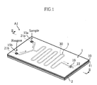
- the analytical instrument A1 of this embodiment includes a cover 1, a substrate 2 and a capillary 3 provided between the cover and the substrate.
- the cover 1 and the substrate 2 are examples of a first and a second members of the present invention.
- the cover 1 comprises a flexible rectangular plate or sheet formed by laminating a sheet 11 made of a self-adherent elastomer on a base member 10.
- the sheet 11 may be made of silicone rubber.
- the material is not limited to a specific one, and other self-adherent elastomer may be used. However, it is preferable to use an elastomer that does not adversely affect the analysis results of the sample upon contact with the sample.
- the sheet 11 has opposite surfaces both of which are adherent and is bonded to the base member 10 by utilizing the adhesion of one of the opposite surfaces. The other one of the opposite surfaces serves as a bonding surface 11a for bonding the cover 1 to the substrate 2.
- the base member 10 is made of a non-adherent synthetic resin.
- the substrate 2 comprises a plate or sheet having a rectangular configuration similar to that of the cover 1 and made of a non-adherent synthetic resin.
- the substrate 2 has an upper surface formed with a narrow bottomed groove 30 serving as the capillary 3.
- the groove 30 is made serpentine to have a large length for promoting the mixing of a sample with a reagent, which will be described later.
- the groove 30 has opposite ends one of which is divided into two branches. The two branches are respectively connected to a sample receiving portion 21a and a reagent receiving portion 21b each in the form of a recess. The other end of the groove 30 is connected to a reaction portion 22 in the form of a recess.
- the cover 1 is stacked on the substrate 2 so that the bonding surface 11a comes into contact with the upper surface of the substrate 2 and bonded to the substrate 2 due to the adhesion of the bonding surface 11a.
- the capillary 3 is defined by closing an upper opening of the groove 30 by the cover 1.
- the cover 1 is formed with a sample introduction port 15a and a reagent introduction port 15b respectively communicating with the sample receiving portion 21a and the reagent receiving portion 21b of the substrate 2, and a measurement opening 16 communicating with the reaction portion 22.
- the sample and the reagent travel through the capillary 3 by capillary action to be mixed together and reaches the reaction portion 22 while undergoing certain reaction.
- the analysis of the sample may be performed by examining the optical characteristics of the liquid mixture of the sample and the reagent having reached the reaction portion 22 through the measurement opening 16 using an optical measuring device (not shown), for example.
- the analytical instrument A1 has a structure provided by directly bonding the cover 1 and the substrate 2 to each other by utilizing the adhesion of the bonding surface 11a. Therefore, unlike the case in which the cover and the substrate are bonded together with an adhesive or by utilizing ultrasonic wave, the application of an adhesive to the cover 1 or the substrate 2 or the application of ultrasonic wave is not necessary. Therefore, the work for bonding the cover 1 and the substrate 2 is easy. Although the capillary 3 has a complicated serpentine configuration, the flat bonding surface 11a of the cover 1 need not be worked otherwise. Therefore, the cover 1 can be made easily so that the analytical instrument A1 can be manufactured at a relatively low cost.
- the analytical instrument A1 is manufactured without using an adhesive. Therefore, unlike the prior art instrument which is made by using an adhesive, variation of the size of the capillary 3 due to the variation of the thickness of the adhesive can be avoided. Therefore, a capillary 3 having just the intended size can be formed, so that the time taken for the sample and the reagent to reach the reaction portion 22 from the sample introduction port 15a and the reagent introduction port 15b or other conditions such as the degree of mixing can be prevented from becoming improper.
- the bonding surface 11a of the cover 1 can be closely fitted to the generally entire region of the upper surface of the substrate 2 (except for the intentionally recessed portion such as the portion formed with the groove 30). Therefore, the bonding strength of the cover 1 and the substrate 2 can be enhanced. Moreover, the cover 1 can be reliably bonded also to the edges of the grove 30, whereby sealing performance at the periphery of the capillary 3 can be enhanced. Even when the upper surface of the substrate 2 is curved due to the warp of the substrate 2, the cover 1 can be closely fitted to the substrate 2 by flexing the cover 1 correspondingly.
- Figs. 4-7 illustrate another embodiment of analytical instrument according to the present invention.
- the elements which are identical or similar to those of the foregoing embodiment are designated by the same reference signs as those used for the foregoing embodiment.
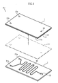
- the analytical instrument A2 of this embodiment includes a spacer 1A, a substrate 2A and a cover 2B.
- the spacer 1A is an example of first member of the present invention
- the substrate 2A and the cover 2B are examples of second member of the present invention.
- the spacer 1A comprises a flexible plate or sheet formed with a groove 30a penetrating thicknesswise for constituting a capillary 3A.
- the spacer 1A has an upper and a lower surfaces serving as bonding surfaces 11a, 11b made of self-adherent elastomer.
- the entirety of the spacer 1A may be made of self-adherent elastomer. In such a case, the spacer 1A can be manufactured easily.
- a pair of sheets 11 made of self-adherent elastomer may be bonded to an upper and a lower surfaces of a non-adherent base member 10A.
- Both of the substrate 2A and the cover 2B comprise a generally rectangular plate or sheet made of a non-adherent synthetic resin.
- the substrate 2A has an upper surface formed with a reaction portion 29 including a reagent, and a pair of electrodes 28a, 28b.
- the cover 2B is formed with a hole 27 for discharging air from the capillary 3A.
- the substrate 2A and the cover 2B are stacked to sandwich the spacer 1A in the thickness direction and bonded to the spacer 1A due to the adhesion of the bonding surfaces 11a, 11b of the spacer 1A.
- the upper and lower openings of the groove 30a of the spacer 1A is closed by the substrate 2A and the cover 2B, whereby the capillary 3A is defined.
- One end of the capillary 3A is open at an end surface of the analytical instrument 2A, and the opening serves as a sample introduction port 39.
- the concentration of a particular component in the sample can be measured by electrically detecting the degree of reaction by using a pair of electrodes 28a, 28b.
- concentration measurement principle is typically applicable to the measurement of a glucose level in blood, it is also applicable to concentration measurement of other components by changing the kind of the reagent in the reaction portion 29, for example.
- the substrate 2A and the cover 2B are directly bonded to the spacer 1A by utilizing adhesion of the bonding surfaces 11a, 11b. Therefore, similarly to the above analytical instrument A1, the bonding can be performed easily. Further, a capillary 3A of an intended size can be reliably formed. Therefore, the analytical instrument A2 does not suffer from such a problem that the amount of the sample reaching the reaction portion 29 becomes excessive or insufficient due to the improper size of the capillary 3A. In the analytical instrument A2, the entirety of the bonding surfaces 11a, 11b of the spacer 1A can be closely fitted to the substrate 2A and the cover 2B, respectively. Therefore, the same advantages as those of the analytical instrument A1, such as improved sealing performance at the periphery of the capillary 3A, can be obtained.
- upper and lower surfaces of the spacer 2C formed with a groove 30a are not self-adherent, and each of the substrate 1B and the cover 1C has a self-adherent bonding surface 11.
- the second member is sandwiched between two first members each of which is provided with a bonding surface made of self-adherent elastomer.
- the present invention can also employ such a structure.
- the present invention is applicable to any analytical instrument which includes at least two members bonded together and a capillary provided between the members, and the kind and components of the substance to be analyzed is not limitative.
- the manner of using the analytical instrument is not limitative.
- the specific configuration and the like of the first and the second members in the present invention may be appropriately changed in accordance with the usage.
- both of the first and the second members may have self-adherent bonding surfaces.
- the groove for constituting the capillary may be formed in either of the first member and the second member.
- the present invention is applicable also when the structural component of the analytical instrument is not made of a synthetic resin.
- a self-adherent elastomer exhibits a good adhesion also to glass, for example. Therefore, the present invention is applicable also when part of the structural component of the analytical instrument is made of e.g. glass and provides intended advantages.
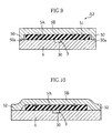
- Fig. 9 shows another embodiment of the present invention.
- the analytical instrument A3 of this embodiment includes a substrate 4, and a first and a second covers 5A, 5B. All of these structural components are non-adherent, and the analytical instrument A3 differs from the foregoing embodiments in that a self-adherent component is not used.
- the substrate 4 is an example of the first member of the present invention, whereas the first and the second covers 5A, 5B are examples of the second and the third members of the present invention.
- the substrate 4 comprises e.g. a rectangular plate or sheet made of a synthetic resin and has an upper surface formed with a bottomed groove 30 for constituting a capillary 3.
- the first cover 5A is made of an elastomer having an elastic modulus (modulus of elasticity) that is lower than those of the substrate 4 and the second cover 5B. Specific examples of material of the first cover 5A include polyvinylidene chloride and ethylene propylene rubber, but the material is not limited to these.
- the first cover 5A is in the form of a rectangular sheet slightly smaller than the substrate 4 and stacked on the upper surface of the substrate 4.
- the second cover 5B is in the form of a generally rectangular plate or sheet of a size which is larger than that of the first cover 5A and formed with a downwardly extending projection 50 at the entirety or almost entirety of the outer periphery.
- the second cover 5B covers the first cover 5A to accommodate the first cover 5A in a space 51 surrounded by the projection 50.
- the projection has a front end 50a (lower end) fused to the upper surface of the substrate 4. In the fusing, the second cover 5B compress the first cover 5A appropriately in the thickness direction.
- the analytical instrument A3 of this embodiment includes a capillary 3 defined by covering an upper opening of the groove 30 by the first cover 5A.
- the first cover 5A need not be bonded to the substrate 4 with an adhesive.
- the analytical instrument can be made by stacking the first and the second covers 5A, 5B on the substrate 4 and then fusing the outer periphery of the second cover 5B to the substrate 4 by heating utilizing a heater or ultrasonic wave. Therefore, the work is easy. Since the fusion of the second cover 5B and the substrate 4 is performed at a location away from the capillary 3, the fusing operation does not adversely affect the formation of the capillary 3.
- the first cover 5A is made of an elastomer and appropriately compressed by the pressing force of the second cover 5B, the first cover 5A closely fits to the upper surface of the substrate 4. Even when the substrate 4 is slightly warped, the first cover 5A is deformed correspondingly to the warp, so that the first cover 5A can be closely fitted to the substrate 4. Therefore, good sealing performance is provided at the periphery of the capillary 3.
- the first cover 5A is prevented from floating above the substrate 4. Therefore, the vertical dimension of the capillary 3 can be set precisely to an intended one.
- the analytical instrument according to the present invention can have a structure using a non-adherent elastomer.
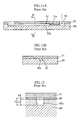
- the second cover 5B may comprise a flexible plate or sheet which is not provided with the projection 50.
- the portion 52 of the second cover 5B which projects outward to the periphery of the first cover 5A, may be laid on the substrate 4 and fused to the substrate.
- the first cover 5A can be pressed against the upper surface of the substrate 4 by the second cover 5B, whereby the same advantages as those of the analytical instrument A3 can be obtained.
- the means for bonding the second cover 5B to the substrate 4 is not limited to fusing, and an adhesive may be used.
- the adhesive is applied to the outer edges of the second cover 5B or the corresponding portion of the substrate 4. Unlike the prior art instrument, the adhesive need not be applied to the nearby portion of the capillary, so that the application is easy.
- the specific structure can be modified in various ways.
- the configuration of the substrate is not limited to the form of a sheet or plate.
Abstract
Description
- The present invention relates to an analytical instrument used for analyzing a sample in a liquid state such as a body fluid.
- Figs. 11A and 11B show an example of prior art analytical instrument. The analytical instrument includes a
substrate 90 and acover 91 stacked and bonded together to define acapillary 92. Thecapillary 92 is defined by closing an upper opening of agroove 92a formed at an upper surface of thesubstrate 90 by thecover 91. In the analytical instrument, when a sample in a liquid state is supplied to asample introduction port 93 formed in thecover 91, the sample travels through thecapillary 92 in a direction indicated by the arrow Na by capillary action. While the sample travels through thecapillary 92, the sample may be mixed with a reagent for causing a predetermined reaction or subjected to component separation, whereby the sample is analyzed. - Conventionally, the
substrate 90 and thecover 91 have sometimes been made of glass or silicone. In such a case, thesubstrate 90 and thecover 91 can be reliably bonded together by water glass bonding or anode bonding, for example. However, since the working of glass or silicone is not easy, the cost for manufacturing the analytical instrument disadvantageously increases. - In recent years, therefore, the
substrate 90 and thecover 91 are often made of a synthetic resin for decreasing the cost for the parts. In such a case, thesubstrate 90 and thecover 91 are often bonded together with an adhesive or by fusing utilizing ultrasonic wave. - However, such a prior art structure has the following problems.
- First, it is difficult to forma capillary 92 of an intended size. As shown in Fig. 12, when the
substrate 90 and thecover 91 are bonded together with an adhesive 80, the vertical dimension H of the capillary 92 (the dimension in the thickness direction of the analytical instrument) becomes the total dimension of the depth h1 of thegroove 92a and the thickness h2 of the adhesive 80. However, it is difficult to apply theadhesive 80 uniformly into a predetermined thickness. Therefore, due to the variation of the thickness of theadhesive 80, thecapillary 92 having an intended vertical dimension sometimes cannot be formed. In the case where ultrasonic wave is utilized, a projection in the form of a rib (not shown) is formed at a bonding surface, and ultrasonic wave is applied to the projection to heat and deform the projection. At this time, the portion to be deformed vibrates at an amplitude of about 10µm. Due to such vibration, the degree of deformation of the projection cannot be kept constant, so that thecapillary 92 of an intended size may not be formed. When the size of thecapillary 92 differs from an intended, proper one, conditions such as the travel speed or amount of the sample which flows through thecapillary 92 may differ from the intended conditions, which may cause inaccurate analysis results. - Secondly, the manufacturing of the analytical instrument is difficult when the configuration of the
capillary 92 is complicated. In applying theadhesive 80 to thesubstrate 90, thegroove 92a need be avoided so that theadhesive 80 does not enter thegroove 92a. Therefore, when the configuration of thecapillary 92 is complicated, the application of the adhesive following the configuration is troublesome and difficult. When ultrasonic wave is utilized, the projection for fusing need be formed correspondingly to the configuration of thecapillary 92. Therefore, in such a case again, the work is troublesome when the configuration of thecapillary 92 is complicated. - Thirdly, the sealing performance around the
capillary 92 is not good. For example, when the adhesive is not applied to a portion of the edge of thegroove 92a in applying theadhesive 80 to thesubstrate 90, the portion forms a gap communicating with thecapillary 92, causing a fear that the sample may unduly enter the portion. Such a fear exists also when ultrasonic wave is utilized. Particularly when thesubstrate 90 and thecover 91 are molded of resin, these members are sometimes warped to reduce the flatness at the bonding surfaces. In such a case, the sealing performance around thecapillary 92 is further deteriorated. - In recent years, studies are performed to reduce the size of an entire chemical analysis system by reducing the size of the structural parts of the system and integrating the parts. When the size of the chemical analysis system is reduced, the price of the system can be reduced. Further, since the analysis can be performed by using a smaller amount of sample, it is possible to reduce the time required for the analysis, the power consumption for actuating the system, and the amount of liquid wasted after the analysis. To reduce the size of the analytical instrument to follow the downsizing trend of the chemical analysis system, a considerably
small capillary 92 having a precisely intended size need be formed. However, it is difficult to meet such need when thesubstrate 90 and thecover 91 are bonded together with an adhesive or by utilizing ultrasonic wave. - An object of the present invention is to provide an analytical instrument capable of solving or lessening the above-described problems.
- According to a first aspect of the present invention, there is provided an analytical instrument comprising a first and a second members stacked on each other, and a capillary defined by covering an opening of a groove formed in one of the first and the second members with the other of the first and the second members. The first member includes a bonding surface made of self-adherent elastomer, and the first and second members are bonded together via the bonding surface.
- Preferably, the first member comprises a non-adherent base member and a sheet of self-adherent elastomer bonded to the base member, and the bonding surface comprises one surface of the sheet.
- Preferably, the first member is entirely made of self-adherent elastomer.
- Preferably, the second member is made of a non-adherent material, and the groove is formed in the second member.
- Preferably, the second member comprises a plate or sheet having one surface at which the groove is formed as a bottomed groove, and the first member is bonded to the one surface of the second member.
- Preferably, the capillary has one end branching into a plurality of paths, and the paths are formed with a sample receiving portion and a reagent receiving portion connected thereto. The capillary has another end formed with a reaction portion connected thereto for causing reaction between a sample and a reagent.
- Preferably, the analytical instrument according to the present invention includes a plurality of second members, and the first member comprises a plate or sheet in which the groove is formed to penetrate thicknesswise and which has an obverse surface and a reverse surface each serving as the bonding surface. The plurality of second members are bonded to the obverse surface and the reverse surface of the first member.
- Preferably, the analytical instrument according to the present invention includes a plurality of first members, and the second member comprises a plate or sheet in which the groove is formed to penetrate thicknesswise. The second member has an obverse and a reverse surfaces to which the first members are bonded.
- Preferably, the capillary has one end serving as a sample introduction port and includes a reaction portion containing a reagent.
- According to a second aspect of the present invention, there is provided an analytical instrument comprising a first and a second members stacked on each other, and a capillary defined by causing the second member to cover an opening of a groove formed in the first member. The second member is made of elastomer, and the analytical instrument further includes a third member for pressing the second member against the first member.
- Preferably, the second member is sandwiched between the first and the third members, and the third member is partially bonded to the first member at an outer periphery of the second member.
- Preferably, the third member includes a projection for engaging the first member at an outer periphery of the second member, and respective engaging portions of the projection and the first member are bonded together.
- Preferably, the third member comprises a flexible plate or sheet, and the third member being flexibly deformed so that an outer periphery of the third member comes into contact with the first member. Respective contacting portions of the third member and the first member are bonded together.
- Other features and advantages of the present invention will become clearer from the detailed description given below with reference to the accompanying drawings.
-
- Fig. 1 is a perspective view showing an embodiment of analytical instrument according to the present invention.
- Fig. 2 is a sectional view taken along lines II-II in Fig. 1.
- Fig. 3 is an exploded perspective view of the analytical instrument shown in Fig. 1.
- Fig. 4 is a perspective view showing another embodiment of analytical instrument according to the present invention.
- Fig. 5 is a sectional view taken along lines V-V in Fig. 4.
- Fig. 6 is an exploded perspective view of the analytical instrument shown in Fig. 4.
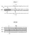
- Fig. 7 is a sectional view showing another example of spacer of the analytical instrument shown in Fig. 4.
- Fig. 8 is a sectional view showing another embodiment of analytical instrument according to the present invention.
- Fig. 9 is a sectional view showing another embodiment of analytical instrument according to the present invention.
- Fig. 10 is a sectional view showing another embodiment of analytical instrument according to the present invention.
- Fig. 11A is a sectional view showing a prior art structure, whereas Fig. 11B is a sectional view taken along lines XI-XI in Fig. 11A.
- Fig. 12 is an enlarged sectional view showing a principal portion of the prior art structure.
-
- Preferred embodiments of the present invention will be described below in detail with reference to the accompanying drawings.
- Figs. 1-3 show an embodiment of analytical instrument according to the present invention. The analytical instrument A1 of this embodiment includes a
cover 1, asubstrate 2 and acapillary 3 provided between the cover and the substrate. Thecover 1 and thesubstrate 2 are examples of a first and a second members of the present invention. - The
cover 1 comprises a flexible rectangular plate or sheet formed by laminating asheet 11 made of a self-adherent elastomer on abase member 10. Specifically, thesheet 11 may be made of silicone rubber. In the present invention, however, the material is not limited to a specific one, and other self-adherent elastomer may be used. However, it is preferable to use an elastomer that does not adversely affect the analysis results of the sample upon contact with the sample. Thesheet 11 has opposite surfaces both of which are adherent and is bonded to thebase member 10 by utilizing the adhesion of one of the opposite surfaces. The other one of the opposite surfaces serves as abonding surface 11a for bonding thecover 1 to thesubstrate 2. Thebase member 10 is made of a non-adherent synthetic resin. - The
substrate 2 comprises a plate or sheet having a rectangular configuration similar to that of thecover 1 and made of a non-adherent synthetic resin. Thesubstrate 2 has an upper surface formed with a narrow bottomedgroove 30 serving as thecapillary 3. Thegroove 30 is made serpentine to have a large length for promoting the mixing of a sample with a reagent, which will be described later. Thegroove 30 has opposite ends one of which is divided into two branches. The two branches are respectively connected to asample receiving portion 21a and areagent receiving portion 21b each in the form of a recess. The other end of thegroove 30 is connected to areaction portion 22 in the form of a recess. - The
cover 1 is stacked on thesubstrate 2 so that thebonding surface 11a comes into contact with the upper surface of thesubstrate 2 and bonded to thesubstrate 2 due to the adhesion of thebonding surface 11a. Thecapillary 3 is defined by closing an upper opening of thegroove 30 by thecover 1. Thecover 1 is formed with asample introduction port 15a and areagent introduction port 15b respectively communicating with thesample receiving portion 21a and thereagent receiving portion 21b of thesubstrate 2, and ameasurement opening 16 communicating with thereaction portion 22. - In the analytical instrument A1, when a sample and a reagent in a liquid state is supplied to the
sample introduction port 15a and thereagent introduction port 15b, the sample and the reagent travel through thecapillary 3 by capillary action to be mixed together and reaches thereaction portion 22 while undergoing certain reaction. The analysis of the sample may be performed by examining the optical characteristics of the liquid mixture of the sample and the reagent having reached thereaction portion 22 through themeasurement opening 16 using an optical measuring device (not shown), for example. - The analytical instrument A1 has a structure provided by directly bonding the
cover 1 and thesubstrate 2 to each other by utilizing the adhesion of thebonding surface 11a. Therefore, unlike the case in which the cover and the substrate are bonded together with an adhesive or by utilizing ultrasonic wave, the application of an adhesive to thecover 1 or thesubstrate 2 or the application of ultrasonic wave is not necessary. Therefore, the work for bonding thecover 1 and thesubstrate 2 is easy. Although thecapillary 3 has a complicated serpentine configuration, theflat bonding surface 11a of thecover 1 need not be worked otherwise. Therefore, thecover 1 can be made easily so that the analytical instrument A1 can be manufactured at a relatively low cost. - As noted above, the analytical instrument A1 is manufactured without using an adhesive. Therefore, unlike the prior art instrument which is made by using an adhesive, variation of the size of the
capillary 3 due to the variation of the thickness of the adhesive can be avoided. Therefore, acapillary 3 having just the intended size can be formed, so that the time taken for the sample and the reagent to reach thereaction portion 22 from thesample introduction port 15a and thereagent introduction port 15b or other conditions such as the degree of mixing can be prevented from becoming improper. - In bonding the
cover 1 and thesubstrate 2 together, thebonding surface 11a of thecover 1 can be closely fitted to the generally entire region of the upper surface of the substrate 2 (except for the intentionally recessed portion such as the portion formed with the groove 30). Therefore, the bonding strength of thecover 1 and thesubstrate 2 can be enhanced. Moreover, thecover 1 can be reliably bonded also to the edges of thegrove 30, whereby sealing performance at the periphery of thecapillary 3 can be enhanced. Even when the upper surface of thesubstrate 2 is curved due to the warp of thesubstrate 2, thecover 1 can be closely fitted to thesubstrate 2 by flexing thecover 1 correspondingly. - Figs. 4-7 illustrate another embodiment of analytical instrument according to the present invention. In Fig. 4 and the subsequent figures, the elements which are identical or similar to those of the foregoing embodiment are designated by the same reference signs as those used for the foregoing embodiment.
- The analytical instrument A2 of this embodiment includes a
spacer 1A, asubstrate 2A and acover 2B. Thespacer 1A is an example of first member of the present invention, whereas thesubstrate 2A and thecover 2B are examples of second member of the present invention. - The
spacer 1A comprises a flexible plate or sheet formed with agroove 30a penetrating thicknesswise for constituting acapillary 3A. Thespacer 1A has an upper and a lower surfaces serving asbonding surfaces spacer 1A bonding surfaces spacer 1A may be made of self-adherent elastomer. In such a case, thespacer 1A can be manufactured easily. Alternatively, as shown in Fig. 7, a pair ofsheets 11 made of self-adherent elastomer may be bonded to an upper and a lower surfaces of anon-adherent base member 10A. - Both of the
substrate 2A and thecover 2B comprise a generally rectangular plate or sheet made of a non-adherent synthetic resin. Thesubstrate 2A has an upper surface formed with areaction portion 29 including a reagent, and a pair ofelectrodes cover 2B is formed with ahole 27 for discharging air from thecapillary 3A. - The
substrate 2A and thecover 2B are stacked to sandwich thespacer 1A in the thickness direction and bonded to thespacer 1A due to the adhesion of thebonding surfaces spacer 1A. The upper and lower openings of thegroove 30a of thespacer 1A is closed by thesubstrate 2A and thecover 2B, whereby thecapillary 3A is defined. One end of the capillary 3A is open at an end surface of theanalytical instrument 2A, and the opening serves as asample introduction port 39. - In the analytical instrument A2, when a sample in a liquid state is supplied to the
sample introduction port 39, the sample moves through thecapillary 3A by capillary action and undergoes certain reaction upon reaching thereaction portion 29. For example, the concentration of a particular component in the sample can be measured by electrically detecting the degree of reaction by using a pair ofelectrodes reaction portion 29, for example. - In the analytical instrument A2, the
substrate 2A and thecover 2B are directly bonded to thespacer 1A by utilizing adhesion of thebonding surfaces capillary 3A of an intended size can be reliably formed. Therefore, the analytical instrument A2 does not suffer from such a problem that the amount of the sample reaching thereaction portion 29 becomes excessive or insufficient due to the improper size of thecapillary 3A. In the analytical instrument A2, the entirety of thebonding surfaces spacer 1A can be closely fitted to thesubstrate 2A and thecover 2B, respectively. Therefore, the same advantages as those of the analytical instrument A1, such as improved sealing performance at the periphery of thecapillary 3A, can be obtained. - The present invention is not limited to the foregoing embodiments. Specific structure of each component of the analytical instrument according to the present invention may be modified in various ways.
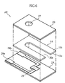
- In the structure shown in Fig. 8, upper and lower surfaces of the
spacer 2C formed with agroove 30a are not self-adherent, and each of thesubstrate 1B and thecover 1C has a self-adherent bonding surface 11. In other words, in this structure, the second member is sandwiched between two first members each of which is provided with a bonding surface made of self-adherent elastomer. The present invention can also employ such a structure. - The present invention is applicable to any analytical instrument which includes at least two members bonded together and a capillary provided between the members, and the kind and components of the substance to be analyzed is not limitative. The manner of using the analytical instrument is not limitative. The specific configuration and the like of the first and the second members in the present invention may be appropriately changed in accordance with the usage. In the present invention, both of the first and the second members may have self-adherent bonding surfaces. As will be understood from the above description, the groove for constituting the capillary may be formed in either of the first member and the second member.
- The present invention is applicable also when the structural component of the analytical instrument is not made of a synthetic resin. A self-adherent elastomer exhibits a good adhesion also to glass, for example. Therefore, the present invention is applicable also when part of the structural component of the analytical instrument is made of e.g. glass and provides intended advantages.
- Fig. 9 shows another embodiment of the present invention.
- The analytical instrument A3 of this embodiment includes a
substrate 4, and a first and a second covers 5A, 5B. All of these structural components are non-adherent, and the analytical instrument A3 differs from the foregoing embodiments in that a self-adherent component is not used. Thesubstrate 4 is an example of the first member of the present invention, whereas the first and the second covers 5A, 5B are examples of the second and the third members of the present invention. - The
substrate 4 comprises e.g. a rectangular plate or sheet made of a synthetic resin and has an upper surface formed with a bottomedgroove 30 for constituting acapillary 3. Thefirst cover 5A is made of an elastomer having an elastic modulus (modulus of elasticity) that is lower than those of thesubstrate 4 and thesecond cover 5B. Specific examples of material of thefirst cover 5A include polyvinylidene chloride and ethylene propylene rubber, but the material is not limited to these. Thefirst cover 5A is in the form of a rectangular sheet slightly smaller than thesubstrate 4 and stacked on the upper surface of thesubstrate 4. - The
second cover 5B is in the form of a generally rectangular plate or sheet of a size which is larger than that of thefirst cover 5A and formed with a downwardly extendingprojection 50 at the entirety or almost entirety of the outer periphery. Thesecond cover 5B covers thefirst cover 5A to accommodate thefirst cover 5A in aspace 51 surrounded by theprojection 50. The projection has afront end 50a (lower end) fused to the upper surface of thesubstrate 4. In the fusing, thesecond cover 5B compress thefirst cover 5A appropriately in the thickness direction. - The analytical instrument A3 of this embodiment includes a
capillary 3 defined by covering an upper opening of thegroove 30 by thefirst cover 5A. To manufacture the analytical instrument A3, thefirst cover 5A need not be bonded to thesubstrate 4 with an adhesive. The analytical instrument can be made by stacking the first and the second covers 5A, 5B on thesubstrate 4 and then fusing the outer periphery of thesecond cover 5B to thesubstrate 4 by heating utilizing a heater or ultrasonic wave. Therefore, the work is easy. Since the fusion of thesecond cover 5B and thesubstrate 4 is performed at a location away from thecapillary 3, the fusing operation does not adversely affect the formation of thecapillary 3. - Since the
first cover 5A is made of an elastomer and appropriately compressed by the pressing force of thesecond cover 5B, thefirst cover 5A closely fits to the upper surface of thesubstrate 4. Even when thesubstrate 4 is slightly warped, thefirst cover 5A is deformed correspondingly to the warp, so that thefirst cover 5A can be closely fitted to thesubstrate 4. Therefore, good sealing performance is provided at the periphery of thecapillary 3. Thefirst cover 5A is prevented from floating above thesubstrate 4. Therefore, the vertical dimension of thecapillary 3 can be set precisely to an intended one. - Like the above embodiment, the analytical instrument according to the present invention can have a structure using a non-adherent elastomer. The
second cover 5B may comprise a flexible plate or sheet which is not provided with theprojection 50. For example, as shown in Fig. 10, theportion 52 of thesecond cover 5B, which projects outward to the periphery of thefirst cover 5A, may be laid on thesubstrate 4 and fused to the substrate. In such a case again, thefirst cover 5A can be pressed against the upper surface of thesubstrate 4 by thesecond cover 5B, whereby the same advantages as those of the analytical instrument A3 can be obtained. The means for bonding thesecond cover 5B to thesubstrate 4 is not limited to fusing, and an adhesive may be used. In bonding thesecond cover 5B to thesubstrate 4 with an adhesive, the adhesive is applied to the outer edges of thesecond cover 5B or the corresponding portion of thesubstrate 4. Unlike the prior art instrument, the adhesive need not be applied to the nearby portion of the capillary, so that the application is easy. - As shown in Figs. 9 and 10, also in the analytical instrument of the present invention which utilizes a non-adherent elastomer, the specific structure can be modified in various ways. For example, the configuration of the substrate is not limited to the form of a sheet or plate.
Claims (13)
- An analytical instrument comprising:wherein the first member includes a bonding surface made of self-adherent elastomer; anda first and a second members stacked on each other; anda capillary defined by covering an opening of a groove formed in one of the first and second members with the other of the first and second members;
wherein the first and second members are bonded together via the bonding surface. - The analytical instrument according to claim 1, wherein the first member comprises a non-adherent base member and a sheet of self-adherent elastomer bonded to the base member; and
wherein the bonding surface comprises one surface of the sheet. - The analytical instrument according to claim 1, wherein the first member is entirely made of self-adherent elastomer.
- The analytical instrument according to claim 1, wherein the second member is made of a non-adherent material, and
wherein the groove is formed in the second member. - The analytical instrument according to claim 4, wherein the second member comprises a plate or sheet having one surface at which the groove is formed, the groove being a bottomed groove; and
wherein the first member is bonded to said one surface of the second member. - The analytical instrument according to claim 5, wherein the capillary has one end branching into a plurality of paths, the paths being formed with a sample receiving portion and a reagent receiving portion connected thereto, and wherein the capillary has another end formed with a reaction portion connected thereto for causing reaction between a sample and a reagent.
- The analytical instrument according to claim 1, wherein a plurality of second members are provided;
wherein the first member comprises a plate or sheet in which the groove is formed to penetrate thicknesswise and which has an obverse surface and a reverse surface each serving as the bonding surface; and
wherein the plurality of second members are bonded to the obverse surface and the reverse surface of the first member. - The analytical instrument according to claim 1, wherein a plurality of first members are provided;
wherein the second member comprises a plate or sheet in which the groove is formed to penetrate thicknesswise; and
wherein the second member has an obverse and a reverse surfaces to which the first members are bonded. - The analytical instrument according to claim 5, wherein the capillary has one end serving as a sample introduction port and includes a reaction portion containing a reagent.
- An analytical instrument comprising:wherein the second member is made of elastomer; anda first and a second members stacked on each other; anda capillary defined by causing the second member to cover an opening of a groove formed in the first member;
wherein the analytical instrument further includes a third member for pressing the second member against the first member. - The analytical instrument according to claim 10, wherein the second member is sandwiched between the first and the third members, and
wherein the third member is partially bonded to the first member at an outer periphery of the second member. - The analytical instrument according to claim 11, wherein the third member includes a projection for engaging the first member at an outer periphery of the second member, respective engaging portions of the projection and the first member being bonded together.
- The analytical instrument according to claim 11, wherein the third member comprises a flexible plate or sheet, the third member being flexibly deformed so that an outer periphery of the third member comes into contact with the first member, respective contacting portions of the third member and the first member being bonded together.
Priority Applications (1)
| Application Number | Priority Date | Filing Date | Title |
|---|---|---|---|
| EP08012106A EP1975628B1 (en) | 2002-04-30 | 2003-04-28 | Analytical instrument |
Applications Claiming Priority (3)
| Application Number | Priority Date | Filing Date | Title |
|---|---|---|---|
| JP2002128950 | 2002-04-30 | ||
| JP2002128950 | 2002-04-30 | ||
| PCT/JP2003/005479 WO2003093834A1 (en) | 2002-04-30 | 2003-04-28 | Analytical instrument |
Related Child Applications (1)
| Application Number | Title | Priority Date | Filing Date |
|---|---|---|---|
| EP08012106A Division EP1975628B1 (en) | 2002-04-30 | 2003-04-28 | Analytical instrument |
Publications (2)
| Publication Number | Publication Date |
|---|---|
| EP1500935A1 true EP1500935A1 (en) | 2005-01-26 |
| EP1500935A4 EP1500935A4 (en) | 2006-05-24 |
Family
ID=29397285
Family Applications (2)
| Application Number | Title | Priority Date | Filing Date |
|---|---|---|---|
| EP08012106A Expired - Lifetime EP1975628B1 (en) | 2002-04-30 | 2003-04-28 | Analytical instrument |
| EP03720977A Withdrawn EP1500935A4 (en) | 2002-04-30 | 2003-04-28 | Analytical instrument |
Family Applications Before (1)
| Application Number | Title | Priority Date | Filing Date |
|---|---|---|---|
| EP08012106A Expired - Lifetime EP1975628B1 (en) | 2002-04-30 | 2003-04-28 | Analytical instrument |
Country Status (7)
| Country | Link |
|---|---|
| US (1) | US7468162B2 (en) |
| EP (2) | EP1975628B1 (en) |
| JP (1) | JPWO2003093834A1 (en) |
| CN (1) | CN1650171B (en) |
| AT (1) | ATE543100T1 (en) |
| AU (1) | AU2003235968A1 (en) |
| WO (1) | WO2003093834A1 (en) |
Cited By (2)
| Publication number | Priority date | Publication date | Assignee | Title |
|---|---|---|---|---|
| EP2005155A2 (en) * | 2006-03-24 | 2008-12-24 | Advanced Animal Diagnostics | Microfluidic chamber assembly for mastitis assay |
| US8256285B2 (en) | 2007-08-21 | 2012-09-04 | BELIMO Holding, AG | Flow sensor including a base member with a resilient region forming a flow channel and a cover member covering the flow channel |
Families Citing this family (6)
| Publication number | Priority date | Publication date | Assignee | Title |
|---|---|---|---|---|
| JP2006030160A (en) * | 2004-04-14 | 2006-02-02 | Hitachi Maxell Ltd | Reaction container |
| NZ564141A (en) | 2005-05-09 | 2011-02-25 | Theranos Inc | Two way communication system for monitoring an analyte |
| US8741230B2 (en) | 2006-03-24 | 2014-06-03 | Theranos, Inc. | Systems and methods of sample processing and fluid control in a fluidic system |
| US11287421B2 (en) | 2006-03-24 | 2022-03-29 | Labrador Diagnostics Llc | Systems and methods of sample processing and fluid control in a fluidic system |
| EP3448565A1 (en) * | 2016-04-28 | 2019-03-06 | SABIC Global Technologies B.V. | Microfluid devices |
| DE102016226194A1 (en) * | 2016-12-23 | 2018-06-28 | Robert Bosch Gmbh | Microfluidic device, process for its production and injection-compression molding device |
Citations (7)
| Publication number | Priority date | Publication date | Assignee | Title |
|---|---|---|---|---|
| EP0359831A1 (en) * | 1988-03-31 | 1990-03-28 | Matsushita Electric Industrial Co., Ltd. | Biosensor and process for its production |
| US5595712A (en) * | 1994-07-25 | 1997-01-21 | E. I. Du Pont De Nemours And Company | Chemical mixing and reaction apparatus |
| WO1998045693A1 (en) * | 1997-04-04 | 1998-10-15 | Aclara Biosciences | Methods for fabricating enclosed microchannel structures |
| US6126765A (en) * | 1993-06-15 | 2000-10-03 | Pharmacia Biotech Ab | Method of producing microchannel/microcavity structures |
| US6197494B1 (en) * | 1987-04-03 | 2001-03-06 | Cardiovascular Diagnostics, Inc. | Apparatus for performing assays on liquid samples accurately, rapidly and simply |
| US20020023684A1 (en) * | 1998-01-20 | 2002-02-28 | Chow Calvin Y.H. | Multi-layer microfluidic devices |
| US20020029814A1 (en) * | 1999-06-28 | 2002-03-14 | Marc Unger | Microfabricated elastomeric valve and pump systems |
Family Cites Families (4)
| Publication number | Priority date | Publication date | Assignee | Title |
|---|---|---|---|---|
| JPH0658338B2 (en) * | 1988-05-18 | 1994-08-03 | 松下電器産業株式会社 | Biosensor |
| US6334301B1 (en) * | 1999-02-25 | 2002-01-01 | Vacco Industries, Inc. | Assembly of etched sheets forming a fluidic module |
| JP3418727B2 (en) | 2000-04-27 | 2003-06-23 | 独立行政法人産業技術総合研究所 | Micro valve device and method of manufacturing the same |
| JP2002048752A (en) | 2000-08-07 | 2002-02-15 | Nippon Telegr & Teleph Corp <Ntt> | Flow cell and polymer film forming method |
-
2003
- 2003-04-28 US US10/513,862 patent/US7468162B2/en active Active
- 2003-04-28 EP EP08012106A patent/EP1975628B1/en not_active Expired - Lifetime
- 2003-04-28 AU AU2003235968A patent/AU2003235968A1/en not_active Abandoned
- 2003-04-28 JP JP2004502002A patent/JPWO2003093834A1/en active Pending
- 2003-04-28 EP EP03720977A patent/EP1500935A4/en not_active Withdrawn
- 2003-04-28 CN CN038097923A patent/CN1650171B/en not_active Expired - Lifetime
- 2003-04-28 AT AT08012106T patent/ATE543100T1/en active
- 2003-04-28 WO PCT/JP2003/005479 patent/WO2003093834A1/en active Application Filing
Patent Citations (8)
| Publication number | Priority date | Publication date | Assignee | Title |
|---|---|---|---|---|
| US6197494B1 (en) * | 1987-04-03 | 2001-03-06 | Cardiovascular Diagnostics, Inc. | Apparatus for performing assays on liquid samples accurately, rapidly and simply |
| EP0359831A1 (en) * | 1988-03-31 | 1990-03-28 | Matsushita Electric Industrial Co., Ltd. | Biosensor and process for its production |
| US6176962B1 (en) * | 1990-02-28 | 2001-01-23 | Aclara Biosciences, Inc. | Methods for fabricating enclosed microchannel structures |
| US6126765A (en) * | 1993-06-15 | 2000-10-03 | Pharmacia Biotech Ab | Method of producing microchannel/microcavity structures |
| US5595712A (en) * | 1994-07-25 | 1997-01-21 | E. I. Du Pont De Nemours And Company | Chemical mixing and reaction apparatus |
| WO1998045693A1 (en) * | 1997-04-04 | 1998-10-15 | Aclara Biosciences | Methods for fabricating enclosed microchannel structures |
| US20020023684A1 (en) * | 1998-01-20 | 2002-02-28 | Chow Calvin Y.H. | Multi-layer microfluidic devices |
| US20020029814A1 (en) * | 1999-06-28 | 2002-03-14 | Marc Unger | Microfabricated elastomeric valve and pump systems |
Non-Patent Citations (1)
| Title |
|---|
| See also references of WO03093834A1 * |
Cited By (4)
| Publication number | Priority date | Publication date | Assignee | Title |
|---|---|---|---|---|
| EP2005155A2 (en) * | 2006-03-24 | 2008-12-24 | Advanced Animal Diagnostics | Microfluidic chamber assembly for mastitis assay |
| EP2005155A4 (en) * | 2006-03-24 | 2014-03-19 | Advanced Animal Diagnostics | Microfluidic chamber assembly for mastitis assay |
| US10983104B2 (en) | 2006-03-24 | 2021-04-20 | Advanced Animal Diagnostics, Inc. | Microfluidic chamber assembly for mastitis assay |
| US8256285B2 (en) | 2007-08-21 | 2012-09-04 | BELIMO Holding, AG | Flow sensor including a base member with a resilient region forming a flow channel and a cover member covering the flow channel |
Also Published As
| Publication number | Publication date |
|---|---|
| US20050201892A1 (en) | 2005-09-15 |
| CN1650171B (en) | 2012-10-03 |
| CN1650171A (en) | 2005-08-03 |
| JPWO2003093834A1 (en) | 2005-09-08 |
| ATE543100T1 (en) | 2012-02-15 |
| WO2003093834A1 (en) | 2003-11-13 |
| EP1500935A4 (en) | 2006-05-24 |
| EP1975628B1 (en) | 2012-01-25 |
| EP1975628A1 (en) | 2008-10-01 |
| AU2003235968A1 (en) | 2003-11-17 |
| US7468162B2 (en) | 2008-12-23 |
Similar Documents
| Publication | Publication Date | Title |
|---|---|---|
| US10828642B2 (en) | Integrated cartridge housings for sample analysis | |
| US7487682B2 (en) | Measuring cell as well as constructing methods for a measuring cell and measuring apparatus with a mount for such a measuring cell | |
| DK2394156T3 (en) | Device and method for electrochemical measurement of biochemical reactions as well as method of preparation for the device. | |
| US7468162B2 (en) | Analytical instrument | |
| CN111344062B (en) | Sensor cartridge | |
| US7544277B2 (en) | Electrochemical test sensors | |
| CN114867558B (en) | Analyte sensing system and cartridge therefor | |
| WO2021065777A1 (en) | Microchannel chip | |
| US20230271185A1 (en) | Biosensor system for multiplexed detection of biomarkers | |
| US20050210996A1 (en) | Flow channel structure and method | |
| CN111316072B (en) | Sensor assembly and method of using the same | |
| JP2016003922A (en) | Fluid handling device | |
| US6368478B1 (en) | Electrochemical measuring device with an planar sensor substrate | |
| US20110315549A1 (en) | Testing strip for detecting a fluidic sample | |
| WO2023204270A1 (en) | Assay device | |
| JP6310327B2 (en) | Fluid handling equipment | |
| EP3976255A1 (en) | Devices and methods for fluid actuation | |
| KR20200006819A (en) | Blood sugar bio sensor |
Legal Events
| Date | Code | Title | Description |
|---|---|---|---|
| PUAI | Public reference made under article 153(3) epc to a published international application that has entered the european phase |
Free format text: ORIGINAL CODE: 0009012 |
|
| 17P | Request for examination filed |
Effective date: 20041029 |
|
| AK | Designated contracting states |
Kind code of ref document: A1 Designated state(s): AT BE BG CH CY CZ DE DK EE ES FI FR GB GR HU IE IT LI LU MC NL PT RO SE SI SK TR |
|
| AX | Request for extension of the european patent |
Extension state: AL LT LV MK |
|
| RIC1 | Information provided on ipc code assigned before grant |
Ipc: G01N 33/543 20060101ALI20051216BHEP Ipc: G01N 37/00 20060101ALI20051216BHEP Ipc: G01N 31/20 20060101ALI20051216BHEP Ipc: G01N 27/28 20060101ALI20051216BHEP Ipc: G01N 33/52 20060101ALI20051216BHEP Ipc: G01N 1/00 20060101ALI20051216BHEP Ipc: G01N 1/10 20060101ALI20051216BHEP Ipc: G01N 35/08 20060101AFI20031118BHEP |
|
| A4 | Supplementary search report drawn up and despatched |
Effective date: 20060410 |
|
| R17C | First examination report despatched (corrected) |
Effective date: 20060713 |
|
| 17Q | First examination report despatched |
Effective date: 20060713 |
|
| STAA | Information on the status of an ep patent application or granted ep patent |
Free format text: STATUS: THE APPLICATION IS DEEMED TO BE WITHDRAWN |
|
| 18D | Application deemed to be withdrawn |
Effective date: 20080715 |