EP1501060A1 - A smoke alarm device - Google Patents
A smoke alarm device Download PDFInfo
- Publication number
- EP1501060A1 EP1501060A1 EP04394048A EP04394048A EP1501060A1 EP 1501060 A1 EP1501060 A1 EP 1501060A1 EP 04394048 A EP04394048 A EP 04394048A EP 04394048 A EP04394048 A EP 04394048A EP 1501060 A1 EP1501060 A1 EP 1501060A1
- Authority
- EP
- European Patent Office
- Prior art keywords
- alarm device
- alarm
- smoke alarm
- interconnect interface
- smoke
- Prior art date
- Legal status (The legal status is an assumption and is not a legal conclusion. Google has not performed a legal analysis and makes no representation as to the accuracy of the status listed.)
- Granted
Links
- 239000000779 smoke Substances 0.000 title claims abstract description 40
- 238000004891 communication Methods 0.000 claims abstract description 15
- 238000012360 testing method Methods 0.000 claims description 12
- 230000004913 activation Effects 0.000 claims description 6
- 230000005855 radiation Effects 0.000 claims description 6
- 230000003213 activating effect Effects 0.000 claims description 5
- 230000005540 biological transmission Effects 0.000 claims description 3
- 230000004044 response Effects 0.000 claims description 2
- 238000003825 pressing Methods 0.000 abstract description 2
- 238000010586 diagram Methods 0.000 description 3
- 238000009434 installation Methods 0.000 description 3
- WHXSMMKQMYFTQS-UHFFFAOYSA-N Lithium Chemical compound [Li] WHXSMMKQMYFTQS-UHFFFAOYSA-N 0.000 description 2
- 230000004888 barrier function Effects 0.000 description 2
- 229910052744 lithium Inorganic materials 0.000 description 2
- 238000000034 method Methods 0.000 description 2
- 230000015556 catabolic process Effects 0.000 description 1
- 238000010276 construction Methods 0.000 description 1
- 238000006731 degradation reaction Methods 0.000 description 1
- 230000000881 depressing effect Effects 0.000 description 1
- 238000004519 manufacturing process Methods 0.000 description 1
- 230000003287 optical effect Effects 0.000 description 1
- 230000008569 process Effects 0.000 description 1
- 230000009467 reduction Effects 0.000 description 1
- 238000009418 renovation Methods 0.000 description 1
Images


Classifications
-
- G—PHYSICS
- G08—SIGNALLING
- G08B—SIGNALLING OR CALLING SYSTEMS; ORDER TELEGRAPHS; ALARM SYSTEMS
- G08B25/00—Alarm systems in which the location of the alarm condition is signalled to a central station, e.g. fire or police telegraphic systems
- G08B25/003—Address allocation methods and details
-
- G—PHYSICS
- G08—SIGNALLING
- G08B—SIGNALLING OR CALLING SYSTEMS; ORDER TELEGRAPHS; ALARM SYSTEMS
- G08B17/00—Fire alarms; Alarms responsive to explosion
-
- G—PHYSICS
- G08—SIGNALLING
- G08B—SIGNALLING OR CALLING SYSTEMS; ORDER TELEGRAPHS; ALARM SYSTEMS
- G08B25/00—Alarm systems in which the location of the alarm condition is signalled to a central station, e.g. fire or police telegraphic systems
- G08B25/007—Details of data content structure of message packets; data protocols
-
- G—PHYSICS
- G08—SIGNALLING
- G08B—SIGNALLING OR CALLING SYSTEMS; ORDER TELEGRAPHS; ALARM SYSTEMS
- G08B25/00—Alarm systems in which the location of the alarm condition is signalled to a central station, e.g. fire or police telegraphic systems
- G08B25/009—Signalling of the alarm condition to a substation whose identity is signalled to a central station, e.g. relaying alarm signals in order to extend communication range
-
- G—PHYSICS
- G08—SIGNALLING
- G08B—SIGNALLING OR CALLING SYSTEMS; ORDER TELEGRAPHS; ALARM SYSTEMS
- G08B17/00—Fire alarms; Alarms responsive to explosion
- G08B17/10—Actuation by presence of smoke or gases, e.g. automatic alarm devices for analysing flowing fluid materials by the use of optical means
- G08B17/11—Actuation by presence of smoke or gases, e.g. automatic alarm devices for analysing flowing fluid materials by the use of optical means using an ionisation chamber for detecting smoke or gas
- G08B17/113—Constructional details
Definitions
- the invention relates to smoke alarm devices. This term should be interpreted to include any device for detecting fire or fire potential, for detecting smoke, gas, or heat.
- the invention is directed towards providing for simplified device installation.
- a smoke alarm device comprising a fire sensor, an alarm circuit for determining when an alarm condition exists and for generating an alarm, and an interconnect interface for communicating with other alarm devices in a network, characterised in that the interconnect interface communicates wirelessly, by radiation.
- the invention also provides a smoke alarm modular base comprising a housing, an interconnect interface for wireless communication with other devices in a network, and mains terminals for connection on one side to mains cables and on the other side to an alarm unit, and signal terminals for alarm status communication with an alarm unit with which it is connected to complete an alarm device.
- the radiation is radio frequency radiation.
- the interconnect interface uses frequency modulation.
- the interconnect interface comprises means for automatically testing integrity of interconnect communication among devices in a network.
- the interconnect interface comprises means for generating a user output, such as activating an LED, to indicate testing status.
- the interconnect interface comprises means for activating house coding for a network of devices in response to a user input.
- the interconnect interface maintains a count of the number of devices from which it has received a house-coding signal, and indicates the count to the user.
- the interconnect interface activates an LED in successive flashes to indicate the count.
- the activation is repeated at successive intervals such as 5 seconds.
- the interconnect interface is factory programmed with a unique device identifier code, during house coding it transmits said code and receives codes from other devices and saves them to a register, and generates the user indication according to the number of codes in the register.
- the interconnect interface recognises a received common default serial code and transmits said code in absence of house coding.
- the interconnect interface is programmable to operate as a repeater of an alarm signal.
- the interconnect interface modifies a received alarm signal before repeating it, to indicate that it is not original, and does not repeat alarm signals having a non-original indicating code.
- the interconnect interface wakes at pre-programmed intervals according to a timer, and an alarm trigger signal indicating an alarm condition transmitted by said interface is longer then said interval, and the circuit remains in wake mode until alarming ceases.
- the interface generates an alarm cancel signal a pre-set time after ceasing sensing an alarm condition.
- the interface ceases outputting an alarm output after expiry of a time-out period after sensing of an alarm condition.
- the device comprises an antenna, and means for moving the antenna between a retracted position and an extended position.
- the antenna in the retracted position extends peripherally in an arc within part of a housing of the device.
- the interconnect interface is housed within a modular base of the device, and the device further comprises an alarm unit for connection to the base.
- the base contains an independent back-up battery.
- the base comprises an interconnect interface activation switch configured to turn on when the alarm unit is secured to the base.
- the base and the alarm unit are configured for sliding push-fit interconnection, and the activation switch protrudes from a plane of the base so that it is pressed down as the alarm unit is fitted.
- the interconnect interface communicates with a message signal unit having a pre-defined fixed length, and it repeats signal units to build up to a desired transmission time.
- each message signal unit comprises a plurality of fields including a device identifier code.
- the fields include a code field indicating nature of the message, and a checksum field.
- a number of smoke alarm devices 1 to 7 are mounted in a number of rooms in a building.
- the devices 1 are mains-powered. However there is wireless communication between the devices for enhanced fire/smoke warning capability and ease of installation.
- the wireless communication is performed by a transceiver within each device 1, and the modulation is FM, at a frequency of 868MHz.
- the communication protocol is unique to networks of devices 1 and allows a large amount of information to be conveyed in a short communication duty cycle of 0.004%.
- the device 4 is configured by the installer to be a repeater unit. This merely involves an input for microcontroller software configuration.
- a modular base 10 of a device is shown.
- the base 10 is secured to a wall or ceiling, and a smoke alarm unit is pushed translationally for simultaneous mechanical and electrical interconnection so that mains power wired to the base 10 is delivered to the alarm unit.
- a smoke alarm unit is pushed translationally for simultaneous mechanical and electrical interconnection so that mains power wired to the base 10 is delivered to the alarm unit.
- This is in principle as described in our prior European Patent Specification No. EP1045354.
- the base 10 does much more than provide mains power. It contains an interconnect interface 30 for radio frequency (RF) communication with the other devices within its network. It also contains its own rechargeable power supply.
- RF radio frequency
- the base 10 comprises a base plate 12 having holes for securing to a ceiling or wall using screw fasteners. It also has an opening 13 for receiving mains power cables, which are connected to input terminals in a terminal block 20.
- an antenna 15 is initially curved around the periphery of the base 10.
- a frangible tab 16 allows it to be pulled out so that it extends outwardly, such as radially.
- Figs. 3(a) and 3(b) show preferred mutual orientations for the devices closest to each other, while Fig. 3(c) shows a poor mutual orientation.
- the antennae 15 may not need to be extended. If extension is required, the preferred orientations are as illustrated.
- the antenna arrangement allows excellent versatility.
- the terminal block 20 has output terminals 21 for push-fit connection with terminal spades of the alarm unit.
- the RF interconnect capability can be retro-fitted to existing alarm units of the push fit, type (as described in our prior EP1045354).
- the interconnect circuit contained within the base 10 is automatically powered up by its own battery because a protruding switch 25 is pressed down when the alarm unit slides over the base 10 during push-fitting.
- An OFF button 26 is also provided. This does not protrude, and is operated manually whenever the smoke alarm unit is removed from the base 10.
- the base 10 also comprises a "house-coding" switch 28 connected to a ramped actuator 27 which is accessible from the side using a screwdriver or similar tool pushed through an aperture 29 in the side wall.
- the base 10 includes the interconnect interface circuit 30 and power supply for interconnect functions.
- Input mains terminals 31 on one side of the terminal block 20 are connected to mains cables.
- a DC rectifier 32 supplies a regulator 34, in turn providing a 3.3V DC output for circuit operation. It also supplies a charging circuit 35, which provides a 6.6V DC charging potential to Lithium rechargeable batteries 36. Back-up power is provided by the Lithium rechargeable batteries 36.
- a DC rail 37 provides power for a transceiver 38 connected to the antenna 15.
- a 5-bit bus 39 links the transceiver 38 to a PIC microcontroller 40.
- the microcontroller 40 is connected by a link 41 to an output terminal 41 is the block 20 for communication with the alarm unit control circuit.
- the house coding switch 28 is connected to the mircrocontroller 40.
- the basic modulation parameters for the transceiver 38 are outlined above. In more detail, and referring to Fig. 6, the coding protocol includes the following segments:
- the message codes 41 are: F5, fire; C8, remote test; D5, alarm off; EB, remote hush; CA, learn mode; FC, remote locate; DB, standby F2, low battery; and D2, button test; C5, optical chamber degradation
- serial number includes the year and week of manufacture together with a four-digit code. This gives a very large number of possible codes, so that there is in practice almost no chance of interference with a neighbouring alarm device wireless network.
- the microcontroller 40 is programmed in software to perform the interconnect operations.
- each device 1 To install each device 1, an electrician connects the mains cables to the terminals in the block 20 and then slides the alarm unit until its terminal spades engage in the terminals 21. A screwdriver is then inserted into the slot 29 to contact the house coding switch ramp 27. This is repeated for all devices 1 of the network within a 15 minute timeframe. When activating the house coding switch 28, the electrician must wait until an amber LED is activated. He or she then checks that all devices 1 have communicated with each other by counting the number of times the amber light flashes on each device in turn. For example, if there are eight devices in the network, there should be eight flashes within a five-second period repeated every 5 seconds in each device.
- each device transmits every 5 seconds a signal stating that it is in the house coding mode and also transmitting its unique serial number. This is factory programmed to ROM. Every 5 seconds each unit will flash a light (e.g. a blue LED) to indicate the number of units it has identified. If it has not identified any unit, it will just flash once indicating there is just one unit, itself, in the network. As it detects a second unit it will flash twice, and so on. So, by simply checking that each of the 12 units is flashing its light 12 times, every 5 seconds, the installer can confirm that they are all operating.
- a light e.g. a blue LED
- each device saves in a register each successive serial number it receives. At the end of house coding each device should therefore store in its register a serial number for every other device of the network.
- a further feature is that while the units are in the house coding mode they will only acknowledge signals that are about 10 dB higher than its normal signal threshold. This helps to ensure that small reductions in the RF signal strength due for example, to furniture being moved or renovations will not lead to a loss of communication.
- the interconnect circuit 30 is programmed so that all units will communicate with each other as shipped using a default serial number "000 0001". If there is likely to be a potential problem with neighbouring units, there is a simple way (described above) of coding the units so they communicate with their own units, but ignore communications from other systems. Thus, the unique code of each device stored in its ROM is accessed only if the house coding switch is pressed.
- the installer can take a unit out of the program mode by repeating the sequence that caused it to go into program mode (e.g. 3 presses of the test button or pressing the program switch). Later on, further units can be added to the system by installing them and then simply putting the new units along with all the old units into program mode. If it is necessary to clear all the codes learned (e.g. if a unit was being transferred to a new system, or after a preliminary test) this can be done by simply holding the house code button down for 6 seconds, until the LED starts flashing. It could also alternatively be done by powering up the unit while holding down the house code switch - however this may be more awkward. On units with a separate program switch it can be done by powering up the unit while holding down the program switch.
- the device 1 may be in a building extension connected to the remainder of the building by an external wall and possibly having foil-backed plaster-board.
- all circuits 30 have the software capability to act as repeaters. The installer configures a selected device to be a repeater by holding the test button until the RF signal is being sent, (as indicated by the LED being on for 3.5 seconds), and then while the RF is being sent to press the house code switch. This well-defined procedure ensures a unit will not be made into a repeater inadvertently.
- the microcontroller 40 automatically re-broadcasts each alarm trigger message if it has been configured to act as a repeater. However, before doing so it flips the code in field 43 to indicate that the message is not original. Thus, a device in a "blind” location potentially receives the original alarm trigger message broadcast by the device which detected smoke and also the repeated one. Because field 43 has been "flipped" it is not repeated by the repeater device and the possible problem of perpetual broadcast of the alarm trigger message is avoided. Thus, by careful selection of the location of the repeater device or devices there is full coverage because there are multiple paths to even devices in "blind" locations.
- a timer in each circuit 30 "wakes" the circuit every 1.8 seconds.
- the trigger signal has a total duration of 3.5 seconds, thus ensuring that all devices can receive it.
- the actual message transmission takes 10ms, and so the trigger message is a message unit with the message code field 41 indicating alarm, repeated 350 times. Thereafter the unit sensing smoke transmits a continuing alarm message of 50ms duration (5 message units) every 5 seconds. These are all repeated by each repeater device, with the field 43 flipped.
- the microcontroller 40 is programmed to transmit a cancel message of 3.5 seconds duration, each message unit having a cancel code in the field 41. Also, each microcontroller 40 is programmed to cancel an alarm after absence of an alarm signal for 1 minute.
- the circuit 30 may also transmit an RF signal in a proprietary protocol or Bluetooth, for example, to a mobile network to cause one or more mobile stations to sound and possibly also to display text message. Also, it is envisaged that the circuits may transmit wirelessly status update signals to a control controller of the network. Such a controller could accordingly display basic status data such as fire alarm, battery-low, or system-OK status levels.
Abstract
Description
- The invention relates to smoke alarm devices. This term should be interpreted to include any device for detecting fire or fire potential, for detecting smoke, gas, or heat.
- In many situations it is specified that a number of such devices must be inter-linked so that they communicate with each other in a network. One problem arising from this is the task of installing the necessary cabling. Another problem is the tedium of testing that they all communicate correctly with each other. With say 12 smoke alarms, checking that they are all communicating can be quite a chore, often requiring two people. For example, one must check that the first unit communicates with all the other 11 units so that it can cause them to go into alarm. While one person holds down the test button on the first unit the other person goes around ensuring that all the other 11 are in alarm. This is then repeated with the second unit, and so on. This results in 11 x 12 = 132 combinations being checked - quite a tedious task. Further if there are problems with some units not communicating they will need to be re-sited and then the whole checking process repeated.
- The invention is directed towards providing for simplified device installation.
- According to the invention there is provided a smoke alarm device comprising a fire sensor, an alarm circuit for determining when an alarm condition exists and for generating an alarm, and an interconnect interface for communicating with other alarm devices in a network, characterised in that the interconnect interface communicates wirelessly, by radiation.
- In another aspect, the invention also provides a smoke alarm modular base comprising a housing, an interconnect interface for wireless communication with other devices in a network, and mains terminals for connection on one side to mains cables and on the other side to an alarm unit, and signal terminals for alarm status communication with an alarm unit with which it is connected to complete an alarm device.
- In one embodiment, the radiation is radio frequency radiation.
- In another embodiment, the interconnect interface uses frequency modulation.
- In a further embodiment, the interconnect interface comprises means for automatically testing integrity of interconnect communication among devices in a network.
- In one embodiment, the interconnect interface comprises means for generating a user output, such as activating an LED, to indicate testing status.
- In another embodiment, the interconnect interface comprises means for activating house coding for a network of devices in response to a user input.
- In a further embodiment, the interconnect interface maintains a count of the number of devices from which it has received a house-coding signal, and indicates the count to the user.
- In one embodiment, the interconnect interface activates an LED in successive flashes to indicate the count.
- In another embodiment, the activation is repeated at successive intervals such as 5 seconds.
- In a further embodiment, the interconnect interface is factory programmed with a unique device identifier code, during house coding it transmits said code and receives codes from other devices and saves them to a register, and generates the user indication according to the number of codes in the register.
- In one embodiment, the interconnect interface recognises a received common default serial code and transmits said code in absence of house coding.
- In another embodiment, the interconnect interface is programmable to operate as a repeater of an alarm signal.
- In a further embodiment, the interconnect interface modifies a received alarm signal before repeating it, to indicate that it is not original, and does not repeat alarm signals having a non-original indicating code.
- In one embodiment, the interconnect interface wakes at pre-programmed intervals according to a timer, and an alarm trigger signal indicating an alarm condition transmitted by said interface is longer then said interval, and the circuit remains in wake mode until alarming ceases.
- In another embodiment, the interface generates an alarm cancel signal a pre-set time after ceasing sensing an alarm condition.
- In a further embodiment, the interface ceases outputting an alarm output after expiry of a time-out period after sensing of an alarm condition.
- In one embodiment, the device comprises an antenna, and means for moving the antenna between a retracted position and an extended position.
- In another embodiment, in the retracted position the antenna extends peripherally in an arc within part of a housing of the device.
- In a further embodiment, the interconnect interface is housed within a modular base of the device, and the device further comprises an alarm unit for connection to the base.
- In one embodiment, the base contains an independent back-up battery.
- In another embodiment, the base comprises an interconnect interface activation switch configured to turn on when the alarm unit is secured to the base.
- In a further embodiment, the base and the alarm unit are configured for sliding push-fit interconnection, and the activation switch protrudes from a plane of the base so that it is pressed down as the alarm unit is fitted.
- In one embodiment, the interconnect interface communicates with a message signal unit having a pre-defined fixed length, and it repeats signal units to build up to a desired transmission time.
- In another embodiment, each message signal unit comprises a plurality of fields including a device identifier code.
- In a further embodiment, the fields include a code field indicating nature of the message, and a checksum field.
- The invention will be more clearly understood from the following description of some embodiments thereof, given by way of example only with reference to the accompanying drawings in which:-
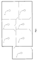
- Fig. 1 is a diagram showing a wireless network of smoke alarm devices within a domestic dwelling;
- Fig. 2 is a top perspective view of a modular base of a device;
- Fig. 3(a) and 3(b) are diagrams showing desired orientations of devices, while Fig. 3(c) shows an undesirable mutual orientation;
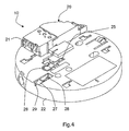
- Fig. 4 is an underneath perspective view of the modular base, showing the side which connects with an alarm unit;
- Fig. 5 is a block diagram of an interconnect circuit of the modular base; and
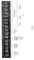
- Fig. 6 is a representation illustrating interconnect signal format.
-
- Referring to Fig. 1 a number of
smoke alarm devices 1 to 7 are mounted in a number of rooms in a building. Thedevices 1 are mains-powered. However there is wireless communication between the devices for enhanced fire/smoke warning capability and ease of installation. The wireless communication is performed by a transceiver within eachdevice 1, and the modulation is FM, at a frequency of 868MHz. The communication protocol is unique to networks ofdevices 1 and allows a large amount of information to be conveyed in a short communication duty cycle of 0.004%. In the network of Fig. 1 thedevice 4 is configured by the installer to be a repeater unit. This merely involves an input for microcontroller software configuration. - Referring to Figs 2, 3, and 4 a
modular base 10 of a device is shown. Thebase 10 is secured to a wall or ceiling, and a smoke alarm unit is pushed translationally for simultaneous mechanical and electrical interconnection so that mains power wired to thebase 10 is delivered to the alarm unit. This is in principle as described in our prior European Patent Specification No. EP1045354. - In this case, however, the
base 10 does much more than provide mains power. It contains aninterconnect interface 30 for radio frequency (RF) communication with the other devices within its network. It also contains its own rechargeable power supply. - The
base 10 comprises abase plate 12 having holes for securing to a ceiling or wall using screw fasteners. It also has anopening 13 for receiving mains power cables, which are connected to input terminals in aterminal block 20. As shown in Fig. 2 anantenna 15 is initially curved around the periphery of thebase 10. However afrangible tab 16 allows it to be pulled out so that it extends outwardly, such as radially. Figs. 3(a) and 3(b) show preferred mutual orientations for the devices closest to each other, while Fig. 3(c) shows a poor mutual orientation. Depending on the barriers within the building between the devices theantennae 15 may not need to be extended. If extension is required, the preferred orientations are as illustrated. The antenna arrangement allows excellent versatility. - The underneath of the base, where it connects with an alarm unit, is shown in Fig. 4. The
terminal block 20 hasoutput terminals 21 for push-fit connection with terminal spades of the alarm unit. By incorporating all interconnect functionality within thebase 10, the RF interconnect capability can be retro-fitted to existing alarm units of the push fit, type (as described in our prior EP1045354). The interconnect circuit contained within thebase 10 is automatically powered up by its own battery because a protrudingswitch 25 is pressed down when the alarm unit slides over the base 10 during push-fitting. AnOFF button 26 is also provided. This does not protrude, and is operated manually whenever the smoke alarm unit is removed from thebase 10. - The base 10 also comprises a "house-coding"
switch 28 connected to a rampedactuator 27 which is accessible from the side using a screwdriver or similar tool pushed through anaperture 29 in the side wall. - Referring to Fig. 5 the
base 10 includes theinterconnect interface circuit 30 and power supply for interconnect functions.Input mains terminals 31 on one side of theterminal block 20 are connected to mains cables. ADC rectifier 32 supplies aregulator 34, in turn providing a 3.3V DC output for circuit operation. It also supplies a chargingcircuit 35, which provides a 6.6V DC charging potential to Lithiumrechargeable batteries 36. Back-up power is provided by the Lithiumrechargeable batteries 36. ADC rail 37 provides power for atransceiver 38 connected to theantenna 15. A 5-bit bus 39 links thetransceiver 38 to aPIC microcontroller 40. Themicrocontroller 40 is connected by alink 41 to anoutput terminal 41 is theblock 20 for communication with the alarm unit control circuit. Thehouse coding switch 28 is connected to themircrocontroller 40. The basic modulation parameters for thetransceiver 38 are outlined above. In more detail, and referring to Fig. 6, the coding protocol includes the following segments: - 41, message code;
- 42, message length;
- 43, indicator of whether original or repeat;
- 44, checksum; and
- 45, serial number.
-
- The
message codes 41 are:F5, fire; C8, remote test; D5, alarm off; EB, remote hush; CA, learn mode; FC, remote locate; DB, standby F2, low battery; and D2, button test; C5, optical chamber degradation - As shown in Fig. 6 the serial number includes the year and week of manufacture together with a four-digit code. This gives a very large number of possible codes, so that there is in practice almost no chance of interference with a neighbouring alarm device wireless network.
- The
microcontroller 40 is programmed in software to perform the interconnect operations. - To install each
device 1, an electrician connects the mains cables to the terminals in theblock 20 and then slides the alarm unit until its terminal spades engage in theterminals 21. A screwdriver is then inserted into theslot 29 to contact the housecoding switch ramp 27. This is repeated for alldevices 1 of the network within a 15 minute timeframe. When activating thehouse coding switch 28, the electrician must wait until an amber LED is activated. He or she then checks that alldevices 1 have communicated with each other by counting the number of times the amber light flashes on each device in turn. For example, if there are eight devices in the network, there should be eight flashes within a five-second period repeated every 5 seconds in each device. - During house coding, within a 15 minute period each device transmits every 5 seconds a signal stating that it is in the house coding mode and also transmitting its unique serial number. This is factory programmed to ROM. Every 5 seconds each unit will flash a light (e.g. a blue LED) to indicate the number of units it has identified. If it has not identified any unit, it will just flash once indicating there is just one unit, itself, in the network. As it detects a second unit it will flash twice, and so on. So, by simply checking that each of the 12 units is flashing its light 12 times, every 5 seconds, the installer can confirm that they are all operating.
- If, say, two units are only flashing the blue LED 11 times, whereas the rest are flashing 12 times, it indicates that these two are not communicating with each other. They can then be re-sited or the antennae re-orientated until each flashes 12 times. The system can then be checked by clearing the coding in all 12 units (for example, by first powering up each unit with the test button held on, or by depressing a switch while powering up the unit, and then putting them into the checking mode as described above).
- During house coding, each device saves in a register each successive serial number it receives. At the end of house coding each device should therefore store in its register a serial number for every other device of the network.
- A further feature is that while the units are in the house coding mode they will only acknowledge signals that are about 10 dB higher than its normal signal threshold. This helps to ensure that small reductions in the RF signal strength due for example, to furniture being moved or renovations will not lead to a loss of communication.
- The
interconnect circuit 30 is programmed so that all units will communicate with each other as shipped using a default serial number "000 0001". If there is likely to be a potential problem with neighbouring units, there is a simple way (described above) of coding the units so they communicate with their own units, but ignore communications from other systems. Thus, the unique code of each device stored in its ROM is accessed only if the house coding switch is pressed. - For speed of installation the installer can take a unit out of the program mode by repeating the sequence that caused it to go into program mode (e.g. 3 presses of the test button or pressing the program switch). Later on, further units can be added to the system by installing them and then simply putting the new units along with all the old units into program mode. If it is necessary to clear all the codes learned (e.g. if a unit was being transferred to a new system, or after a preliminary test) this can be done by simply holding the house code button down for 6 seconds, until the LED starts flashing. It could also alternatively be done by powering up the unit while holding down the house code switch - however this may be more awkward. On units with a separate program switch it can be done by powering up the unit while holding down the program switch.
- Referring again to Fig. 1, it will be appreciated that some devices may not communicate with others because of barriers between them. For example, the
device 1 may be in a building extension connected to the remainder of the building by an external wall and possibly having foil-backed plaster-board. To address this issue, allcircuits 30 have the software capability to act as repeaters. The installer configures a selected device to be a repeater by holding the test button until the RF signal is being sent, (as indicated by the LED being on for 3.5 seconds), and then while the RF is being sent to press the house code switch. This well-defined procedure ensures a unit will not be made into a repeater inadvertently. - The
microcontroller 40 automatically re-broadcasts each alarm trigger message if it has been configured to act as a repeater. However, before doing so it flips the code infield 43 to indicate that the message is not original. Thus, a device in a "blind" location potentially receives the original alarm trigger message broadcast by the device which detected smoke and also the repeated one. Becausefield 43 has been "flipped" it is not repeated by the repeater device and the possible problem of perpetual broadcast of the alarm trigger message is avoided. Thus, by careful selection of the location of the repeater device or devices there is full coverage because there are multiple paths to even devices in "blind" locations. - A timer in each
circuit 30 "wakes" the circuit every 1.8 seconds. The trigger signal has a total duration of 3.5 seconds, thus ensuring that all devices can receive it. The actual message transmission takes 10ms, and so the trigger message is a message unit with themessage code field 41 indicating alarm, repeated 350 times. Thereafter the unit sensing smoke transmits a continuing alarm message of 50ms duration (5 message units) every 5 seconds. These are all repeated by each repeater device, with thefield 43 flipped. Themicrocontroller 40 is programmed to transmit a cancel message of 3.5 seconds duration, each message unit having a cancel code in thefield 41. Also, eachmicrocontroller 40 is programmed to cancel an alarm after absence of an alarm signal for 1 minute. - It is envisaged that the
circuit 30 may also transmit an RF signal in a proprietary protocol or Bluetooth, for example, to a mobile network to cause one or more mobile stations to sound and possibly also to display text message. Also, it is envisaged that the circuits may transmit wirelessly status update signals to a control controller of the network. Such a controller could accordingly display basic status data such as fire alarm, battery-low, or system-OK status levels. - The invention is not limited to the embodiments described but may be varied in construction and detail.
Claims (26)
- A smoke alarm device comprising a fire sensor, an alarm circuit for determining when an alarm condition exists and for generating an alarm, and an interconnect interface for communicating with other alarm devices in a network, characterised in that the interconnect interface communicates wirelessly, by radiation.
- A smoke alarm device as claimed in claim 1, wherein the radiation is radio frequency radiation.
- A smoke alarm device as claimed in claim 1 or 2, wherein the interconnect interface uses frequency modulation.
- A smoke alarm device as claimed in any preceding claim, wherein the interconnect interface comprises means for automatically tests integrity of interconnect communication among devices in a network.
- A smoke alarm device as claimed in any preceding claim, wherein the interconnect interface comprises means for generating a user output, such as activating an LED, to indicate testing status.
- A smoke alarm device as claimed in claims 4 or 5, wherein the interconnect interface comprises means for activating house coding for a network of devices in response to a user input.
- A smoke alarm device as claimed in claim 6, wherein the interconnect interface maintains a count of the number of devices from which it has received a house-coding signal, and indicates the count to the user.
- A smoke alarm device as claimed in claim 7, wherein the interconnect interface activates an LED in successive flashes to indicate the count.
- A smoke alarm device as claimed in claim 8, wherein the activation is repeated at successive intervals such as 5 seconds.
- A smoke alarm device as claimed in any of claims 7 to 9, wherein the interconnect interface is factory programmed with a unique device identifier code, during house coding it transmits said code and receives codes from other devices and saves them to a register, and generates the user indication according to the number of codes in the register.
- A smoke alarm device as claimed in claim 10, wherein the interconnect interface recognises a received common default serial code and transmits said code in absence of house coding.
- A smoke alarm device as claimed in any preceding claim, wherein the interconnect interface is programmable to operate as a repeater of an alarm signal.
- A smoke alarm device as claimed in claim 12, wherein the interconnect interface modifies a received alarm signal before repeating it, to indicate that it is not original, and does not repeat alarm signals having a non-original indicating code.
- A smoke alarm device as claimed in any preceding claim, wherein the interconnect interface wakes at pre-programmed intervals according to a timer, and an alarm trigger signal indicating an alarm condition transmitted by said interface is longer then said interval, and the circuit remains in wake mode until alarming ceases.
- A smoke alarm device as claimed in claim 14, wherein the interface generates an alarm cancel signal a pre-set time after ceasing sensing an alarm condition.
- A smoke alarm device as claimed in any preceding claim, wherein the interface ceases outputting an alarm output after expiry of a time-out period after sensing of an alarm condition.
- A smoke alarm device as claimed in any preceding claim, wherein the device comprises an antenna, and means for moving the antenna between a retracted position and an extended position.
- A smoke alarm device as claimed in claim 17, wherein in the retracted position the antenna extends peripherally in an arc within part of a housing of the device, and the device further comprises an alarm unit for connection to the base.
- A smoke alarm device as claimed in any preceding claim, wherein the interconnect interface is housed within a modular base of the device.
- A smoke alarm device as claimed in claim 19, wherein the base contains an independent back-up battery.
- A smoke alarm device as claimed in claims 19 or 20, wherein the base comprises an interconnect interface activation switch configured to turn on when the alarm unit is secured to the base.
- A smoke alarm device as claimed in claim 21, wherein the base and the alarm unit are also configured for sliding push-fit interconnection, and the activation switch protrudes from a plane of the base so that it is pressed down as the alarm unit is fitted.
- A smoke alarm device as claimed in any preceding claim, wherein the interconnect interface communicates with a message signal unit having a pre-defined fixed length, and it repeats signal units to build up to a desired transmission time according to the information being conveyed.
- A smoke alarm device as claimed in claim 23, wherein each message signal unit comprises a plurality of fields including a device identifier code.
- A smoke alarm device as claimed in claim 24, wherein the fields include a code field indicating nature of the message, and a checksum field.
- A smoke alarm modular base comprising a housing, an interconnect interface for wireless communication with other devices in a network, and mains terminals for connection on one side to mains cables and on the other side to an alarm unit, and signal terminals for alarm status communication with an alarm unit with which it is connected to complete an alarm device.
Applications Claiming Priority (2)
| Application Number | Priority Date | Filing Date | Title |
|---|---|---|---|
| IE20030551 | 2003-07-25 | ||
| IE20030551 | 2003-07-25 |
Publications (2)
| Publication Number | Publication Date |
|---|---|
| EP1501060A1 true EP1501060A1 (en) | 2005-01-26 |
| EP1501060B1 EP1501060B1 (en) | 2007-11-21 |
Family
ID=33485277
Family Applications (1)
| Application Number | Title | Priority Date | Filing Date |
|---|---|---|---|
| EP04394048A Active EP1501060B1 (en) | 2003-07-25 | 2004-07-26 | A smoke alarm device |
Country Status (3)
| Country | Link |
|---|---|
| EP (1) | EP1501060B1 (en) |
| DE (1) | DE602004010202T2 (en) |
| IE (1) | IES20040503A2 (en) |
Cited By (12)
| Publication number | Priority date | Publication date | Assignee | Title |
|---|---|---|---|---|
| GB2423397A (en) * | 2005-02-18 | 2006-08-23 | Locca Tech Ltd | Wireless smoke alarm system |
| WO2006087566A1 (en) * | 2005-02-18 | 2006-08-24 | Locca Tech Ltd | Wireless remote controllable fire and smoke alarm system |
| EP1710765A1 (en) * | 2005-04-07 | 2006-10-11 | Siemens Schweiz AG | Radio hazard signalling system |
| WO2006116800A1 (en) * | 2005-05-02 | 2006-11-09 | Ian Maxwell Griffiths | Emergency apparatus with remote trigger |
| WO2007137564A1 (en) * | 2006-05-31 | 2007-12-06 | Merten Gmbh & Co. Kg | Monitoring system |
| EP1903523A1 (en) * | 2006-09-21 | 2008-03-26 | E.I. Technology Limited | Alarm systems |
| WO2010097965A1 (en) * | 2009-02-27 | 2010-09-02 | Panasonic Electric Works Co., Ltd. | Home security surveillance system |
| EP2264681A1 (en) * | 2008-03-24 | 2010-12-22 | Hochiki Corporation | Alarm |
| EP2581891A2 (en) | 2011-10-12 | 2013-04-17 | E.I. Technology Limited | A low current RF alarm device mesh network |
| US8514074B2 (en) | 2008-05-08 | 2013-08-20 | Hochiki Corporation | Alarm |
| EP2843636A1 (en) | 2013-08-23 | 2015-03-04 | E.I. Technology Limited | Monitoring and control of alarm systems |
| EP2996099A1 (en) * | 2014-09-09 | 2016-03-16 | Simplex Time Recorder Co. | Modular wireless mass evacuation notification system |
Families Citing this family (1)
| Publication number | Priority date | Publication date | Assignee | Title |
|---|---|---|---|---|
| FR2973545B1 (en) | 2011-03-31 | 2013-04-12 | Finsecur | ALARM TRIP DEVICE FOR A SECURITY SYSTEM AND A METHOD FOR INSTALLING AN ALARM TRIP DEVICE |
Citations (4)
| Publication number | Priority date | Publication date | Assignee | Title |
|---|---|---|---|---|
| WO1992004758A1 (en) * | 1990-09-04 | 1992-03-19 | Minitronics Pty. Ltd. | Improved communications and testing for emergency lighting systems |
| US5587705A (en) * | 1994-08-29 | 1996-12-24 | Morris; Gary J. | Multiple alert smoke detector |
| US6078269A (en) * | 1997-11-10 | 2000-06-20 | Safenight Technology Inc. | Battery-powered, RF-interconnected detector sensor system |
| US20010038336A1 (en) * | 1999-01-23 | 2001-11-08 | James Acevedo | Wireless smoke detection system |
-
2004
- 2004-07-26 EP EP04394048A patent/EP1501060B1/en active Active
- 2004-07-26 DE DE602004010202T patent/DE602004010202T2/en active Active
- 2004-07-26 IE IE20040503A patent/IES20040503A2/en not_active IP Right Cessation
Patent Citations (4)
| Publication number | Priority date | Publication date | Assignee | Title |
|---|---|---|---|---|
| WO1992004758A1 (en) * | 1990-09-04 | 1992-03-19 | Minitronics Pty. Ltd. | Improved communications and testing for emergency lighting systems |
| US5587705A (en) * | 1994-08-29 | 1996-12-24 | Morris; Gary J. | Multiple alert smoke detector |
| US6078269A (en) * | 1997-11-10 | 2000-06-20 | Safenight Technology Inc. | Battery-powered, RF-interconnected detector sensor system |
| US20010038336A1 (en) * | 1999-01-23 | 2001-11-08 | James Acevedo | Wireless smoke detection system |
Cited By (24)
| Publication number | Priority date | Publication date | Assignee | Title |
|---|---|---|---|---|
| WO2006087566A1 (en) * | 2005-02-18 | 2006-08-24 | Locca Tech Ltd | Wireless remote controllable fire and smoke alarm system |
| GB2423397A (en) * | 2005-02-18 | 2006-08-23 | Locca Tech Ltd | Wireless smoke alarm system |
| EP1710765A1 (en) * | 2005-04-07 | 2006-10-11 | Siemens Schweiz AG | Radio hazard signalling system |
| WO2006106037A1 (en) * | 2005-04-07 | 2006-10-12 | Siemens Schweiz Ag | Radio danger warning system |
| WO2006116800A1 (en) * | 2005-05-02 | 2006-11-09 | Ian Maxwell Griffiths | Emergency apparatus with remote trigger |
| WO2007137564A1 (en) * | 2006-05-31 | 2007-12-06 | Merten Gmbh & Co. Kg | Monitoring system |
| EP1903523A1 (en) * | 2006-09-21 | 2008-03-26 | E.I. Technology Limited | Alarm systems |
| US8493203B2 (en) | 2008-03-24 | 2013-07-23 | Hochiki Corporation | Alarm device |
| AU2009230304B2 (en) * | 2008-03-24 | 2013-09-19 | Hochiki Corporation | Alarm Device |
| EP2264681A1 (en) * | 2008-03-24 | 2010-12-22 | Hochiki Corporation | Alarm |
| EP2264681A4 (en) * | 2008-03-24 | 2013-06-05 | Hochiki Co | Alarm |
| US8514074B2 (en) | 2008-05-08 | 2013-08-20 | Hochiki Corporation | Alarm |
| WO2010097965A1 (en) * | 2009-02-27 | 2010-09-02 | Panasonic Electric Works Co., Ltd. | Home security surveillance system |
| EP2581891A2 (en) | 2011-10-12 | 2013-04-17 | E.I. Technology Limited | A low current RF alarm device mesh network |
| EP2843636A1 (en) | 2013-08-23 | 2015-03-04 | E.I. Technology Limited | Monitoring and control of alarm systems |
| EP2843636B1 (en) | 2013-08-23 | 2018-06-13 | E.I. Technology | Monitoring and control of alarm systems |
| EP2996099A1 (en) * | 2014-09-09 | 2016-03-16 | Simplex Time Recorder Co. | Modular wireless mass evacuation notification system |
| US9728074B2 (en) | 2014-09-09 | 2017-08-08 | Tyco Fire & Security Gmbh | Modular wireless mass evacuation notification system |
| US9875644B2 (en) | 2014-09-09 | 2018-01-23 | Tyco Fire & Security Gmbh | Master slave wireless fire alarm and mass notification system |
| US10212664B2 (en) | 2014-09-09 | 2019-02-19 | Tyco Fire & Security Gmbh | Modular wireless mass evacuation notification system |
| US10470127B2 (en) | 2014-09-09 | 2019-11-05 | Johnson Controls Fire Protection LP | Master slave wireless fire alarm and mass notification system |
| US10477477B2 (en) | 2014-09-09 | 2019-11-12 | Johnson Controls Fire Protection LP | Modular wireless mass evacuation notification system |
| US10555262B2 (en) | 2014-09-09 | 2020-02-04 | Johnson Controls Fire Protection LP | Modular wireless mass evacuation notification system |
| US10966154B2 (en) | 2014-09-09 | 2021-03-30 | Johnson Controls Fire Protection LP | Master slave wireless fire alarm and mass notification system |
Also Published As
| Publication number | Publication date |
|---|---|
| IES20040503A2 (en) | 2005-03-23 |
| DE602004010202D1 (en) | 2008-01-03 |
| IE20040505A1 (en) | 2005-03-23 |
| EP1501060B1 (en) | 2007-11-21 |
| DE602004010202T2 (en) | 2008-09-25 |
Similar Documents
| Publication | Publication Date | Title |
|---|---|---|
| EP1501060B1 (en) | A smoke alarm device | |
| EP2060156B1 (en) | Procedure for addressing remotely-located radio frequency components of a control system | |
| CN101523991B (en) | Method of restoring a remote wireless control device to a known state | |
| US9655216B2 (en) | Luminaire and illumination system | |
| EP2060157B1 (en) | Method and system of establishing communication with wireless control devices | |
| US7126291B2 (en) | Radio frequency lighting control system programming device and method | |
| EP1729171A1 (en) | Radio remote control for photographic equipment | |
| EP2498233A1 (en) | Relay method for alarm system and alarm | |
| US20060208877A1 (en) | Conformal repeater unit | |
| EP1903523B1 (en) | Alarm systems | |
| US20090212961A1 (en) | Wireless remote controllable fire and smoke alarm system | |
| EP1724903A2 (en) | Integrated system for lighting and emergency lighting | |
| JP4389549B2 (en) | Lighting communication system | |
| JP2009032543A (en) | Lighting device, lighting system, and guiding light | |
| EP1035628A1 (en) | Improvements relating to emergency lighting units and installations | |
| GB2423397A (en) | Wireless smoke alarm system | |
| IE20040503U1 (en) | A smoke alarm device | |
| JP4803287B2 (en) | Lighting communication system | |
| JP4003474B2 (en) | Lighting device | |
| IES83854Y1 (en) | A smoke alarm device | |
| IE84058B1 (en) | A smoke alarm device | |
| EP2897396B1 (en) | Wireless communication system | |
| JP4981859B2 (en) | Lighting communication system | |
| JP3966476B2 (en) | Wireless monitoring system and control method | |
| JP2018085281A (en) | Illuminating device with radio communication function |
Legal Events
| Date | Code | Title | Description |
|---|---|---|---|
| PUAI | Public reference made under article 153(3) epc to a published international application that has entered the european phase |
Free format text: ORIGINAL CODE: 0009012 |
|
| AK | Designated contracting states |
Kind code of ref document: A1 Designated state(s): AT BE BG CH CY CZ DE DK EE ES FI FR GB GR HU IE IT LI LU MC NL PL PT RO SE SI SK TR |
|
| AX | Request for extension of the european patent |
Extension state: AL HR LT LV MK |
|
| 17P | Request for examination filed |
Effective date: 20050519 |
|
| 17Q | First examination report despatched |
Effective date: 20050623 |
|
| AKX | Designation fees paid |
Designated state(s): AT BE BG CH CY CZ DE DK EE ES FI FR GB GR HU IE IT LI LU MC NL PL PT RO SE SI SK TR |
|
| GRAP | Despatch of communication of intention to grant a patent |
Free format text: ORIGINAL CODE: EPIDOSNIGR1 |
|
| GRAS | Grant fee paid |
Free format text: ORIGINAL CODE: EPIDOSNIGR3 |
|
| GRAA | (expected) grant |
Free format text: ORIGINAL CODE: 0009210 |
|
| RBV | Designated contracting states (corrected) |
Designated state(s): AT BE BG CH CY CZ DE DK EE ES FI FR GB GR HU IT LI LU MC NL PL PT RO SE SI SK TR |
|
| AK | Designated contracting states |
Kind code of ref document: B1 Designated state(s): AT BE BG CH CY CZ DE DK EE ES FI FR GB GR HU IT LI LU MC NL PL PT RO SE SI SK TR |
|
| REG | Reference to a national code |
Ref country code: GB Ref legal event code: FG4D |
|
| REG | Reference to a national code |
Ref country code: CH Ref legal event code: EP |
|
| REF | Corresponds to: |
Ref document number: 602004010202 Country of ref document: DE Date of ref document: 20080103 Kind code of ref document: P |
|
| PG25 | Lapsed in a contracting state [announced via postgrant information from national office to epo] |
Ref country code: ES Free format text: LAPSE BECAUSE OF FAILURE TO SUBMIT A TRANSLATION OF THE DESCRIPTION OR TO PAY THE FEE WITHIN THE PRESCRIBED TIME-LIMIT Effective date: 20080304 Ref country code: CH Free format text: LAPSE BECAUSE OF FAILURE TO SUBMIT A TRANSLATION OF THE DESCRIPTION OR TO PAY THE FEE WITHIN THE PRESCRIBED TIME-LIMIT Effective date: 20071121 Ref country code: SE Free format text: LAPSE BECAUSE OF FAILURE TO SUBMIT A TRANSLATION OF THE DESCRIPTION OR TO PAY THE FEE WITHIN THE PRESCRIBED TIME-LIMIT Effective date: 20080221 Ref country code: LI Free format text: LAPSE BECAUSE OF FAILURE TO SUBMIT A TRANSLATION OF THE DESCRIPTION OR TO PAY THE FEE WITHIN THE PRESCRIBED TIME-LIMIT Effective date: 20071121 |
|
| PG25 | Lapsed in a contracting state [announced via postgrant information from national office to epo] |
Ref country code: SI Free format text: LAPSE BECAUSE OF FAILURE TO SUBMIT A TRANSLATION OF THE DESCRIPTION OR TO PAY THE FEE WITHIN THE PRESCRIBED TIME-LIMIT Effective date: 20071121 Ref country code: PL Free format text: LAPSE BECAUSE OF FAILURE TO SUBMIT A TRANSLATION OF THE DESCRIPTION OR TO PAY THE FEE WITHIN THE PRESCRIBED TIME-LIMIT Effective date: 20071121 Ref country code: FI Free format text: LAPSE BECAUSE OF FAILURE TO SUBMIT A TRANSLATION OF THE DESCRIPTION OR TO PAY THE FEE WITHIN THE PRESCRIBED TIME-LIMIT Effective date: 20071121 Ref country code: BG Free format text: LAPSE BECAUSE OF FAILURE TO SUBMIT A TRANSLATION OF THE DESCRIPTION OR TO PAY THE FEE WITHIN THE PRESCRIBED TIME-LIMIT Effective date: 20080221 |
|
| REG | Reference to a national code |
Ref country code: CH Ref legal event code: PL |
|
| PG25 | Lapsed in a contracting state [announced via postgrant information from national office to epo] |
Ref country code: AT Free format text: LAPSE BECAUSE OF FAILURE TO SUBMIT A TRANSLATION OF THE DESCRIPTION OR TO PAY THE FEE WITHIN THE PRESCRIBED TIME-LIMIT Effective date: 20071121 |
|
| PG25 | Lapsed in a contracting state [announced via postgrant information from national office to epo] |
Ref country code: DK Free format text: LAPSE BECAUSE OF FAILURE TO SUBMIT A TRANSLATION OF THE DESCRIPTION OR TO PAY THE FEE WITHIN THE PRESCRIBED TIME-LIMIT Effective date: 20071121 Ref country code: CZ Free format text: LAPSE BECAUSE OF FAILURE TO SUBMIT A TRANSLATION OF THE DESCRIPTION OR TO PAY THE FEE WITHIN THE PRESCRIBED TIME-LIMIT Effective date: 20071121 |
|
| PG25 | Lapsed in a contracting state [announced via postgrant information from national office to epo] |
Ref country code: SK Free format text: LAPSE BECAUSE OF FAILURE TO SUBMIT A TRANSLATION OF THE DESCRIPTION OR TO PAY THE FEE WITHIN THE PRESCRIBED TIME-LIMIT Effective date: 20071121 Ref country code: RO Free format text: LAPSE BECAUSE OF FAILURE TO SUBMIT A TRANSLATION OF THE DESCRIPTION OR TO PAY THE FEE WITHIN THE PRESCRIBED TIME-LIMIT Effective date: 20071121 Ref country code: BE Free format text: LAPSE BECAUSE OF FAILURE TO SUBMIT A TRANSLATION OF THE DESCRIPTION OR TO PAY THE FEE WITHIN THE PRESCRIBED TIME-LIMIT Effective date: 20071121 |
|
| PLBE | No opposition filed within time limit |
Free format text: ORIGINAL CODE: 0009261 |
|
| STAA | Information on the status of an ep patent application or granted ep patent |
Free format text: STATUS: NO OPPOSITION FILED WITHIN TIME LIMIT |
|
| PG25 | Lapsed in a contracting state [announced via postgrant information from national office to epo] |
Ref country code: PT Free format text: LAPSE BECAUSE OF FAILURE TO SUBMIT A TRANSLATION OF THE DESCRIPTION OR TO PAY THE FEE WITHIN THE PRESCRIBED TIME-LIMIT Effective date: 20080421 |
|
| 26N | No opposition filed |
Effective date: 20080822 |
|
| PG25 | Lapsed in a contracting state [announced via postgrant information from national office to epo] |
Ref country code: FR Free format text: LAPSE BECAUSE OF FAILURE TO SUBMIT A TRANSLATION OF THE DESCRIPTION OR TO PAY THE FEE WITHIN THE PRESCRIBED TIME-LIMIT Effective date: 20080905 |
|
| PG25 | Lapsed in a contracting state [announced via postgrant information from national office to epo] |
Ref country code: GR Free format text: LAPSE BECAUSE OF FAILURE TO SUBMIT A TRANSLATION OF THE DESCRIPTION OR TO PAY THE FEE WITHIN THE PRESCRIBED TIME-LIMIT Effective date: 20080222 |
|
| PG25 | Lapsed in a contracting state [announced via postgrant information from national office to epo] |
Ref country code: MC Free format text: LAPSE BECAUSE OF NON-PAYMENT OF DUE FEES Effective date: 20080731 |
|
| PG25 | Lapsed in a contracting state [announced via postgrant information from national office to epo] |
Ref country code: EE Free format text: LAPSE BECAUSE OF FAILURE TO SUBMIT A TRANSLATION OF THE DESCRIPTION OR TO PAY THE FEE WITHIN THE PRESCRIBED TIME-LIMIT Effective date: 20071121 |
|
| PG25 | Lapsed in a contracting state [announced via postgrant information from national office to epo] |
Ref country code: CY Free format text: LAPSE BECAUSE OF FAILURE TO SUBMIT A TRANSLATION OF THE DESCRIPTION OR TO PAY THE FEE WITHIN THE PRESCRIBED TIME-LIMIT Effective date: 20071121 |
|
| PG25 | Lapsed in a contracting state [announced via postgrant information from national office to epo] |
Ref country code: HU Free format text: LAPSE BECAUSE OF FAILURE TO SUBMIT A TRANSLATION OF THE DESCRIPTION OR TO PAY THE FEE WITHIN THE PRESCRIBED TIME-LIMIT Effective date: 20080522 Ref country code: LU Free format text: LAPSE BECAUSE OF NON-PAYMENT OF DUE FEES Effective date: 20080726 |
|
| PG25 | Lapsed in a contracting state [announced via postgrant information from national office to epo] |
Ref country code: TR Free format text: LAPSE BECAUSE OF FAILURE TO SUBMIT A TRANSLATION OF THE DESCRIPTION OR TO PAY THE FEE WITHIN THE PRESCRIBED TIME-LIMIT Effective date: 20071121 |
|
| PG25 | Lapsed in a contracting state [announced via postgrant information from national office to epo] |
Ref country code: IT Free format text: LAPSE BECAUSE OF NON-PAYMENT OF DUE FEES Effective date: 20080731 |
|
| REG | Reference to a national code |
Ref country code: DE Ref legal event code: R082 Ref document number: 602004010202 Country of ref document: DE Representative=s name: MITSCHERLICH, PATENT- UND RECHTSANWAELTE PARTM, DE Ref country code: DE Ref legal event code: R081 Ref document number: 602004010202 Country of ref document: DE Owner name: E.I. TECHNOLOGY, IE Free format text: FORMER OWNER: E.I. TECHNOLOGY LTD., SHANNON, COUNTY CLARE, IE |
|
| REG | Reference to a national code |
Ref country code: NL Ref legal event code: PD Owner name: E.I. TECHNOLOGY; IE Free format text: DETAILS ASSIGNMENT: VERANDERING VAN EIGENAAR(S), VERANDERING VAN DE JURIDISCHE ENTITEIT; FORMER OWNER NAME: E.I. TECHNOLOGY LIMITED Effective date: 20151027 |
|
| REG | Reference to a national code |
Ref country code: DE Ref legal event code: R082 Ref document number: 602004010202 Country of ref document: DE Representative=s name: MITSCHERLICH, PATENT- UND RECHTSANWAELTE PARTM, DE Ref country code: DE Ref legal event code: R081 Ref document number: 602004010202 Country of ref document: DE Owner name: E.I. TECHNOLOGY UNLIMITED COMPANY, IE Free format text: FORMER OWNER: E.I. TECHNOLOGY, SHANNON, IE |
|
| REG | Reference to a national code |
Ref country code: NL Ref legal event code: HC Owner name: E.I. TECHNOLOGY UNLIMITED COMPANY; IE Free format text: DETAILS ASSIGNMENT: CHANGE OF OWNER(S), CHANGE OF OWNER(S) NAME; FORMER OWNER NAME: E.I. TECHNOLOGY Effective date: 20190226 |
|
| P01 | Opt-out of the competence of the unified patent court (upc) registered |
Effective date: 20230419 |
|
| PGFP | Annual fee paid to national office [announced via postgrant information from national office to epo] |
Ref country code: NL Payment date: 20230721 Year of fee payment: 20 |
|
| PGFP | Annual fee paid to national office [announced via postgrant information from national office to epo] |
Ref country code: GB Payment date: 20230519 Year of fee payment: 20 |
|
| PGFP | Annual fee paid to national office [announced via postgrant information from national office to epo] |
Ref country code: DE Payment date: 20230612 Year of fee payment: 20 |