EP1501331B1 - Ultrasonic probe - Google Patents
Ultrasonic probe Download PDFInfo
- Publication number
- EP1501331B1 EP1501331B1 EP03717580A EP03717580A EP1501331B1 EP 1501331 B1 EP1501331 B1 EP 1501331B1 EP 03717580 A EP03717580 A EP 03717580A EP 03717580 A EP03717580 A EP 03717580A EP 1501331 B1 EP1501331 B1 EP 1501331B1
- Authority
- EP
- European Patent Office
- Prior art keywords
- sound
- barrier layer
- ultrasonic
- sound window
- ultrasonic probe
- Prior art date
- Legal status (The legal status is an assumption and is not a legal conclusion. Google has not performed a legal analysis and makes no representation as to the accuracy of the status listed.)
- Expired - Fee Related
Links
Images

Classifications
-
- A—HUMAN NECESSITIES
- A61—MEDICAL OR VETERINARY SCIENCE; HYGIENE
- A61B—DIAGNOSIS; SURGERY; IDENTIFICATION
- A61B8/00—Diagnosis using ultrasonic, sonic or infrasonic waves
- A61B8/42—Details of probe positioning or probe attachment to the patient
- A61B8/4272—Details of probe positioning or probe attachment to the patient involving the acoustic interface between the transducer and the tissue
- A61B8/4281—Details of probe positioning or probe attachment to the patient involving the acoustic interface between the transducer and the tissue characterised by sound-transmitting media or devices for coupling the transducer to the tissue
-
- G—PHYSICS
- G01—MEASURING; TESTING
- G01N—INVESTIGATING OR ANALYSING MATERIALS BY DETERMINING THEIR CHEMICAL OR PHYSICAL PROPERTIES
- G01N29/00—Investigating or analysing materials by the use of ultrasonic, sonic or infrasonic waves; Visualisation of the interior of objects by transmitting ultrasonic or sonic waves through the object
- G01N29/22—Details, e.g. general constructional or apparatus details
- G01N29/24—Probes
-
- A—HUMAN NECESSITIES
- A61—MEDICAL OR VETERINARY SCIENCE; HYGIENE
- A61B—DIAGNOSIS; SURGERY; IDENTIFICATION
- A61B8/00—Diagnosis using ultrasonic, sonic or infrasonic waves
-
- A—HUMAN NECESSITIES
- A61—MEDICAL OR VETERINARY SCIENCE; HYGIENE
- A61B—DIAGNOSIS; SURGERY; IDENTIFICATION
- A61B8/00—Diagnosis using ultrasonic, sonic or infrasonic waves
- A61B8/12—Diagnosis using ultrasonic, sonic or infrasonic waves in body cavities or body tracts, e.g. by using catheters
-
- A—HUMAN NECESSITIES
- A61—MEDICAL OR VETERINARY SCIENCE; HYGIENE
- A61B—DIAGNOSIS; SURGERY; IDENTIFICATION
- A61B8/00—Diagnosis using ultrasonic, sonic or infrasonic waves
- A61B8/44—Constructional features of the ultrasonic, sonic or infrasonic diagnostic device
- A61B8/4444—Constructional features of the ultrasonic, sonic or infrasonic diagnostic device related to the probe
- A61B8/445—Details of catheter construction
-
- H—ELECTRICITY
- H04—ELECTRIC COMMUNICATION TECHNIQUE
- H04R—LOUDSPEAKERS, MICROPHONES, GRAMOPHONE PICK-UPS OR LIKE ACOUSTIC ELECTROMECHANICAL TRANSDUCERS; DEAF-AID SETS; PUBLIC ADDRESS SYSTEMS
- H04R1/00—Details of transducers, loudspeakers or microphones
- H04R1/02—Casings; Cabinets ; Supports therefor; Mountings therein
-
- H—ELECTRICITY
- H04—ELECTRIC COMMUNICATION TECHNIQUE
- H04R—LOUDSPEAKERS, MICROPHONES, GRAMOPHONE PICK-UPS OR LIKE ACOUSTIC ELECTROMECHANICAL TRANSDUCERS; DEAF-AID SETS; PUBLIC ADDRESS SYSTEMS
- H04R1/00—Details of transducers, loudspeakers or microphones
- H04R1/44—Special adaptations for subaqueous use, e.g. for hydrophone
Definitions
- the present invention relates to an ultrasonic probe. More specifically, it relates to an ultrasonic probe comprising an ultrasonic element, a sound window enclosing the ultrasonic element and a sound propagation liquid charged in the sound window.
- An ultrasonic probe is used for a fish finder, an ultrasonic diagnostic equipment used with living bodies, or the like.
- an ultrasonic probe including an ultrasonic element for transmitting and receiving ultrasonic waves, a sound window enclosing the ultrasonic element and a sound propagation liquid having a sound impedance, which is approximate to that of a living body, charged in the sound window is well known (see, for example, JP02 (1990)-98341 A ).
- Such ultrasonic probes use a resin for a material that constitutes the sound window, from the viewpoint of the sound properties. Therefore, since the water absorption rate is different depending upon the used resins due to the influence of the molecular structure, etc., after a long time of use, depending upon the kinds, temperature and resin materials, etc., of the sound propagation liquid, the sound propagation liquid may intrude into a resin that constitutes the sound window, or further may penetrate the sound window and leak toward the outside. As a result, the pressure inside the sound window is lowered so as to become lower than the external pressure, so that an air may penetrate the resin that constitutes the sound window and the air may be a contaminant inside the sound window.
- Document DE 197 42 294 A1 recites a sound generator and/or sound receiver having a barrier layer provided to prevent external liquid from permeating the oscillator.
- Patent document US 5,550,790 recites an acoustic transducer having a barrier layer that is provided on the exterior of teh acoustic window in order to prevent an external liquid from permeating the transducer.
- Patent document US 5,762,066 recites a structure of arranging at a grip portion a distal region and a reservoir where a fluid moves in accordance with the change in volume when the transducer is moved for linear scanning. With this structure, change in the pressure of the fluid can be suppressed.
- Patent document US 4,517,985 recites that the acoustic window is formed of a soft membrane, and that a bladder is provided with a spring in order to suppress increase of the liquid pressure due to the external pressure.
- an object of the present invention to provide an ultrasonic probe capable of suppressing the permeation of the sound propagation liquid from the sound window and maintaining the presusre inside the sound window.
- the ultrasonic probe of the present invention includes an ultrasonic element made of piezoelectric substance for transmitting and receiving ultrasonic waves, a sound window enclosing the element and an ultrasonic wave propagation liquid charged in the sound window, wherein the sound window is provided with a barrier layer capable of inhibiting the permeation of liquids and gases.
- a layer including at least one of a polyparaxylylene layer and a metal layer can be used.
- the ultrasonic probe of the present invention includes an ultrasonic element for transmitting and receiving ultrasonic waves, a sound window enclosing the ultrasonic element and an ultrasonic wave propagation liquid charged in the sound window.
- a barrier layer capable of inhibiting the permeation of liquids and gases is formed.
- the barrier layer is formed on an internal wall surface of the sound window.
- polyparaxylylene or the derivative thereof can be used.
- polyparaxylylene derivative polyparaxylylene with each aromatic ring having at least one hydrogen substituted with, for example, chlorine, bromine, fluorine, an alkyl group, an amino group, etc. can be used.
- the layer thickness of the polyparaxylylene layer is preferably in the range from 0.1 ⁇ m to 500 ⁇ m and more preferably 1 ⁇ m to 100 ⁇ m because the inhibiting property is excellent and the film formation is easy.
- the polyparaxylylene layer can be formed as a polyparaxylylene resin layer by a chemical vapor deposition of diparaxylylene or the derivative thereof.
- diparaxylylene for example, "Parylene” manufactured by Three Bond Co., Ltd. can be employed.
- diparaxylylene derivative diparaxylylene with each aromatic ring having at least one hydrogen substituted with, for example, chlorine, bromine, fluorine, an alkyl group, an amino group, etc. can be used.
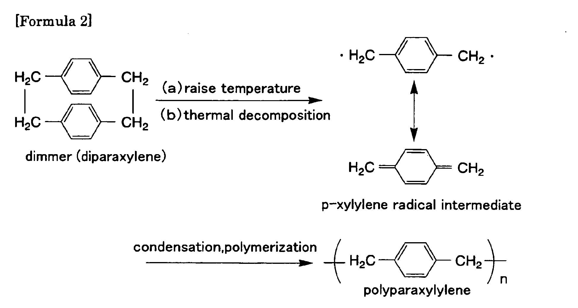
- This resin can be made radical by firstly thermal decomposing paraxylene at about 900°C as shown in the following chemical formula [Formula 1] in the presence of water, and quenched in benzene or toluene at 50°C to 250 °C.
- diparaxylene that is a cyclic dimer can be obtained.
- the obtained diparaxylene is heated about 600°C under low pressure so as to be thermally decomposed and formed into a paraxylylene radical gas intermediate.
- This gas is extremely reactive.
- this gas is introduced to the internal wall surface of the sound window, it is condensed and polymerized.
- the molecular weight of this polyparaxylylene is about 500,000.
- n denotes a repeating unit.
- the polyparaxylylene layer can be formed by vapor-depositing diparaxylene or the derivative thereof.
- the vapor deposition rate is generally in the range from 0.01 ⁇ m/min to 0.2 ⁇ m/min. According to the method using this vapor deposition process, an extremely thin layer can be formed and it is possible to prevent the sound propagation liquids from permeating and flowing out.
- a metal layer may be used.
- the metal layer may use a metal such as aluminum, gold, nickel, platinum, etc.
- a metal such as aluminum and gold can be used.
- the layer thickness of the metal layer is preferably 0.1 ⁇ m to 30 ⁇ nm because an excellent property of inhibiting liquid permeation is provided and the film formation is easy.
- the metal layer can be formed by, for example, a vapor deposition method. Furthermore, the metal layer may be formed by an attachment of a metal thin film. Thus, it is possible to form a thin film layer and to prevent the sound propagation liquid from permeating and flowing out.
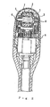
- FIG. 1 is a cross-sectional view showing one example of a structure of the ultrasonic probe according to the present invention.
- This ultrasonic probe is an intracorporeal insertion type probe used for an ultrasonic diagnosis. A part of this probe is inserted into the body cavity of a subject and ultrasonic scanning is carried out in the body cavity.
- This ultrasonic probe includes an inserting portion 100 to be inserted into the body cavity and a grip portion 200 held by an operator outside of the body.
- the insertion portion 100 includes a storage portion 10 disposed at the tip portion thereof, and a rod portion 20 for locating the storage portion 10 at the desirable portion in the body cavity.
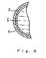
- the storage portion 10 is constructed in a way in which a sound window 4 and a frame 8 are connected. Inside the storage portion 10, an ultrasonic element unit is stored. Note here that in Figure 1 , for simplification, the interior structure of the storage portion 10 is simplified. Figure 2 is an enlarged cross-sectional view showing a detailed interior structure of the storage portion 10.
- the sound window 4 is not particularly limited. Those conventionally used may be used. However, it is preferable to use poly(methyl pentene-1) having a thickness of about 1 to 3 mm. It is advantageous because with this thickness, it is possible to avoid distortion of the extracted image since the sound window 4 is less distorted when it is pushed toward the body surface and because this thickness permits the ultrasonic attenuation.
- the barrier layer 3 is a polyparaxylylene layer having a thickness of 5 ⁇ m. This polyparaxylylene layer, as mentioned above, can be formed efficiently, for example, by vapor-depositing "Parylene” (a product manufactured by Three Bond Co., Ltd.).
- the film thickness of the polyparaxylylene layer is thick, or the window has a simple shape
- an attachment method can be employed.
- the barrier layer 3 a vapor-deposited film or attached film made of aluminum, gold, etc. can also be used.
- a degassed sound propagation liquid 5 is charged inside the sound window 4 of the storage portion 10.
- the sound propagation liquid 5 for example, physiological saline can be used.
- a frame 8 is provided with a through hole to which a pipe 9 is linked.
- the pipe 9 extends toward the grip portion 200 by way of a rod portion 20.
- the sound propagation liquid 5 also is charged in this pipe 9.
- the inside of the sound window 4 is configured so that the sound propagation liquid 5 is in communication to a reserve tank 12 via this pipe 9.
- the reserve tank 12 will be described later.
- the ultrasonic element unit includes an oscillator 2 and a rotation mechanism portion for holding and rotating the oscillator 2. Furthermore, a surface for transmitting and receiving ultrasonic waves of the oscillator 2 is provided with a sound lens 7.
- the rotation mechanism portion may be, for example, a spontaneous rotation type motor and includes a rotor 1 on which the oscillator 2 is mounted, a bracket 6 that rotatably supports this rotor and a rotation driving source (magnet) for providing the rotor 1 with a rotation power.
- a rotation mechanism portion allows the oscillator 2 to rotate along with the rotation of the rotor 1.
- a plurality of signal lines for transmitting and receiving electric signals for driving the oscillator 2 and the rotation mechanism portion are led out. These lead lines are introduced into the grip portion 200 via the rod portion 20.
- the grip portion 200 contains a reserve tank 12 in which the sound propagation liquid 5 is charged.
- This reserve tank 12 absorbs the change in the internal pressure inside the sound window 4 due to the temperature change and maintains the operation pressure.
- This reserve tank 12 is linked to the pipe 9 via a nozzle 11 and configured so that the sound propagation liquid 5 is in communication to the sound window 4.
- the reserve tank 12 is formed of an elastic container capable of altering its volume in accordance with the charged amount when liquids are charged in the container.
- a barrier layer is formed.
- Furthemore preferably, also on the wall surface of the pipe 9 connecting the storage portion 10 and the reserve tank 12, similarly, a barrier layer is formed.
- a cable 300 is led out.
- the ultrasonic probe is connected to the ultrasonic diagnostic equipment via this cable 300.
- an ultrasonic probe is located so as to drive a rotation mechanism portion and to rotate the rotor 1.
- the oscillator 2 mounted on the rotor 1 starts rotational movement.
- electric signals (transmitted signals) from the ultrasonic diagnostic equipment are transmitted to the oscillator 2.
- These transmitted signals are converted into ultrasonic waves and propagate in the sound propagation liquid 5, permeate the sound window 4 and are transmitted to the subject.
- These ultrasonic waves are reflected from the subject.
- a part of the reflected waves are received by the oscillator 2 and converted into ultrasonic signals (received signal) and sent to the ultrasonic diagnostic equipment.
- the received signals are converted into image data in the ultrasonic diagnostic equipment.
- the barrier layer 3 on the internal surface of the sound window 4, it is possible to suppress filtration or permeation of the sound propagation liquid 5 into the sound window 4 and to decrease the change in pressure of the sound propagation liquid 5. Therefore, the change in the internal pressure inside the sound window 4 can be reduced and the shape thereof can be maintained. Furthermore, since a sufficient amount of sound propagation liquid 5 is always charged, propagation of ultrasonic waves can be carried out with high fidelity.
- the barrier layer 3 is provided on the interanl wall surface of the sound window 4.
- the barrier layer 3 may be provided on the external surface of the sound window.
- the same effect can be obtained if the barrier layer 3 is provided between layers.
- a part of the barrier layer may be provided with a through hole.
- the barrier layer is formed of a polyparaxylylene layer or a metal layer
- the barrier layer may be formed of a multilayer including a polyparaxylylene layer and a metal layer.
- becouse the pemeation rate of the sound propagation liquid through resin varies depending upon the type of the sound propagation liquid, the other film having a property corresponding the type of sound propagation liquid may be provided.
- the ultrasonic probe of the present invention by providing a barrier layer on the internal wall of the sound window, it is possible to provide an ultrasonic probe in which filtration and permeation of the sound propagation liquids to materials of the sound window.
- Such ultrasonic probes can be used for, for example, an ultrasonic diagnostic equipment, and the like.
Landscapes
- Health & Medical Sciences (AREA)
- Life Sciences & Earth Sciences (AREA)
- Physics & Mathematics (AREA)
- Engineering & Computer Science (AREA)
- Pathology (AREA)
- General Health & Medical Sciences (AREA)
- Medical Informatics (AREA)
- Veterinary Medicine (AREA)
- Biophysics (AREA)
- Radiology & Medical Imaging (AREA)
- Biomedical Technology (AREA)
- Heart & Thoracic Surgery (AREA)
- Nuclear Medicine, Radiotherapy & Molecular Imaging (AREA)
- Molecular Biology (AREA)
- Surgery (AREA)
- Animal Behavior & Ethology (AREA)
- Public Health (AREA)
- Acoustics & Sound (AREA)
- Signal Processing (AREA)
- Chemical & Material Sciences (AREA)
- Analytical Chemistry (AREA)
- Biochemistry (AREA)
- General Physics & Mathematics (AREA)
- Immunology (AREA)
- Ultra Sonic Daignosis Equipment (AREA)
- Transducers For Ultrasonic Waves (AREA)
- Investigating Or Analyzing Materials By The Use Of Ultrasonic Waves (AREA)
Abstract
Description
- The present invention relates to an ultrasonic probe. More specifically, it relates to an ultrasonic probe comprising an ultrasonic element, a sound window enclosing the ultrasonic element and a sound propagation liquid charged in the sound window.
- An ultrasonic probe is used for a fish finder, an ultrasonic diagnostic equipment used with living bodies, or the like. As the ultrasonic equipment used for an ultrasonic diagnostic equipment, an ultrasonic probe including an ultrasonic element for transmitting and receiving ultrasonic waves, a sound window enclosing the ultrasonic element and a sound propagation liquid having a sound impedance, which is approximate to that of a living body, charged in the sound window is well known (see, for example,
JP02 (1990)-98341 A - Such ultrasonic probes use a resin for a material that constitutes the sound window, from the viewpoint of the sound properties. Therefore, since the water absorption rate is different depending upon the used resins due to the influence of the molecular structure, etc., after a long time of use, depending upon the kinds, temperature and resin materials, etc., of the sound propagation liquid, the sound propagation liquid may intrude into a resin that constitutes the sound window, or further may penetrate the sound window and leak toward the outside. As a result, the pressure inside the sound window is lowered so as to become lower than the external pressure, so that an air may penetrate the resin that constitutes the sound window and the air may be a contaminant inside the sound window. When air bubble contaminates into the sound window, it acts as a reflector with respect to the ultrasonic waves, thus inhibiting the transmittance and receiving of the ultrasonic waves, which in turn may lead to the deterioration of ultrasonic diagnostic images. In order to suppress an occurrence of such air bubbles, in this kind of ultrasonic probes, a sound propagation liquid has to be refilled over time so as to maintain the pressure inside the sound window.
- Document
DE 197 42 294 A1 recites a sound generator and/or sound receiver having a barrier layer provided to prevent external liquid from permeating the oscillator. - Patent document
US 5,550,790 recites an acoustic transducer having a barrier layer that is provided on the exterior of teh acoustic window in order to prevent an external liquid from permeating the transducer. - Patent document
US 5,762,066 recites a structure of arranging at a grip portion a distal region and a reservoir where a fluid moves in accordance with the change in volume when the transducer is moved for linear scanning. With this structure, change in the pressure of the fluid can be suppressed. - Patent document
US 4,517,985 recites that the acoustic window is formed of a soft membrane, and that a bladder is provided with a spring in order to suppress increase of the liquid pressure due to the external pressure. - With the foregoing in mind, it is therefore an object of the present invention to provide an ultrasonic probe capable of suppressing the permeation of the sound propagation liquid from the sound window and maintaining the presusre inside the sound window.
- In order to achieve the above-mentioned object, the ultrasonic probe of the present invention includes an ultrasonic element made of piezoelectric substance for transmitting and receiving ultrasonic waves, a sound window enclosing the element and an ultrasonic wave propagation liquid charged in the sound window, wherein the sound window is provided with a barrier layer capable of inhibiting the permeation of liquids and gases.
- For the above-mentioned barrier layer, for exmaple, a layer including at least one of a polyparaxylylene layer and a metal layer can be used.
-
-
Figure. 1 is a schematic cross-sectional view showing one example of an ultrasonic probe of the present invention. -
Figure 2 is an enlarged cross-sectional view showing a storage portion of the above-mentioned ultrasonic probe. -
Figure 3 is an enlarged cross-sectional view showing a sound window of the above-mentioned ultrasonic probe. - As mentioned above, the ultrasonic probe of the present invention includes an ultrasonic element for transmitting and receiving ultrasonic waves, a sound window enclosing the ultrasonic element and an ultrasonic wave propagation liquid charged in the sound window. In the sound window, a barrier layer capable of inhibiting the permeation of liquids and gases is formed. With such a configuraiton, it is possible to suppress the permeation of the sound propagation liquids from the sound window and to suppress the reduction of the amount of liquids. As a result, the pressure in the sound window can be matintained.
- It is preferable that the barrier layer is formed on an internal wall surface of the sound window.
- As the barrier layer, polyparaxylylene or the derivative thereof can be used. As the polyparaxylylene derivative, polyparaxylylene with each aromatic ring having at least one hydrogen substituted with, for example, chlorine, bromine, fluorine, an alkyl group, an amino group, etc. can be used. The layer thickness of the polyparaxylylene layer is preferably in the range from 0.1 µm to 500 µm and more preferably 1 µm to 100 µm because the inhibiting property is excellent and the film formation is easy.
- The polyparaxylylene layer can be formed as a polyparaxylylene resin layer by a chemical vapor deposition of diparaxylylene or the derivative thereof. As diparaxylylene, for example, "Parylene" manufactured by Three Bond Co., Ltd. can be employed. Furthermore, as the diparaxylylene derivative, diparaxylylene with each aromatic ring having at least one hydrogen substituted with, for example, chlorine, bromine, fluorine, an alkyl group, an amino group, etc. can be used.
- One example of the method for forming this polyparaxylylene resin layer will be described in more detail. This resin can be made radical by firstly thermal decomposing paraxylene at about 900°C as shown in the following chemical formula [Formula 1] in the presence of water, and quenched in benzene or toluene at 50°C to 250 °C. Thus, diparaxylene that is a cyclic dimer can be obtained.

- The obtained diparaxylene is heated about 600°C under low pressure so as to be thermally decomposed and formed into a paraxylylene radical gas intermediate. This gas is extremely reactive. When this gas is introduced to the internal wall surface of the sound window, it is condensed and polymerized. Thus, a layer form of polyparaxylylene is obtained. The molecular weight of this polyparaxylylene is about 500,000. Note here that in Formula 2, n denotes a repeating unit.
- Thus, the polyparaxylylene layer can be formed by vapor-depositing diparaxylene or the derivative thereof. The vapor deposition rate is generally in the range from 0.01 µm/min to 0.2 µm/min. According to the method using this vapor deposition process, an extremely thin layer can be formed and it is possible to prevent the sound propagation liquids from permeating and flowing out.
- As the barrier layer, a metal layer may be used. In this case, the metal layer may use a metal such as aluminum, gold, nickel, platinum, etc. Preferably, a metal such as aluminum and gold can be used. Furthermore, the layer thickness of the metal layer is preferably 0.1 µm to 30 µnm because an excellent property of inhibiting liquid permeation is provided and the film formation is easy.
- The metal layer can be formed by, for example, a vapor deposition method. Furthermore, the metal layer may be formed by an attachment of a metal thin film. Thus, it is possible to form a thin film layer and to prevent the sound propagation liquid from permeating and flowing out.
- Hereinafter, the present invention will be described by way of a preferable embodiment and with reference to drawings.
Figure 1 is a cross-sectional view showing one example of a structure of the ultrasonic probe according to the present invention. This ultrasonic probe is an intracorporeal insertion type probe used for an ultrasonic diagnosis. A part of this probe is inserted into the body cavity of a subject and ultrasonic scanning is carried out in the body cavity. This ultrasonic probe includes aninserting portion 100 to be inserted into the body cavity and agrip portion 200 held by an operator outside of the body. - The
insertion portion 100 includes astorage portion 10 disposed at the tip portion thereof, and arod portion 20 for locating thestorage portion 10 at the desirable portion in the body cavity. Thestorage portion 10 is constructed in a way in which asound window 4 and aframe 8 are connected. Inside thestorage portion 10, an ultrasonic element unit is stored. Note here that inFigure 1 , for simplification, the interior structure of thestorage portion 10 is simplified.Figure 2 is an enlarged cross-sectional view showing a detailed interior structure of thestorage portion 10. - The
sound window 4 is not particularly limited. Those conventionally used may be used. However, it is preferable to use poly(methyl pentene-1) having a thickness of about 1 to 3 mm. It is advantageous because with this thickness, it is possible to avoid distortion of the extracted image since thesound window 4 is less distorted when it is pushed toward the body surface and because this thickness permits the ultrasonic attenuation. - As mentioned above, on the internal wall surface of the
sound window 4, abarrier layer 3 is formed. As shown inFigure 3 , it is preferable that thebarrier layer 3 is formed in close contact with the internal wall surface of thesound window 4. When such asound window 4 having thebarrier layer 3 is used in the ordinary room environment, since the reduction of liquid amount due to the permeation of liquids is extremely small and little drop in the internal pressure occurs, a stable shape can be secured. In this embodiment, thebarrier layer 3 is a polyparaxylylene layer having a thickness of 5 µm. This polyparaxylylene layer, as mentioned above, can be formed efficiently, for example, by vapor-depositing "Parylene" (a product manufactured by Three Bond Co., Ltd.). Furthermore, in a case where the film thickness of the polyparaxylylene layer is thick, or the window has a simple shape, an attachment method can be employed. Furthermore, as thebarrier layer 3, a vapor-deposited film or attached film made of aluminum, gold, etc. can also be used. - Inside the
sound window 4 of thestorage portion 10, a degassedsound propagation liquid 5 is charged. As thesound propagation liquid 5, for example, physiological saline can be used. Furthermore, aframe 8 is provided with a through hole to which a pipe 9 is linked. The pipe 9 extends toward thegrip portion 200 by way of arod portion 20. Thesound propagation liquid 5 also is charged in this pipe 9. Thus, the inside of thesound window 4 is configured so that thesound propagation liquid 5 is in communication to areserve tank 12 via this pipe 9. Thereserve tank 12 will be described later. - The ultrasonic element unit includes an
oscillator 2 and a rotation mechanism portion for holding and rotating theoscillator 2. Furthermore, a surface for transmitting and receiving ultrasonic waves of theoscillator 2 is provided with asound lens 7. The rotation mechanism portion may be, for example, a spontaneous rotation type motor and includes a rotor 1 on which theoscillator 2 is mounted, abracket 6 that rotatably supports this rotor and a rotation driving source (magnet) for providing the rotor 1 with a rotation power. Such a rotation mechanism portion allows theoscillator 2 to rotate along with the rotation of the rotor 1. Thus, it is possible to realize mechanical scanning with a circular orbit of the ultrasonic waves. Furthermore, from the ultrasonic element unit, a plurality of signal lines for transmitting and receiving electric signals for driving theoscillator 2 and the rotation mechanism portion are led out. These lead lines are introduced into thegrip portion 200 via therod portion 20. - The
grip portion 200 contains areserve tank 12 in which thesound propagation liquid 5 is charged. Thisreserve tank 12 absorbs the change in the internal pressure inside thesound window 4 due to the temperature change and maintains the operation pressure. Thisreserve tank 12 is linked to the pipe 9 via anozzle 11 and configured so that thesound propagation liquid 5 is in communication to thesound window 4. Thereserve tank 12 is formed of an elastic container capable of altering its volume in accordance with the charged amount when liquids are charged in the container. - In this embodiment, preferably, also on the wall surface of the
reserve tank 12, similar to thesound window 4, a barrier layer is formed. Furthemore, preferably, also on the wall surface of the pipe 9 connecting thestorage portion 10 and thereserve tank 12, similarly, a barrier layer is formed. - Furthemore, from the
grip portion 200, acable 300 is led out. The ultrasonic probe is connected to the ultrasonic diagnostic equipment via thiscable 300. - Next, an operation of the above-mentieond ultrasonic probe will be described.
- First of all, in the vicinity of a subject, an ultrasonic probe is located so as to drive a rotation mechanism portion and to rotate the rotor 1. Thereby, the
oscillator 2 mounted on the rotor 1 starts rotational movement. Next, electric signals (transmitted signals) from the ultrasonic diagnostic equipment are transmitted to theoscillator 2. These transmitted signals are converted into ultrasonic waves and propagate in thesound propagation liquid 5, permeate thesound window 4 and are transmitted to the subject. These ultrasonic waves are reflected from the subject. A part of the reflected waves are received by theoscillator 2 and converted into ultrasonic signals (received signal) and sent to the ultrasonic diagnostic equipment. The received signals are converted into image data in the ultrasonic diagnostic equipment. By carrying out this operation for transmitting and receiving ultrasonic waves while rotating repeatedly, scanning of the ultrasonic waves can be carried out. - According to this embodiment, by providing the
barrier layer 3 on the internal surface of thesound window 4, it is possible to suppress filtration or permeation of thesound propagation liquid 5 into thesound window 4 and to decrease the change in pressure of thesound propagation liquid 5. Therefore, the change in the internal pressure inside thesound window 4 can be reduced and the shape thereof can be maintained. Furthermore, since a sufficient amount ofsound propagation liquid 5 is always charged, propagation of ultrasonic waves can be carried out with high fidelity. - Note here that in the above description, the
barrier layer 3 is provided on the interanl wall surface of thesound window 4. However, thebarrier layer 3 may be provided on the external surface of the sound window. Alternatively, in the case of the sound window configured of a plurality of layers, the same effect can be obtained if thebarrier layer 3 is provided between layers. In this case, in order to improve the adhesion between the layers constituting the window, a part of the barrier layer may be provided with a through hole. - Furthermore, in the description, an example of the mechanical scannig in which the oscillator is rotated by a motor is described. The mechanical scanning method by the array type element in which a plulraity of oscillators are arranged may be employed.
- Furthermore, an example in which the barrier layer is formed of a polyparaxylylene layer or a metal layer is described, the barrier layer may be formed of a multilayer including a polyparaxylylene layer and a metal layer. Furthermore, becouse the pemeation rate of the sound propagation liquid through resin varies depending upon the type of the sound propagation liquid, the other film having a property corresponding the type of sound propagation liquid may be provided.
- As mentioned above, according to the ultrasonic probe of the present invention, by providing a barrier layer on the internal wall of the sound window, it is possible to provide an ultrasonic probe in which filtration and permeation of the sound propagation liquids to materials of the sound window. Such ultrasonic probes can be used for, for example, an ultrasonic diagnostic equipment, and the like.
Claims (7)
- An ultrasonic probe, comprising:an insertion portion (100) having a storage portion (10) disposed at a foremost end, the storage portion (10) comprising an ultrasonic element for transmitting and receiving ultrasonic waves, and a pressurized sound window (4) enclosing the ultrasonic element, wherein a sound propagation liquid (5) is charged in the sound window (4); anda barrier layer (3) provided on a wall surface of the sound window (4), wherein the barrier layer (3) is capable of inhibiting the permeation of liquids and gases,characterized by
a grip portion (200) attached to the insertion portion (100), the grip portion (200) comprising an elastic reserve tank (12);
wherein the sound window (4) is in communication with the elastic reserve tank (12);
wherein the barrier layer (3) is provided on an internal wall surface of the sound window (4); and
wherein the elastic reserve tank (12) absorbs changes of pressure of the charged sound propagation liquid (5) in the sound window (4) to maintain the pressure of the sound window (4). - The ultrasonic probe according to claim 1, wherein the barrier layer comprises at least one selected from a polyparaxylylene layer and a metal layer.
- The ultrasonic probe according to claim 2, wherein the barrier layer comprises a polyparaxylylene layer and the layer thickness of the polyparaxylylene layer is in the range from 0.1 µm to 500 µm.
- The ultrasonic probe according to claim 2, wherein the barrier layer comprises a polyparaxylylene layer and the polyparaxylylene layer is formed by vapor deposition of diparaxylylene or the derivative thereof.
- The ultrasonic probe according to claim 2, wherein the barrier layer comprises a metal layer and the metal layer comprises at least one selected from the group consisting of aluminum, gold, nickel and platinum.
- The ultrasonic probe according to claim 2, wherein the barrier layer comprises a metal layer and the thickness of the metal layer is in the range from 0.1 µm to 30 µm.
- The ultrasonic probe according to claim 1, wherein the barrier layer comprises a plurality of layers.
Applications Claiming Priority (3)
| Application Number | Priority Date | Filing Date | Title |
|---|---|---|---|
| JP2002115355A JP2003309890A (en) | 2002-04-17 | 2002-04-17 | Ultrasonic probe |
| JP2002115355 | 2002-04-17 | ||
| PCT/JP2003/004740 WO2003088705A1 (en) | 2002-04-17 | 2003-04-15 | Ultrasonic probe |
Publications (3)
| Publication Number | Publication Date |
|---|---|
| EP1501331A1 EP1501331A1 (en) | 2005-01-26 |
| EP1501331A4 EP1501331A4 (en) | 2008-12-17 |
| EP1501331B1 true EP1501331B1 (en) | 2011-06-22 |
Family
ID=29243421
Family Applications (1)
| Application Number | Title | Priority Date | Filing Date |
|---|---|---|---|
| EP03717580A Expired - Fee Related EP1501331B1 (en) | 2002-04-17 | 2003-04-15 | Ultrasonic probe |
Country Status (7)
| Country | Link |
|---|---|
| US (1) | US7833162B2 (en) |
| EP (1) | EP1501331B1 (en) |
| JP (1) | JP2003309890A (en) |
| KR (1) | KR100656299B1 (en) |
| CN (1) | CN100588285C (en) |
| CA (1) | CA2482822A1 (en) |
| WO (1) | WO2003088705A1 (en) |
Cited By (12)
| Publication number | Priority date | Publication date | Assignee | Title |
|---|---|---|---|---|
| US9283409B2 (en) | 2004-10-06 | 2016-03-15 | Guided Therapy Systems, Llc | Energy based fat reduction |
| US9283410B2 (en) | 2004-10-06 | 2016-03-15 | Guided Therapy Systems, L.L.C. | System and method for fat and cellulite reduction |
| US9320537B2 (en) | 2004-10-06 | 2016-04-26 | Guided Therapy Systems, Llc | Methods for noninvasive skin tightening |
| US9421029B2 (en) | 2004-10-06 | 2016-08-23 | Guided Therapy Systems, Llc | Energy based hyperhidrosis treatment |
| US9427601B2 (en) | 2004-10-06 | 2016-08-30 | Guided Therapy Systems, Llc | Methods for face and neck lifts |
| US9427600B2 (en) | 2004-10-06 | 2016-08-30 | Guided Therapy Systems, L.L.C. | Systems for treating skin laxity |
| US9440096B2 (en) | 2004-10-06 | 2016-09-13 | Guided Therapy Systems, Llc | Method and system for treating stretch marks |
| US9510802B2 (en) | 2012-09-21 | 2016-12-06 | Guided Therapy Systems, Llc | Reflective ultrasound technology for dermatological treatments |
| US10010724B2 (en) | 2004-10-06 | 2018-07-03 | Guided Therapy Systems, L.L.C. | Ultrasound probe for treating skin laxity |
| US10010726B2 (en) | 2004-10-06 | 2018-07-03 | Guided Therapy Systems, Llc | Ultrasound probe for treatment of skin |
| US11590370B2 (en) | 2004-09-24 | 2023-02-28 | Guided Therapy Systems, Llc | Rejuvenating skin by heating tissue for cosmetic treatment of the face and body |
| US11969609B2 (en) | 2022-12-05 | 2024-04-30 | Ulthera, Inc. | Devices and methods for multi-focus ultrasound therapy |
Families Citing this family (29)
| Publication number | Priority date | Publication date | Assignee | Title |
|---|---|---|---|---|
| WO2005096267A1 (en) * | 2004-04-02 | 2005-10-13 | Koninklijke Philips Electronics, N.V. | Intracavity probe with continuous shielding of acoustic window |
| US8690778B2 (en) | 2004-10-06 | 2014-04-08 | Guided Therapy Systems, Llc | Energy-based tissue tightening |
| US11235179B2 (en) | 2004-10-06 | 2022-02-01 | Guided Therapy Systems, Llc | Energy based skin gland treatment |
| US11883688B2 (en) | 2004-10-06 | 2024-01-30 | Guided Therapy Systems, Llc | Energy based fat reduction |
| US11207548B2 (en) | 2004-10-07 | 2021-12-28 | Guided Therapy Systems, L.L.C. | Ultrasound probe for treating skin laxity |
| US11724133B2 (en) | 2004-10-07 | 2023-08-15 | Guided Therapy Systems, Llc | Ultrasound probe for treatment of skin |
| ITFI20050170A1 (en) * | 2005-07-29 | 2007-01-30 | Leone Spa | PROCEDURE FOR THE MANUFACTURE OF ORTHODONTIC DEVICES AND ORTHODONTIC DEVICE |
| JP4695479B2 (en) * | 2005-09-30 | 2011-06-08 | 富士フイルム株式会社 | Ultrasonic generator |
| WO2008018054A2 (en) * | 2006-08-08 | 2008-02-14 | Keter Medical Ltd. | Imaging system |
| CN100574828C (en) * | 2006-08-24 | 2009-12-30 | 重庆融海超声医学工程研究中心有限公司 | A kind of apparatus for ultrasonic therapeutic treatment and contain the supersonic therapeutic system of this apparatus for ultrasonic therapeutic treatment |
| JP2008263419A (en) * | 2007-04-12 | 2008-10-30 | Matsushita Electric Ind Co Ltd | Acoustic matching body, ultrasonic transmitter/receiver and ultrasonic flow rate flow meter |
| JP2010005374A (en) * | 2008-05-28 | 2010-01-14 | Nippon Dempa Kogyo Co Ltd | Minor axis motion type ultrasonic probe |
| CN104545998B (en) | 2008-06-06 | 2020-07-14 | 奥赛拉公司 | System and method for cosmetic treatment and imaging |
| US8690783B2 (en) * | 2010-05-21 | 2014-04-08 | Misonix, Incorporated | Ultrasonic transducer assembly |
| EP2742870A4 (en) * | 2011-08-08 | 2015-03-04 | Konica Minolta Inc | Ultrasound probe |
| US9814444B2 (en) * | 2012-10-12 | 2017-11-14 | Muffin Incorporated | Feedback/registration mechanism for ultrasound devices |
| CN204017181U (en) | 2013-03-08 | 2014-12-17 | 奥赛拉公司 | Aesthstic imaging and processing system, multifocal processing system and perform the system of aesthetic procedure |
| JP2015100381A (en) * | 2013-11-21 | 2015-06-04 | セイコーエプソン株式会社 | Ultrasonic gel sheet assembly |
| SG11201608691YA (en) | 2014-04-18 | 2016-11-29 | Ulthera Inc | Band transducer ultrasound therapy |
| US11566932B2 (en) * | 2014-07-09 | 2023-01-31 | Husky Corporation | Sonic monitor system for a tank |
| JP2017046945A (en) * | 2015-09-02 | 2017-03-09 | コニカミノルタ株式会社 | Ultrasound probe and ultrasound diagnosis apparatus |
| US10161919B2 (en) * | 2016-10-25 | 2018-12-25 | Fisher Controls International Llc | Acoustic emission sensors with integral acoustic generators |
| ES2939604T3 (en) | 2016-01-18 | 2023-04-25 | Ulthera Inc | Compact ultrasonic device having an annular ultrasonic array peripherally electrically connected to a flexible printed circuit board |
| JP6880953B2 (en) * | 2016-04-12 | 2021-06-02 | コニカミノルタ株式会社 | Ultrasonic probe |
| US10249409B2 (en) * | 2016-06-21 | 2019-04-02 | Schlumberger Technology Corporation | Coated conductors |
| US11241218B2 (en) | 2016-08-16 | 2022-02-08 | Ulthera, Inc. | Systems and methods for cosmetic ultrasound treatment of skin |
| JP6852366B2 (en) * | 2016-11-29 | 2021-03-31 | セイコーエプソン株式会社 | Ultrasonic device and ultrasonic device |
| WO2018125185A1 (en) * | 2016-12-30 | 2018-07-05 | Intel Corporation | Packaging for ultrasonic transducers |
| US11944849B2 (en) | 2018-02-20 | 2024-04-02 | Ulthera, Inc. | Systems and methods for combined cosmetic treatment of cellulite with ultrasound |
Citations (2)
| Publication number | Priority date | Publication date | Assignee | Title |
|---|---|---|---|---|
| US4517985A (en) * | 1982-06-01 | 1985-05-21 | Diasonics, Inc. | Neonate ultrasonic scanner |
| US5762066A (en) * | 1992-02-21 | 1998-06-09 | Ths International, Inc. | Multifaceted ultrasound transducer probe system and methods for its use |
Family Cites Families (21)
| Publication number | Priority date | Publication date | Assignee | Title |
|---|---|---|---|---|
| JPS6036565B2 (en) | 1980-02-20 | 1985-08-21 | 日本電信電話株式会社 | Positioning jig for permanent optical fiber connection |
| JPS61119249A (en) | 1984-11-14 | 1986-06-06 | 松下電器産業株式会社 | Ultrasonic probe |
| US5105818A (en) * | 1987-04-10 | 1992-04-21 | Cardiometric, Inc. | Apparatus, system and method for measuring spatial average velocity and/or volumetric flow of blood in a vessel and screw joint for use therewith |
| EP0286359A3 (en) | 1987-04-10 | 1991-12-11 | Cardiometrics, Inc. | Apparatus, system and method for measuring volumetric flow of blood in a vessel |
| US4967753A (en) | 1987-04-10 | 1990-11-06 | Cardiometrics, Inc. | Apparatus, system and method for measuring spatial average velocity and/or volumetric flow of blood in a vessel |
| US5372138A (en) * | 1988-03-21 | 1994-12-13 | Boston Scientific Corporation | Acousting imaging catheters and the like |
| JPH0298341A (en) | 1988-10-04 | 1990-04-10 | Fuji Electric Co Ltd | Ultrasonic probe |
| JP2761394B2 (en) | 1989-01-19 | 1998-06-04 | オリンパス光学工業株式会社 | Endoscopic ultrasound diagnostic equipment |
| JP2852076B2 (en) | 1989-07-04 | 1999-01-27 | オリンパス光学工業株式会社 | Hyperthermia probe |
| JPH0722583B2 (en) | 1990-04-05 | 1995-03-15 | 松下電器産業株式会社 | Mechanical scanning ultrasonic probe |
| US5469853A (en) * | 1992-12-11 | 1995-11-28 | Tetrad Corporation | Bendable ultrasonic probe and sheath for use therewith |
| JPH06209937A (en) | 1993-01-21 | 1994-08-02 | Olympus Optical Co Ltd | Ultrasonic probe |
| US5550790A (en) | 1995-02-10 | 1996-08-27 | Kistler-Morse Corporation | Acoustic transducer for level measurement in corrosive chemical environments |
| US5640961A (en) * | 1995-09-25 | 1997-06-24 | Hewlett-Packard Company | Device with aspherical compensation for focusing ultrasound |
| JPH10262974A (en) * | 1997-03-26 | 1998-10-06 | Olympus Optical Co Ltd | Ultrasonic endoscope |
| DE19742294A1 (en) | 1997-09-25 | 1999-04-01 | Elster Produktion Gmbh | Sound receiver or producer |
| US5897504A (en) * | 1997-12-12 | 1999-04-27 | The Whitaker Corporation | Ultrasound imaging probe assembly |
| FR2773460B1 (en) * | 1998-01-14 | 2000-06-09 | 2 Mt Materiel Medical Tech | ECHOGRAPHY PROBE AND ACCESSORIES |
| US5997481A (en) * | 1998-02-17 | 1999-12-07 | Ultra Sound Probe Covers, Llc | Probe cover with deformable membrane gel reservoir |
| JPH11285496A (en) | 1998-04-01 | 1999-10-19 | Olympus Optical Co Ltd | Ultrasonic probe |
| JP2002078673A (en) * | 2000-09-06 | 2002-03-19 | Asahi Optical Co Ltd | Endoscope |
-
2002
- 2002-04-17 JP JP2002115355A patent/JP2003309890A/en active Pending
-
2003
- 2003-04-15 CN CN03808619A patent/CN100588285C/en not_active Expired - Fee Related
- 2003-04-15 CA CA002482822A patent/CA2482822A1/en not_active Abandoned
- 2003-04-15 WO PCT/JP2003/004740 patent/WO2003088705A1/en active Application Filing
- 2003-04-15 EP EP03717580A patent/EP1501331B1/en not_active Expired - Fee Related
- 2003-04-15 US US10/511,478 patent/US7833162B2/en not_active Expired - Fee Related
- 2003-04-15 KR KR1020047016624A patent/KR100656299B1/en not_active IP Right Cessation
Patent Citations (2)
| Publication number | Priority date | Publication date | Assignee | Title |
|---|---|---|---|---|
| US4517985A (en) * | 1982-06-01 | 1985-05-21 | Diasonics, Inc. | Neonate ultrasonic scanner |
| US5762066A (en) * | 1992-02-21 | 1998-06-09 | Ths International, Inc. | Multifaceted ultrasound transducer probe system and methods for its use |
Cited By (24)
| Publication number | Priority date | Publication date | Assignee | Title |
|---|---|---|---|---|
| US10328289B2 (en) | 2004-09-24 | 2019-06-25 | Guided Therapy Systems, Llc | Rejuvenating skin by heating tissue for cosmetic treatment of the face and body |
| US11590370B2 (en) | 2004-09-24 | 2023-02-28 | Guided Therapy Systems, Llc | Rejuvenating skin by heating tissue for cosmetic treatment of the face and body |
| US10010721B2 (en) | 2004-10-06 | 2018-07-03 | Guided Therapy Systems, L.L.C. | Energy based fat reduction |
| US9427601B2 (en) | 2004-10-06 | 2016-08-30 | Guided Therapy Systems, Llc | Methods for face and neck lifts |
| US10010725B2 (en) | 2004-10-06 | 2018-07-03 | Guided Therapy Systems, Llc | Ultrasound probe for fat and cellulite reduction |
| US9427600B2 (en) | 2004-10-06 | 2016-08-30 | Guided Therapy Systems, L.L.C. | Systems for treating skin laxity |
| US9440096B2 (en) | 2004-10-06 | 2016-09-13 | Guided Therapy Systems, Llc | Method and system for treating stretch marks |
| US9283409B2 (en) | 2004-10-06 | 2016-03-15 | Guided Therapy Systems, Llc | Energy based fat reduction |
| US9522290B2 (en) | 2004-10-06 | 2016-12-20 | Guided Therapy Systems, Llc | System and method for fat and cellulite reduction |
| US9533175B2 (en) | 2004-10-06 | 2017-01-03 | Guided Therapy Systems, Llc | Energy based fat reduction |
| US10010726B2 (en) | 2004-10-06 | 2018-07-03 | Guided Therapy Systems, Llc | Ultrasound probe for treatment of skin |
| US10010724B2 (en) | 2004-10-06 | 2018-07-03 | Guided Therapy Systems, L.L.C. | Ultrasound probe for treating skin laxity |
| US9283410B2 (en) | 2004-10-06 | 2016-03-15 | Guided Therapy Systems, L.L.C. | System and method for fat and cellulite reduction |
| US9421029B2 (en) | 2004-10-06 | 2016-08-23 | Guided Therapy Systems, Llc | Energy based hyperhidrosis treatment |
| US9974982B2 (en) | 2004-10-06 | 2018-05-22 | Guided Therapy Systems, Llc | System and method for noninvasive skin tightening |
| US10046182B2 (en) | 2004-10-06 | 2018-08-14 | Guided Therapy Systems, Llc | Methods for face and neck lifts |
| US10046181B2 (en) | 2004-10-06 | 2018-08-14 | Guided Therapy Systems, Llc | Energy based hyperhidrosis treatment |
| US10238894B2 (en) | 2004-10-06 | 2019-03-26 | Guided Therapy Systems, L.L.C. | Energy based fat reduction |
| US10245450B2 (en) | 2004-10-06 | 2019-04-02 | Guided Therapy Systems, Llc | Ultrasound probe for fat and cellulite reduction |
| US10252086B2 (en) | 2004-10-06 | 2019-04-09 | Guided Therapy Systems, Llc | Ultrasound probe for treatment of skin |
| US10265550B2 (en) | 2004-10-06 | 2019-04-23 | Guided Therapy Systems, L.L.C. | Ultrasound probe for treating skin laxity |
| US9320537B2 (en) | 2004-10-06 | 2016-04-26 | Guided Therapy Systems, Llc | Methods for noninvasive skin tightening |
| US9510802B2 (en) | 2012-09-21 | 2016-12-06 | Guided Therapy Systems, Llc | Reflective ultrasound technology for dermatological treatments |
| US11969609B2 (en) | 2022-12-05 | 2024-04-30 | Ulthera, Inc. | Devices and methods for multi-focus ultrasound therapy |
Also Published As
| Publication number | Publication date |
|---|---|
| CN1647574A (en) | 2005-07-27 |
| US20050184624A1 (en) | 2005-08-25 |
| KR100656299B1 (en) | 2006-12-11 |
| EP1501331A1 (en) | 2005-01-26 |
| CN100588285C (en) | 2010-02-03 |
| US7833162B2 (en) | 2010-11-16 |
| JP2003309890A (en) | 2003-10-31 |
| CA2482822A1 (en) | 2003-10-23 |
| EP1501331A4 (en) | 2008-12-17 |
| KR20040103961A (en) | 2004-12-09 |
| WO2003088705A1 (en) | 2003-10-23 |
Similar Documents
| Publication | Publication Date | Title |
|---|---|---|
| EP1501331B1 (en) | Ultrasonic probe | |
| US8353839B2 (en) | Intracavity probe with continuous shielding of acoustic window | |
| US11141134B2 (en) | Focused rotational IVUS transducer using single crystal composite material | |
| EP1689299B1 (en) | Array transducer for 3d tilting probes | |
| CA2501647C (en) | High frequency high frame-rate ultrasound imaging system | |
| JP4004396B2 (en) | Ultrasonic transducer | |
| US7588540B2 (en) | Ultrasonic probe for scanning a volume | |
| JP2006502828A5 (en) | ||
| CA2182377C (en) | Acoustic window and septum for imaging catheters | |
| US8353838B2 (en) | Ultrasonic probe volume compensation system | |
| EP1738351A1 (en) | Ultrasound probe with multiple fluid chambers | |
| US20190015071A1 (en) | Ultrasonic probe | |
| WO2004086975A1 (en) | Ultrasonic probe | |
| FR2461486A1 (en) | Endoscope ultrasonic diagnostic device for scanning stomach interior - has pivoted ultrasonic transducer coupled to detector providing scanning angle | |
| JP2008306315A (en) | Ultrasonic wave echo transceiver | |
| JP2001327500A (en) | Ultrasonic probe | |
| JP2012000219A (en) | Backing material for ultrasonic probe, ultrasonic probe using the same, and ultrasonic medical image diagnostic apparatus | |
| JP6880953B2 (en) | Ultrasonic probe | |
| JPH0910214A (en) | Ultrasonic catheter | |
| JPH07308317A (en) | Ultrasonic probe | |
| JPH06277219A (en) | Medical ultrasonic converter assembly | |
| JP2009213785A (en) | Ultrasonic probe | |
| JP2000232979A (en) | Ultrasonic wave probe |
Legal Events
| Date | Code | Title | Description |
|---|---|---|---|
| PUAI | Public reference made under article 153(3) epc to a published international application that has entered the european phase |
Free format text: ORIGINAL CODE: 0009012 |
|
| 17P | Request for examination filed |
Effective date: 20041111 |
|
| AK | Designated contracting states |
Kind code of ref document: A1 Designated state(s): AT BE BG CH CY CZ DE DK EE ES FI FR GB GR HU IE IT LI LU MC NL PT RO SE SI SK TR |
|
| RAP1 | Party data changed (applicant data changed or rights of an application transferred) |
Owner name: PANASONIC CORPORATION |
|
| A4 | Supplementary search report drawn up and despatched |
Effective date: 20081118 |
|
| RIC1 | Information provided on ipc code assigned before grant |
Ipc: H04R 17/00 20060101ALI20081113BHEP Ipc: H04R 1/02 20060101ALI20081113BHEP Ipc: A61B 8/00 20060101AFI20081113BHEP |
|
| 17Q | First examination report despatched |
Effective date: 20090427 |
|
| GRAP | Despatch of communication of intention to grant a patent |
Free format text: ORIGINAL CODE: EPIDOSNIGR1 |
|
| GRAS | Grant fee paid |
Free format text: ORIGINAL CODE: EPIDOSNIGR3 |
|
| GRAA | (expected) grant |
Free format text: ORIGINAL CODE: 0009210 |
|
| AK | Designated contracting states |
Kind code of ref document: B1 Designated state(s): DE FR GB |
|
| REG | Reference to a national code |
Ref country code: GB Ref legal event code: FG4D |
|
| REG | Reference to a national code |
Ref country code: DE Ref legal event code: R096 Ref document number: 60337486 Country of ref document: DE Effective date: 20110811 |
|
| PLBE | No opposition filed within time limit |
Free format text: ORIGINAL CODE: 0009261 |
|
| STAA | Information on the status of an ep patent application or granted ep patent |
Free format text: STATUS: NO OPPOSITION FILED WITHIN TIME LIMIT |
|
| 26N | No opposition filed |
Effective date: 20120323 |
|
| REG | Reference to a national code |
Ref country code: DE Ref legal event code: R097 Ref document number: 60337486 Country of ref document: DE Effective date: 20120323 |
|
| REG | Reference to a national code |
Ref country code: DE Ref legal event code: R082 Ref document number: 60337486 Country of ref document: DE Representative=s name: PATENTANWAELTE HENKEL, BREUER & PARTNER, DE |
|
| REG | Reference to a national code |
Ref country code: DE Ref legal event code: R082 Ref document number: 60337486 Country of ref document: DE Representative=s name: PATENTANWAELTE HENKEL, BREUER & PARTNER, DE |
|
| REG | Reference to a national code |
Ref country code: GB Ref legal event code: 732E Free format text: REGISTERED BETWEEN 20140417 AND 20140423 |
|
| REG | Reference to a national code |
Ref country code: FR Ref legal event code: TP Owner name: KONICA MINOLTA, INC., JP Effective date: 20140428 |
|
| REG | Reference to a national code |
Ref country code: DE Ref legal event code: R081 Ref document number: 60337486 Country of ref document: DE Owner name: KONICA MINOLTA, INC., JP Free format text: FORMER OWNER: PANASONIC CORPORATION, KADOMA-SHI, JP Effective date: 20140506 Ref country code: DE Ref legal event code: R082 Ref document number: 60337486 Country of ref document: DE Representative=s name: PATENTANWAELTE HENKEL, BREUER & PARTNER, DE Effective date: 20140226 Ref country code: DE Ref legal event code: R082 Ref document number: 60337486 Country of ref document: DE Representative=s name: PATENTANWAELTE HENKEL, BREUER & PARTNER, DE Effective date: 20140506 Ref country code: DE Ref legal event code: R081 Ref document number: 60337486 Country of ref document: DE Owner name: KONICA MINOLTA, INC., JP Free format text: FORMER OWNER: MATSUSHITA ELECTRIC INDUSTRIAL CO., LTD., KADOMA-SHI, JP Effective date: 20110617 Ref country code: DE Ref legal event code: R081 Ref document number: 60337486 Country of ref document: DE Owner name: KONICA MINOLTA, INC., JP Free format text: FORMER OWNER: PANASONIC CORPORATION, KADOMA-SHI, OSAKA, JP Effective date: 20140506 Ref country code: DE Ref legal event code: R081 Ref document number: 60337486 Country of ref document: DE Owner name: KONICA MINOLTA, INC., JP Free format text: FORMER OWNER: MATSUSHITA ELECTRIC INDUSTRIAL CO., LTD., KADOMA-SHI, OSAKA, JP Effective date: 20110617 Ref country code: DE Ref legal event code: R082 Ref document number: 60337486 Country of ref document: DE Representative=s name: PATENTANWAELTE HENKEL, BREUER & PARTNER MBB, DE Effective date: 20140506 Ref country code: DE Ref legal event code: R082 Ref document number: 60337486 Country of ref document: DE Representative=s name: PATENTANWAELTE HENKEL, BREUER & PARTNER MBB, DE Effective date: 20140226 |
|
| PGFP | Annual fee paid to national office [announced via postgrant information from national office to epo] |
Ref country code: GB Payment date: 20140423 Year of fee payment: 12 |
|
| PGFP | Annual fee paid to national office [announced via postgrant information from national office to epo] |
Ref country code: FR Payment date: 20140424 Year of fee payment: 12 |
|
| GBPC | Gb: european patent ceased through non-payment of renewal fee |
Effective date: 20150415 |
|
| PG25 | Lapsed in a contracting state [announced via postgrant information from national office to epo] |
Ref country code: GB Free format text: LAPSE BECAUSE OF NON-PAYMENT OF DUE FEES Effective date: 20150415 |
|
| REG | Reference to a national code |
Ref country code: FR Ref legal event code: ST Effective date: 20151231 |
|
| PG25 | Lapsed in a contracting state [announced via postgrant information from national office to epo] |
Ref country code: FR Free format text: LAPSE BECAUSE OF NON-PAYMENT OF DUE FEES Effective date: 20150430 |
|
| PGFP | Annual fee paid to national office [announced via postgrant information from national office to epo] |
Ref country code: DE Payment date: 20190402 Year of fee payment: 17 |
|
| REG | Reference to a national code |
Ref country code: DE Ref legal event code: R119 Ref document number: 60337486 Country of ref document: DE |
|
| PG25 | Lapsed in a contracting state [announced via postgrant information from national office to epo] |
Ref country code: DE Free format text: LAPSE BECAUSE OF NON-PAYMENT OF DUE FEES Effective date: 20201103 |