EP1505758A1 - Method and apparatus for determining a shuffling pattern based on a minimum signal to noise ratio in a double space-time transmit diversity system - Google Patents
Method and apparatus for determining a shuffling pattern based on a minimum signal to noise ratio in a double space-time transmit diversity system Download PDFInfo
- Publication number
- EP1505758A1 EP1505758A1 EP04017012A EP04017012A EP1505758A1 EP 1505758 A1 EP1505758 A1 EP 1505758A1 EP 04017012 A EP04017012 A EP 04017012A EP 04017012 A EP04017012 A EP 04017012A EP 1505758 A1 EP1505758 A1 EP 1505758A1
- Authority
- EP
- European Patent Office
- Prior art keywords
- shuffling
- shuffling pattern
- pattern
- optimum
- channel
- Prior art date
- Legal status (The legal status is an assumption and is not a legal conclusion. Google has not performed a legal analysis and makes no representation as to the accuracy of the status listed.)
- Withdrawn
Links
Images


Classifications
-
- H—ELECTRICITY
- H04—ELECTRIC COMMUNICATION TECHNIQUE
- H04B—TRANSMISSION
- H04B7/00—Radio transmission systems, i.e. using radiation field
- H04B7/02—Diversity systems; Multi-antenna system, i.e. transmission or reception using multiple antennas
- H04B7/04—Diversity systems; Multi-antenna system, i.e. transmission or reception using multiple antennas using two or more spaced independent antennas
- H04B7/06—Diversity systems; Multi-antenna system, i.e. transmission or reception using multiple antennas using two or more spaced independent antennas at the transmitting station
-
- H—ELECTRICITY
- H04—ELECTRIC COMMUNICATION TECHNIQUE
- H04B—TRANSMISSION
- H04B7/00—Radio transmission systems, i.e. using radiation field
- H04B7/02—Diversity systems; Multi-antenna system, i.e. transmission or reception using multiple antennas
- H04B7/04—Diversity systems; Multi-antenna system, i.e. transmission or reception using multiple antennas using two or more spaced independent antennas
- H04B7/0413—MIMO systems
- H04B7/0417—Feedback systems
-
- H—ELECTRICITY
- H04—ELECTRIC COMMUNICATION TECHNIQUE
- H04B—TRANSMISSION
- H04B7/00—Radio transmission systems, i.e. using radiation field
- H04B7/02—Diversity systems; Multi-antenna system, i.e. transmission or reception using multiple antennas
- H04B7/04—Diversity systems; Multi-antenna system, i.e. transmission or reception using multiple antennas using two or more spaced independent antennas
- H04B7/06—Diversity systems; Multi-antenna system, i.e. transmission or reception using multiple antennas using two or more spaced independent antennas at the transmitting station
- H04B7/0602—Diversity systems; Multi-antenna system, i.e. transmission or reception using multiple antennas using two or more spaced independent antennas at the transmitting station using antenna switching
- H04B7/0608—Antenna selection according to transmission parameters
- H04B7/061—Antenna selection according to transmission parameters using feedback from receiving side
-
- H—ELECTRICITY
- H04—ELECTRIC COMMUNICATION TECHNIQUE
- H04B—TRANSMISSION
- H04B7/00—Radio transmission systems, i.e. using radiation field
- H04B7/02—Diversity systems; Multi-antenna system, i.e. transmission or reception using multiple antennas
- H04B7/04—Diversity systems; Multi-antenna system, i.e. transmission or reception using multiple antennas using two or more spaced independent antennas
- H04B7/06—Diversity systems; Multi-antenna system, i.e. transmission or reception using multiple antennas using two or more spaced independent antennas at the transmitting station
- H04B7/0613—Diversity systems; Multi-antenna system, i.e. transmission or reception using multiple antennas using two or more spaced independent antennas at the transmitting station using simultaneous transmission
- H04B7/0615—Diversity systems; Multi-antenna system, i.e. transmission or reception using multiple antennas using two or more spaced independent antennas at the transmitting station using simultaneous transmission of weighted versions of same signal
- H04B7/0619—Diversity systems; Multi-antenna system, i.e. transmission or reception using multiple antennas using two or more spaced independent antennas at the transmitting station using simultaneous transmission of weighted versions of same signal using feedback from receiving side
- H04B7/0621—Feedback content
- H04B7/0634—Antenna weights or vector/matrix coefficients
-
- H—ELECTRICITY
- H04—ELECTRIC COMMUNICATION TECHNIQUE
- H04B—TRANSMISSION
- H04B7/00—Radio transmission systems, i.e. using radiation field
- H04B7/02—Diversity systems; Multi-antenna system, i.e. transmission or reception using multiple antennas
- H04B7/04—Diversity systems; Multi-antenna system, i.e. transmission or reception using multiple antennas using two or more spaced independent antennas
- H04B7/08—Diversity systems; Multi-antenna system, i.e. transmission or reception using multiple antennas using two or more spaced independent antennas at the receiving station
- H04B7/0802—Diversity systems; Multi-antenna system, i.e. transmission or reception using multiple antennas using two or more spaced independent antennas at the receiving station using antenna selection
- H04B7/0817—Diversity systems; Multi-antenna system, i.e. transmission or reception using multiple antennas using two or more spaced independent antennas at the receiving station using antenna selection with multiple receivers and antenna path selection
- H04B7/082—Diversity systems; Multi-antenna system, i.e. transmission or reception using multiple antennas using two or more spaced independent antennas at the receiving station using antenna selection with multiple receivers and antenna path selection selecting best antenna path
-
- H—ELECTRICITY
- H04—ELECTRIC COMMUNICATION TECHNIQUE
- H04L—TRANSMISSION OF DIGITAL INFORMATION, e.g. TELEGRAPHIC COMMUNICATION
- H04L1/00—Arrangements for detecting or preventing errors in the information received
- H04L1/02—Arrangements for detecting or preventing errors in the information received by diversity reception
- H04L1/06—Arrangements for detecting or preventing errors in the information received by diversity reception using space diversity
- H04L1/0618—Space-time coding
-
- H—ELECTRICITY
- H04—ELECTRIC COMMUNICATION TECHNIQUE
- H04B—TRANSMISSION
- H04B7/00—Radio transmission systems, i.e. using radiation field
- H04B7/02—Diversity systems; Multi-antenna system, i.e. transmission or reception using multiple antennas
- H04B7/04—Diversity systems; Multi-antenna system, i.e. transmission or reception using multiple antennas using two or more spaced independent antennas
- H04B7/06—Diversity systems; Multi-antenna system, i.e. transmission or reception using multiple antennas using two or more spaced independent antennas at the transmitting station
- H04B7/0613—Diversity systems; Multi-antenna system, i.e. transmission or reception using multiple antennas using two or more spaced independent antennas at the transmitting station using simultaneous transmission
- H04B7/0667—Diversity systems; Multi-antenna system, i.e. transmission or reception using multiple antennas using two or more spaced independent antennas at the transmitting station using simultaneous transmission of delayed versions of same signal
- H04B7/0673—Diversity systems; Multi-antenna system, i.e. transmission or reception using multiple antennas using two or more spaced independent antennas at the transmitting station using simultaneous transmission of delayed versions of same signal using feedback from receiving side
-
- H—ELECTRICITY
- H04—ELECTRIC COMMUNICATION TECHNIQUE
- H04B—TRANSMISSION
- H04B7/00—Radio transmission systems, i.e. using radiation field
- H04B7/02—Diversity systems; Multi-antenna system, i.e. transmission or reception using multiple antennas
- H04B7/04—Diversity systems; Multi-antenna system, i.e. transmission or reception using multiple antennas using two or more spaced independent antennas
- H04B7/06—Diversity systems; Multi-antenna system, i.e. transmission or reception using multiple antennas using two or more spaced independent antennas at the transmitting station
- H04B7/0686—Hybrid systems, i.e. switching and simultaneous transmission
- H04B7/0691—Hybrid systems, i.e. switching and simultaneous transmission using subgroups of transmit antennas
-
- H—ELECTRICITY
- H04—ELECTRIC COMMUNICATION TECHNIQUE
- H04B—TRANSMISSION
- H04B7/00—Radio transmission systems, i.e. using radiation field
- H04B7/02—Diversity systems; Multi-antenna system, i.e. transmission or reception using multiple antennas
- H04B7/04—Diversity systems; Multi-antenna system, i.e. transmission or reception using multiple antennas using two or more spaced independent antennas
- H04B7/06—Diversity systems; Multi-antenna system, i.e. transmission or reception using multiple antennas using two or more spaced independent antennas at the transmitting station
- H04B7/0697—Diversity systems; Multi-antenna system, i.e. transmission or reception using multiple antennas using two or more spaced independent antennas at the transmitting station using spatial multiplexing
Definitions
- the present invention relates generally to a double space-time transmit diversity (DSTTD) system, and in particular, to a method and apparatus for selecting a shuffling pattern in a DSTTD system that shuffles data streams for transmission.
- DSTTD double space-time transmit diversity
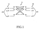
- FIG. 1 illustrates a simplified transmission model for a conventional MIMO system.
- the MIMO system is equipped with M transmit antennas 10 and M receive antennas 20.
- 's' denotes an (Mx1) signal vector transmitted from the M transmit antennas 10
- 'H' denotes a matrix representing the characteristics of a radio channel 15 that delivers the transmit signal vector s to a receiver.
- 'w' is Gaussian noise, which is an (Nx1) vector because it is induced to each receive antenna.
- DSTTD One of the MIMO techniques proposed by the 3GPP that is attractinging a great deal of interest is DSTTD.
- FIG. 2 is a schematic block diagram of a typical DSTTD system.
- a transmitter 31 comprises two STTD encoders (ENCs) 32 and 34, each connected to two of four transmit antennas 36, while a receiver 40 comprises STTD decoders (DECs) 44, 46, 48, and 50, each pair of which is connected to one of N receive antennas 42 (where N ⁇ 2).
- ENCs STTD encoders
- DECs STTD decoders
- the DSTTD system having the above-described configuration performs one DSTTD combining and signal detection for every two symbols.
- the process speed is twice as fast and the system complexity is reduced, compared to an STTD system using four transmit antennas.
- Antenna shuffling is a technique for improving DSTTD performance in a radio channel environment with high antenna correlation.
- symbols from the two STTD encoders 32 and 34 based on the four transmit antennas 36 are prioritized. That is, the antenna shuffling linearly changes channels.
- An antenna shuffling pattern is determined according to spatial channel correlation by the receiver.
- the receiver After estimating channel characteristics, the receiver extracts a spatial correlation matrix representing a correlation between the transmitter and the receiver from the channel estimation information and determines an optimum shuffling pattern that minimizes the correlation.
- the correlation matrix must be an identity matrix to maintain full channel independency, off-orthogonal terms are produced due to noise and interference in real implementation.
- the receiver determines a shuffling pattern that minimizes the off-orthogonal terms and notifies the encoders of the transmitter of the shuffling pattern.
- the conventional DSTTD system selects a shuffling pattern based only on information that minimizes spatial correlation between channels on which data streams are transmitted, with no regard to SNR (Signal to Noise Ratio) having effects on BER (Bit Error Rate) at the receiver.
- SNR Signal to Noise Ratio
- BER Bit Error Rate
- an aspect of the present invention is to substantially solve at least the above problems and/or disadvantages and to provide at least the advantages below.
- Another aspect of the present invention is to provide a method and apparatus for determining a shuffling pattern that minimizes error probability based on channel estimation information in a DSTTD system.
- a further aspect of the present invention is to provide a method and apparatus for determining a shuffling pattern that maximizes a minimum receive SNR directly from channel estimation information in a DSTTD system.
- the above is achieved by providing a method and apparatus for determining a shuffling pattern in a DSTTD system.
- channel characteristics are estimated from a plurality of transmit antennas to a plurality of receive antennas, and an optimum shuffling pattern that maximizes a receive SNR is selected according to the estimated channel characteristics.
- a channel estimator estimates channel characteristics from a plurality of transmit antennas to a plurality of receive antennas
- a shuffling pattern selector selects an optimum shuffling pattern that maximizes a receive SNR according to the estimated channel characteristics
- a plurality of decoders decodes signals received from the transmit antennas at the receive antennas and deshuffles the decoded signals in the optimum shuffling pattern
- a detector detects data symbols from the deshuffled signals.
- the present invention as described below pertains to a method of determining, based on channel estimation information, a shuffling pattern leading to a largest minimum receive SNR that has a direct effect on BER performance at a receiver in a DSTTD system supporting shuffling.
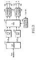
- FIG. 3 is a block diagram of a transmitter in a DSTTD system supporting shuffling according to an embodiment of the present invention.
- a demultiplexer (DEMUX) 110 separates one data stream including a plurality of modulated data symbols into two different data streams and feeds them to STTD encoders 120 and 122, respectively.
- the STTD encoders 120 and 122 each generate two data streams for the input of one data stream. Consequently, they together output four data streams.
- a shuffler 130 shuffles the signals received from the four antenna-based STTD encoders 120 and 122 according to a shuffling pattern provided from a shuffling controller 160.
- the antenna shuffling linearly changes channels from the transmitter to a receiver.
- the receiver determines a shuffling pattern, which will be described in more detail later.
- Spreaders 140, 142, 144, and 146 spread the shuffled four data streams received from the shuffler 130 with multiple spreading codes and assign the spread signals to transmit antennas 150, 152, 154, and 156, respectively.
- the transmission signals assigned to the first and second transmit antennas 150 and 152 are orthogonal to each other due to the STTD coding. Likewise, orthogonal transmission signals are assigned to the third and fourth transmit antennas 154 and 156. The signal transmitted from each antenna is interfered with by the signals from the other STTD encoder. Therefore, transmit diversity is effected on each data symbol.
- FIG. 4 is a block diagram of a receiver in the DSTTD system supporting shuffling according to the embodiment of the present invention.
- a despreader 220 despreads signals received through N receive antennas 210 to 212, respectively.
- Each pair of STTD decoders 232 to 238 performs direct space-time rake combining for each antenna.
- a signal received at an nth receive antenna for a DSTTD coded signal transmitted over the channel (matrix H) is determined by: where h ni is a channel coefficient for an ith symbol time, s j is a jth transmitted symbol, and w n ( ⁇ ) is Gaussian noise.
- a channel estimator 260 estimates channel characteristics from the transmit antennas to the receive antennas using the signals received through the receive antennas, determines an optimum shuffling pattern W, and provides it to the decoders 232 to 238 and the transmitter.
- the decoders 232 to 238 deshuffle the combined signals in the original order according to the shuffling pattern W.
- Each of the DSTTD combined signals are affected by interference signals generated from two transmit antennas connected to the other STTD encoder. Therefore, a detector 240 detects data symbols by applying an algorithm designed for canceling the interference, such as iterative MMSE (Minimum Mean Square Error), to the signals output from the decoders 232 to 238.
- a parallel to serial converter (P/S) converts the data symbols to a serial symbol sequence and feeds it to a demodulator (not shown).
- FIG. 5 illustrates an exemplary shuffling in a shuffling pattern (1, 3, 2, 4). As illustrated in FIG. 5, the shuffler 130 exchanges a second data stream with a third data stream
- a minimum receive SNR which represents the worst radio channel environment, is a dominant factor that directly determines the BER performance of the receiver. Therefore, a shuffling pattern selector 270 detects a shuffling pattern that maximizes the minimum receive SNR.
- the receiver in the DSTTD system uses a ZF (Zero Forcing) or MMSE detection algorithm and detects data from each data stream by the algorithm.
- the receive SNR of a kth data stream detected by the algorithm is determined by: where ⁇ is the total SNR of the transmitted signal, M is the number of the transmit antennas, H is a channel matrix, superscript H denotes Hermitian matrix, and subscript k,k denotes the index of the data stream.
- H is a matrix representing channel characteristics varying with the DSTTD system, that is, channel characteristics appearing after shuffling in the transmitter. For four transmit antennas and two receive antennas, H is expanded with respect to time from Eq. (2) to
- the minimum receive SNR is developed to where ⁇ max ( ⁇ ) and ⁇ min ( ⁇ ) are functions of computing the largest and least eigen values of the channel matrix, respectively.
- W min arg max w ⁇ min ( W H H H HW ) ⁇ where W is a matrix, which can be considered as a shuffling pattern. Due to the symmetrical structure of the system, all available shuffling patterns are shown below in Eq. (9).
- the shuffling pattern selector 270 selects a W min that satisfies Eq. (8) from among the above shuffling patterns and feeds back information about the selected shuffling pattern to the transmitter.
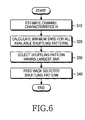
- FIG. 6 is a flowchart illustrating an operation for determining a shuffling pattern according to the embodiment of the present invention. This operation is performed by the receiver in the DSTTD system where DSTTD coded data streams are shuffled in a predetermined shuffling pattern prior to transmission.
- the receiver estimates channel characteristics from a plurality of transmit antennas to receive antennas in step 310 and calculates a minimum SNR for each of all available shuffling patterns, based on the estimated channel characteristics in step 320.
- the receiver selects a shuffling pattern having a largest minimum SNR as an optimum shuffling pattern.
- the receiver feeds back information about the selected shuffling pattern to the transmitter in step 340.
- H iid is an NxM i.i.d. (independent and identically distributed) complex Gaussian channel matrix with zero mean and unit variance
- R RX and R TX are an NxN reception correlation matrix and an MxM transmission correlation matrix, respectively.
- FIG. 7 illustrates BER performance that can be achieved by all available shuffling patterns for channel S1.
- Table 2 lists minimum SNRs and channel correlations for the shuffling patterns available to channel S1.
- the minimum SNR is a criterion by which an optimum shuffling pattern is selected in the present invention, whereas the channel correlation is the criterion in the conventional technology.
- Shuffling pattern Present invention (minimum SNR) Conventional (channel correlation) (1, 2, 3, 4) 0.6770 0.0010 (1, 3, 2, 4) 0.2411 0.0050 (1, 4, 2, 3) 0.3302 0.0022 (1, 2, 4, 3) 0.7609 0.0028 (1, 3, 4, 2) 0.7786 0.0004 (selected) (1, 4, 3, 2) 0.8021 (selected) 0.0030
- the shuffling pattern (1, 4, 3, 2) having the largest minimum SNR, 0.8021 is selected in the present invention, while the shuffling pattern (1, 3, 4, 2) having the least channel correlation, 0.0004 is selected in the conventional method. Because the selection is made based on the best receive SNR characteristic, the same shuffling pattern (1, 4, 3, 2) as resulted from the simulation is selected in the present invention.
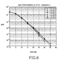
- FIG. 8 illustrates simulation results for all shuffling patterns available to channel S2.
- Table 3 lists minimum SNRs as data for selecting an optimum shuffling pattern in the present invention and channel correlations as data for selecting an optimum shuffling pattern in the conventional method, for the shuffling patterns available to channel S2.
- Shuffling pattern Present invention Conventional (channel correlation) (1, 2, 3, 4) 1.0226 0.0021 (1, 3, 2, 4) 1.1186 0.0044 (1, 4, 2, 3) 1.1152 0.0045 (1, 2, 4, 3) 1.1321 (selected) 0.0065 (1, 3, 4, 2) 1.1109 0.0018 (selected) (1, 4, 3, 2) 1.0154 0.0050
- S2 offers the best BER performance in the shuffling pattern of (1, 2, 4, 3) or (1, 3, 4, 2).
- the present invention selects the shuffling pattern (1, 3, 4, 2) having the largest minimum SNR, 1.1321, while the conventional method selects the shuffling pattern having the least channel correlation, 0.0018.
- FIG. 9 illustrates simulation results for all shuffling patterns available to channel S3.
- Table 4 lists minimum SNRs as data for selecting an optimum shuffling pattern in the present invention and channel correlations as data for selecting an optimum shuffling pattern in the conventional method, for the shuffling patterns available to channel S3.
- Shuffling pattern Present invention Conventional (channel correlation) (1, 2, 3, 4) 0.3381 0.0064 (1, 3, 2, 4) 0.7509 0.0042 (1, 4, 2, 3) 0.7940 0.0018 (selected) (1, 2, 4, 3) 0.3437 0.0044 (1, 3, 4, 2) 0.7426 0.0105 (1, 4, 3, 2) 0.7952 (selected) 0.0041
- the present invention selects the shuffling pattern (1, 4, 2, 3) having the largest minimum SNR, 0.7952.
- the simulation reveals that the conventional method does not present a uniform decision criterion for the shuffling patterns, W 1324 , W 1423 , W 1342 , and W 1432 having similar performance, while the present invention presents a uniform decision criterion for these shuffling patterns. Therefore, it is concluded that the present invention is objective in determining an optimum shuffling pattern, compared to the conventional method.
- an optimum shuffling pattern is efficiently determined in a DSTTD system supporting shuffling.
- a receiver estimates channels and calculates from the channel estimation information received SNRs that directly affect the BER performance of the receiver, without rebuilding a spatial channel correlation matrix. Therefore, reception performance is improved.
Abstract
A method and apparatus for determining a shuffling pattern in a DSTTD.
In the apparatus, a channel estimator estimates channel characteristics from a
plurality of transmit antennas to a plurality of receive antennas. A shuffling
pattern selector calculates a minimum receive SNR for each of all available
shuffling patterns, and selects a shuffling pattern having the largest minimum
receive SNR as the optimum shuffling pattern. This efficient shuffling pattern
selection directly improves BER performance at a receiver.
Description
- The present invention relates generally to a double space-time transmit diversity (DSTTD) system, and in particular, to a method and apparatus for selecting a shuffling pattern in a DSTTD system that shuffles data streams for transmission.
- As a result of the rapid growth of the wireless mobile communication market and the increasing demands for diverse multimedia services in a radio environment, methods of transmitting increasing amounts of data and that at higher rates are being explored. Therefore, efficient use of limited frequency resources has emerged as a pressing issue. As a result, a new transmission scheme using multiple antennas is needed. The standardization working group for 3rd generation mobile communication systems, 3GPP (3rd Generation Partnership Project), is actively discussing new data transmission schemes using the MIMO (Multiple Input and Multiple Output) technology of transmitting/receiving data through multiple transmit/receive antennas in a mobile communication environment.
- FIG. 1 illustrates a simplified transmission model for a conventional MIMO system. Referring to FIG. 1, the MIMO system is equipped with M transmit antennas 10 and M receive antennas 20. 's' denotes an (Mx1) signal vector transmitted from the M transmit antennas 10 and 'H' denotes a matrix representing the characteristics of a radio channel 15 that delivers the transmit signal vector s to a receiver. A received signal vector r received at the receiver through the N receive antennas is determined as follows:
- One of the MIMO techniques proposed by the 3GPP that is attractinging a great deal of interest is DSTTD. The use of two STTD encoders based on conventional STTD coding effects transmit diversity, which renders the DSTTD feasible for situations requiring diversity-based performance improvement.
- FIG. 2 is a schematic block diagram of a typical DSTTD system. Referring to FIG 2, a transmitter 31 comprises two STTD encoders (ENCs) 32 and 34, each connected to two of four transmit antennas 36, while a receiver 40 comprises STTD decoders (DECs) 44, 46, 48, and 50, each pair of which is connected to one of N receive antennas 42 (where N≥2).
- The DSTTD system having the above-described configuration performs one DSTTD combining and signal detection for every two symbols. Thus, the process speed is twice as fast and the system complexity is reduced, compared to an STTD system using four transmit antennas.
- Antenna shuffling is a technique for improving DSTTD performance in a radio channel environment with high antenna correlation. For antenna shuffling, symbols from the two STTD encoders 32 and 34 based on the four transmit antennas 36 are prioritized. That is, the antenna shuffling linearly changes channels. An antenna shuffling pattern is determined according to spatial channel correlation by the receiver.
- After estimating channel characteristics, the receiver extracts a spatial correlation matrix representing a correlation between the transmitter and the receiver from the channel estimation information and determines an optimum shuffling pattern that minimizes the correlation. Although the correlation matrix must be an identity matrix to maintain full channel independency, off-orthogonal terms are produced due to noise and interference in real implementation. Thus, the receiver determines a shuffling pattern that minimizes the off-orthogonal terms and notifies the encoders of the transmitter of the shuffling pattern.
- The conventional DSTTD system, however, selects a shuffling pattern based only on information that minimizes spatial correlation between channels on which data streams are transmitted, with no regard to SNR (Signal to Noise Ratio) having effects on BER (Bit Error Rate) at the receiver. Moreover, considering the correlation matrix is derived by two-dimensional computation, not one-dimensionally from the channel matrix, there are limitations in estimating a shuffling pattern that lead to optimum reception performance with use of the correlation matrix only.
- Therefore, an aspect of the present invention is to substantially solve at least the above problems and/or disadvantages and to provide at least the advantages below.
- It is the object of the present invention to provide a method and apparatus for determining a shuffling pattern for an optimum reception performance, and minimizing receiver complexity in a DSTTD system.
- This object is solved by the subject matter of the independent claims. Preferred embodiments are defined in the dependent claims.
- Another aspect of the present invention is to provide a method and apparatus for determining a shuffling pattern that minimizes error probability based on channel estimation information in a DSTTD system.
- A further aspect of the present invention is to provide a method and apparatus for determining a shuffling pattern that maximizes a minimum receive SNR directly from channel estimation information in a DSTTD system.
- The above is achieved by providing a method and apparatus for determining a shuffling pattern in a DSTTD system.
- According to one aspect of the present invention, in a method of determining a shuffling pattern in a DSTTD system in which DSTTD coded data streams are shuffled in the shuffling pattern prior to transmission, channel characteristics are estimated from a plurality of transmit antennas to a plurality of receive antennas, and an optimum shuffling pattern that maximizes a receive SNR is selected according to the estimated channel characteristics.
- According to another aspect of the present invention, in an apparatus for determining a shuffling pattern in a DSTTD system in which DSTTD coded data streams are shuffled in the shuffling pattern prior to transmission, a channel estimator estimates channel characteristics from a plurality of transmit antennas to a plurality of receive antennas, a shuffling pattern selector selects an optimum shuffling pattern that maximizes a receive SNR according to the estimated channel characteristics, a plurality of decoders decodes signals received from the transmit antennas at the receive antennas and deshuffles the decoded signals in the optimum shuffling pattern, and a detector detects data symbols from the deshuffled signals.
- The above features and advantages of the present invention will become more apparent from the following detailed description when taken in conjunction with the accompanying drawings in which:
- FIG 1 illustrates a simplified transmission model for a conventional MIMO system; FIG. 2 is a schematic block diagram of a conventional DSTTD system; FIG 3 is a block diagram of a transmitter in a DSTTD system supporting shuffling according to an embodiment of the present invention;
- FIG. 4 is a block diagram of a receiver in the DSTTD system supporting shuffling according to the embodiment of the present invention;
- FIG. 5 illustrates an example of shuffling in the DSTTD system supporting shuffling according to the embodiment of the present invention;
- FIG. 6 is a flowchart illustrating an operation for deciding a shuffling pattern according to the embodiment of the present invention; and
- FIGs. 7, 8, and 9 are graphs illustrating BER performance for all available shuffling patterns.
-
- A preferred embodiment of the present invention will be described herein below with reference to the accompanying drawings. In the following description, well-known functions or constructions are not described in detail since they would obscure the invention in unnecessary detail.
- The present invention as described below pertains to a method of determining, based on channel estimation information, a shuffling pattern leading to a largest minimum receive SNR that has a direct effect on BER performance at a receiver in a DSTTD system supporting shuffling.
- FIG. 3 is a block diagram of a transmitter in a DSTTD system supporting shuffling according to an embodiment of the present invention. Referring to FIG. 3, a demultiplexer (DEMUX) 110 separates one data stream including a plurality of modulated data symbols into two different data streams and feeds them to STTD encoders 120 and 122, respectively. The STTD encoders 120 and 122, each generate two data streams for the input of one data stream. Consequently, they together output four data streams.
- For antenna shuffling, a shuffler 130 shuffles the signals received from the four antenna-based STTD encoders 120 and 122 according to a shuffling pattern provided from a shuffling controller 160. The antenna shuffling linearly changes channels from the transmitter to a receiver. The receiver determines a shuffling pattern, which will be described in more detail later.
Spreaders 140, 142, 144, and 146 spread the shuffled four data streams received from the shuffler 130 with multiple spreading codes and assign the spread signals to transmit antennas 150, 152, 154, and 156, respectively. - The transmission signals assigned to the first and second transmit antennas 150 and 152 are orthogonal to each other due to the STTD coding. Likewise, orthogonal transmission signals are assigned to the third and fourth transmit antennas 154 and 156. The signal transmitted from each antenna is interfered with by the signals from the other STTD encoder. Therefore, transmit diversity is effected on each data symbol.
- FIG. 4 is a block diagram of a receiver in the DSTTD system supporting shuffling according to the embodiment of the present invention. Referring to FIG. 4, a despreader 220 despreads signals received through N receive antennas 210 to 212, respectively. Each pair of STTD decoders 232 to 238 performs direct space-time rake combining for each antenna.
- A signal received at an nth receive antenna for a DSTTD coded signal transmitted over the channel (matrix H) is determined by:where hni is a channel coefficient for an ith symbol time, sj is a jth transmitted symbol, and wn(·) is Gaussian noise.

- A channel estimator 260 estimates channel characteristics from the transmit antennas to the receive antennas using the signals received through the receive antennas, determines an optimum shuffling pattern W, and provides it to the decoders 232 to 238 and the transmitter. The decoders 232 to 238 deshuffle the combined signals in the original order according to the shuffling pattern W.
- Each of the DSTTD combined signals are affected by interference signals generated from two transmit antennas connected to the other STTD encoder. Therefore, a detector 240 detects data symbols by applying an algorithm designed for canceling the interference, such as iterative MMSE (Minimum Mean Square Error), to the signals output from the decoders 232 to 238. A parallel to serial converter (P/S) converts the data symbols to a serial symbol sequence and feeds it to a demodulator (not shown).
- If the channel coefficient of each antenna iswhere W is a 4x4 permutation matrix representing the shuffling pattern and superscript T denotes permutation matrix.

- FIG. 5 illustrates an exemplary shuffling in a shuffling pattern (1, 3, 2, 4). As illustrated in FIG. 5, the shuffler 130 exchanges a second data stream with a third data stream
- A minimum receive SNR, which represents the worst radio channel environment, is a dominant factor that directly determines the BER performance of the receiver. Therefore, a shuffling pattern selector 270 detects a shuffling pattern that maximizes the minimum receive SNR.
- The receiver in the DSTTD system uses a ZF (Zero Forcing) or MMSE detection algorithm and detects data from each data stream by the algorithm. The receive SNR of a kth data stream detected by the algorithm is determined by:where ρ is the total SNR of the transmitted signal, M is the number of the transmit antennas, H is a channel matrix, superscript H denotes Hermitian matrix, and subscript k,k denotes the index of the data stream.

- H is a matrix representing channel characteristics varying with the DSTTD system, that is, channel characteristics appearing after shuffling in the transmitter. For four transmit antennas and two receive antennas, H is expanded with respect to time from Eq. (2) to

- From Eq. (6), the minimum receive SNR is developed towhere λmax(·) and λmin(·) are functions of computing the largest and least eigen values of the channel matrix, respectively.

- As a result, a shuffling pattern Wmin is detected, which maximizes Eq. (7) for the channel matrix H, which varies depending on shuffling. This can be expressed as follows:

- The shuffling pattern selector 270 selects a Wmin that satisfies Eq. (8) from among the above shuffling patterns and feeds back information about the selected shuffling pattern to the transmitter.
- FIG. 6 is a flowchart illustrating an operation for determining a shuffling pattern according to the embodiment of the present invention. This operation is performed by the receiver in the DSTTD system where DSTTD coded data streams are shuffled in a predetermined shuffling pattern prior to transmission.
- Referring to FIG. 6, the receiver estimates channel characteristics from a plurality of transmit antennas to receive antennas in step 310 and calculates a minimum SNR for each of all available shuffling patterns, based on the estimated channel characteristics in step 320. In step 330, the receiver selects a shuffling pattern having a largest minimum SNR as an optimum shuffling pattern. The receiver feeds back information about the selected shuffling pattern to the transmitter in step 340.
- The performance of the receiver using the inventive shuffling pattern determining algorithm was simulated under an environment having various channel correlations. The simulation results will be presented below.
- The simulation was under the conditions of M transmit antennas and N receive antennas. In Eq. (10), Hiid is an NxM i.i.d. (independent and identically distributed) complex Gaussian channel matrix with zero mean and unit variance, and RRX and RTX are an NxN reception correlation matrix and an MxM transmission correlation matrix, respectively.
- Channel correlation models used for the simulation are listed in Table 1 below. Because there is usually sufficient scattering around the receiver and thus, channel independency is ensured between receive antennas, it can be said that no receive correlation exists. Therefore, RRX=1.
Model Parameter S1 One transmitter cluster. AOD=π/2. AOS=π/30; RRX=1 S2 Two equal transmit clusters. AOD=[π/6, π/2]. AOS=[π/30, π/20]; RRX=1 S3 RTX=toeplitz([1.075 0.5 0.25]); RRX=1 - For channel S1, there is no receive correlation and a channel with a transmit correlation is generated from one cluster. The AOD (Angle Of Departure) and AOS (Angle Of Spread) are π/2 and π/30, respectively. An optimum antenna shuffling pattern for S1 is (1, 4, 3, 2). FIG. 7 illustrates BER performance that can be achieved by all available shuffling patterns for channel S1.
- Table 2 lists minimum SNRs and channel correlations for the shuffling patterns available to channel S1. The minimum SNR is a criterion by which an optimum shuffling pattern is selected in the present invention, whereas the channel correlation is the criterion in the conventional technology.
Shuffling pattern Present invention (minimum SNR) Conventional (channel correlation) (1, 2, 3, 4) 0.6770 0.0010 (1, 3, 2, 4) 0.2411 0.0050 (1, 4, 2, 3) 0.3302 0.0022 (1, 2, 4, 3) 0.7609 0.0028 (1, 3, 4, 2) 0.7786 0.0004 (selected) (1, 4, 3, 2) 0.8021 (selected) 0.0030 - According to Table 2, the shuffling pattern (1, 4, 3, 2) having the largest minimum SNR, 0.8021 is selected in the present invention, while the shuffling pattern (1, 3, 4, 2) having the least channel correlation, 0.0004 is selected in the conventional method. Because the selection is made based on the best receive SNR characteristic, the same shuffling pattern (1, 4, 3, 2) as resulted from the simulation is selected in the present invention.
- For channel S2, channels with transmit correlation are generated from two clusters. Their AODs and AOSs are π/6 & π/2 and π/30 & π/20, respectively. FIG. 8 illustrates simulation results for all shuffling patterns available to channel S2. Table 3 lists minimum SNRs as data for selecting an optimum shuffling pattern in the present invention and channel correlations as data for selecting an optimum shuffling pattern in the conventional method, for the shuffling patterns available to channel S2.
Shuffling pattern Present invention (minimum SNR) Conventional (channel correlation) (1, 2, 3, 4) 1.0226 0.0021 (1, 3, 2, 4) 1.1186 0.0044 (1, 4, 2, 3) 1.1152 0.0045 (1, 2, 4, 3) 1.1321 (selected) 0.0065 (1, 3, 4, 2) 1.1109 0.0018 (selected) (1, 4, 3, 2) 1.0154 0.0050 - It is noted from FIG. 8 that S2 offers the best BER performance in the shuffling pattern of (1, 2, 4, 3) or (1, 3, 4, 2). Referring to Table 3, the present invention selects the shuffling pattern (1, 3, 4, 2) having the largest minimum SNR, 1.1321, while the conventional method selects the shuffling pattern having the least channel correlation, 0.0018.
- For channel S3, the transmit correlation is forcibly applied and the transmit correlation matrix RTX=toeplitz(1 0.75 0.5 0.25). FIG. 9 illustrates simulation results for all shuffling patterns available to channel S3. Table 4 lists minimum SNRs as data for selecting an optimum shuffling pattern in the present invention and channel correlations as data for selecting an optimum shuffling pattern in the conventional method, for the shuffling patterns available to channel S3.
Shuffling pattern Present invention (minimum SNR) Conventional (channel correlation) (1, 2, 3, 4) 0.3381 0.0064 (1, 3, 2, 4) 0.7509 0.0042 (1, 4, 2, 3) 0.7940 0.0018 (selected) (1, 2, 4, 3) 0.3437 0.0044 (1, 3, 4, 2) 0.7426 0.0105 (1, 4, 3, 2) 0.7952 (selected) 0.0041 - Referring to Table 4, the present invention selects the shuffling pattern (1, 4, 2, 3) having the largest minimum SNR, 0.7952.
- The simulation reveals that the conventional method does not present a uniform decision criterion for the shuffling patterns, W1324, W1423, W1342, and W1432 having similar performance, while the present invention presents a uniform decision criterion for these shuffling patterns. Therefore, it is concluded that the present invention is objective in determining an optimum shuffling pattern, compared to the conventional method.
- According, in the present invention, an optimum shuffling pattern is efficiently determined in a DSTTD system supporting shuffling. In the shuffling pattern determining algorithm of the present invention, a receiver estimates channels and calculates from the channel estimation information received SNRs that directly affect the BER performance of the receiver, without rebuilding a spatial channel correlation matrix. Therefore, reception performance is improved.
- While the present invention has been shown and described with reference to a certain preferred embodiment thereof, it will be understood by those skilled in the art that various changes in form and details may be made therein without departing from the scope of the present invention as defined by the appended claims.
Claims (7)
- A method of determining a shuffling pattern in a double space-time transmit diversity-system in which double space-time transmit diversity coded data streams are shuffled in the shuffling pattern prior to transmission, comprising the steps of:estimating channel characteristics from a plurality of transmit antennas to a plurality of receive antennas; andselecting an optimum shuffling pattern that maximizes a receive signal to noise ratio based on the estimated channel characteristics.
- The method of claim 1, wherein the step of selecting the optimum shuffling pattern comprises the steps of:calculating a minimum receive signal to noise ratio for each of all available shuffling patterns; andselecting a shuffling pattern having a largest minimum receive signal to noise ratio as the optimum shuffling pattern.
- The method of claim 1 or 2, wherein in the step of selecting the optimum shuffling pattern, the optimum shuffling pattern maximizes
- An apparatus for determining a shuffling pattern in a double space-time transmit diversity-system in which double space-time transmit diversity coded data streams are shuffled in the shuffling pattern prior to transmission, comprising:a channel estimator for estimating channel characteristics from a plurality of transmit antennas to a plurality of receive antennas;a shuffling pattern selector for selecting an optimum shuffling pattern that maximizes a receive signal to noise ratio based on the estimated channel characteristics;a plurality of decoders for decoding signals received from the plurality of transmit antennas at the plurality of receive antennas, and deshuffling the decoded signals in the optimum shuffling pattern; anda detector for detecting data symbols from the deshuffled signals.
- The apparatus of claim 4, wherein the shuffling pattern selector calculates a minimum receive signal to noise ratio for each of all available shuffling patterns, and selects a shuffling pattern having a largest minimum receive signal to noise ratio as the optimum shuffling pattern.
- The apparatus of claim 4 or 5, wherein the shuffling pattern selector selects the optimum shuffling pattern maximizes
- The apparatus of one of claims 4 to 6, wherein the shuffling pattern selector feeds back information about the optimum shuffling pattern to a transmitter.
Applications Claiming Priority (2)
| Application Number | Priority Date | Filing Date | Title |
|---|---|---|---|
| KR2003054676 | 2003-08-07 | ||
| KR1020030054676A KR20050015731A (en) | 2003-08-07 | 2003-08-07 | Method and apparatus for deciding shuffling pattern in double space-time transmit diversity system using minimum signal to noise ratio |
Publications (1)
| Publication Number | Publication Date |
|---|---|
| EP1505758A1 true EP1505758A1 (en) | 2005-02-09 |
Family
ID=33550329
Family Applications (1)
| Application Number | Title | Priority Date | Filing Date |
|---|---|---|---|
| EP04017012A Withdrawn EP1505758A1 (en) | 2003-08-07 | 2004-07-19 | Method and apparatus for determining a shuffling pattern based on a minimum signal to noise ratio in a double space-time transmit diversity system |
Country Status (5)
| Country | Link |
|---|---|
| US (1) | US20050031062A1 (en) |
| EP (1) | EP1505758A1 (en) |
| JP (1) | JP2005057779A (en) |
| KR (1) | KR20050015731A (en) |
| CN (1) | CN1581725A (en) |
Cited By (4)
| Publication number | Priority date | Publication date | Assignee | Title |
|---|---|---|---|---|
| EP2007026A1 (en) | 2007-06-19 | 2008-12-24 | Lucent Technologies Inc. | Method for transmitting symbols encoded in a hybrid MIMO transceiver scheme, transmitter,receiver, and MIMO system |
| WO2010040369A1 (en) * | 2008-10-09 | 2010-04-15 | Telefonaktiebolaget Lm Ericsson (Publ) | Antenna arrangement for multi-stream communication in a mimo channel |
| WO2011063705A1 (en) * | 2009-11-24 | 2011-06-03 | 华为技术有限公司 | Receiving method and device in dual space time transmit diversity mode |
| EP2044717A4 (en) * | 2006-07-13 | 2017-06-28 | LG Electronics Inc. | Method and apparatus for transmitting data with time diversity and/or time-frequency diversity, and pattern-generating method to be used in the same |
Families Citing this family (29)
| Publication number | Priority date | Publication date | Assignee | Title |
|---|---|---|---|---|
| US7680212B2 (en) * | 2004-08-17 | 2010-03-16 | The Board Of Trustees Of The Leland Stanford Junior University | Linear precoding for multi-input systems based on channel estimate and channel statistics |
| US8995547B2 (en) | 2005-03-11 | 2015-03-31 | Qualcomm Incorporated | Systems and methods for reducing uplink resources to provide channel performance feedback for adjustment of downlink MIMO channel data rates |
| US8724740B2 (en) | 2005-03-11 | 2014-05-13 | Qualcomm Incorporated | Systems and methods for reducing uplink resources to provide channel performance feedback for adjustment of downlink MIMO channel data rates |
| CN1838556A (en) * | 2005-03-24 | 2006-09-27 | 松下电器产业株式会社 | Downlink multi-user space-time packet pre-coding method |
| BRPI0520150B1 (en) * | 2005-03-29 | 2017-10-31 | Micro Motion, Inc. | CORIOLIS FLOW METER AND METHOD FOR DETERMINING DRAINING CHARACTERISTICS |
| JP2006287756A (en) * | 2005-04-01 | 2006-10-19 | Ntt Docomo Inc | Transmitting apparatus, transmitting method, receiving apparatus, and receiving method |
| US8073068B2 (en) | 2005-08-22 | 2011-12-06 | Qualcomm Incorporated | Selective virtual antenna transmission |
| US20070041457A1 (en) | 2005-08-22 | 2007-02-22 | Tamer Kadous | Method and apparatus for providing antenna diversity in a wireless communication system |
| WO2007056892A1 (en) * | 2005-11-17 | 2007-05-24 | Huawei Technologies Co., Ltd. | Method and transmitter for improving the performance of transmit diversity in wireless system |
| TWI562572B (en) | 2006-01-11 | 2016-12-11 | Interdigital Tech Corp | Method and apparatus for implementing space time processing with unequal modulation and coding schemes |
| JP4356702B2 (en) * | 2006-03-03 | 2009-11-04 | ソニー株式会社 | Wireless communication apparatus and wireless communication method |
| CN101056162B (en) * | 2006-05-15 | 2011-09-21 | 华为技术有限公司 | Signal receiving and transmission method and device for MIMO system |
| WO2007137490A1 (en) * | 2006-05-15 | 2007-12-06 | Huawei Technologies Co., Ltd. | Signal transmitting and receiving method of mimo system and apparatus thereof |
| EP2547003B1 (en) | 2006-09-06 | 2014-10-15 | Qualcomm Incorporated | Codeword permutation and reduced feedback for grouped antennas |
| KR101383523B1 (en) * | 2007-08-14 | 2014-04-18 | 삼성전자주식회사 | Method and apparatus for detecting received signal in a communication system |
| EP2317666B1 (en) * | 2008-08-20 | 2014-05-14 | LG Innotek Co., Ltd. | Mimo communication system and control method thereof |
| JP5043080B2 (en) * | 2009-08-20 | 2012-10-10 | 株式会社エヌ・ティ・ティ・ドコモ | Communications system |
| CN102073479B (en) * | 2010-11-25 | 2013-03-27 | 中国人民解放军国防科学技术大学 | Data size-based shuffle switch matrix compression method |
| CN101986262B (en) * | 2010-11-25 | 2013-01-16 | 中国人民解放军国防科学技术大学 | Shuffle switch matrix compression method based on mode shift |
| KR20140115785A (en) * | 2013-03-22 | 2014-10-01 | 한국전자통신연구원 | Wireless link apparatus |
| CN103259547A (en) * | 2013-03-27 | 2013-08-21 | 安徽海聚信息科技有限责任公司 | Receiving device based on Zigbee technology |
| US9525444B2 (en) * | 2013-07-19 | 2016-12-20 | Analog Devices Global | Adaptive element shuffler |
| JP6240462B2 (en) * | 2013-10-15 | 2017-11-29 | 日本放送協会 | Transmission system |
| JP6259632B2 (en) * | 2013-10-15 | 2018-01-10 | 日本放送協会 | Digital broadcasting system, receiving device and chip |
| KR102150373B1 (en) * | 2014-03-05 | 2020-09-01 | 삼성전자주식회사 | A method and apparatus for feedback a channel with spatial correlation |
| KR102512844B1 (en) | 2016-06-29 | 2023-03-22 | 삼성전자주식회사 | Apparatus and method for permutation of block code in wireless communication system |
| CN110417695B (en) * | 2019-08-07 | 2020-07-03 | 厦门大学 | Reference diversity design algorithm of multistage code shift differential chaotic shift keying system |
| CN112631595B (en) * | 2019-10-09 | 2024-03-01 | 安徽寒武纪信息科技有限公司 | Shuffling method, shuffling device, computer equipment and readable storage medium |
| KR102467175B1 (en) * | 2019-12-27 | 2022-11-16 | 중앙대학교 산학협력단 | Method and system for transmitting/receiving data using multiple space time line codes/decodes |
Citations (3)
| Publication number | Priority date | Publication date | Assignee | Title |
|---|---|---|---|---|
| US20020196842A1 (en) * | 2001-03-30 | 2002-12-26 | Texas Instruments Incorporated | Closed loop multiple transmit, multiple receive antenna wireless communication system |
| US20030063654A1 (en) * | 2001-05-01 | 2003-04-03 | Onggosanusi Eko N. | Space-time transmit diversity |
| EP1437852A2 (en) * | 2003-01-09 | 2004-07-14 | Samsung Electronics Co., Ltd. | Data transmission/reception apparatus and method for archieving both multiplexing gain and diversity gain in a mobile communication system using space-time trellis code |
Family Cites Families (3)
| Publication number | Priority date | Publication date | Assignee | Title |
|---|---|---|---|---|
| EP1195937A1 (en) * | 2000-10-03 | 2002-04-10 | Telefonaktiebolaget Lm Ericsson | Space-time coding with orthogonal transformations |
| US7298717B2 (en) * | 2002-02-15 | 2007-11-20 | Texas Instruments Incorporated | Method and apparatus for providing transmit diversity with adaptive basis |
| US7295624B2 (en) * | 2002-03-06 | 2007-11-13 | Texas Instruments Incorporated | Wireless system with hybrid automatic retransmission request in interference-limited communications |
-
2003
- 2003-08-07 KR KR1020030054676A patent/KR20050015731A/en not_active Application Discontinuation
-
2004
- 2004-04-22 US US10/830,360 patent/US20050031062A1/en not_active Abandoned
- 2004-05-31 CN CNA2004100478522A patent/CN1581725A/en active Pending
- 2004-07-19 EP EP04017012A patent/EP1505758A1/en not_active Withdrawn
- 2004-08-04 JP JP2004228495A patent/JP2005057779A/en active Pending
Patent Citations (3)
| Publication number | Priority date | Publication date | Assignee | Title |
|---|---|---|---|---|
| US20020196842A1 (en) * | 2001-03-30 | 2002-12-26 | Texas Instruments Incorporated | Closed loop multiple transmit, multiple receive antenna wireless communication system |
| US20030063654A1 (en) * | 2001-05-01 | 2003-04-03 | Onggosanusi Eko N. | Space-time transmit diversity |
| EP1437852A2 (en) * | 2003-01-09 | 2004-07-14 | Samsung Electronics Co., Ltd. | Data transmission/reception apparatus and method for archieving both multiplexing gain and diversity gain in a mobile communication system using space-time trellis code |
Cited By (6)
| Publication number | Priority date | Publication date | Assignee | Title |
|---|---|---|---|---|
| EP2044717A4 (en) * | 2006-07-13 | 2017-06-28 | LG Electronics Inc. | Method and apparatus for transmitting data with time diversity and/or time-frequency diversity, and pattern-generating method to be used in the same |
| EP2007026A1 (en) | 2007-06-19 | 2008-12-24 | Lucent Technologies Inc. | Method for transmitting symbols encoded in a hybrid MIMO transceiver scheme, transmitter,receiver, and MIMO system |
| WO2010040369A1 (en) * | 2008-10-09 | 2010-04-15 | Telefonaktiebolaget Lm Ericsson (Publ) | Antenna arrangement for multi-stream communication in a mimo channel |
| WO2011063705A1 (en) * | 2009-11-24 | 2011-06-03 | 华为技术有限公司 | Receiving method and device in dual space time transmit diversity mode |
| CN103297114A (en) * | 2009-11-24 | 2013-09-11 | 华为技术有限公司 | Receiving method and receiving equipment of double space time transmit diversity mode |
| CN103297114B (en) * | 2009-11-24 | 2016-04-06 | 华为技术有限公司 | The method of reseptance of two space-time emission diversity pattern and equipment |
Also Published As
| Publication number | Publication date |
|---|---|
| JP2005057779A (en) | 2005-03-03 |
| KR20050015731A (en) | 2005-02-21 |
| US20050031062A1 (en) | 2005-02-10 |
| CN1581725A (en) | 2005-02-16 |
Similar Documents
| Publication | Publication Date | Title |
|---|---|---|
| EP1505758A1 (en) | Method and apparatus for determining a shuffling pattern based on a minimum signal to noise ratio in a double space-time transmit diversity system | |
| KR100575993B1 (en) | Method and apparatus for scheduling multi-user in wireless communication system using multiple transmit/receive antenna | |
| RU2291570C2 (en) | Spatial-temporal distancing during transfer for multiple antennas in radio communications | |
| KR100955795B1 (en) | Wireless communication using multi-transmit multi-receive antenna arrays | |
| JP4194038B2 (en) | Adaptive signal processing method in MIMO system | |
| RU2404511C2 (en) | Ofdm mimo system with controlled low-complexity directional diagram | |
| KR100938302B1 (en) | Method and apparatus for allocating resources in a multiple-input multiple output mimo communication system | |
| EP1575188A2 (en) | Apparatus and method for receiving signal in a multiple-input multiple-output communication system | |
| EP2208293B1 (en) | Wireless receiver with receive diversity | |
| EP1420529A2 (en) | Receiving apparatus, transmitting apparatus, and reception method in mimo system | |
| EP1587223A1 (en) | Detection process in a V-BLAST system | |
| EP1759470A1 (en) | Apparatus and method for beamforming in a multi-antenna system | |
| KR20040085680A (en) | Method for adaptive transmission and receiving in a wireless communication system with multiple antennas | |
| EP2356754B1 (en) | Mmse demodulation in a multi-user mimo system | |
| KR100943610B1 (en) | Apparatus and method for feedbacking antenna shuffling information in a multiple-input multiple-output system using a multiple space time block coding technique | |
| KR101106684B1 (en) | Apparatus and method for receiver in multiple antenna system | |
| JP2009100116A (en) | Wireless access system, base station apparatus and mobile station apparatus | |
| KR101274871B1 (en) | Method and apparatus for transceiving data in a multi antenna system of closed loop scheme | |
| JP2006005791A (en) | Estimation of communication path and data detection method | |
| KR100937917B1 (en) | Signal separation techniques to provide robust spread spectrum signal decoding | |
| KR20070005776A (en) | Mimo-based data transmission method | |
| EP1843486B1 (en) | Method of decoding a spatially multiplexed signal and its corresponding receiver | |
| RU2407147C2 (en) | Method of estimating distortion correlations in wireless communication receiver and device for realising said method | |
| EP1569356A1 (en) | Subtractive interference cancellation of pilot and control symbols before the data detection | |
| JP5339865B2 (en) | Wireless receiving method and wireless receiving device |
Legal Events
| Date | Code | Title | Description |
|---|---|---|---|
| PUAI | Public reference made under article 153(3) epc to a published international application that has entered the european phase |
Free format text: ORIGINAL CODE: 0009012 |
|
| 17P | Request for examination filed |
Effective date: 20040719 |
|
| AK | Designated contracting states |
Kind code of ref document: A1 Designated state(s): AT BE BG CH CY CZ DE DK EE ES FI FR GB GR HU IE IT LI LU MC NL PL PT RO SE SI SK TR |
|
| AX | Request for extension of the european patent |
Extension state: AL HR LT LV MK |
|
| AKX | Designation fees paid |
Designated state(s): DE FI FR GB IT SE |
|
| STAA | Information on the status of an ep patent application or granted ep patent |
Free format text: STATUS: THE APPLICATION HAS BEEN WITHDRAWN |
|
| 18W | Application withdrawn |
Effective date: 20070404 |