EP1510090B1 - Method for controlling parties in real-time data group communication using acknowledgement packets - Google Patents
Method for controlling parties in real-time data group communication using acknowledgement packets Download PDFInfo
- Publication number
- EP1510090B1 EP1510090B1 EP03727548A EP03727548A EP1510090B1 EP 1510090 B1 EP1510090 B1 EP 1510090B1 EP 03727548 A EP03727548 A EP 03727548A EP 03727548 A EP03727548 A EP 03727548A EP 1510090 B1 EP1510090 B1 EP 1510090B1
- Authority
- EP
- European Patent Office
- Prior art keywords
- real
- item
- user terminal
- time data
- sending
- Prior art date
- Legal status (The legal status is an assumption and is not a legal conclusion. Google has not performed a legal analysis and makes no representation as to the accuracy of the status listed.)
- Expired - Lifetime
Links
- 238000004891 communication Methods 0.000 title claims abstract description 144
- 238000000034 method Methods 0.000 title claims description 51
- 230000011664 signaling Effects 0.000 claims description 38
- 230000007246 mechanism Effects 0.000 claims description 19
- 230000006870 function Effects 0.000 claims description 13
- 238000012545 processing Methods 0.000 claims description 12
- 230000008569 process Effects 0.000 claims description 11
- 230000004044 response Effects 0.000 claims description 7
- 230000005540 biological transmission Effects 0.000 description 8
- 238000001914 filtration Methods 0.000 description 6
- 238000007726 management method Methods 0.000 description 6
- 230000004913 activation Effects 0.000 description 5
- 238000010586 diagram Methods 0.000 description 5
- 238000005516 engineering process Methods 0.000 description 5
- 238000010295 mobile communication Methods 0.000 description 4
- 238000013459 approach Methods 0.000 description 3
- 230000000694 effects Effects 0.000 description 3
- 230000000977 initiatory effect Effects 0.000 description 3
- 230000003139 buffering effect Effects 0.000 description 2
- 230000001413 cellular effect Effects 0.000 description 2
- 230000008859 change Effects 0.000 description 2
- 238000006243 chemical reaction Methods 0.000 description 2
- 230000006835 compression Effects 0.000 description 2
- 238000007906 compression Methods 0.000 description 2
- 238000013507 mapping Methods 0.000 description 2
- 230000001343 mnemonic effect Effects 0.000 description 2
- 238000000926 separation method Methods 0.000 description 2
- LZHQPJSJEITGHB-UHFFFAOYSA-N 2-[1-(hydroxymethyl)-2,6-dioxopiperidin-3-yl]isoindole-1,3-dione Chemical compound O=C1N(CO)C(=O)CCC1N1C(=O)C2=CC=CC=C2C1=O LZHQPJSJEITGHB-UHFFFAOYSA-N 0.000 description 1
- 240000003895 Aplectrum hyemale Species 0.000 description 1
- 235000004425 Aplectrum hyemale Nutrition 0.000 description 1
- 241000196324 Embryophyta Species 0.000 description 1
- 230000009471 action Effects 0.000 description 1
- 230000008901 benefit Effects 0.000 description 1
- 230000001934 delay Effects 0.000 description 1
- 238000012217 deletion Methods 0.000 description 1
- 230000037430 deletion Effects 0.000 description 1
- 230000001419 dependent effect Effects 0.000 description 1
- 238000013461 design Methods 0.000 description 1
- 238000001514 detection method Methods 0.000 description 1
- 238000011161 development Methods 0.000 description 1
- 230000009977 dual effect Effects 0.000 description 1
- 230000008030 elimination Effects 0.000 description 1
- 238000003379 elimination reaction Methods 0.000 description 1
- 230000006872 improvement Effects 0.000 description 1
- 230000004048 modification Effects 0.000 description 1
- 238000003825 pressing Methods 0.000 description 1
- 238000004088 simulation Methods 0.000 description 1
- 238000012546 transfer Methods 0.000 description 1
Images


Classifications
-
- H—ELECTRICITY
- H04—ELECTRIC COMMUNICATION TECHNIQUE
- H04L—TRANSMISSION OF DIGITAL INFORMATION, e.g. TELEGRAPHIC COMMUNICATION
- H04L65/00—Network arrangements, protocols or services for supporting real-time applications in data packet communication
- H04L65/1066—Session management
- H04L65/1101—Session protocols
- H04L65/1104—Session initiation protocol [SIP]
-
- H—ELECTRICITY
- H04—ELECTRIC COMMUNICATION TECHNIQUE
- H04L—TRANSMISSION OF DIGITAL INFORMATION, e.g. TELEGRAPHIC COMMUNICATION
- H04L12/00—Data switching networks
- H04L12/02—Details
- H04L12/16—Arrangements for providing special services to substations
- H04L12/18—Arrangements for providing special services to substations for broadcast or conference, e.g. multicast
- H04L12/1863—Arrangements for providing special services to substations for broadcast or conference, e.g. multicast comprising mechanisms for improved reliability, e.g. status reports
- H04L12/1868—Measures taken after transmission, e.g. acknowledgments
-
- H—ELECTRICITY
- H04—ELECTRIC COMMUNICATION TECHNIQUE
- H04L—TRANSMISSION OF DIGITAL INFORMATION, e.g. TELEGRAPHIC COMMUNICATION
- H04L65/00—Network arrangements, protocols or services for supporting real-time applications in data packet communication
- H04L65/1066—Session management
- H04L65/1101—Session protocols
Definitions
- the invention relates to communications systems, and especially to real-time data (two-party or multi-party) communication in communications systems.
- the most common call type is a call established between two parties for one-to-one communication.
- the standard way to set up a two-party call requires explicit control plane signalling that allows the call parties to establish a channel where the audio data can be transferred and to negotiate the communication capabilities; for example, the audio codec and the relative compression rate can be determined in this phase. Afterwards the actual voice communication can start and the audio data can be transmitted by the call parties.
- VoIP Voice over Internet Protocol
- SIP Session Initiation Protocol
- RFC 2543 The Session Initiation Protocol
- a mobile communications system refers generally to any telecommunications system which enables communication when users are moving within the service area of the system.
- a typical mobile communications system is a Public Land Mobile Network (PLMN).
- PLMN Public Land Mobile Network
- the mobile communications network is an access network providing a user with wireless access to external networks, hosts, or services offered by specific service providers.
- Byung-Won On et al. “A Reliable Multicast Protocol in Networks With Mobile Hosts", IEEE - ISBN 0-7695-0819-7 , discloses a method for managing and buffering multicast messages in network elements based on the message acknowledgements received from the targeted mobile hosts. The method seeks to avoid an overload in network elements. Similarly to Byung-Won On et al. referenced above, Byung-Won On et al.
- US 5809018 discloses a radio system providing a mobile subscriber with the possibility to select a group call in which the subscriber will participate with all ongoing group calls in current location of the subscriber while the subscriber station is already participating in another group call. This is achieved by sending information on other ongoing group calls to a subscriber station while the subscriber station is already participating in a first group call. This information may be displayed to the subscriber who can switch to a new group call if decided.
- US 6181685 discloses a solution for providing reverse power control for group call communications in CDMA systems. The solution is based on utilizing a power adjustment channel for the group call. The identification of the at least one power adjustment channel is sent to at least some of the subscriber units in the group. HONG Y. S.
- DAWS Digital advanced wireless services
- EUROCOMM 2000 presents future development and standardization of a new mobile broadband technology, DAWS.
- the basic idea is to develop a set of standards enabling support of the fast growing demand for professional mobile applications that require high bit rates.
- the requirements for DAWS are discussed regarding services and applications to be provided therein.
- WO 02 01780 A2 presents a method for receiving a radio communication system, where the downlink processing burden is shared between a group of local stations.
- US-A-5 375 068 discloses a video teleconferencing method and apparatus for computer workstations connected by a digital data network includes a transmission source portion for a local workstation to send audio and video teleconference data across the network to one or more remote workstations, and, a receiver for the local workstation to receive audio and video teleconference data back from the remote workstations.
- a slave process on the remote workstation issues a frame acknowledge message for each frame of video data successfully received from the local workstation at the remote workstation.
- PMR Professional mobile radio or private mobile radio
- PMR Professional mobile radio or private mobile radio
- PMR services are offered via dedicated PMR networks built with dedicated PMR technologies. This market is divided between several technologies - analog, digital, conventional and trunked - none of which has a dominating role.
- TETRA Transrestrial Trunked Radio
- ETSI European Telecommunications Standards Institute
- group communication refers to any logical group of three or more users intended to participate in the same group communication, e.g. a call.
- Group communication with a push-to-talk feature is one of the essential features of any PMR network.
- a group call is based on the use of a pressel (PTT, push-to-talk switch) in a telephone as a switch: by pressing a PTT the user indicates his desire to speak, and the user equipment sends a service request to the network.
- PTT push-to-talk switch
- the network either rejects the request or allocates the requested resources on the basis of predetermined criteria, such as the availability of resources, priority of the requesting user, etc.
- a connection is established also to all other active users in the specific subscriber group.
- the requesting user can talk and the other users can listen on the channel.
- the user equipment signals a release message to the network, and the resources are released.
- the resources are reserved only for the actual speech transaction or speech item, instead of reserving the resources for a "call".
- One interesting advantage of the push-to-talk communication, or more generally speech-item-by-speech-item communication is a short call setup time, which also makes such speech communication attractive to several other types of users.
- U.S. Patent 6,141,347 discloses a wireless communications system which uses multicast addressing and decentralized processing in group calls.
- a problem with such item-by-item communication is that a strict discipline or protocol is required from the parties in the speech communication, or other type of real-time data communication. Further, especially in group communication, it is difficult to know which the parties of the communication are at each specific moment, and therefore the communication must include spoken questions and acknowledgements.
- An object of the invention is to provide a new way to control parties in an item-by-item real-time data communication.
- each receiving user terminal acknowledges the reception of a real-time data item by sending a real-time data item acknowledgement report after the end of the item.
- the acknowledgement report may be sent after a successful reception of real-time data item, unsuccessful reception of real-time data item or in both cases, depending on the implementation and/or the user's selection.
- the report may also contain information relating to the quality of the connection.
- the receiving terminal sends an acknowledgement report only in response to a specific request sent by the sending user terminal from which the real-time data item originated, and no report is sent otherwise. This embodiment allows unnecessary reports to be avoided if the sending party is not interested in them.
- the report is sent as a default.
- each acknowledgement report is forwarded over a communication system to the sending user terminal from which the real-time data item originated.
- no extra functionality is needed in the communication system infrastructure for the present invention.
- a communication system infrastructure collects acknowledgement reports from a plurality of receiving user terminals and sends a combined acknowledgement report to the sending user terminal from which the real-time data item originated. This embodiment requires extra functionality in the communication system infrastructure for the invention but, on the other hand, requires less transmission capacity.
- the sending user terminal When the sending user terminal receives the acknowledgement report(s) after the real-time data item has ended, it may display information which indicates to a sending user which terminal(s) or user(s) were receiving the previous real-time data item.
- the present invention alleviates the problem of knowing who actually received the transmitted real-time data.
- the sending user automatically knows who received the previous real-time data item. Consequently, the users are no longer required to give this information themselves, as is the case in the prior art systems.
- embedded (i.e. implicit) signalling in a real-time data traffic is employed for transferring a request for an acknowledgement report and/or the acknowledgement report(s).
- Embedded signalling makes it unnecessary to reserve another bearer for the control signalling, which saves network resources and allows a short connection setup time to be achieved.
- the acknowledgement report(s) is transferred using outband signalling, such as SIP signalling.
- packet mode speech communication is employed, such as Internet Protocol (IP) packets or VolP speech communications.
- IP Internet Protocol
- VolP speech communications such as Internet Protocol (IP) packets or VolP speech communications.
- the embedded signalling comprises sending a leader packet from a sending user terminal to at least one receiving user terminal.
- the leader packet starts a real-time data item.
- the leader packet is employed for requesting the receiving user terminal(s) to send an acknowledgement report when the respective real-time data item has ended.
- audio packets that may contain no signalling but may contain only part of the real-time data item are sent.
- a trailer packet is the last part of the real-time data item and may be used by the receiving user terminal(s) to detect the end of the real-time data item.
- the present invention is applicable to any communications system allowing real-time data communication between end users on the item by item basis.
- the real-time data may include real-time audio (e.g. speech), real-time video, or any other real-time data, or combination thereof, i.e. real-time multimedia.
- the present invention is especially applicable to any communications system allowing packet-mode real-time data communication, such as IP packet communication between end users.
- the real-time data communication may be carried out between end user terminals over the Internet, for example.
- the present invention offers a significant improvement for packet-mode speech communications.
- the IP voice communication method employed is the Voice over IP (VoIP), but the invention is not limited to this particular method.
- VoIP Voice over IP
- One application field of the invention is in mobile packet radio communications systems.
- embodiments of the invention will be described by means of a GPRS type packet radio service and the UMTS or GSM system, without limiting the invention to these communication systems.
- FIG. 1 illustrates an example wherein a packet mode speech communication service is embodied within a server based core network (CN) with different control and user-plane's logical entities serving the subscribers connected thereto.
- CN server based core network
- This concept and architecture is illustrated in more detail in the copending U.S. patent applications 09/835,867 and 09/903,871 .
- the subscribers' transmissions are proxied and forwarded by these CN entities, which do not allow direct end-to-end transmissions between the subscribers.
- call processing servers (CPS) and user-plane functions (Bridge) may also be within the access communication network, providing a top protocol layer for the access network.
- the communication system 12 may be a mobile radio access network (RAN) which provides the IP packet data service which may be based on a GPRS architecture utilizing a second generation (2G) or third generation (3G) radio access technology.
- RAN mobile radio access network
- 2G second generation
- 3G third generation
- any communication system supporting a packet mode voice communication can be employed instead of the mobile network described above.
- the type of the underlying network layer i.e. "the access network” is not essential to the basic invention. Some embodiments of the invention can be embodied in the end-user terminals without any supporting functionality on the network side.
- a packet mode voice communication layer 13 (or a core network CN) is provided on top of the mobile network in order to provide communication services to the user terminals through the communications system, e.g. mobile network.
- This layer can be called a Push-to-talk over Cellular (PoC) layer.
- the packet mode voice communication layer 13 may comprise a pair of basic logical entities, a bridge 10 and a call processing server (CPS) 11.
- the bridge 10 and the CPS server 11 run packet mode voice communication applications, which communicate with the packet mode voice communication application(s) in the user terminals over the IP connections provided by the IP communication system. This communication includes both signalling packets and voice (group or one-to-one) communication packets.
- the CPS 11 may be responsible for control-plane management of the packet mode voice communications. Its important role may require various functionalities, managing the user activity and creation and deletion of logical user-plane connections with an appropriate control protocol, such as Session Initiation Protocol SIP, and management of the user profiles (call rights, group active membership, scanning settings, etc.); SIP Proxy/Location Server - providing user location and routing functionalities of SIP signalling; SIP Registrar - for user registration/authentication; and Media Gateway Controller - controlling the network entities (PoC bridges) involved in the IP layer data distribution according to the group & user specific information (membership, rights, scanning settings, etc.).
- SIP Session Initiation Protocol
- SIP Session Initiation Protocol
- SIP Session Initiation Protocol
- SIP Session Initiation Protocol
- SIP Session Initiation Protocol
- SIP Session Initiation Protocol
- SIP Session Initiation Protocol
- the SIP sessions for group communications are handled by a Group Control Plane Function (G-CPF) 23 (e.g. in a server).
- G-CPF Group Control Plane Function
- the G-CPF 23 takes care of the relative SIP invitation transaction and performs the proper mapping settings between the user's recipient and the network entities responsible for the relative traffic distribution.
- the User - Control Plane Function (U-CPF) 22 e.g. a control plane proxy server
- U-CPF22 is provided for the MS1
- U-CPF 27 is provided for MS2).
- a Subscriber and Group Management Function (SGMF) 25 may be provided for managing the subscriber and group data.
- the end users or other users may connect to the SGMF 25 using any communication method.
- the control interface is WWW based and accessible using a standard web browser.
- the bridge 10 is responsible for the real-time distribution of VolP packets to the users' terminals according to their group memberships, their scanning settings and eventual pre-emption or emergency cases. Each bridge forwards traffic only between valid connections programmed by the CPS.
- the bridge 10 may perform one or more of the following functionalities.
- Input checking to identify and authenticate the traffic source (optionally the mnemonics in the leader RTP packet, which will be discussed below, have to be processed here). Input checking may also include actions to perform and support security procedures.
- Input filtering to manage that only one talker talks in a group at a time (i.e. grants a speech item), and optionally to give priority to higher priority voice items.
- the bridge 10 has to check the active members of the group to which the traffic is destined and generate from the incoming packet a "downlink" packet for each active member.
- Scanning filtering to select from among the multiple incoming traffic streams destined to the same user the one which has to be forwarded to his recipient according to the user's scanning settings.
- the bridge may comprise two logical parts, as illustrated in Figure 2 .
- G-UPF 21 e.g. in a server
- G-CPF 23 assigns a single G-UPF 21 according to load balancing criteria which distribute the traffic between the G-UPFs as evenly as possible.
- the User - User Plane Function (U-UPF) U-UPF20 (e.g. in a server) performs the input checking and scanning processes for the individual subscribers assigned to it by the U-CPF 22 (In Figure 2 , the U-UPF 20 is provided for the MS1 and U-UPF 26 is provided for MS2). For security purposes, the U-UPF 20 may have security associations for each mobile terminal it handles.
- the U-UPF 20 hides the network complexity from the mobile terminals, so the user only has to send all of his user plane traffic to this unit that afterwards forwards it according to the mapping settings of the proper U-CPF 22. In this way, there is no need to establish secure channels between each user and all the IP network entities which only have to trust the U-UPF 20 from which they receive packets.
- this logical splitting does not necessarily require a physical separation between the G-UPF and the U-UPF implementations, and thus they may be located in the same computer.
- ETSI 3GPP European Telecommunications Standards Institute, 3rd Generation Partnership Project
- IP based voice communications in a so-called all-IP network Such an all-IP network enables also voice communication in IP network (voice over IP, VoIP).
- VoIP call control signalling is specified, such as the Session Initiation Protocol (SIP), which is defined in the RFC 2543.
- SIP Session Initiation Protocol
- IP session protocol can be used instead.
- Megaco defined in RFC 3015
- RTP Real Time transport Protocol, defined in RFC1889)
- QoS mechanisms may be used to handle the voice packet (VoIP) delivery.
- the Real-Time Transport Protocol developed by the IETF to support the transport of real-time streams for audio communications over packet networks may be used on top of the UDP in order to avoid the delays introduced by more reliable transport protocols (not required in this context), such as the TCP.
- RTP Real-Time Transport Protocol
- TCP Transport Protocol
- the SIP protocol defines signalling messages for call control, user location and registration, and these may be used to handle the specific voice communications and the relative participating users (establishment, joining and tear down of a call session, user's log on to the services, user's profile negotiation, etc).
- a SIP session is established and managed by the CPS handling it (G-CPF 23 and U-CPF 22/27 for group and one-to-one communications respectively).
- the CPS handling it G-CPF 23 and U-CPF 22/27 for group and one-to-one communications respectively.
- the PoC U-CPFs maintain one session between participating U-CPFs for each one-to-one call.
- All the user's outgoing and incoming traffic has to go through the U-UPF 20/26 that has been assigned to the user.
- the user's traffic is checked by his U-UPF 20/26 and forwarded to the G-UPF 21 handling the group to which the traffic is destined or, in the case of one-to-one communication, to the U-UPF 20/26 handling the called party.
- the traffic is then distributed to the destination users' U-UPFs 20/26 (by packet multiplication in the G-UPF 21 in the case of group communication, packets are multiplied and forwarded to each U-UPF which is serving active members in the group).
- the users' scanning processes are performed and traffic is multiplied and forwarded to each user that listens to the group according to his current scanning settings.
- This PoC approach is access independent, which means that it can run on top of GSM, WCDMA, WLAN or equivalent technologies as long as these are able to support the always-on VoIP bearers.
- the IP layer's audio distribution uses standard VoIP mechanisms (such as the RTP), while specific internet protocols or interfaces will be used to connect supplementary network entities, such as Subscriber and Group Management Function (SGMF) 25, a Domain Name Server (DNS) 24, WWW/WAP (World Wide Web/Wireless Application Protocol) and security management servers.
- SGMF Subscriber and Group Management Function
- DNS Domain Name Server
- WWW/WAP Worldwide Wide Web/Wireless Application Protocol
- Each MS is a SIP User Agent (UA), and thus each one has a SIP address (URL) which normally is "usemame@hostname" where the hostname can be, but not necessarily is, associated with the U-CPF 22/27 in which the MSs have to register.
- This U-CPF 22/27 may act as a Registrar, Location and Proxy SIP server in order to allow the reachability of the MSs under his control and to support the SIP signalling routing.
- the G-UPFs 21 and U-UPFs 20/26 which are exclusively involved in the audio data distribution, do not have a role in the actual SIP mechanisms and the core network is simply seen as a single IP network link.
- URLs are used for user and group identification.
- the URLs can be sip: URLs as defined in the RFC 2543, tel: URLs representing telephone numbers as defined in the RFC 2806, or any other URL formats.
- the REGISTER method is used with a sip: URL, that is, SIP URL is the user main identity in PoC system. Dialling of users with a private numbering plan number (only) is possible using the tel: URL in the To: header field (sip: URL must have the host portion present at all times).
- a secondary identity can be used for example for addressing the b-party for one-to-one calls if the b-party is from the same Virtual Private Network (VPN).
- Groups may be addressed with sip: URLs, where the group name is used in place of the user name, and the host managing the group (exact G-CPF, if known) in the host portion.
- the user equipment may have a packet mode voice communication application on a user layer on top of the standard protocol stack used in the specific mobile communications system.
- the SIP and RTP protocols employ the underlying TCP, UDP and IP protocols, which further employ the physical layer resources, such as the radio resources. It can be assumed that at least in the users' terminals the IPv6 is implemented, while in some core network entities it could be required to support the IPv4 also (dual IPv6/v4 stack) in order to assure the interoperability with eventual sub-networks still using it.
- the MS when the packet mode voice communication mode is selected by the user, sets up two GPRS contexts: a) one to be used for control plane signalling (SIP/UDP/IP), b) one for real-time audio streams (RTP/UDP/IP) with conversational IP quality class or the like, and sufficient header compression over the radio path.
- SIP/UDP/IP control plane signalling
- RTP/UDP/IP real-time audio streams
- the RTP/UDP/IP protocol stack is commonly used in the VoIP world for real-time audio data transmission, and it is thus selected for the user-plane in the preferred embodiment of the invention as well. If a mobile or the mobile network does not support two simultaneous contexts, the mobile may clear down the RTP connection for the duration of the SIP signalling transaction.
- the MS must always maintain the contexts for the bridge 10 when the packet mode voice communication mode is on.
- the SIP context is also preferably on all the time, but if this causes problems to network capacity, the SIP context can be set up also for the duration of signalling transactions.
- the cellular network may support the network-initiated context set up.
- the SIP sessions are signalled in power on or in packet mode voice communication mode activation.
- the SIP sessions are always on and thus no SIP signalling is needed for packet-mode voice items. All voice is transmitted after PTT activation or any other suitable manual or voice activation (such as voice activity detection, VAD) via the existing contexts.
- An example of a possible implementation of a mobile station MS is illustrated in a simplified block diagram shown in Figure 3 .
- An RF part 301 represents any radio frequency function and hardware required by a specific air interface employed. The actual implementation of the RF part 301 is not relevant to the present invention.
- a baseband signal processing 302 represents any baseband signal processing required in any specific implementation, such as an analog-digital (A/D) conversion of the analogue speech signal from the microphone 303, vo-encoding, IP packet building, frame building, deframing, IP packet debuilding, vo-decoding, a digital-analog (D/A) conversion of the received digital speech signal into an analog signal applied to a loudspeaker 304.
- A/D analog-digital
- D/A digital-analog
- the RF part 301 and the baseband signal processing 302 are controlled by a controller 305.
- the controller 305 controls the signalling, both outband (SIP) and embedded, as well as IP packet building and debuilding.
- Start and stop of the speech items are set by the PTT switch 306 which can be replaced by any user-operated device, e.g. a voice activity detector (VAD).
- VAD voice activity detector
- a user interface may include a display 307 and a keyboard 308. It should be appreciated that the blocks illustrated in Figure 3 are functional blocks which can be implemented in a variety of different circuit configurations.
- the baseband processing and the controller may implemented in a single programmable unit (e.g.
- the terminal can be any terminal having a speech communication capability.
- the user terminal may be a terminal (such as a personal computer PC) having Internet access and a VoIP capability for voice communication over the Internet.
- the operation of the present invention is illustrated in connection with the PoC architecture described above, without restricting the invention to this specific system.
- the actual communication path including the channel resources at the sending and receiving ends, needs to be opened and the resources to be reserved only for the duration of the talk item.
- Call set-up signalling, authentication, agreement on encryption keys and negotiation over service parameters are not needed in the resource reservation phase because the logical connections already exist, but the physical resources are reserved and opened by using the signalling procedures.
- short connection set up times can be achieved.
- the inventive concept means that embedded signalling in the Real-time Transport Protocol (RTP) packets will suffice without time consuming SIP signalling.
- RTP Real-time Transport Protocol
- RTP packets with relative payload types are defined.
- the content of payloads and/or the values in the "payload type" field in the RTP header are used as embedded signalling. More generally, the same type of embedded signalling can also be applied to another type of real time voice packets in the IP or another protocol environment.
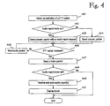
- FIG. 4 An example of the operation of a sending user terminal (a calling party), e.g. MS, is illustrated in Figure 4 .
- the user pushes the PTT pressel 306 which is detected by the controller 305 (step 401).
- the controller 305 signals a speech item request to the mobile RAN, thereby asking a dedicated radio bearer for the duration of the entire speech item.
- the mobile RAN grants the uplink bearer (e.g. a dedicated packet data channel and the physical time slot).
- the mobile RAN acknowledges the allocation of the uplink bearer, the mobile starts sending data there through.
- the controller checks from an internal memory whether an audio report mode is set in the user terminal (step 402). Examples of how the user can set audio report mode are described below.
- the first packet to be sent is an RTP message containing the talking party mnemonic identifier. If the audio report mode is set, the leader packet also contains an audio report request (step 403). Examples of a leader packet with audio report request are described below. If the audio report mode is not set, the leader packet is sent without the audio report request (step 404). The leader packet is followed by voice stream packets (audio packets, such as VoIP packets) until the PTT pressel is released (steps 405 and 406). When the controller 305 detects that the PTT 306 is released, the controller 305 sends a trailer packet (step 407) and the uplink voice bearer is released.
- voice stream packets audio packets, such as VoIP packets
- the speech item is divided into three parts: a leader RTP packet, audio RTP packet(s) and a trailer RTP packet.
- the leader packet contains embedded signalling for the call.
- the audio packet may have no signalling but only the parts of the speech.
- the trailer packet is the last part of the speech item and contains some embedded signalling. In an embodiment of the invention, no trailer packet is sent but the called party detects the end of the speech item otherwise.
- the controller checks whether the audio report mode is set (step 408). If not, the process ends. If the audio report mode is set, the controller 305 waits for the audio report(s) and stores received audio report(s) (step 409). An example of an audio report is described below.
- the controller 305 displays the report(s) or information derived from it/them on the display (step 410).
- the displayed information typically contains at least information indicating the identity of the recipient(s) of the speech item. Thus, the user can see which group members received the previous speech item(s).
- the leader RTP packet and the VoIP packets are routed to the U-UPF of the user on the basis of the active GPRS context.
- the U-UPF of the calling party sends packets to the U-UPF of the called party.
- the downlink bearer in the radio interface of the mobile network is allocated by the SGSN when it detects an IP packet travelling via an existing context to a mobile station MS. Firstly, the SGSN pages the MS if it is in a STANDBY state. After receiving an acknowledgement from the MS, the SGSN requests that the RAN (e.g. the GSM BSS) allocates a dedicated radio bearer, and after the allocation the SGSN starts sending packets (e.g. in LLC frames) to the RAN. The RAN sends the packets (e.g. in radio blocks) to the MS.
- the RAN e.g. the GSM BSS
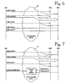
- the leader RTP packet and the following VoIP packet can be routed via any communication system between the calling party and the receiving party or parties, as illustrated in Figures 6 and 7 .
- the transit network has no part in the inventive functionality.
- the intermediate communication system(s) only provide(s) a communication "pipe" between the end users.
- FIG. 5 An example of the operation of a receiving user terminal (a called party), e.g. MS, is illustrated in Figure 5 .
- the controller 305 observes that a leader packet is received (step 501).
- the controller 305 checks whether the received leader packet contains an audio report request (step 502). If the request is not present, the controller 305 proceeds to receive next packet (i.e. VoIP packet). However, if the audio report request is present, the controller sets an audio report mode. In the audio report mode, the controller process of the received audio packets so that it contains the information required for building up the audio report as requested. Then the controller 305 receives and processes audio packets until a trailer packet is received or the end of speech item is otherwise detected, e.g.
- the controller 305 checks whether the audio report mode is set (step 507). If not, the process ends. It the audio report mode is set, the controller creates the audio report as requested and sends the report to the calling party (step 508).
- the report may be sent as embedded signalling in the user plane, e.g. in a packet similar to the leader packet, or as outband signalling in the control plane, e.g. SIP signalling.
- the audio reports are forwarded through the communication system to the calling party without any processing by the communication system 12, as illustrated in Figure 6 .
- This allows the present invention to be implemented in the user terminals only, and therefore no special infrastructure functions are needed for the invention.
- the disadvantage is the extra transmission capacity needed in both uplink and downlink directions.
- the communication system 12 intercepts the group call related audio processing reports from the receiving parties and sends only one combined report to the calling party, as illustrated in Figure 7 .
- These embodiments require less transmission capacity but, on the other hand, they require a special functionality in the infrastructure.
- the entity collecting the reports may be the bridge 10 or the U-UPF of the calling party if the embedded signalling is employed for the reports. If the outband signalling, such as SIP, is employed, the entity collecting the reports may be the call processing server 11 or the U-CPF of the calling party.
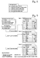
- the user can set the user terminal in an audio report mode from the user interface, e.g. using a specific button or a menu.
- an audio report activation menu shown in Figure 8 may be displayed to the user.
- the user can select between several different report options which affect the contents of the report request, the contents of the audio report, and/or the information displayed to the user.
- the options selectable for the content of the audio report include:
- the terminal always sends a request for the audio report when the report mode is active.
- the audio report mode is active until the user deactivates it.
- the mode is inactive as a default, and the mode must be activated after switching on the terminal, for example.
- acknowledgement reports are illustrated in Figure 9 .
- the sending user presses the PTT to start the speech item and a respective acknowledgement report request is transmitted to the recipients as described above.
- the sending user ends the speech item and the recipients transmit acknowledgement reports as described above.
- the mobile station of the sending user creates and displays to the user an acknowledgement report which may have a format shown in the rightmost part of Figure 9 .
- the report may include the name of the report, e.g. "Acknowledgement report", the name of the group, e.g.
- the "Design team” and various fields relating to the recipient group members, such as "Member” field, "Status” field, and "Quality” field.
- the “Member” field indicates the names of the group recipients.
- the “Status” field contains an indicator indicating whether the reception of the previous speech item was successful (the indicator +) or unsuccessful (the indicator -) for the specific recipient, while an empty status field indicates that no report was received from the recipient.
- the "Quality” field gives a value representing the quality of the end-to-end connection, e.g. the number of invalid packets/total number of packets *100.
- the report 1 indicates that all group members received the first speech item successfully.
- the report 2 indicates that the next speech item was successfully received by John, Adam and Eve but no report was received from Mary and Matt.
- the report 3 indicates that the third speech item was successfully received by all recipients except Matt.
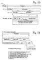
- FIG 10 illustrates an example of an RTP packet 100 encapsulated into the payload of an UDP packet 110.
- the UDP 110 packet is further encapsulated into the IP payload of the IP packet 120.
- This approach is in accordance with the RTP/UDP/IP protocol stack commonly used in the VoIP world for real-time audio data transmission.
- the RTP packet 100 includes the RTP header 101 and the RTP payload 102.
- the RTP header 101 is basically in accordance with the RFC 1889.
- the RTP header 101 includes the following fields and parameters, V, P, X, CC, M, PT, sequence number, time stamp, synchronization source (SSRC) identifier, contributing source (CSC) identifiers, etc.
- the field PT having a value 105 indicates that the RTP payload 102 contains embedded control signals for the PoC.
- Figure 11 illustrates an example of an RTP leader packet containing an acknowledgement report request according to the present invention.
- the value of the field PT is 105, indicating that the RTP payload contains embedded control signals.
- the control signal includes a signal identifier field, a signal length field, and a signal field.
- the value of the signal identifier field is 126, indicating that the signal is an acknowledgement report request.
- the signal length field indicates that the length of the signal is one byte.
- the signal ARR Acknowledgement Report Request
- the one-bit fields V, P, I, A, and F correspond to the options selectable in the audio report request menu shown in Figure 8 .
- the respective option is inactive (OFF), and when the value is 1, the respective option is active (ON).
- the parameter r is reserved for a future use and has a default value 0.
- the sending MS sets the values of the parameters according to the user selection in the audio report request menu, and transmits the leader packet with the ARR in the beginning of the each speech item, for example. Upon receiving the leader packet with the ARR, the receiving MS configures the acknowledgement mode in accordance with the values of the received parameters.
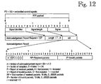
- Figure 12 illustrates an example of an acknowledgement report packet sent as an embedded control signal in the RTP payload.
- the value of the field PT is 105, indicating that the RTP payload contains embedded control signals.
- the value of the signal identifier field is 127, indicating that the signal is an acknowledgement report AR.
- the signal length has a value 1-5, depending on how many of the acknowledgement report options are active.
- the acknowledgement report field AR contains the parameters A, V, P, I, r, RP, and IP.
- the two-bit field A indicates the version of the acknowledgement report, e.g. the value 00 indicates the version 1.0.
- the 16-bit field RP contains the total number of received packets, being capable of indicating 0...65535 speech packets.
- the 16-bit field IP indicates the number of invalid packets, being capable of indicating 0...65535 speech packets.
- the one-bit fields r are reserved for a future use and have a default value 0.
- the receiving MS sends the RTP packet to the sending MS after each speech item.
- the sending MS analyzes the contents of the received acknowledgement report(s) and creates and displays a report of a type shown in Figure 9 , for example.
- a real-time video item can be transported with the Real-Time Transport Protocol (RTP) in a similar manner as described for the real-time audio (speech) above.
- RTP Real-Time Transport Protocol
- a real-time multimedia items containing, for example, real-time audio and video can be transported using the principles described above.
- the reporting is made using graphical presentations, such as symbols representing the recipients.
- the successful/unsuccessful reception of the real-time data item may be indicated by colour, type and/or shape of the symbol, for example.
- the successful/unsuccessful reception is indicated by an audible alarm or an oral announcement, such as "Matt failed to acknowledge" or "Everyone acknowledged”.
Abstract
Description
- The invention relates to communications systems, and especially to real-time data (two-party or multi-party) communication in communications systems.
- Background of the Invention
- The most common call type is a call established between two parties for one-to-one communication. The standard way to set up a two-party call requires explicit control plane signalling that allows the call parties to establish a channel where the audio data can be transferred and to negotiate the communication capabilities; for example, the audio codec and the relative compression rate can be determined in this phase. Afterwards the actual voice communication can start and the audio data can be transmitted by the call parties.
- Voice over Internet Protocol (VoIP) enables a speech communication over an IP connection. The Session Initiation Protocol (SIP, RFC 2543) is conventionally used for call establishment in "VoIP" based communication systems.
- A mobile communications system refers generally to any telecommunications system which enables communication when users are moving within the service area of the system. A typical mobile communications system is a Public Land Mobile Network (PLMN). Often the mobile communications network is an access network providing a user with wireless access to external networks, hosts, or services offered by specific service providers.
Byung-Won On et al. "A Reliable Multicast Protocol in Networks With Mobile Hosts", IEEE - ISBN 0-7695-0819-7, discloses a method for managing and buffering multicast messages in network elements based on the message acknowledgements received from the targeted mobile hosts. The method seeks to avoid an overload in network elements.
Similarly to Byung-Won On et al. referenced above, Byung-Won On et al. 'A Hierarchical Ack-Based Protocol for Reliable Multicast in Mobile Networks', IEEE - ISBN 0-7695-0777-8 relates to a method for avoiding an overload of network elements in a multicast communication.
US 5809018 discloses a radio system providing a mobile subscriber with the possibility to select a group call in which the subscriber will participate with all ongoing group calls in current location of the subscriber while the subscriber station is already participating in another group call. This is achieved by sending information on other ongoing group calls to a subscriber station while the subscriber station is already participating in a first group call. This information may be displayed to the subscriber who can switch to a new group call if decided. The subscriber station also transmits to the radio system an acknowledgement indicating that the subscriber station has started to participate in a certain group call.
US 6181685 discloses a solution for providing reverse power control for group call communications in CDMA systems. The solution is based on utilizing a power adjustment channel for the group call. The identification of the at least one power adjustment channel is sent to at least some of the subscriber units in the group.
HONG Y. S. ET AL.: 'Distributed real-time simulation of the group manager executing the multicast protocol RFRM', PROCEEDINGS INTERNATIONAL SYMPOSIUM ON OBJECT-ORIENTED REAL-TIME DISTRIBUTED COMPUTING, 29 April 2002, pages 173-176 presents a group membership manager executing the multicast protocol RFRM (Release-time based Fault-tolerant Real-time Multicast) which is based on the idea of attaching the official release time to each group view-send message. The group membership manager maintains a group view, i.e. the current list of active group members and sends the new group view to its members whenever a view change is occurred. In the proposed approach the client application does not send view-ack message to the group membership manager. Using the proposed scheme, it is possible to reduce the delay of completing the group view change event.
RING S. :'Digital advanced wireless services (DAWS)-the ETSI standardization of the next generation mobile platform for public safety, law enforcement and non-tactical military' EUROCOMM 2000, presents future development and standardization of a new mobile broadband technology, DAWS. The basic idea is to develop a set of standards enabling support of the fast growing demand for professional mobile applications that require high bit rates. The requirements for DAWS are discussed regarding services and applications to be provided therein.
WO 02 01780 A2
US-A-5 375 068 discloses a video teleconferencing method and apparatus for computer workstations connected by a digital data network includes a transmission source portion for a local workstation to send audio and video teleconference data across the network to one or more remote workstations, and, a receiver for the local workstation to receive audio and video teleconference data back from the remote workstations. A slave process on the remote workstation issues a frame acknowledge message for each frame of video data successfully received from the local workstation at the remote workstation. - Professional mobile radio or private mobile radio (PMR) systems are dedicated radio systems developed primarily for professional and governmental users, such as the police, military forces, oil plants, etc. PMR services are offered via dedicated PMR networks built with dedicated PMR technologies. This market is divided between several technologies - analog, digital, conventional and trunked - none of which has a dominating role. TETRA (Terrestrial Trunked Radio) is a standard defined by ETSI (European Telecommunications Standards Institute) for digital PMR systems.
- One special feature offered by the PMR systems is group communication. The term "group", as used herein, refers to any logical group of three or more users intended to participate in the same group communication, e.g. a call. Group communication with a push-to-talk feature is one of the essential features of any PMR network. Generally, in group voice communication with a "push-to-talk, release-to-listen" feature, a group call is based on the use of a pressel (PTT, push-to-talk switch) in a telephone as a switch: by pressing a PTT the user indicates his desire to speak, and the user equipment sends a service request to the network. The network either rejects the request or allocates the requested resources on the basis of predetermined criteria, such as the availability of resources, priority of the requesting user, etc. At the same time, a connection is established also to all other active users in the specific subscriber group. After the voice connection has been established, the requesting user can talk and the other users can listen on the channel. When the user releases the PTT, the user equipment signals a release message to the network, and the resources are released. Thus, the resources are reserved only for the actual speech transaction or speech item, instead of reserving the resources for a "call". One interesting advantage of the push-to-talk communication, or more generally speech-item-by-speech-item communication, is a short call setup time, which also makes such speech communication attractive to several other types of users.
U.S. Patent 6,141,347 discloses a wireless communications system which uses multicast addressing and decentralized processing in group calls. - A problem with such item-by-item communication is that a strict discipline or protocol is required from the parties in the speech communication, or other type of real-time data communication. Further, especially in group communication, it is difficult to know which the parties of the communication are at each specific moment, and therefore the communication must include spoken questions and acknowledgements.
- An object of the invention is to provide a new way to control parties in an item-by-item real-time data communication.
- This object of the invention is achieved by methods, systems and terminals as defined in the attached independent claims. Various embodiments of the invention are defined in the attached dependent claims.
- In the present invention, each receiving user terminal acknowledges the reception of a real-time data item by sending a real-time data item acknowledgement report after the end of the item. In an embodiment of the invention, the acknowledgement report may be sent after a successful reception of real-time data item, unsuccessful reception of real-time data item or in both cases, depending on the implementation and/or the user's selection. In an embodiment of the invention, the report may also contain information relating to the quality of the connection. In an embodiment of the invention, the receiving terminal sends an acknowledgement report only in response to a specific request sent by the sending user terminal from which the real-time data item originated, and no report is sent otherwise. This embodiment allows unnecessary reports to be avoided if the sending party is not interested in them. In another embodiment of the invention, the report is sent as a default. In an embodiment of the invention, each acknowledgement report is forwarded over a communication system to the sending user terminal from which the real-time data item originated. In this embodiment, no extra functionality is needed in the communication system infrastructure for the present invention. In another embodiment of the invention, a communication system infrastructure collects acknowledgement reports from a plurality of receiving user terminals and sends a combined acknowledgement report to the sending user terminal from which the real-time data item originated. This embodiment requires extra functionality in the communication system infrastructure for the invention but, on the other hand, requires less transmission capacity. When the sending user terminal receives the acknowledgement report(s) after the real-time data item has ended, it may display information which indicates to a sending user which terminal(s) or user(s) were receiving the previous real-time data item. Thus, the present invention alleviates the problem of knowing who actually received the transmitted real-time data. With the present invention, the sending user automatically knows who received the previous real-time data item. Consequently, the users are no longer required to give this information themselves, as is the case in the prior art systems.
- In an embodiment of the invention, embedded (i.e. implicit) signalling in a real-time data traffic is employed for transferring a request for an acknowledgement report and/or the acknowledgement report(s). Embedded signalling makes it unnecessary to reserve another bearer for the control signalling, which saves network resources and allows a short connection setup time to be achieved. In another embodiment, the acknowledgement report(s) is transferred using outband signalling, such as SIP signalling.
- In some embodiments of the invention, packet mode speech communication is employed, such as Internet Protocol (IP) packets or VolP speech communications.
- In an embodiment of the invention, the embedded signalling comprises sending a leader packet from a sending user terminal to at least one receiving user terminal. The leader packet starts a real-time data item. In an embodiment of the invention, the leader packet is employed for requesting the receiving user terminal(s) to send an acknowledgement report when the respective real-time data item has ended. After the leader packet, audio packets that may contain no signalling but may contain only part of the real-time data item are sent. A trailer packet is the last part of the real-time data item and may be used by the receiving user terminal(s) to detect the end of the real-time data item.
- In the following, the invention will be described in greater detail by means of preferred embodiments and with reference to the accompanying drawings, in which
-
Figures 1 and 2 show block diagrams illustrating examples of a communication system whereto the present invention can be applied; -
Figure 3 is a simplified block diagram illustrating an example of a user terminal whereto the present invention can be applied; -
Figure 4 is a flow diagram illustrating an example of the operation of a user terminal from which a speech item originates; -
Figure 5 is a flow diagram illustrating an example of the operation of a user terminal which receives a speech item; -
Figures 6 and 7 are messaging charts illustrating two examples of transferring a leader packet, audio packets, trailer packet and acknowledgement reports through a communication system; -
Figure 8 shows an example of an acknowledgement report activation menu that may be displayed to the user, -
Figure 9 shows an example of an acknowledgement report displayed to the user; -
Figure 10 shows an example of an RTP packet encapsulated into UDP and IP packets, -
Figure 11 shows an example of an RTP leader packet containing an acknowledgement report request; -
Figure 12 shows an example of an RTP packet containing an acknowledgement report. - The present invention is applicable to any communications system allowing real-time data communication between end users on the item by item basis. The real-time data may include real-time audio (e.g. speech), real-time video, or any other real-time data, or combination thereof, i.e. real-time multimedia.
- The present invention is especially applicable to any communications system allowing packet-mode real-time data communication, such as IP packet communication between end users. Thus, the real-time data communication may be carried out between end user terminals over the Internet, for example.
- The present invention offers a significant improvement for packet-mode speech communications. In some embodiments of the invention, the IP voice communication method employed is the Voice over IP (VoIP), but the invention is not limited to this particular method.
- One application field of the invention is in mobile packet radio communications systems. In the following, embodiments of the invention will be described by means of a GPRS type packet radio service and the UMTS or GSM system, without limiting the invention to these communication systems.
-
Figure 1 illustrates an example wherein a packet mode speech communication service is embodied within a server based core network (CN) with different control and user-plane's logical entities serving the subscribers connected thereto. This concept and architecture is illustrated in more detail in the copendingU.S. patent applications 09/835,867 and09/903,871 - The
communication system 12 may be a mobile radio access network (RAN) which provides the IP packet data service which may be based on a GPRS architecture utilizing a second generation (2G) or third generation (3G) radio access technology. Similarly, any communication system supporting a packet mode voice communication can be employed instead of the mobile network described above. It should be appreciated that the type of the underlying network layer (i.e. "the access network") is not essential to the basic invention. Some embodiments of the invention can be embodied in the end-user terminals without any supporting functionality on the network side. - In
Figure 1 , a packet mode voice communication layer 13 (or a core network CN) is provided on top of the mobile network in order to provide communication services to the user terminals through the communications system, e.g. mobile network. This layer can be called a Push-to-talk over Cellular (PoC) layer. Conceptually, the packet modevoice communication layer 13 may comprise a pair of basic logical entities, abridge 10 and a call processing server (CPS) 11. Thebridge 10 and theCPS server 11 run packet mode voice communication applications, which communicate with the packet mode voice communication application(s) in the user terminals over the IP connections provided by the IP communication system. This communication includes both signalling packets and voice (group or one-to-one) communication packets. - The
CPS 11 may be responsible for control-plane management of the packet mode voice communications. Its important role may require various functionalities, managing the user activity and creation and deletion of logical user-plane connections with an appropriate control protocol, such as Session Initiation Protocol SIP, and management of the user profiles (call rights, group active membership, scanning settings, etc.); SIP Proxy/Location Server - providing user location and routing functionalities of SIP signalling; SIP Registrar - for user registration/authentication; and Media Gateway Controller - controlling the network entities (PoC bridges) involved in the IP layer data distribution according to the group & user specific information (membership, rights, scanning settings, etc.). However, as used herein, the common term CPS refers to all possible functionalities of the CPS. - Referring to a further embodiment shown in
Figure 2 , since the PMR management requirements can be divided into group and user specific ones, there may be two kinds of CPS. The SIP sessions for group communications are handled by a Group Control Plane Function (G-CPF) 23 (e.g. in a server). When a user connects to a group, the G-CPF 23 takes care of the relative SIP invitation transaction and performs the proper mapping settings between the user's recipient and the network entities responsible for the relative traffic distribution. The User - Control Plane Function (U-CPF) 22 (e.g. a control plane proxy server) is basically the control plane interface between the IP network and the user (inFigure 2 , U-CPF22 is provided for the MS1 andU-CPF 27 is provided for MS2). By this network entity, the users log on to the system and negotiate their operational settings (scanning settings, selected group etc.). It handles the user's profile and manages his or her one-to-one calls. It should be appreciated that this is just a logical separation, and both kinds of CPS can be situated in the same computer. Separating G-CPF and U-CPF enables users to join PoC groups handled by G-CPF in different intranets or in mobile networks of different operators and IP domain. The division also brings scalability by allowing, in practice, an infinite number of groups or users in the system. A Subscriber and Group Management Function (SGMF) 25 may be provided for managing the subscriber and group data. The end users or other users may connect to theSGMF 25 using any communication method. In an embodiment of the invention, the control interface is WWW based and accessible using a standard web browser. - Referring again to
Figure 1 , thebridge 10 is responsible for the real-time distribution of VolP packets to the users' terminals according to their group memberships, their scanning settings and eventual pre-emption or emergency cases. Each bridge forwards traffic only between valid connections programmed by the CPS. Thebridge 10 may perform one or more of the following functionalities. - Input checking: to identify and authenticate the traffic source (optionally the mnemonics in the leader RTP packet, which will be discussed below, have to be processed here). Input checking may also include actions to perform and support security procedures.
- Input filtering: to manage that only one talker talks in a group at a time (i.e. grants a speech item), and optionally to give priority to higher priority voice items.
- Multiplication: after the filtering process, the
bridge 10 has to check the active members of the group to which the traffic is destined and generate from the incoming packet a "downlink" packet for each active member. - Scanning filtering: to select from among the multiple incoming traffic streams destined to the same user the one which has to be forwarded to his recipient according to the user's scanning settings.
- Again, since input filtering and multiplication are group specific processes, while input checking and scanning filtering are user specific, the bridge may comprise two logical parts, as illustrated in
Figure 2 . - Firstly, a Group - User Plane Function (G-UPF) G-UPF 21 (e.g. in a server) is a network entity to which group members' audio packets are sent (through their U-UPF) and where the input filtering and multiplication processes are performed. To each new group, the G-
CPF 23 assigns a single G-UPF 21 according to load balancing criteria which distribute the traffic between the G-UPFs as evenly as possible. - The User - User Plane Function (U-UPF) U-UPF20 (e.g. in a server) performs the input checking and scanning processes for the individual subscribers assigned to it by the U-CPF 22 (In
Figure 2 , the U-UPF 20 is provided for the MS1 andU-UPF 26 is provided for MS2). For security purposes, the U-UPF 20 may have security associations for each mobile terminal it handles. The U-UPF 20 hides the network complexity from the mobile terminals, so the user only has to send all of his user plane traffic to this unit that afterwards forwards it according to the mapping settings of theproper U-CPF 22. In this way, there is no need to establish secure channels between each user and all the IP network entities which only have to trust the U-UPF 20 from which they receive packets. - As for the Control Plane elements, this logical splitting does not necessarily require a physical separation between the G-UPF and the U-UPF implementations, and thus they may be located in the same computer.
- The U-CPFs 22 and 27, which are responsible for managing the sessions of the users, may require specific control plane signalling. ETSI 3GPP (European Telecommunications Standards Institute, 3rd Generation Partnership Project) specifications include IP based voice communications in a so-called all-IP network. Such an all-IP network enables also voice communication in IP network (voice over IP, VoIP). For VoIP, call control signalling is specified, such as the Session Initiation Protocol (SIP), which is defined in the RFC 2543.
- However, some other IP session protocol can be used instead. For example, Megaco (defined in RFC 3015) may be used by the U-CPFs 22 and 27 to control the U-UPFs 20 and 26 involved in traffic distribution of the IP layer. However, some other corresponding protocol for controlling the switching of the user-plane elements may be used instead. Still further, the RTP (Real Time transport Protocol, defined in RFC1889)) may be chosen to handle the transfer in the preferred embodiment, and QoS mechanisms may be used to handle the voice packet (VoIP) delivery.
- The Real-Time Transport Protocol (RTP) developed by the IETF to support the transport of real-time streams for audio communications over packet networks may be used on top of the UDP in order to avoid the delays introduced by more reliable transport protocols (not required in this context), such as the TCP. With the RTP and latency buffering at the receiving endpoint, the timing (jitter problem), packet ordering, synchronization of multiple streams, duplicate packet elimination and continuity of the streams can be handled.
- The SIP protocol defines signalling messages for call control, user location and registration, and these may be used to handle the specific voice communications and the relative participating users (establishment, joining and tear down of a call session, user's log on to the services, user's profile negotiation, etc).
- For each communication, a SIP session is established and managed by the CPS handling it (G-
CPF 23 andU-CPF 22/27 for group and one-to-one communications respectively). When a user wants to become an active member of a group, he has to join the corresponding session. For one-to-one calls, the PoC U-CPFs maintain one session between participating U-CPFs for each one-to-one call. - All the user's outgoing and incoming traffic has to go through the U-UPF 20/26 that has been assigned to the user. In particular, in the uplink the user's traffic is checked by his
U-UPF 20/26 and forwarded to the G-UPF 21 handling the group to which the traffic is destined or, in the case of one-to-one communication, to the U-UPF 20/26 handling the called party. - In the downlink, the traffic is then distributed to the destination users' U-UPFs 20/26 (by packet multiplication in the G-
UPF 21 in the case of group communication, packets are multiplied and forwarded to each U-UPF which is serving active members in the group). In the U-UPF, the users' scanning processes are performed and traffic is multiplied and forwarded to each user that listens to the group according to his current scanning settings. - This PoC approach is access independent, which means that it can run on top of GSM, WCDMA, WLAN or equivalent technologies as long as these are able to support the always-on VoIP bearers. The IP layer's audio distribution uses standard VoIP mechanisms (such as the RTP), while specific internet protocols or interfaces will be used to connect supplementary network entities, such as Subscriber and Group Management Function (SGMF) 25, a Domain Name Server (DNS) 24, WWW/WAP (World Wide Web/Wireless Application Protocol) and security management servers. Each network entity is obviously associated with at least one IP address by which the IP packets are transferred and routed, but the role of the network elements have also to be defined from the SIP's point of view. Each MS is a SIP User Agent (UA), and thus each one has a SIP address (URL) which normally is "usemame@hostname" where the hostname can be, but not necessarily is, associated with the U-CPF 22/27 in which the MSs have to register. This U-CPF 22/27 may act as a Registrar, Location and Proxy SIP server in order to allow the reachability of the MSs under his control and to support the SIP signalling routing. The G-
UPFs 21 and U-UPFs 20/26, which are exclusively involved in the audio data distribution, do not have a role in the actual SIP mechanisms and the core network is simply seen as a single IP network link. At the SIP signalling level, URLs are used for user and group identification. The URLs can be sip: URLs as defined in the RFC 2543, tel: URLs representing telephone numbers as defined in the RFC 2806, or any other URL formats. The REGISTER method is used with a sip: URL, that is, SIP URL is the user main identity in PoC system. Dialling of users with a private numbering plan number (only) is possible using the tel: URL in the To: header field (sip: URL must have the host portion present at all times). A secondary identity can be used for example for addressing the b-party for one-to-one calls if the b-party is from the same Virtual Private Network (VPN). Groups may be addressed with sip: URLs, where the group name is used in place of the user name, and the host managing the group (exact G-CPF, if known) in the host portion. - The user equipment, or mobile station MS, may have a packet mode voice communication application on a user layer on top of the standard protocol stack used in the specific mobile communications system. The SIP and RTP protocols employ the underlying TCP, UDP and IP protocols, which further employ the physical layer resources, such as the radio resources. It can be assumed that at least in the users' terminals the IPv6 is implemented, while in some core network entities it could be required to support the IPv4 also (dual IPv6/v4 stack) in order to assure the interoperability with eventual sub-networks still using it. The MS, when the packet mode voice communication mode is selected by the user, sets up two GPRS contexts: a) one to be used for control plane signalling (SIP/UDP/IP), b) one for real-time audio streams (RTP/UDP/IP) with conversational IP quality class or the like, and sufficient header compression over the radio path. The RTP/UDP/IP protocol stack is commonly used in the VoIP world for real-time audio data transmission, and it is thus selected for the user-plane in the preferred embodiment of the invention as well. If a mobile or the mobile network does not support two simultaneous contexts, the mobile may clear down the RTP connection for the duration of the SIP signalling transaction. The MS must always maintain the contexts for the
bridge 10 when the packet mode voice communication mode is on. The SIP context is also preferably on all the time, but if this causes problems to network capacity, the SIP context can be set up also for the duration of signalling transactions. In such a case, the cellular network may support the network-initiated context set up. The SIP sessions are signalled in power on or in packet mode voice communication mode activation. The SIP sessions are always on and thus no SIP signalling is needed for packet-mode voice items. All voice is transmitted after PTT activation or any other suitable manual or voice activation (such as voice activity detection, VAD) via the existing contexts. - An example of a possible implementation of a mobile station MS is illustrated in a simplified block diagram shown in
Figure 3 . AnRF part 301 represents any radio frequency function and hardware required by a specific air interface employed. The actual implementation of theRF part 301 is not relevant to the present invention. Abaseband signal processing 302 represents any baseband signal processing required in any specific implementation, such as an analog-digital (A/D) conversion of the analogue speech signal from themicrophone 303, vo-encoding, IP packet building, frame building, deframing, IP packet debuilding, vo-decoding, a digital-analog (D/A) conversion of the received digital speech signal into an analog signal applied to aloudspeaker 304. TheRF part 301 and thebaseband signal processing 302 are controlled by acontroller 305. Thecontroller 305 controls the signalling, both outband (SIP) and embedded, as well as IP packet building and debuilding. Start and stop of the speech items are set by thePTT switch 306 which can be replaced by any user-operated device, e.g. a voice activity detector (VAD). Such alternative mechanisms for starting and ending a speech item instead of the PTT are obvious to a person skilled in the art. A user interface may include adisplay 307 and akeyboard 308. It should be appreciated that the blocks illustrated inFigure 3 are functional blocks which can be implemented in a variety of different circuit configurations. For example, the baseband processing and the controller may implemented in a single programmable unit (e.g. a CPU or a signal processor) or in a plurality of units. The operation according to the present invention is primarily related to the controller part of the MS, and the basic invention may be implemented as program modifications in the control program of the MS, for example. It should also be appreciated that the present invention is not intended to be restricted to mobile stations and mobile systems but the terminal can be any terminal having a speech communication capability. For example, the user terminal may be a terminal (such as a personal computer PC) having Internet access and a VoIP capability for voice communication over the Internet. - However, the operation of the present invention is illustrated in connection with the PoC architecture described above, without restricting the invention to this specific system. When a call party has a logical connection, the actual communication path, including the channel resources at the sending and receiving ends, needs to be opened and the resources to be reserved only for the duration of the talk item. Call set-up signalling, authentication, agreement on encryption keys and negotiation over service parameters are not needed in the resource reservation phase because the logical connections already exist, but the physical resources are reserved and opened by using the signalling procedures. Thus, short connection set up times can be achieved. In an embodiment which uses VoIP based communication, the inventive concept means that embedded signalling in the Real-time Transport Protocol (RTP) packets will suffice without time consuming SIP signalling. Specific RTP packets with relative payload types are defined. In these special-purpose packets, the content of payloads and/or the values in the "payload type" field in the RTP header are used as embedded signalling. More generally, the same type of embedded signalling can also be applied to another type of real time voice packets in the IP or another protocol environment.
- An example of the operation of a sending user terminal (a calling party), e.g. MS, is illustrated in
Figure 4 . The user pushes the PTT pressel 306 which is detected by the controller 305 (step 401). Thecontroller 305 signals a speech item request to the mobile RAN, thereby asking a dedicated radio bearer for the duration of the entire speech item. The mobile RAN grants the uplink bearer (e.g. a dedicated packet data channel and the physical time slot). When the mobile RAN acknowledges the allocation of the uplink bearer, the mobile starts sending data there through. Firstly, the controller checks from an internal memory whether an audio report mode is set in the user terminal (step 402). Examples of how the user can set audio report mode are described below. The first packet to be sent is an RTP message containing the talking party mnemonic identifier. If the audio report mode is set, the leader packet also contains an audio report request (step 403). Examples of a leader packet with audio report request are described below. If the audio report mode is not set, the leader packet is sent without the audio report request (step 404). The leader packet is followed by voice stream packets (audio packets, such as VoIP packets) until the PTT pressel is released (steps 405 and 406). When thecontroller 305 detects that thePTT 306 is released, thecontroller 305 sends a trailer packet (step 407) and the uplink voice bearer is released. Thus, in this embodiment, the speech item is divided into three parts: a leader RTP packet, audio RTP packet(s) and a trailer RTP packet. The leader packet contains embedded signalling for the call. The audio packet may have no signalling but only the parts of the speech. The trailer packet is the last part of the speech item and contains some embedded signalling. In an embodiment of the invention, no trailer packet is sent but the called party detects the end of the speech item otherwise. The controller checks whether the audio report mode is set (step 408). If not, the process ends. If the audio report mode is set, thecontroller 305 waits for the audio report(s) and stores received audio report(s) (step 409). An example of an audio report is described below. Thecontroller 305 displays the report(s) or information derived from it/them on the display (step 410). The displayed information typically contains at least information indicating the identity of the recipient(s) of the speech item. Thus, the user can see which group members received the previous speech item(s). - The leader RTP packet and the VoIP packets are routed to the U-UPF of the user on the basis of the active GPRS context. The U-UPF of the calling party sends packets to the U-UPF of the called party. The downlink bearer in the radio interface of the mobile network is allocated by the SGSN when it detects an IP packet travelling via an existing context to a mobile station MS. Firstly, the SGSN pages the MS if it is in a STANDBY state. After receiving an acknowledgement from the MS, the SGSN requests that the RAN (e.g. the GSM BSS) allocates a dedicated radio bearer, and after the allocation the SGSN starts sending packets (e.g. in LLC frames) to the RAN. The RAN sends the packets (e.g. in radio blocks) to the MS.
- Similarly, the leader RTP packet and the following VoIP packet can be routed via any communication system between the calling party and the receiving party or parties, as illustrated in
Figures 6 and 7 . It should be appreciated that in some embodiments of the invention, the transit network has no part in the inventive functionality. The intermediate communication system(s) only provide(s) a communication "pipe" between the end users. - An example of the operation of a receiving user terminal (a called party), e.g. MS, is illustrated in
Figure 5 . Thecontroller 305 observes that a leader packet is received (step 501). Thecontroller 305 checks whether the received leader packet contains an audio report request (step 502). If the request is not present, thecontroller 305 proceeds to receive next packet (i.e. VoIP packet). However, if the audio report request is present, the controller sets an audio report mode. In the audio report mode, the controller process of the received audio packets so that it contains the information required for building up the audio report as requested. Then thecontroller 305 receives and processes audio packets until a trailer packet is received or the end of speech item is otherwise detected, e.g. by not receiving a new packet from the same calling party (steps controller 305 checks whether the audio report mode is set (step 507). If not, the process ends. It the audio report mode is set, the controller creates the audio report as requested and sends the report to the calling party (step 508). The report may be sent as embedded signalling in the user plane, e.g. in a packet similar to the leader packet, or as outband signalling in the control plane, e.g. SIP signalling. - In some embodiments of the invention, the audio reports are forwarded through the communication system to the calling party without any processing by the
communication system 12, as illustrated inFigure 6 . This allows the present invention to be implemented in the user terminals only, and therefore no special infrastructure functions are needed for the invention. The disadvantage is the extra transmission capacity needed in both uplink and downlink directions. - In some other embodiments of the invention, the
communication system 12 intercepts the group call related audio processing reports from the receiving parties and sends only one combined report to the calling party, as illustrated inFigure 7 . These embodiments require less transmission capacity but, on the other hand, they require a special functionality in the infrastructure. The entity collecting the reports may be thebridge 10 or the U-UPF of the calling party if the embedded signalling is employed for the reports. If the outband signalling, such as SIP, is employed, the entity collecting the reports may be thecall processing server 11 or the U-CPF of the calling party. - In an embodiment of the invention, the user can set the user terminal in an audio report mode from the user interface, e.g. using a specific button or a menu. For example, an audio report activation menu shown in
Figure 8 may be displayed to the user. The user can select between several different report options which affect the contents of the report request, the contents of the audio report, and/or the information displayed to the user. In the example shown inFigure 8 , the options selectable for the content of the audio report include: - indicate the verdict of reception, e.g. OK/FAILED. This gives ON/OFF (two state) information on the success of reception.
- indicate the total number of received packets. This information represents the quality of the communication, providing a kind of QoS value for the end-to-end connection
- Indicate the number of invalid packets. This information also represents the quality of the communication, providing a kind of QoS value for the end-to-end connection
- Send report after successful reception. For example, a report is sent after reception of a trailer packet. It should be noted that successful reception may contain invalid packets.
- Send report after reception failure. The reception may be determined to be unsuccessful if the number of invalid packets exceeds a threshold or a trailer packet is missing, for example.
- The terminal always sends a request for the audio report when the report mode is active. In an embodiment of the invention, the audio report mode is active until the user deactivates it. In another embodiment, the mode is inactive as a default, and the mode must be activated after switching on the terminal, for example.
- Examples of acknowledgement reports are illustrated in
Figure 9 . In the top left corner there is an acknowledgement report request similar to that shown inFigure 8 . All acknowledgement options have been selected. The sending user presses the PTT to start the speech item and a respective acknowledgement report request is transmitted to the recipients as described above. The sending user ends the speech item and the recipients transmit acknowledgement reports as described above. On the basis of the acknowledgement reports, the mobile station of the sending user creates and displays to the user an acknowledgement report which may have a format shown in the rightmost part ofFigure 9 . The report may include the name of the report, e.g. "Acknowledgement report", the name of the group, e.g. "Design team", and various fields relating to the recipient group members, such as "Member" field, "Status" field, and "Quality" field. The "Member" field indicates the names of the group recipients. The "Status" field contains an indicator indicating whether the reception of the previous speech item was successful (the indicator +) or unsuccessful (the indicator -) for the specific recipient, while an empty status field indicates that no report was received from the recipient. The "Quality" field gives a value representing the quality of the end-to-end connection, e.g. the number of invalid packets/total number of packets *100. InFigure 9 , thereport 1 indicates that all group members received the first speech item successfully. Thereport 2 indicates that the next speech item was successfully received by John, Adam and Eve but no report was received from Mary and Matt. Thereport 3 indicates that the third speech item was successfully received by all recipients except Matt. -
Figure 10 illustrates an example of anRTP packet 100 encapsulated into the payload of anUDP packet 110. TheUDP 110 packet is further encapsulated into the IP payload of theIP packet 120. This approach is in accordance with the RTP/UDP/IP protocol stack commonly used in the VoIP world for real-time audio data transmission. TheRTP packet 100 includes theRTP header 101 and theRTP payload 102. TheRTP header 101 is basically in accordance with theRFC 1889. TheRTP header 101 includes the following fields and parameters, V, P, X, CC, M, PT, sequence number, time stamp, synchronization source (SSRC) identifier, contributing source (CSC) identifiers, etc. In an embodiment of the present invention, the field PT having avalue 105 indicates that theRTP payload 102 contains embedded control signals for the PoC. -
Figure 11 illustrates an example of an RTP leader packet containing an acknowledgement report request according to the present invention. Firstly, the value of the field PT is 105, indicating that the RTP payload contains embedded control signals. The control signal includes a signal identifier field, a signal length field, and a signal field. In the example, the value of the signal identifier field is 126, indicating that the signal is an acknowledgement report request. The signal length field indicates that the length of the signal is one byte. The signal ARR (Acknowledgement Report Request) consists of parameters A, V, P, I, S, F, and r. The one-bit parameter A indicates the version of the acknowledgement report request, e.g. thevalue 00 =version 1. The one-bit fields V, P, I, A, and F correspond to the options selectable in the audio report request menu shown inFigure 8 . When the value of the parameter is 0, the respective option is inactive (OFF), and when the value is 1, the respective option is active (ON). The parameter r is reserved for a future use and has adefault value 0. The sending MS sets the values of the parameters according to the user selection in the audio report request menu, and transmits the leader packet with the ARR in the beginning of the each speech item, for example. Upon receiving the leader packet with the ARR, the receiving MS configures the acknowledgement mode in accordance with the values of the received parameters. -
Figure 12 illustrates an example of an acknowledgement report packet sent as an embedded control signal in the RTP payload. Again, the value of the field PT is 105, indicating that the RTP payload contains embedded control signals. The value of the signal identifier field is 127, indicating that the signal is an acknowledgement report AR. The signal length has a value 1-5, depending on how many of the acknowledgement report options are active. The acknowledgement report field AR contains the parameters A, V, P, I, r, RP, and IP. The two-bit field A indicates the version of the acknowledgement report, e.g. thevalue 00 indicates the version 1.0. The one-bit parameter V indicates the verdict of the reception, e.g. 0 = unsuccessful, 1 = OK. The one-bit field P indicates whether the report of received packets is included (V = 1) or not (V = 0). The one-bit field V indicates whether the report of invalid packets is included (V = 1) or nor (V = 0). The 16-bit field RP contains the total number of received packets, being capable of indicating 0...65535 speech packets. The 16-bit field IP indicates the number of invalid packets, being capable of indicating 0...65535 speech packets. The one-bit fields r are reserved for a future use and have adefault value 0. The receiving MS sends the RTP packet to the sending MS after each speech item. The sending MS analyzes the contents of the received acknowledgement report(s) and creates and displays a report of a type shown inFigure 9 , for example. - On the basis of the above description, the embodiments for other type of real-time data items will be obvious to a person skilled in the art. For example, a real-time video item can be transported with the Real-Time Transport Protocol (RTP) in a similar manner as described for the real-time audio (speech) above. Still further, a real-time multimedia items containing, for example, real-time audio and video, can be transported using the principles described above.
- In an embodiment of the invention, the reporting is made using graphical presentations, such as symbols representing the recipients. The successful/unsuccessful reception of the real-time data item may be indicated by colour, type and/or shape of the symbol, for example. In a still further embodiment, the successful/unsuccessful reception is indicated by an audible alarm or an oral announcement, such as "Matt failed to acknowledge" or "Everyone acknowledged".
- The description only illustrates some embodiments of the invention. The invention is not, however, limited to these examples, but it may vary within the scope of the appended claims.
Claims (45)
- A method, comprising
sending data packets of a real-time data item (403; 404; 406) from a first user terminal of a sending party (MS1) to a second user terminal of at least one receiving party (MS2; MS3) over a communication system, characterized by,
the first user terminal of the sending party (MS1) is configured to send, in association with the sending of the real-time data item, to the second user terminal of the at east one receiving party (MS2; MS3) a request to send an item acknowledgement report (403);
sending, in response to the request, an item acknowledgement report (508) from the second user terminal of each of the at least one receiving party (MS2; MS3) to the first user terminal of the sending party (MS1) over the communication system after the end of the real-time data item. - The method of claim 1, characterized by the method further comprising
sending a request for a real-time data item from the first user terminal of the sending party (MS1) to the communication system, the request for real-time data item including said request to send the item acknowledgement report (403). - The method of claim 2, characterized in that wherein the item acknowledgement report is sent as embedded signaling.
- The method of any one of claims 1 to 3, characterized in that wherein the sending of the real-time data item includes sending of data packets containing real-time data information (406).
- The method of claim 4, characterized in that wherein the sending of the real-time data item includes sending real-time data transport packets (406).
- The method of claim 6, characterized in that wherein the embedded signalling includes real-time transport packets having specific payload types.
- The method of claim 5, characterized by comprising
sending a leader packet from the first user terminal of the sending party (MS1) to the second user terminal of the at least one receiving party (MS2; MS3) over the communication system in order to initiate the sending of the real-time data item, the leader packet containing the request to send the acknowledgement report (403),
the terminal of the sending party (MS1) sending data packets containing real-time data information (406),
the second user terminal of the at least one receiving party (MS2; MS3) detecting the end of the real-time data item (505),
the second user terminal of the at least one receiving party (MS2; MS3), responsive to receiving the request in the leader packet and detecting the end of the real-time data item, sending the item acknowledgement report to the first user terminal of the sending party (508). - The method of claim 7, characterized in that wherein the detecting includes receiving a trailer packet (504).
- The method of claim 1, characterized by comprising
processing and combining item acknowledgement reports received from the second user terminals of at least two receiving parties (MS2; MS3) at a network element in the communications system,
sending a combined item acknowledgement report from the network element to the first user terminal of the sending party (MS1). - The method of claim 1 or 7, characterized by comprising
displaying on a display in the first user terminal of the sending party (MS1) real-time data item information provided on the basis of the received item acknowledgement report or reports (410). - The method of claim 10, characterized in that wherein the displaying (410) comprises displaying at least identification information relating to the first user terminal of the at least one receiving party which sent the item acknowledgement report for the real-time data item.
- The method of claim 1, characterized in that wherein the real-time data includes one or more of the following: speech, real-time audio, real-time video or real-time multimedia.
- A method for use at a first user terminal of a sending party (MS1) comprising:sending data packets of a real-time item (403; 404; 406) to a second user terminal of at least one receiving terminal (MS2; MS3) over a communication system; characterized by,sending, in association with sending the real-time data packets of the real-time data item, to the second user terminal of the at least one receiving party (MS2; MS3) a request to send an item acknowledgement report (403);receiving, in response to the request, an item acknowledgement report originating from the second user terminal of the at least one receiving party (MS2; MS3) after terminating the real-time data item (409).
- The method of claim 13, characterized in that wherein said item acknowledgement report is a combined item acknowledgement report derived by a network element of a communication system from item acknowledgement reports received from the second user terminals of at least two receiving parties (MS2; MS3).
- The method of claim 13, characterized in that the method comprises outputting, by the first user terminal of the sending party (MS1), item information provided on the basis of the received item acknowledgement report or reports (410, wherein the outputting includes displaying on a display of the first user terminal of the sending party (MS1) real-time data item information provided on the basis of the received item acknowledgement report or reports (410).
- The method of claim 15, characterized in that wherein the outputting includes displaying (410) at least identification information relating to the second user terminal of the at least one receiving party (MS2; MS3) which sent the item acknowledgement report for the real-time data item.
- The method of claim 13, characterized by comprising sending a leader packet to the second user terminal of the at least one receiving terminal (MS2; MS3) over a communication system in order to initiate the sending of the real-time data item, the leader packet containing the request to send an item acknowledgement report (403).
- The method of claim 13, characterized by comprising sending a trailer packet in order to indicate the end of the real-time data item (407).
- The method of claim 13, characterized in that wherein the real-time data includes one or more of the following: speech, real-time audio, real-time video or real-time multimedia.
- A method for use at a second user terminal of at least one receiving party (MS2; MS3) comprising:receiving data packets of a real-time data item (501; 504) from a first user terminal of a sending party (MS1) over a communication system; characterized by,receiving, in association with the received data packets of the real-time data item, at the second user terminal of the at least one receiving party (MS2; MS3) a request to send an item acknowledgement report (503);detecting the end of the real-time data item (505); andsending, responsive to receiving the request and detecting the end of the real-time data item, an item acknowledgement report (508) to the first user terminal of the sending party (MS1).
- The method of claim 20, characterized by comprising:receiving a leader packet from the first user terminal of the sending party (MS1) over a communication system in order to initiate the sending of the real-time data item, said leader packet containing the request to send an item acknowledgement report (501; 502).
- The method of claim 20, characterized by comprising:receiving a trailer packet indicating the end of the real-time data item (504; 505).
- The method of claim 20, characterized in that wherein the real-time data includes one or more of the following: speech, real-time audio, real-time video or real-time multimedia.
- A communication system, comprising:a first user terminal of a sending party (MS1) configured to send data packets of a real-time data item (403; 404; 406) to a second user terminal of at least one receiving party (MS2; MS3) the communication system; characterized in thatthe first user terminal of the sending party (MS1) is configured to send, in association with the sending of the real-time data item, to the second user terminal of at least one receiving party (MS2; MS3) a request to send an item acknowledgement report (403); and
the second user terminal of the at least one receiving party (MS2; MS3) configured to send, in response to the request, an item acknowledgement report to the first user terminal of the sending party (MS1) after the end of the real-time data item (508). - The system of claim 24, characterized in that
the first user terminal of the sending party (MS1) is configured to send a request for a real-time data item to the communication system, the request for real-time data item including the request to send the item acknowledgement report (403). - The system of claim 24, characterized in that the first user terminal of the sending party (MS1) is configured to send the request to send an item acknowledgement report as embedded signalling embedded in real-time data traffic, and the second user terminal of the at least one receiving party (MS2; MS3) is configured to send the item acknowledgement report embedded in the real-time data traffic.
- The system of any one of claims 24 to 26, characterized in that wherein the first user terminal of the sending party (MS1) is configured to send the real-time data item in form of data packets containing real-time data information (406).
- The system of claim 26, characterized in that wherein the embedded signalling comprises data packets having specific payload types.
- The system of claim 24, characterized by including a network element configured to process the item acknowledgement reports from the second user terminals of at least two receiving parties (MS2; MS3) and to send a combined item acknowledgement report to the first user terminal of the sending party (MS1).
- The system of claim 24, characterized in that wherein the real-time data includes one or more of the following: speech, real-time audio, real-time video or real-time multimedia.
- The system of claim 24, characterized in that wherein
the first user terminal of the sending party (MS1) is configured to send real-time communication packets relating to a real-time item and addressed to a group communication group; and the system comprising:a group communication network entity (10) providing group specific communications functions so that any real-time communication packet addressed to a communication group is multiplied and unicast to each receiving member in the respective group communication group on the basis of their individual addresses. - The system of claim 31, characterized by comprising:a user communication network entity (20; 26) providing user-specific communications functions, so that any group-related communication from a user managed by said user communication network entity being first routed to said user communication network entity and then forwarded to the group communication network entity (10), and any unicast real-time data packet from said group communication network entity being first routed to said user communication network entity (20; 26) prior to sending the unicast real-time data packet to the respective user.
- A user terminal (MS1; MS2; MS3) comprising
a mechanism (301) configured to send data packets of a real-time data item (403; 404; 406) to an user terminal of at least one receiving party (MS2; MS3) over a communication system; characterized by,
a mechanism (301) configured to send, in association with sending the data packets of the real-time data item, to the user terminal of the at least one receiving party (MS2; MS3) a request to send an item acknowledgement report (403);
a mechanism (301) configured to receive, in response to the request, an item acknowledgement report originating from the user terminal of the at least one receiving party (MS2; MS3) after terminating the real-time data item (409) - The user terminal of claim 33, characterized by comprising:a mechanism (301) configured to send a leader packet to the user terminal of the at least one receiving party (MS2; MS3) over a communication system in order to initiate the sending of the real-time data item, the leader packet containing a request to send an item acknowledgement report (403).
- The user terminal of claim 33, characterized by comprising:a mechanism (301) configured to send a trailer packet in form of a real-time transport packet in order to indicate the end of the real-time data item (407).
- The user terminal of claim 33, characterized in that the user terminal comprises a mechanism configured to output information (304; 307) provided on the basis of the received item acknowledgement report or reports (410), wherein the output mechanism is configured to display at least identification information relating to the user terminal of the at least one receiving party (MS2; MS3) which sent the item acknowledgement report for the real time data item (410).
- The user terminal of claim 33 or 36, characterized by including a user-operated mechanism for starting and ending the real-time data item.
- The user terminal of claim 37, characterized by including a push-to-talk mechanism for starting and ending the real-time data item.
- A user terminal (MS1; MS2; MS3) comprising:a mechanism configured to receive data packets of a real-time data item from a user terminal of a sending party (MS1) over a communication system (301; 501; 504); characterized by,a mechanism configured to receive, in association with the received data packets of the real-time data item, to the user terminal of at least one receiving party (MS2; MS3) a request to send a real-time data item acknowledgement report (301; 501; 502);a mechanism configured to detect the end of the real-time data item (305; 505); anda mechanism configured to send, responsive to receiving said request and detecting the end of the speech item, an item acknowledgement report (301; 508).
- A user terminal according to claim 39, characterized by comprising:a mechanism configured to receive a leader packet from a user terminal of a sending party (MS1) over a communication system in order to initiate the sending of the real-time data item, said leader packet containing the request to send an item acknowledgement report (501; 502).
- A user terminal according to claim 39, characterized by comprising:a mechanism configured to receive a trailer packet in form of a real-time transport packet indicating the end of the real-time data item (504; 505).
- A group communication network entity (10) providing group specific communications functions so that any real-time communication packet addressed to a communication group is multiplied and unicast to each receiving member (MS1; MS2; MS3) in the respective group communication group on the basis of their individual addresses, characterized in that,
the group communication network entity (10) is configured to:receive, from a user terminal of a sending member (MS1) in association with real-time communication packets relating to a real-time item (501; 504) and addressed to a communication group, a request to send an item acknowledgement report (503);send the request to a user terminal of at least one receiving member (MS2; MS3); andreceive, in response to the request, an item acknowledgement report (508) from the user terminal of the at least one receiving member (MS2; MS3) after the end of the real-time data item. - A group communication network entity according to claim 42, characterized in that the group communication network entity is configured to:check active members (MS2; MS3) of the group to which the real-time communication packets are destined; andgenerate from the received real-time communication packets a downlink packet for each active member (MS2; MS3).
- A method for use at a group communication network entity (10) comprising:providing group specific communications functions so that any real-time communication packet addressed to a communication group is multiplied and unicast to each receiving member (MS1; MS2; MS3) in the respective group communication group on the basis of their individual addresses; characterized by,receiving, from a user terminal of sending member (MS1) in association with real-time communication packets relating to a real-time item (501; 504) and addressed to a communication group, a request to send an item acknowledgement report (503);sending the request to a user terminal of at least one receiving member (MS2; MS3);
andreceiving, in response to the request, an item acknowledgement report (508) from the user terminal of the at least one receiving member (MS2; MS3) after the end of the real-time data item. - A method according to claim 44, characterized by comprising:checking active members (MS2; MS3) of the group to which the real-time communication packets are destined;andgenerating from the received real-time communication packets a downlink packet for each active member (MS2; MS3).
Applications Claiming Priority (3)
| Application Number | Priority Date | Filing Date | Title |
|---|---|---|---|
| US160272 | 2002-06-04 | ||
| US10/160,272 US8576878B2 (en) | 2002-06-04 | 2002-06-04 | Method for controlling parties in real-time data communication |
| PCT/FI2003/000438 WO2003103312A1 (en) | 2002-06-04 | 2003-06-03 | Method for controlling parties in real-time data group communication using acknowledgement packets |
Publications (3)
| Publication Number | Publication Date |
|---|---|
| EP1510090A1 EP1510090A1 (en) | 2005-03-02 |
| EP1510090B1 true EP1510090B1 (en) | 2010-07-21 |
| EP1510090B9 EP1510090B9 (en) | 2010-10-20 |
Family
ID=29583112
Family Applications (1)
| Application Number | Title | Priority Date | Filing Date |
|---|---|---|---|
| EP03727548A Expired - Lifetime EP1510090B9 (en) | 2002-06-04 | 2003-06-03 | Method for controlling parties in real-time data group communication using acknowledgement packets |
Country Status (8)
| Country | Link |
|---|---|
| US (1) | US8576878B2 (en) |
| EP (1) | EP1510090B9 (en) |
| AT (1) | ATE475250T1 (en) |
| AU (1) | AU2003233836A1 (en) |
| DE (1) | DE60333454D1 (en) |
| ES (1) | ES2348716T3 (en) |
| PT (1) | PT1510090E (en) |
| WO (1) | WO2003103312A1 (en) |
Families Citing this family (112)
| Publication number | Priority date | Publication date | Assignee | Title |
|---|---|---|---|---|
| US10361802B1 (en) | 1999-02-01 | 2019-07-23 | Blanding Hovenweep, Llc | Adaptive pattern recognition based control system and method |
| US8352400B2 (en) | 1991-12-23 | 2013-01-08 | Hoffberg Steven M | Adaptive pattern recognition based controller apparatus and method and human-factored interface therefore |
| US8364136B2 (en) | 1999-02-01 | 2013-01-29 | Steven M Hoffberg | Mobile system, a method of operating mobile system and a non-transitory computer readable medium for a programmable control of a mobile system |
| US7904187B2 (en) | 1999-02-01 | 2011-03-08 | Hoffberg Steven M | Internet appliance system and method |
| US8027697B2 (en) | 2007-09-28 | 2011-09-27 | Telecommunication Systems, Inc. | Public safety access point (PSAP) selection for E911 wireless callers in a GSM type system |
| US8290505B2 (en) | 2006-08-29 | 2012-10-16 | Telecommunications Systems, Inc. | Consequential location derived information |
| US8126889B2 (en) | 2002-03-28 | 2012-02-28 | Telecommunication Systems, Inc. | Location fidelity adjustment based on mobile subscriber privacy profile |
| US7426380B2 (en) | 2002-03-28 | 2008-09-16 | Telecommunication Systems, Inc. | Location derived presence information |
| US9154906B2 (en) | 2002-03-28 | 2015-10-06 | Telecommunication Systems, Inc. | Area watcher for wireless network |
| US8918073B2 (en) | 2002-03-28 | 2014-12-23 | Telecommunication Systems, Inc. | Wireless telecommunications location based services scheme selection |
| US20040024902A1 (en) * | 2002-06-18 | 2004-02-05 | Olli Mikkola | Megaco protocol with user termination |
| US8666397B2 (en) | 2002-12-13 | 2014-03-04 | Telecommunication Systems, Inc. | Area event handling when current network does not cover target area |
| US7590231B2 (en) * | 2003-08-18 | 2009-09-15 | Cisco Technology, Inc. | Supporting enhanced media communications in communications conferences |
| US7292564B2 (en) | 2003-11-24 | 2007-11-06 | Telefonaktiebolaget Lm Ericsson (Publ) | Method and apparatus for use in real-time, interactive radio communications |
| US7424293B2 (en) | 2003-12-02 | 2008-09-09 | Telecommunication Systems, Inc. | User plane location based service using message tunneling to support roaming |
| US20050124365A1 (en) * | 2003-12-05 | 2005-06-09 | Senaka Balasuriya | Floor control in multimedia push-to-talk |
| US7260186B2 (en) | 2004-03-23 | 2007-08-21 | Telecommunication Systems, Inc. | Solutions for voice over internet protocol (VoIP) 911 location services |
| US20080126535A1 (en) | 2006-11-28 | 2008-05-29 | Yinjun Zhu | User plane location services over session initiation protocol (SIP) |
| US20080090546A1 (en) | 2006-10-17 | 2008-04-17 | Richard Dickinson | Enhanced E911 network access for a call center using session initiation protocol (SIP) messaging |
| FI20031912A0 (en) * | 2003-12-29 | 2003-12-29 | Nokia Corp | Procedure and system for controlling a real-time communication service |
| FI20031911A0 (en) * | 2003-12-29 | 2003-12-29 | Nokia Corp | A method and system for controlling an access network service in a real-time data service |
| JP2007526699A (en) * | 2004-03-04 | 2007-09-13 | テレフオンアクチーボラゲット エル エム エリクソン(パブル) | Method for reducing waiting time in push-to-talk service |
| US7558289B1 (en) * | 2004-06-17 | 2009-07-07 | Marvell International Ltd. | Method and apparatus for providing quality of service (QOS) in a wireless local area network |
| US8249102B2 (en) * | 2004-07-27 | 2012-08-21 | Motorola Solutions, Inc. | Method and apparatus for session layer framing to enable interoperability between packet-switched systems |
| US20060023654A1 (en) * | 2004-07-27 | 2006-02-02 | Eitan Koren | Method and apparatus for enabling interoperability between packet-switched systems |
| US7629926B2 (en) | 2004-10-15 | 2009-12-08 | Telecommunication Systems, Inc. | Culled satellite ephemeris information for quick, accurate assisted locating satellite location determination for cell site antennas |
| US6985105B1 (en) | 2004-10-15 | 2006-01-10 | Telecommunication Systems, Inc. | Culled satellite ephemeris information based on limiting a span of an inverted cone for locating satellite in-range determinations |
| US7366107B2 (en) * | 2004-10-29 | 2008-04-29 | Sony Ericsson Mobile Communications Ab | Portable electronic devices including attaching circuits and methods of operating the same |
| GB2423888B (en) * | 2005-03-01 | 2007-06-06 | Motorola Inc | Wireless communication systems and apparatus and methods and protocols for use therein |
| US20060229093A1 (en) * | 2005-03-29 | 2006-10-12 | Gurvesh Bhutiani | Push to talk over cellular (half-duplex) to full-duplex voice conferencing |
| US7353038B2 (en) * | 2005-03-29 | 2008-04-01 | Mototola, Inc. | Method and apparatus for indicating an expected level of quality in a private push to talk (PTT) network |
| US7353034B2 (en) | 2005-04-04 | 2008-04-01 | X One, Inc. | Location sharing and tracking using mobile phones or other wireless devices |
| ATE375678T1 (en) * | 2005-05-17 | 2007-10-15 | Alcatel Lucent | METHOD FOR PROVIDING A REAL-TIME COMMUNICATIONS LINK |
| WO2006137005A1 (en) * | 2005-06-24 | 2006-12-28 | Koninklijke Philips Electronics N.V. | Method and apparatus for semi-duplex communication in wireless communication system |
| US8660573B2 (en) | 2005-07-19 | 2014-02-25 | Telecommunications Systems, Inc. | Location service requests throttling |
| US9282451B2 (en) | 2005-09-26 | 2016-03-08 | Telecommunication Systems, Inc. | Automatic location identification (ALI) service requests steering, connection sharing and protocol translation |
| KR101066297B1 (en) * | 2005-09-30 | 2011-09-20 | 삼성전자주식회사 | Method and apparatus for providing simultaneous multi ptt over cellular multimedia service |
| US7825780B2 (en) | 2005-10-05 | 2010-11-02 | Telecommunication Systems, Inc. | Cellular augmented vehicle alarm notification together with location services for position of an alarming vehicle |
| US8467320B2 (en) | 2005-10-06 | 2013-06-18 | Telecommunication Systems, Inc. | Voice over internet protocol (VoIP) multi-user conferencing |
| US7907551B2 (en) | 2005-10-06 | 2011-03-15 | Telecommunication Systems, Inc. | Voice over internet protocol (VoIP) location based 911 conferencing |
| CN100456834C (en) * | 2005-10-17 | 2009-01-28 | 华为技术有限公司 | Method for monitoring service quality of H.264 multimedia communication |
| US8041800B2 (en) * | 2005-11-08 | 2011-10-18 | International Business Machines Corporation | Automatic orchestration of dynamic multiple party, multiple media communications |
| KR101232434B1 (en) * | 2005-11-15 | 2013-02-13 | 삼성전자주식회사 | Method, Terminal And System For Providing a Multiple Session PoC Multimedia Service Simultaneously |
| US7809838B2 (en) | 2005-12-08 | 2010-10-05 | International Business Machines Corporation | Managing concurrent data updates in a composite services delivery system |
| US11093898B2 (en) | 2005-12-08 | 2021-08-17 | International Business Machines Corporation | Solution for adding context to a text exchange modality during interactions with a composite services application |
| US20070133773A1 (en) * | 2005-12-08 | 2007-06-14 | International Business Machines Corporation | Composite services delivery |
| US10332071B2 (en) * | 2005-12-08 | 2019-06-25 | International Business Machines Corporation | Solution for adding context to a text exchange modality during interactions with a composite services application |
| US7827288B2 (en) | 2005-12-08 | 2010-11-02 | International Business Machines Corporation | Model autocompletion for composite services synchronization |
| US8259923B2 (en) * | 2007-02-28 | 2012-09-04 | International Business Machines Corporation | Implementing a contact center using open standards and non-proprietary components |
| US7877486B2 (en) | 2005-12-08 | 2011-01-25 | International Business Machines Corporation | Auto-establishment of a voice channel of access to a session for a composite service from a visual channel of access to the session for the composite service |
| US8005934B2 (en) * | 2005-12-08 | 2011-08-23 | International Business Machines Corporation | Channel presence in a composite services enablement environment |
| US20070136449A1 (en) * | 2005-12-08 | 2007-06-14 | International Business Machines Corporation | Update notification for peer views in a composite services delivery environment |
| US7792971B2 (en) | 2005-12-08 | 2010-09-07 | International Business Machines Corporation | Visual channel refresh rate control for composite services delivery |
| US7818432B2 (en) | 2005-12-08 | 2010-10-19 | International Business Machines Corporation | Seamless reflection of model updates in a visual page for a visual channel in a composite services delivery system |
| US7890635B2 (en) | 2005-12-08 | 2011-02-15 | International Business Machines Corporation | Selective view synchronization for composite services delivery |
| US8189563B2 (en) * | 2005-12-08 | 2012-05-29 | International Business Machines Corporation | View coordination for callers in a composite services enablement environment |
| US8150363B2 (en) | 2006-02-16 | 2012-04-03 | Telecommunication Systems, Inc. | Enhanced E911 network access for call centers |
| US8059789B2 (en) | 2006-02-24 | 2011-11-15 | Telecommunication Systems, Inc. | Automatic location identification (ALI) emergency services pseudo key (ESPK) |
| US7471236B1 (en) | 2006-03-01 | 2008-12-30 | Telecommunication Systems, Inc. | Cellular augmented radar/laser detector |
| US9167553B2 (en) | 2006-03-01 | 2015-10-20 | Telecommunication Systems, Inc. | GeoNexus proximity detector network |
| US7899450B2 (en) | 2006-03-01 | 2011-03-01 | Telecommunication Systems, Inc. | Cellular augmented radar/laser detection using local mobile network within cellular network |
| KR101292464B1 (en) * | 2006-03-27 | 2013-07-31 | 삼성전자주식회사 | Method and system for providing a PoC Box Service in PoC system |
| US7936694B2 (en) * | 2006-04-03 | 2011-05-03 | Hewlett-Packard Development Company, L.P. | Sniffing-based network monitoring |
| US8208605B2 (en) | 2006-05-04 | 2012-06-26 | Telecommunication Systems, Inc. | Extended efficient usage of emergency services keys |
| US7966013B2 (en) | 2006-11-03 | 2011-06-21 | Telecommunication Systems, Inc. | Roaming gateway enabling location based services (LBS) roaming for user plane in CDMA networks without requiring use of a mobile positioning center (MPC) |
| FI20061057A0 (en) * | 2006-11-30 | 2006-11-30 | Nokia Corp | Transmission information in a telecommunication system |
| US8594305B2 (en) * | 2006-12-22 | 2013-11-26 | International Business Machines Corporation | Enhancing contact centers with dialog contracts |
| US8050386B2 (en) | 2007-02-12 | 2011-11-01 | Telecommunication Systems, Inc. | Mobile automatic location identification (ALI) for first responders |
| US9055150B2 (en) * | 2007-02-28 | 2015-06-09 | International Business Machines Corporation | Skills based routing in a standards based contact center using a presence server and expertise specific watchers |
| US9247056B2 (en) * | 2007-02-28 | 2016-01-26 | International Business Machines Corporation | Identifying contact center agents based upon biometric characteristics of an agent's speech |
| US7984158B2 (en) | 2007-03-20 | 2011-07-19 | Microsoft Corporation | Web service for coordinating actions of clients |
| GB0713785D0 (en) * | 2007-07-16 | 2007-08-22 | Cellfire Security Technologies | Voice over IP system |
| WO2009038726A1 (en) | 2007-09-17 | 2009-03-26 | Telecommunication Systems, Inc. | Emergency 911 data messaging |
| US7929530B2 (en) | 2007-11-30 | 2011-04-19 | Telecommunication Systems, Inc. | Ancillary data support in session initiation protocol (SIP) messaging |
| US9130963B2 (en) | 2011-04-06 | 2015-09-08 | Telecommunication Systems, Inc. | Ancillary data support in session initiation protocol (SIP) messaging |
| US8068587B2 (en) | 2008-08-22 | 2011-11-29 | Telecommunication Systems, Inc. | Nationwide table routing of voice over internet protocol (VOIP) emergency calls |
| US8892128B2 (en) | 2008-10-14 | 2014-11-18 | Telecommunication Systems, Inc. | Location based geo-reminders |
| WO2010044837A1 (en) | 2008-10-14 | 2010-04-22 | Telecommunication Systems, Inc. | Location based proximity alert |
| US8902805B2 (en) * | 2008-10-24 | 2014-12-02 | Qualcomm Incorporated | Cell relay packet routing |
| US9301191B2 (en) | 2013-09-20 | 2016-03-29 | Telecommunication Systems, Inc. | Quality of service to over the top applications used with VPN |
| US8867485B2 (en) | 2009-05-05 | 2014-10-21 | Telecommunication Systems, Inc. | Multiple location retrieval function (LRF) network having location continuity |
| US9137346B2 (en) | 2009-06-18 | 2015-09-15 | Qualcomm Incorporated | System and method for permitting recordation of voice transmissions among group members of a communication group of wireless communication devices |
| US8336664B2 (en) | 2010-07-09 | 2012-12-25 | Telecommunication Systems, Inc. | Telematics basic mobile device safety interlock |
| US8315599B2 (en) | 2010-07-09 | 2012-11-20 | Telecommunication Systems, Inc. | Location privacy selector |
| US8942743B2 (en) | 2010-12-17 | 2015-01-27 | Telecommunication Systems, Inc. | iALERT enhanced alert manager |
| US8688087B2 (en) | 2010-12-17 | 2014-04-01 | Telecommunication Systems, Inc. | N-dimensional affinity confluencer |
| WO2012141762A1 (en) | 2011-02-25 | 2012-10-18 | Telecommunication Systems, Inc. | Mobile internet protocol (ip) location |
| US8649806B2 (en) | 2011-09-02 | 2014-02-11 | Telecommunication Systems, Inc. | Aggregate location dynometer (ALD) |
| US9479344B2 (en) | 2011-09-16 | 2016-10-25 | Telecommunication Systems, Inc. | Anonymous voice conversation |
| US8644237B2 (en) * | 2011-09-24 | 2014-02-04 | Telefonaktiebolaget L M Ericsson (Publ) | Uplink load generation in communication networks |
| WO2013048551A1 (en) | 2011-09-30 | 2013-04-04 | Telecommunication Systems, Inc. | Unique global identifier for minimizing prank 911 calls |
| US9313637B2 (en) | 2011-12-05 | 2016-04-12 | Telecommunication Systems, Inc. | Wireless emergency caller profile data delivery over a legacy interface |
| US9264537B2 (en) | 2011-12-05 | 2016-02-16 | Telecommunication Systems, Inc. | Special emergency call treatment based on the caller |
| US8984591B2 (en) | 2011-12-16 | 2015-03-17 | Telecommunications Systems, Inc. | Authentication via motion of wireless device movement |
| US9384339B2 (en) | 2012-01-13 | 2016-07-05 | Telecommunication Systems, Inc. | Authenticating cloud computing enabling secure services |
| US8688174B2 (en) | 2012-03-13 | 2014-04-01 | Telecommunication Systems, Inc. | Integrated, detachable ear bud device for a wireless phone |
| US9307372B2 (en) | 2012-03-26 | 2016-04-05 | Telecommunication Systems, Inc. | No responders online |
| US9544260B2 (en) | 2012-03-26 | 2017-01-10 | Telecommunication Systems, Inc. | Rapid assignment dynamic ownership queue |
| US9338153B2 (en) | 2012-04-11 | 2016-05-10 | Telecommunication Systems, Inc. | Secure distribution of non-privileged authentication credentials |
| US8803850B2 (en) * | 2012-06-15 | 2014-08-12 | Blackberry Limited | Stylus with control ring user interface |
| US9313638B2 (en) | 2012-08-15 | 2016-04-12 | Telecommunication Systems, Inc. | Device independent caller data access for emergency calls |
| US9208346B2 (en) | 2012-09-05 | 2015-12-08 | Telecommunication Systems, Inc. | Persona-notitia intellection codifier |
| US9143903B2 (en) | 2012-10-19 | 2015-09-22 | Qualcomm Incorporated | Requesting and providing acknowledgements to specific PTT talk spurts |
| US9456301B2 (en) | 2012-12-11 | 2016-09-27 | Telecommunication Systems, Inc. | Efficient prisoner tracking |
| US8983047B2 (en) | 2013-03-20 | 2015-03-17 | Telecommunication Systems, Inc. | Index of suspicion determination for communications request |
| US9408034B2 (en) | 2013-09-09 | 2016-08-02 | Telecommunication Systems, Inc. | Extended area event for network based proximity discovery |
| US9516104B2 (en) | 2013-09-11 | 2016-12-06 | Telecommunication Systems, Inc. | Intelligent load balancer enhanced routing |
| US9479897B2 (en) | 2013-10-03 | 2016-10-25 | Telecommunication Systems, Inc. | SUPL-WiFi access point controller location based services for WiFi enabled mobile devices |
| US9655147B2 (en) * | 2013-12-18 | 2017-05-16 | Motorola Solutions, Inc. | Method and apparatus for bearer control in a group call |
| US9955321B2 (en) * | 2015-04-08 | 2018-04-24 | Blackberry Limited | Regrouping push-to-talk groups |
| WO2018224126A1 (en) * | 2017-06-06 | 2018-12-13 | Telefonaktiebolaget Lm Ericsson (Publ) | Technique for user plane function allocation |
| CN114598754A (en) * | 2022-01-14 | 2022-06-07 | 许继电气股份有限公司 | Real-time data one-way transmission method and device |
Citations (2)
| Publication number | Priority date | Publication date | Assignee | Title |
|---|---|---|---|---|
| US5375068A (en) * | 1992-06-03 | 1994-12-20 | Digital Equipment Corporation | Video teleconferencing for networked workstations |
| US5812791A (en) * | 1995-05-10 | 1998-09-22 | Cagent Technologies, Inc. | Multiple sequence MPEG decoder |
Family Cites Families (16)
| Publication number | Priority date | Publication date | Assignee | Title |
|---|---|---|---|---|
| FI92787C (en) | 1993-03-30 | 1994-12-27 | Nokia Telecommunications Oy | Group call method, system controller and subscriber station in a radio system |
| JP2751869B2 (en) * | 1995-04-28 | 1998-05-18 | 日本電気株式会社 | Transmit diversity method |
| WO1998000784A1 (en) * | 1996-06-28 | 1998-01-08 | Mci Communications Corporation | System and method for reporting telecommunication service conditions |
| GB9713904D0 (en) * | 1997-07-02 | 1997-09-03 | Philips Electronics Nv | Two-way telecommunications system |
| US6484196B1 (en) * | 1998-03-20 | 2002-11-19 | Advanced Web Solutions | Internet messaging system and method for use in computer networks |
| US6181685B1 (en) | 1998-04-23 | 2001-01-30 | Motorola, Inc. | Method and apparatus for group calls in a wireless CDMA communication system |
| US6275471B1 (en) * | 1998-05-12 | 2001-08-14 | Panasonic Technologies, Inc. | Method for reliable real-time multimedia streaming |
| FI106600B (en) * | 1998-05-13 | 2001-02-28 | Nokia Networks Oy | Multi-Point Transmission |
| US6141347A (en) * | 1998-08-26 | 2000-10-31 | Motorola, Inc. | Wireless communication system incorporating multicast addressing and method for use |
| US7024196B1 (en) | 2000-06-26 | 2006-04-04 | Motorola, Inc. | Method and apparatus for distributing processing load for decoding radio frequency transmissions |
| EP1246385B1 (en) * | 2001-03-26 | 2014-04-30 | LG Electronics Inc. | Method of transmitting or receiving data packet in packet data communication system using hybrid automatic repeat request |
| US7386000B2 (en) * | 2001-04-17 | 2008-06-10 | Nokia Corporation | Packet mode speech communication |
| US7570656B2 (en) * | 2001-06-18 | 2009-08-04 | Yitran Communications Ltd. | Channel access method for powerline carrier based media access control protocol |
| US7197571B2 (en) * | 2001-12-29 | 2007-03-27 | International Business Machines Corporation | System and method for improving backup performance of media and dynamic ready to transfer control mechanism |
| AU2003207617A1 (en) * | 2002-01-22 | 2003-09-02 | Sharp Laboratories Of America, Inc. | Systems and methods for acknowledgement of multi-cast traffic |
| JP4580770B2 (en) * | 2005-02-01 | 2010-11-17 | 株式会社エヌ・ティ・ティ・ドコモ | Communication system and receiving apparatus |
-
2002
- 2002-06-04 US US10/160,272 patent/US8576878B2/en active Active
-
2003
- 2003-06-03 EP EP03727548A patent/EP1510090B9/en not_active Expired - Lifetime
- 2003-06-03 PT PT03727548T patent/PT1510090E/en unknown
- 2003-06-03 ES ES03727548T patent/ES2348716T3/en not_active Expired - Lifetime
- 2003-06-03 DE DE60333454T patent/DE60333454D1/en not_active Expired - Lifetime
- 2003-06-03 AU AU2003233836A patent/AU2003233836A1/en not_active Abandoned
- 2003-06-03 AT AT03727548T patent/ATE475250T1/en not_active IP Right Cessation
- 2003-06-03 WO PCT/FI2003/000438 patent/WO2003103312A1/en not_active Application Discontinuation
Patent Citations (2)
| Publication number | Priority date | Publication date | Assignee | Title |
|---|---|---|---|---|
| US5375068A (en) * | 1992-06-03 | 1994-12-20 | Digital Equipment Corporation | Video teleconferencing for networked workstations |
| US5812791A (en) * | 1995-05-10 | 1998-09-22 | Cagent Technologies, Inc. | Multiple sequence MPEG decoder |
Also Published As
| Publication number | Publication date |
|---|---|
| WO2003103312A8 (en) | 2004-03-04 |
| ES2348716T3 (en) | 2010-12-13 |
| EP1510090A1 (en) | 2005-03-02 |
| WO2003103312A1 (en) | 2003-12-11 |
| PT1510090E (en) | 2010-10-25 |
| EP1510090B9 (en) | 2010-10-20 |
| US8576878B2 (en) | 2013-11-05 |
| ATE475250T1 (en) | 2010-08-15 |
| DE60333454D1 (en) | 2010-09-02 |
| US20030223381A1 (en) | 2003-12-04 |
| AU2003233836A1 (en) | 2003-12-19 |
Similar Documents
| Publication | Publication Date | Title |
|---|---|---|
| EP1510090B1 (en) | Method for controlling parties in real-time data group communication using acknowledgement packets | |
| US7058042B2 (en) | One-to-one communication | |
| US7408948B2 (en) | Packet mode speech communication | |
| US7221660B1 (en) | System and method for multicast communications using real time transport protocol (RTP) | |
| US7782875B2 (en) | Megaco protocol with group termination | |
| US7889726B2 (en) | Communication system | |
| AU2002246172A1 (en) | Packet mode speech communication | |
| KR20080068768A (en) | Activation of communication sessions in a communication system | |
| EP1743469A2 (en) | A communication system | |
| EP1380182B1 (en) | One-to-one communication in a system having different control plane and user plane logical entities | |
| US20040024902A1 (en) | Megaco protocol with user termination | |
| KR100907986B1 (en) | Communication systems | |
| JP4078381B2 (en) | Method and apparatus for push-to-talk | |
| EP1729475A1 (en) | SIP based floor control method in "Push to" over cellular services |
Legal Events
| Date | Code | Title | Description |
|---|---|---|---|
| PUAI | Public reference made under article 153(3) epc to a published international application that has entered the european phase |
Free format text: ORIGINAL CODE: 0009012 |
|
| 17P | Request for examination filed |
Effective date: 20041110 |
|
| AK | Designated contracting states |
Kind code of ref document: A1 Designated state(s): AT BE BG CH CY CZ DE DK EE ES FI FR GB GR HU IE IT LI |
|
| AX | Request for extension of the european patent |
Extension state: AL LT LV MK |
|
| DAX | Request for extension of the european patent (deleted) | ||
| 17Q | First examination report despatched |
Effective date: 20080102 |
|
| GRAP | Despatch of communication of intention to grant a patent |
Free format text: ORIGINAL CODE: EPIDOSNIGR1 |
|
| RIC1 | Information provided on ipc code assigned before grant |
Ipc: H04L 12/18 20060101ALI20091126BHEP Ipc: H04L 29/06 20060101AFI20091126BHEP |
|
| RBV | Designated contracting states (corrected) |
Designated state(s): AT BE BG CH CY CZ DE DK EE ES FI FR GB GR HU IE IT LI LU MC NL PT RO SE SI SK TR |
|
| GRAS | Grant fee paid |
Free format text: ORIGINAL CODE: EPIDOSNIGR3 |
|
| GRAA | (expected) grant |
Free format text: ORIGINAL CODE: 0009210 |
|
| AK | Designated contracting states |
Kind code of ref document: B1 Designated state(s): AT BE BG CH CY CZ DE DK EE ES FI FR GB GR HU IE IT LI LU MC NL PT RO SE SI SK TR |
|
| REG | Reference to a national code |
Ref country code: GB Ref legal event code: FG4D |
|
| REG | Reference to a national code |
Ref country code: CH Ref legal event code: EP |
|
| REG | Reference to a national code |
Ref country code: IE Ref legal event code: FG4D |
|
| REF | Corresponds to: |
Ref document number: 60333454 Country of ref document: DE Date of ref document: 20100902 Kind code of ref document: P |
|
| REG | Reference to a national code |
Ref country code: RO Ref legal event code: EPE |
|
| REG | Reference to a national code |
Ref country code: NL Ref legal event code: VDEP Effective date: 20100721 |
|
| REG | Reference to a national code |
Ref country code: ES Ref legal event code: FG2A Effective date: 20101129 |
|
| PG25 | Lapsed in a contracting state [announced via postgrant information from national office to epo] |
Ref country code: FI Free format text: LAPSE BECAUSE OF FAILURE TO SUBMIT A TRANSLATION OF THE DESCRIPTION OR TO PAY THE FEE WITHIN THE PRESCRIBED TIME-LIMIT Effective date: 20100721 Ref country code: NL Free format text: LAPSE BECAUSE OF FAILURE TO SUBMIT A TRANSLATION OF THE DESCRIPTION OR TO PAY THE FEE WITHIN THE PRESCRIBED TIME-LIMIT Effective date: 20100721 Ref country code: AT Free format text: LAPSE BECAUSE OF FAILURE TO SUBMIT A TRANSLATION OF THE DESCRIPTION OR TO PAY THE FEE WITHIN THE PRESCRIBED TIME-LIMIT Effective date: 20100721 |
|
| PG25 | Lapsed in a contracting state [announced via postgrant information from national office to epo] |
Ref country code: SI Free format text: LAPSE BECAUSE OF FAILURE TO SUBMIT A TRANSLATION OF THE DESCRIPTION OR TO PAY THE FEE WITHIN THE PRESCRIBED TIME-LIMIT Effective date: 20100721 Ref country code: BG Free format text: LAPSE BECAUSE OF FAILURE TO SUBMIT A TRANSLATION OF THE DESCRIPTION OR TO PAY THE FEE WITHIN THE PRESCRIBED TIME-LIMIT Effective date: 20101021 Ref country code: CY Free format text: LAPSE BECAUSE OF FAILURE TO SUBMIT A TRANSLATION OF THE DESCRIPTION OR TO PAY THE FEE WITHIN THE PRESCRIBED TIME-LIMIT Effective date: 20100721 |
|
| REG | Reference to a national code |
Ref country code: HU Ref legal event code: AG4A Ref document number: E009488 Country of ref document: HU |
|
| PG25 | Lapsed in a contracting state [announced via postgrant information from national office to epo] |
Ref country code: GR Free format text: LAPSE BECAUSE OF FAILURE TO SUBMIT A TRANSLATION OF THE DESCRIPTION OR TO PAY THE FEE WITHIN THE PRESCRIBED TIME-LIMIT Effective date: 20101022 Ref country code: BE Free format text: LAPSE BECAUSE OF FAILURE TO SUBMIT A TRANSLATION OF THE DESCRIPTION OR TO PAY THE FEE WITHIN THE PRESCRIBED TIME-LIMIT Effective date: 20100721 Ref country code: SE Free format text: LAPSE BECAUSE OF FAILURE TO SUBMIT A TRANSLATION OF THE DESCRIPTION OR TO PAY THE FEE WITHIN THE PRESCRIBED TIME-LIMIT Effective date: 20100721 |
|
| PG25 | Lapsed in a contracting state [announced via postgrant information from national office to epo] |
Ref country code: DK Free format text: LAPSE BECAUSE OF FAILURE TO SUBMIT A TRANSLATION OF THE DESCRIPTION OR TO PAY THE FEE WITHIN THE PRESCRIBED TIME-LIMIT Effective date: 20100721 |
|
| PLBE | No opposition filed within time limit |
Free format text: ORIGINAL CODE: 0009261 |
|
| STAA | Information on the status of an ep patent application or granted ep patent |
Free format text: STATUS: NO OPPOSITION FILED WITHIN TIME LIMIT |
|
| PG25 | Lapsed in a contracting state [announced via postgrant information from national office to epo] |
Ref country code: SK Free format text: LAPSE BECAUSE OF FAILURE TO SUBMIT A TRANSLATION OF THE DESCRIPTION OR TO PAY THE FEE WITHIN THE PRESCRIBED TIME-LIMIT Effective date: 20100721 Ref country code: CZ Free format text: LAPSE BECAUSE OF FAILURE TO SUBMIT A TRANSLATION OF THE DESCRIPTION OR TO PAY THE FEE WITHIN THE PRESCRIBED TIME-LIMIT Effective date: 20100721 Ref country code: EE Free format text: LAPSE BECAUSE OF FAILURE TO SUBMIT A TRANSLATION OF THE DESCRIPTION OR TO PAY THE FEE WITHIN THE PRESCRIBED TIME-LIMIT Effective date: 20100721 |
|
| 26N | No opposition filed |
Effective date: 20110426 |
|
| REG | Reference to a national code |
Ref country code: DE Ref legal event code: R097 Ref document number: 60333454 Country of ref document: DE Effective date: 20110426 |
|
| PGFP | Annual fee paid to national office [announced via postgrant information from national office to epo] |
Ref country code: IT Payment date: 20110616 Year of fee payment: 9 |
|
| PGFP | Annual fee paid to national office [announced via postgrant information from national office to epo] |
Ref country code: ES Payment date: 20110715 Year of fee payment: 9 |
|
| REG | Reference to a national code |
Ref country code: CH Ref legal event code: PL |
|
| REG | Reference to a national code |
Ref country code: PT Ref legal event code: MM4A Free format text: LAPSE DUE TO NON-PAYMENT OF FEES Effective date: 20120305 |
|
| REG | Reference to a national code |
Ref country code: IE Ref legal event code: MM4A |
|
| PG25 | Lapsed in a contracting state [announced via postgrant information from national office to epo] |
Ref country code: IE Free format text: LAPSE BECAUSE OF NON-PAYMENT OF DUE FEES Effective date: 20110603 Ref country code: CH Free format text: LAPSE BECAUSE OF NON-PAYMENT OF DUE FEES Effective date: 20110630 Ref country code: LI Free format text: LAPSE BECAUSE OF NON-PAYMENT OF DUE FEES Effective date: 20110630 |
|
| PG25 | Lapsed in a contracting state [announced via postgrant information from national office to epo] |
Ref country code: PT Free format text: LAPSE BECAUSE OF NON-PAYMENT OF DUE FEES Effective date: 20120305 |
|
| PG25 | Lapsed in a contracting state [announced via postgrant information from national office to epo] |
Ref country code: IT Free format text: LAPSE BECAUSE OF NON-PAYMENT OF DUE FEES Effective date: 20120603 |
|
| PG25 | Lapsed in a contracting state [announced via postgrant information from national office to epo] |
Ref country code: MC Free format text: LAPSE BECAUSE OF NON-PAYMENT OF DUE FEES Effective date: 20110630 |
|
| PG25 | Lapsed in a contracting state [announced via postgrant information from national office to epo] |
Ref country code: LU Free format text: LAPSE BECAUSE OF NON-PAYMENT OF DUE FEES Effective date: 20110603 |
|
| PG25 | Lapsed in a contracting state [announced via postgrant information from national office to epo] |
Ref country code: TR Free format text: LAPSE BECAUSE OF FAILURE TO SUBMIT A TRANSLATION OF THE DESCRIPTION OR TO PAY THE FEE WITHIN THE PRESCRIBED TIME-LIMIT Effective date: 20100721 |
|
| REG | Reference to a national code |
Ref country code: ES Ref legal event code: FD2A Effective date: 20131018 |
|
| PG25 | Lapsed in a contracting state [announced via postgrant information from national office to epo] |
Ref country code: ES Free format text: LAPSE BECAUSE OF NON-PAYMENT OF DUE FEES Effective date: 20120604 |
|
| REG | Reference to a national code |
Ref country code: GB Ref legal event code: 732E Free format text: REGISTERED BETWEEN 20150910 AND 20150916 |
|
| REG | Reference to a national code |
Ref country code: DE Ref legal event code: R082 Ref document number: 60333454 Country of ref document: DE Representative=s name: MURGITROYD & COMPANY, DE Ref country code: DE Ref legal event code: R081 Ref document number: 60333454 Country of ref document: DE Owner name: NOKIA TECHNOLOGIES OY, FI Free format text: FORMER OWNER: NOKIA CORP., 02610 ESPOO, FI |
|
| REG | Reference to a national code |
Ref country code: FR Ref legal event code: PLFP Year of fee payment: 14 |
|
| REG | Reference to a national code |
Ref country code: FR Ref legal event code: TP Owner name: NOKIA TECHNOLOGIES OY, FI Effective date: 20170109 |
|
| REG | Reference to a national code |
Ref country code: FR Ref legal event code: PLFP Year of fee payment: 15 |
|
| REG | Reference to a national code |
Ref country code: FR Ref legal event code: PLFP Year of fee payment: 16 |
|
| REG | Reference to a national code |
Ref country code: HU Ref legal event code: FH1C Free format text: FORMER REPRESENTATIVE(S): DR. KOETELES ZOLTAN, S.B.G. & K. SZABADALMI UEGYVIVOEI IRODA, HU Representative=s name: DR. KOCSOMBA NELLI UEGYVEDI IRODA, HU Ref country code: HU Ref legal event code: GB9C Owner name: NOKIA TECHNOLOGIES OY, FI Free format text: FORMER OWNER(S): NOKIA CORPORATION, FI |
|
| PGFP | Annual fee paid to national office [announced via postgrant information from national office to epo] |
Ref country code: HU Payment date: 20190516 Year of fee payment: 17 Ref country code: RO Payment date: 20190523 Year of fee payment: 17 |
|
| REG | Reference to a national code |
Ref country code: HU Ref legal event code: HC9C Owner name: NOKIA TECHNOLOGIES OY, FI Free format text: FORMER OWNER(S): NOKIA CORPORATION, FI |
|
| PG25 | Lapsed in a contracting state [announced via postgrant information from national office to epo] |
Ref country code: RO Free format text: LAPSE BECAUSE OF NON-PAYMENT OF DUE FEES Effective date: 20200603 |
|
| PG25 | Lapsed in a contracting state [announced via postgrant information from national office to epo] |
Ref country code: HU Free format text: LAPSE BECAUSE OF NON-PAYMENT OF DUE FEES Effective date: 20200604 |
|
| REG | Reference to a national code |
Ref country code: DE Ref legal event code: R079 Ref document number: 60333454 Country of ref document: DE Free format text: PREVIOUS MAIN CLASS: H04L0029060000 Ipc: H04L0065000000 |
|
| PGFP | Annual fee paid to national office [announced via postgrant information from national office to epo] |
Ref country code: GB Payment date: 20220506 Year of fee payment: 20 Ref country code: FR Payment date: 20220510 Year of fee payment: 20 Ref country code: DE Payment date: 20220505 Year of fee payment: 20 |
|
| REG | Reference to a national code |
Ref country code: DE Ref legal event code: R071 Ref document number: 60333454 Country of ref document: DE |
|
| REG | Reference to a national code |
Ref country code: GB Ref legal event code: PE20 Expiry date: 20230602 |
|
| PG25 | Lapsed in a contracting state [announced via postgrant information from national office to epo] |
Ref country code: GB Free format text: LAPSE BECAUSE OF EXPIRATION OF PROTECTION Effective date: 20230602 |