EP1510121A1 - Electric motor drive for reel mower - Google Patents
Electric motor drive for reel mower Download PDFInfo
- Publication number
- EP1510121A1 EP1510121A1 EP04103998A EP04103998A EP1510121A1 EP 1510121 A1 EP1510121 A1 EP 1510121A1 EP 04103998 A EP04103998 A EP 04103998A EP 04103998 A EP04103998 A EP 04103998A EP 1510121 A1 EP1510121 A1 EP 1510121A1
- Authority
- EP
- European Patent Office
- Prior art keywords
- casing
- reel
- output shaft
- rotor
- frame
- Prior art date
- Legal status (The legal status is an assumption and is not a legal conclusion. Google has not performed a legal analysis and makes no representation as to the accuracy of the status listed.)
- Granted
Links
- 230000013011 mating Effects 0.000 description 3
- 230000008878 coupling Effects 0.000 description 2
- 238000010168 coupling process Methods 0.000 description 2
- 238000005859 coupling reaction Methods 0.000 description 2
- 230000017525 heat dissipation Effects 0.000 description 2
- 230000020169 heat generation Effects 0.000 description 2
- 238000012423 maintenance Methods 0.000 description 2
- 238000012986 modification Methods 0.000 description 2
- 230000004048 modification Effects 0.000 description 2
- 230000008439 repair process Effects 0.000 description 2
- 241000235935 Hilaria belangeri Species 0.000 description 1
- 241001494496 Leersia Species 0.000 description 1
- 230000008859 change Effects 0.000 description 1
- 230000005347 demagnetization Effects 0.000 description 1
- 235000021384 green leafy vegetables Nutrition 0.000 description 1
Images


Classifications
-
- H—ELECTRICITY
- H02—GENERATION; CONVERSION OR DISTRIBUTION OF ELECTRIC POWER
- H02K—DYNAMO-ELECTRIC MACHINES
- H02K7/00—Arrangements for handling mechanical energy structurally associated with dynamo-electric machines, e.g. structural association with mechanical driving motors or auxiliary dynamo-electric machines
- H02K7/10—Structural association with clutches, brakes, gears, pulleys or mechanical starters
- H02K7/116—Structural association with clutches, brakes, gears, pulleys or mechanical starters with gears
-
- A—HUMAN NECESSITIES
- A01—AGRICULTURE; FORESTRY; ANIMAL HUSBANDRY; HUNTING; TRAPPING; FISHING
- A01D—HARVESTING; MOWING
- A01D34/00—Mowers; Mowing apparatus of harvesters
- A01D34/01—Mowers; Mowing apparatus of harvesters characterised by features relating to the type of cutting apparatus
- A01D34/412—Mowers; Mowing apparatus of harvesters characterised by features relating to the type of cutting apparatus having rotating cutters
- A01D34/42—Mowers; Mowing apparatus of harvesters characterised by features relating to the type of cutting apparatus having rotating cutters having cutters rotating about a horizontal axis, e.g. cutting-cylinders
- A01D34/46—Mowers; Mowing apparatus of harvesters characterised by features relating to the type of cutting apparatus having rotating cutters having cutters rotating about a horizontal axis, e.g. cutting-cylinders hand-guided by a walking operator
- A01D34/47—Mowers; Mowing apparatus of harvesters characterised by features relating to the type of cutting apparatus having rotating cutters having cutters rotating about a horizontal axis, e.g. cutting-cylinders hand-guided by a walking operator with motor driven cutters or wheels
- A01D34/475—Driving mechanisms
-
- H—ELECTRICITY
- H02—GENERATION; CONVERSION OR DISTRIBUTION OF ELECTRIC POWER
- H02K—DYNAMO-ELECTRIC MACHINES
- H02K7/00—Arrangements for handling mechanical energy structurally associated with dynamo-electric machines, e.g. structural association with mechanical driving motors or auxiliary dynamo-electric machines
- H02K7/10—Structural association with clutches, brakes, gears, pulleys or mechanical starters
- H02K7/1004—Structural association with clutches, brakes, gears, pulleys or mechanical starters with pulleys
Definitions
- the present inventors have recognized that it would be desirable to provide an electric motor drive for a reel motor that was mounted on an end of the reel and wherein the motor vs. reel turn ratio could be selected or modified.
- the endless traction member is engaged to the rotor output shaft to be circulated by rotation of the rotor output shaft.
- the secondary output shaft is engaged by the endless traction member to be rotated by circulation of the endless traction member.
- the secondary output shaft extends from inside the casing to outside the casing to be operatively connected to the reel to rotate the reel.
- the motor is preferably mounted to an end of the reel with a centerline of the rotor elevated from an axis of rotation of the reel.
- the motor housing and the casing both include heat-dissipating fins.
- the motor housing comprises radially and axially extending, heat-dissipating plate fins and the casing comprises horizontal, axially extending heat-dissipating plate fins.
- the casing is mounted to the frame by at least one threaded member engaged into a slot, wherein loosening of the threaded member permits withdrawal of the threaded member from the slot in a direction substantially perpendicular to an axial direction of the threaded member.
- the present invention provides an end-mounted motor assembly that drives the reel axle via a pair of sprockets or pulleys wherein the relative diameters of the sprockets or pulleys can be selected to change the reel speed or torque for a given motor.
- the assembly 50 is placed onto the mating surface 62 with one stud shaft 54a located near to but below the slot 64 and the other stud shaft 54a is located near to but above the slot 66.
- the assembly 50 is then rotated about a horizontal axis to seat the stud shafts 54a into the respective slots 64, 66, and then the nuts 54c are tightened to clamp the housing 38 and the flange 52 together.
- a motor having a power rating of 1 KW is used for a 22" long, 5" diameter reel.
- the motor is rated at 860 watts continuous and 1200 watts at 50% duty cycle at 30 amps input.
- the motor is preferably of the type described in U.S. serial No.10/651,015, filed on the same day as the present application, and identified by attorney docket No. 6270P0350US.
- the motor is powered by an alternator driven into rotation by the mowing vehicle engine, such as described in U.S. patent 6,531,850. This motor and reel configuration is advantageous for cutting short grass areas, such as golf course putting greens.
- the shaft 116 extends forwardly through a hole in the front cover 86 to a free end thereof, where it is engaged to a shaft coupling 138.
- the shaft coupling 138 includes a splined hole 140 which receives a splined end of the reel shaft 48 when the assembly 50 is installed onto the housing 38.
- the front cover 86 also includes an annular mating surface 142 that presses against the annular surface 62 of the housing 38 when the assembly 50 is completely installed.
Abstract
Description
- The invention relates to electric motor drives for reel mowers. Particularly, the invention relates to an electric motor assembly and mounting arrangement on a reel mower.
- Conventional reel mowers have been known that utilize hydraulically driven motors, brush-less permanent magnet motors or commutated electric motors to drive the reel. Hydraulically driven motors and brush-less permanent magnet motors have been known wherein the motors directly drive the reel. Commutated electric motors have been known which are located above the reel, centrally located, and which drive the reel with a belt.
- The present inventors have recognized that it would be desirable to provide a brush-less permanent magnet motor drive for a reel mower which drove the reel mower via a belt. The present inventors have recognized that it would be desirable to provide a brush-less permanent magnet drive for a reel mower wherein the brush-less permanent magnet drive was elevated from the centerline of the reel to be located further from the ground to protect the motor.
- In conventional permanent magnet motors, a plurality of permanent magnets are inserted and arranged in a rotor so that magnetic poles are formed. The rotor is driven by electrified stator-side coils that are disposed substantially around the rotor and thereby form rotating magnetic fields. Due to the permanent magnets, magnetic fields are formed individually for the predetermined poles, so that the motor size can be reduced and the motor output can be increased.
- The problem of loss and heat generation due to eddy currents in the magnets is significant. Heat generation in a motor leads to demagnetization of the magnet, and can result in a failure of the motor.
- The present inventors have recognized that it would be desirable to provide a brush-less permanent magnet drive for a reel mower wherein the brush-less permanent magnet electric motor drive maintained sufficient heat dissipation to achieve the required driving power.
- The present inventors have recognized that it would be desirable to provide an electric motor drive for a reel mower wherein the drive is quickly and easily installed during assembly of the reel mower and is quickly and easily removable and replaceable for maintenance and repair.
- The present inventors have recognized that it would be desirable to provide an electric motor drive for a reel motor that was mounted on an end of the reel and wherein the motor vs. reel turn ratio could be selected or modified.
- Therefore there is provided an electric motor drive for a reel mower, wherein preferably the electric motor is a brush-less permanent magnet type electric motor. The drive includes an electric motor, a casing, an endless traction member, such as a belt, and a secondary output shaft. The electric motor includes a rotor, a stator, and a motor housing that carries the rotor and stator, the rotor having a rotor output shaft extending from the housing. The casing is mounted to the motor housing.
- The endless traction member is engaged to the rotor output shaft to be circulated by rotation of the rotor output shaft. The secondary output shaft is engaged by the endless traction member to be rotated by circulation of the endless traction member. The secondary output shaft extends from inside the casing to outside the casing to be operatively connected to the reel to rotate the reel.
- The motor is preferably mounted to an end of the reel with a centerline of the rotor elevated from an axis of rotation of the reel.
- According to another aspect of the invention, the motor housing and the casing both include heat-dissipating fins. The motor housing comprises radially and axially extending, heat-dissipating plate fins and the casing comprises horizontal, axially extending heat-dissipating plate fins.
- According to another aspect of the invention the casing comprises laterally extending flanges, the flanges sized and arranged to receive a fastener on each side of the secondary output shaft to fasten the casing to an external frame.
- According to another aspect of the invention, the casing comprises a front cover and a rear cover, the front cover comprises heat fins and the rear cover can carry a bearing for journaling the secondary output shaft, the front and rear covers fastened to each other and to the motor housing. The front cover can carry a front bearing for journaling the secondary output shaft.
- According to another aspect of the invention, the casing is mounted to the frame by at least one threaded member engaged into a slot, wherein loosening of the threaded member permits withdrawal of the threaded member from the slot in a direction substantially perpendicular to an axial direction of the threaded member.
- Particularly, the casing can be mounted to the frame by two threaded studs. Each stud is engaged by threading or by a head or nut at one end to the casing and at an opposite end by a head or nut to the frame. The frame includes two open slots corresponding in position to the studs, wherein the studs can be positioned into the slots by a positioning of the studs adjacent the corresponding slots and then a turning of the casing about an axis of the reel to slide the studs into the slots. Thereafter the heads or the nuts at either end of the studs can be tightened against the frame on a side of the frame opposite the casing to secure the casing to the frame.
- The invention provides an electric motor drive that maintains sufficient heat dissipation and power output to drive a typical reel mower. The invention provides an end-mounted electric motor assembly that avoids damage by being elevated from the ground. The present invention provides a motor assembly that is quickly and easily removable for maintenance and repair.
- The present invention provides an end-mounted motor assembly that drives the reel axle via a pair of sprockets or pulleys wherein the relative diameters of the sprockets or pulleys can be selected to change the reel speed or torque for a given motor.
- Numerous other advantages and features of the present invention will become readily apparent from the following detailed description of the invention and the embodiments thereof, from the claims and from the accompanying drawings.
- An embodiment of the invention described in more detail below is shown in the drawings, in which:
- Figure 1
- is a partially fragmentary, exploded perspective view of the reel unit of the present invention,
- Figure 2
- is a rear perspective view of the motor assembly taken from Figure 1,
- Figure 3
- is a front perspective view of the motor assembly taken from Figure 1,
- Figure 4
- is a front perspective view of a motor taken from the motor assembly of Figure 3,
- Figure 5
- is a vertical sectional view of the assembly of Figure 2 and
- Figure 6
- is an elevational view of an inside surface of a front cover of a casing taken from the assembly of Figure 2.
- While this invention is susceptible of embodiment in many different forms, there are shown in the drawings, and will be described herein in detail, specific embodiments thereof with the understanding that the present disclosure is to be considered as an exemplification of the principles of the invention and is not intended to limit the invention to the specific embodiments illustrated.
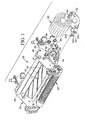
- Figure 1 illustrates a
reel unit 20 of the present invention that is intended to be pulled or pushed by a tractor or other vehicle. Typical known vehicles and cutting reel units are disclosed for example in U.S. Patents 5,343,680; 5,412,931 and 5,459,984. - The
reel unit 20 illustrated includes asupport frame 24 that includessideplate sideplate rear rollers sideplates blades 44, is rotatably carried by the two housings 38. Thereel 42, when rotated, can cut grass between theblades 44 and a bedknife (not shown) as is known. The housing 38 include bearings (not shown) that journal ends of acenter shaft 48 of thereel 42. Amotor assembly 50 is mounted to one of the housing 38. Theassembly 50 includes amounting flange 52 that carries twostuds 54. Thestuds 54 each have a threadedshaft 54a, ahead 54b, and anut 54c. Theshaft 54a passes loosely through a hole in theflange 52. - The housing 38 includes an
annular mating surface 62 and two spaced-apart slots slots 64 is open in a downward direction and theother slot 66 is open in an upward direction. - To install the
motor assembly 50 to the housing 38, theassembly 50 is placed onto themating surface 62 with onestud shaft 54a located near to but below theslot 64 and theother stud shaft 54a is located near to but above theslot 66. Theassembly 50 is then rotated about a horizontal axis to seat thestud shafts 54a into therespective slots flange 52 together. - According to this aspect of the invention, the
assembly 50 can be removed and reinstalled without ever having to separate the nuts 54c from theirrespective shafts 54a. The disassembly and re-assembly is more quickly accomplished without the need to completely unscrew the nuts 54c and withdraw thestuds 54. Although the preferred embodiment illustratesstuds 54 withheads 54b and nuts 54c, it is encompassed by the invention that theheads 54b can be replaced by nuts or that the nuts 54c can be replaced by tapped holes in theflange 52. - Figures 2-5 illustrate the
motor assembly 50 in more detail. Theassembly 50 includes a brush-less,permanent magnet motor 70 driven by a supply of electric power conducted throughwires 74. Thewires 74 penetrate amotor housing 76. Themotor housing 76 includes a circumferentially arranged, longitudinally extending, heat-dissipatingfins 82 on a rear face thereof, and longitudinally extending, radially extending, heat-dissipatingfins 82 on the circumference thereof. - According to the preferred embodiment of the invention, for a 22" long, 5" diameter reel, a motor having a power rating of 1 KW is used. The motor is rated at 860 watts continuous and 1200 watts at 50% duty cycle at 30 amps input. The motor is preferably of the type described in U.S. serial No.10/651,015, filed on the same day as the present application, and identified by attorney docket No. 6270P0350US. The motor is powered by an alternator driven into rotation by the mowing vehicle engine, such as described in U.S. patent 6,531,850. This motor and reel configuration is advantageous for cutting short grass areas, such as golf course putting greens.
- Other permanent magnet motors are disclosed for example in U.S. Patents: 4,242,610; 5,758,709; 6,555,941; 6,353,275 and 6,087,752, herein incorporated by reference.
- The
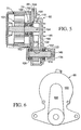
motor 70 is fastened to acasing 80 byfasteners 84, which can be cap screws and nuts. Thecasing 80 includes afront cover 86 and arear cover 88. Theflange 52 can be a unitary portion of thefront cover 86. Thefront cover 86 is fastened to therear cover 88 by thefasteners 84, which clamp themotor housing 76, therear cover 88 and thefront cover 86 together, and byscrews 90, threaded into threadedholes 92 of thefront cover 86. - As illustrated in Figure 5, the motor includes a
rotor 102 that drives amotor output shaft 104. Theoutput shaft 104 passes through a bearingassembly 108 held in place by themotor housing 76. Theshaft 104 is keyed to a firsttoothed pulley 110 within thecasing 80. Asecondary output shaft 116 is located below thepulley 110. Theshaft 116 is journaled by arear bearing 120 carried in a concave portion 118 of therear cover 88, and afront bearing 122 carried by thefront cover 86. Theshaft 116 is keyed to a secondtoothed pulley 128. A toothed belt 132 wraps around the pulleys 110,128. - The
shaft 116 extends forwardly through a hole in thefront cover 86 to a free end thereof, where it is engaged to ashaft coupling 138. Theshaft coupling 138 includes asplined hole 140 which receives a splined end of thereel shaft 48 when theassembly 50 is installed onto the housing 38. Thefront cover 86 also includes anannular mating surface 142 that presses against theannular surface 62 of the housing 38 when theassembly 50 is completely installed. - The pulleys 110,128 are relatively sized so as to rotate the
reel 42 at the desired speed and torque given the output of themotor 70. According to the preferred embodiment of the invention, a turn ratio between the motor output shaft and the secondary output shaft is 1.28 to 1. - Figure 4 illustrates the
motor 70 separated from thecasing 80. Themotor housing 76 includes afront surface 152 with a raisedjournal 154 for holding the bearingassembly 108. Therear cover 88 has a correspondingly shaped, coextensive rear surface 162 (Figure 5) that fits flushly against thefront surface 152 so as to maximize heat transfer surface area and rate from themotor housing 76 to therear cover 88. Thefront cover 86 has a large rear surface 166 (Figure 6) which fits flushly against a largefront surface 168 of the rear cover, thefront surface 168 substantially correspondingly shaped and coextensive with therear surface 162 of therear cover 88, to maximize heat transfer surface area and rate between therear cover 88 and afront cover 86. - The front cover includes laterally and longitudinally extending, heat-dissipating
plate fins 172 to enhance heat transfer from themotor housing 76 via therear cover 88 and thefront cover 86. - Figure 6 illustrates the inside surface of the
front cover 86. - In a region of the motor attachment, the large, horseshoeshaped
flat surface 166 is pressed against thecorresponding surface 168 of therear cover 88. Thefront cover 86 includes aconcave portion 188 which provides a volume within thecasing 80 for the operation of thepulleys - From the foregoing, it will be observed that numerous variations and modifications may be effected without departing from the spirit and scope of the invention. It is to be understood that no limitation with respect to the specific apparatus illustrated herein is intended or should be inferred. It is, of course, intended to cover by the appended claims all such modifications as fall within the scope of the claims.
Claims (10)
- Electric motor drive for a reel mower, comprising a motor (70), preferably a brush-less permanent magnet electric motor, having a rotor (102), a stator, and a motor housing (76) that carries said rotor (102) and stator, said rotor (102) having a rotor output shaft (104) extending from said housing(76); a casing (80) mounted to said motor housing (76); an endless traction member, preferably comprising a belt (132), engaged to said rotor output shaft (104) to be circulated by rotation of said rotor output shaft (104); a secondary output shaft (116) engaged by said endless traction member to be rotated by circulation of said endless traction member, said secondary output shaft (116) extending from inside said casing (80) to outside said casing (80) to be operatively connected to an external device, preferably a reel (42), to rotate said external device.
- The drive according to claim 1, wherein said motor housing (76) and said casing (80) both include heat-dissipating fins (82, 172).
- The drive according to claim 1 or 2, wherein said motor housing (76) comprises radially and axially extending, heat-dissipating plate fins (82) and said casing (80) comprises horizontal, axially extending heat-dissipating plate fins (172).
- The drive according to one or several of the previous claims, wherein said casing (80) comprises laterally extending flanges (52), said flanges (52) sized and arranged to receive a fastener (84) on each side of the secondary output shaft (116) to fasten said casing to an external frame (24).
- The drive according to one or several of the previous claims, wherein said casing (80) comprises a front cover (86) and a rear cover (88), said front cover (86) comprises heat fins (82) and said rear cover (88) comprises a bearing (120) for said secondary output shaft (116), said front and rear covers (86, 88) fastened to each other and to said motor housing (76).
- Drive according to one or several of the previous claims, wherein said front cover (86) comprises a front bearing (122) for said secondary output shaft (116).
- Reel mower, comprising a reel (42) having a plurality of blades (44) arranged around a lateral axis, a frame having side members (26, 28) which support said reel (42) and allow rotation of said reel (42) about said lateral axis, comprising a drive according to one or several of the previous claims, whereby the casing (80) is mounted to said frame (24) and the shaft (104) is connected to an end of said reel (42).
- Reel mower according to claim 7, wherein said casing (80) is mounted to said frame (24) by at least one threaded member (54) engaged into a slot (64, 66), wherein loosening of said threaded member (54) permits withdrawal of said threaded member (54) from said slot (64, 66) in a direction substantially perpendicular to an axial direction of said threaded member (54).
- Reel mower according to claim 7 or 8, wherein said casing (80) is arranged to support said rotor output shaft (104) vertically above said secondary output shaft (116), an axis of said rotor (102) located above said lateral axis of said reel (42).
- Reel mower according to one or several of the claims 7 to 9, wherein said casing (80) is mounted to said frame (24) by two threaded studs (54), each stud (54) engaged on one end to said casing (80) and on an opposite end by a head or nut (54c), said frame (24) including open slots corresponding in position to said studs (54), wherein said studs (54) can be positioned into said slots (64, 66) by a positioning of said studs (54) adjacent said corresponding slots (64, 66) and then a turning of said casing (80) about an axis of said reel (42) to slide said studs (54) into said slots (64, 66), and thereafter said heads or said nuts (54c) can be tightened against said frame (24) on a side of said frame (24) opposite said casing to secure said casing (80) to said frame (24).
Applications Claiming Priority (2)
| Application Number | Priority Date | Filing Date | Title |
|---|---|---|---|
| US651016 | 2003-08-26 | ||
| US10/651,016 US6946762B2 (en) | 2003-08-26 | 2003-08-26 | Electric motor drive for a reel mower |
Publications (2)
| Publication Number | Publication Date |
|---|---|
| EP1510121A1 true EP1510121A1 (en) | 2005-03-02 |
| EP1510121B1 EP1510121B1 (en) | 2007-04-25 |
Family
ID=34104721
Family Applications (1)
| Application Number | Title | Priority Date | Filing Date |
|---|---|---|---|
| EP04103998A Expired - Fee Related EP1510121B1 (en) | 2003-08-26 | 2004-08-20 | Electric motor drive for reel mower |
Country Status (3)
| Country | Link |
|---|---|
| US (1) | US6946762B2 (en) |
| EP (1) | EP1510121B1 (en) |
| DE (1) | DE602004006058T2 (en) |
Cited By (1)
| Publication number | Priority date | Publication date | Assignee | Title |
|---|---|---|---|---|
| WO2007121759A1 (en) * | 2006-04-20 | 2007-11-01 | Danfoss Bauer Gmbh | Motor unit |
Families Citing this family (18)
| Publication number | Priority date | Publication date | Assignee | Title |
|---|---|---|---|---|
| JP2006056354A (en) * | 2004-08-19 | 2006-03-02 | Honda Motor Co Ltd | High-voltage wiring protecting structure of electrically propelled vehicle |
| US20080289309A1 (en) * | 2005-02-09 | 2008-11-27 | Gust Jackie R | Mower with Hybrid Prime Mover Having Fuel Cell, Brushless Electric Motors for Driving Cutting Units, and Electric/Hydraulic Actuator for Lift and Lower System |
| WO2007038857A1 (en) * | 2005-10-03 | 2007-04-12 | Jeff Buchko | Magnetic connection of driving and driven connection for a reel mower |
| US7728534B2 (en) | 2006-10-17 | 2010-06-01 | Mtd Products Inc | Hybrid electric lawnmower |
| WO2008048615A2 (en) | 2006-10-17 | 2008-04-24 | Desa Ip, Llc | Hybrid electric device |
| US8732896B2 (en) | 2006-10-17 | 2014-05-27 | Mtd Products Inc | Hybrid electric cleaning device |
| US20080196371A1 (en) * | 2007-02-20 | 2008-08-21 | Textron Inc. | Electrically Driven, Reel-Mower Accessories |
| US8076873B1 (en) | 2007-06-01 | 2011-12-13 | Mtd Products Inc | Hybrid outdoor power equipment |
| US8738237B2 (en) | 2008-02-28 | 2014-05-27 | Deere & Company | Control system for starting electrically powered implements |
| US7647757B2 (en) * | 2008-04-07 | 2010-01-19 | Deere & Company | Auxiliary drive shaft connection on reel mower cutting unit |
| US7930872B2 (en) * | 2008-11-12 | 2011-04-26 | Alamo Group, Inc. | Drive system for a flail mower |
| US8227948B1 (en) * | 2009-01-09 | 2012-07-24 | Hydro-Gear Limited Partnership | Electric motor |
| US8099936B2 (en) * | 2009-01-27 | 2012-01-24 | Textron Innovations Inc. | Electrically powered flail mower |
| CN103107665A (en) * | 2011-11-11 | 2013-05-15 | 德昌电机(深圳)有限公司 | Permanent magnet motor and electric tool and mower utilizing the same |
| US20140215986A1 (en) * | 2013-02-06 | 2014-08-07 | Textron Inc. | Induction Reel Motor |
| US9204595B2 (en) * | 2014-01-29 | 2015-12-08 | Textron Inc. | Quick connect system for attaching motors to cylinder mowers |
| US9693501B2 (en) | 2014-08-06 | 2017-07-04 | Shivvers Group Incorporated | Mower with scissor lift mowing height adjustment mechanism |
| KR102517619B1 (en) * | 2020-08-13 | 2023-04-03 | 최지훈 | Device for power transmission |
Citations (12)
| Publication number | Priority date | Publication date | Assignee | Title |
|---|---|---|---|---|
| GB907245A (en) * | 1958-02-06 | 1962-10-03 | Zahnradfabrik Friedrichshafen | Improvements in and relating to change-speed planetary gearing |
| US3267594A (en) * | 1963-06-05 | 1966-08-23 | Sunbeam Corp | Apparatus for removing snow |
| US4242610A (en) | 1978-12-26 | 1980-12-30 | The Garrett Corporation | Wedge-shaped permanent magnet rotor assembly |
| US4995227A (en) * | 1989-10-25 | 1991-02-26 | Foster Harry C | Power assisted reel type lawn mower |
| US5343680A (en) | 1992-09-03 | 1994-09-06 | Deere & Company | Suspension mechanism for reel mowers |
| US5412931A (en) | 1993-08-12 | 1995-05-09 | Deere & Company | Slidable grass catcher |
| US5758709A (en) | 1995-12-04 | 1998-06-02 | General Electric Company | Method of fabricating a rotor for an electric motor |
| US5896734A (en) * | 1997-09-02 | 1999-04-27 | Textron Inc. | Rotation drive connection for a reel mower |
| US6353275B1 (en) | 1997-10-13 | 2002-03-05 | Noriyoshi Nishiyama | Rotor with adhesive filled grooves fastening interior permanent magnets |
| US6531850B1 (en) | 2001-08-20 | 2003-03-11 | Deere & Company | Load controller utilizing alternator field excitation |
| US20030067228A1 (en) * | 2001-10-09 | 2003-04-10 | Vanjani Chandu R. | Heat dissipative brushless electric motor assembly |
| US6555941B1 (en) | 2002-03-08 | 2003-04-29 | Dura-Trac Motors, Inc. | Brushless permanent magnet motor or alternator with variable axial rotor/stator alignment to increase speed capability |
Family Cites Families (21)
| Publication number | Priority date | Publication date | Assignee | Title |
|---|---|---|---|---|
| US2734328A (en) * | 1956-02-14 | Lawn mower | ||
| US2057417A (en) * | 1931-07-18 | 1936-10-13 | Toro Mfg Company | Gang lawn mower |
| US2881887A (en) * | 1954-04-19 | 1959-04-14 | Louis D Faas | Clutch for power mower |
| US2923117A (en) * | 1957-05-20 | 1960-02-02 | Scott W Henderson | Rotary cutter |
| US3732673A (en) * | 1971-07-27 | 1973-05-15 | L Winn | Motor drive for a lawn mower |
| US4021996A (en) * | 1976-02-26 | 1977-05-10 | Bartlett Gordon E | Golf greens mower |
| US4306402A (en) * | 1978-05-24 | 1981-12-22 | Ahi Whimpway Limited | Gang mowers |
| US4546601A (en) * | 1983-02-11 | 1985-10-15 | Skovhoj Jens B | Lawn and garden maintenance apparatus |
| US4680922A (en) * | 1983-09-20 | 1987-07-21 | Brouwer Turf Equipment Limited | Mower |
| US4685280A (en) * | 1983-10-26 | 1987-08-11 | Lloyd Lawrence L | Mower cutting unit |
| GB8905759D0 (en) * | 1989-03-13 | 1989-04-26 | Ransomes Sims & Jefferies Plc | Grass cutting unit |
| US5261213A (en) * | 1992-08-06 | 1993-11-16 | Humphrey John L | Greensroller |
| US5293729A (en) * | 1992-10-07 | 1994-03-15 | Deere & Company | Pivot mechanism for reel mower cutting units |
| US5406778A (en) * | 1994-02-03 | 1995-04-18 | Ransomes America Corporation | Electric drive riding greens mower |
| US6082084A (en) * | 1995-11-13 | 2000-07-04 | Ransomes America Corporation | Electric riding mower with electric steering system |
| US5934053A (en) * | 1996-11-01 | 1999-08-10 | Fillman; Alan R. | Removable battery tray system for an electrically powered mower |
| US5934051A (en) * | 1997-02-06 | 1999-08-10 | Textron, Inc. | Solid state mow system for electrically powered mower |
| US6082082A (en) * | 1997-02-14 | 2000-07-04 | Textron Inc. | Dual motor drive system for electrically powered mower |
| US6430902B1 (en) * | 1997-12-09 | 2002-08-13 | Textron, Inc. | Mower cutting unit having an internal motor |
| ES2283422T3 (en) * | 2000-06-26 | 2007-11-01 | The Toro Company | CYLINDER MANUAL CYLINDER. |
| US6794779B2 (en) * | 2001-12-17 | 2004-09-21 | Young & Franklin Inc. | Compact electromechanical linear actuator |
-
2003
- 2003-08-26 US US10/651,016 patent/US6946762B2/en not_active Expired - Lifetime
-
2004
- 2004-08-20 DE DE602004006058T patent/DE602004006058T2/en active Active
- 2004-08-20 EP EP04103998A patent/EP1510121B1/en not_active Expired - Fee Related
Patent Citations (13)
| Publication number | Priority date | Publication date | Assignee | Title |
|---|---|---|---|---|
| GB907245A (en) * | 1958-02-06 | 1962-10-03 | Zahnradfabrik Friedrichshafen | Improvements in and relating to change-speed planetary gearing |
| US3267594A (en) * | 1963-06-05 | 1966-08-23 | Sunbeam Corp | Apparatus for removing snow |
| US4242610A (en) | 1978-12-26 | 1980-12-30 | The Garrett Corporation | Wedge-shaped permanent magnet rotor assembly |
| US4995227A (en) * | 1989-10-25 | 1991-02-26 | Foster Harry C | Power assisted reel type lawn mower |
| US5459984A (en) | 1992-09-03 | 1995-10-24 | Deere & Company | Suspension mechanism for reel mowers |
| US5343680A (en) | 1992-09-03 | 1994-09-06 | Deere & Company | Suspension mechanism for reel mowers |
| US5412931A (en) | 1993-08-12 | 1995-05-09 | Deere & Company | Slidable grass catcher |
| US5758709A (en) | 1995-12-04 | 1998-06-02 | General Electric Company | Method of fabricating a rotor for an electric motor |
| US5896734A (en) * | 1997-09-02 | 1999-04-27 | Textron Inc. | Rotation drive connection for a reel mower |
| US6353275B1 (en) | 1997-10-13 | 2002-03-05 | Noriyoshi Nishiyama | Rotor with adhesive filled grooves fastening interior permanent magnets |
| US6531850B1 (en) | 2001-08-20 | 2003-03-11 | Deere & Company | Load controller utilizing alternator field excitation |
| US20030067228A1 (en) * | 2001-10-09 | 2003-04-10 | Vanjani Chandu R. | Heat dissipative brushless electric motor assembly |
| US6555941B1 (en) | 2002-03-08 | 2003-04-29 | Dura-Trac Motors, Inc. | Brushless permanent magnet motor or alternator with variable axial rotor/stator alignment to increase speed capability |
Cited By (1)
| Publication number | Priority date | Publication date | Assignee | Title |
|---|---|---|---|---|
| WO2007121759A1 (en) * | 2006-04-20 | 2007-11-01 | Danfoss Bauer Gmbh | Motor unit |
Also Published As
| Publication number | Publication date |
|---|---|
| US20050044838A1 (en) | 2005-03-03 |
| US6946762B2 (en) | 2005-09-20 |
| EP1510121B1 (en) | 2007-04-25 |
| DE602004006058T2 (en) | 2007-12-27 |
| DE602004006058D1 (en) | 2007-06-06 |
Similar Documents
| Publication | Publication Date | Title |
|---|---|---|
| US6946762B2 (en) | Electric motor drive for a reel mower | |
| US4203710A (en) | Unified pump and generator arrangement | |
| US7677017B2 (en) | Modular power source for walk-behind mower | |
| US4021690A (en) | Wheel borne counter rotating disc alternator | |
| RU2252477C2 (en) | Power generator assembly of drive engine and generator | |
| US10833560B1 (en) | Combination electric generator with electric clutch | |
| US7969051B2 (en) | Forced-fluid flow ventilating system for rotating electrical machines and rotating electrical machine comprising same | |
| JP2615185B2 (en) | AC generator for vehicles | |
| WO2004047255A2 (en) | Axial flux motor assembly | |
| US20100001488A1 (en) | Construction kit and method for converting a bicycle. and bicycle | |
| CA2083452C (en) | High torque and speed dc motors | |
| US7530214B1 (en) | Auxiliary drive mounted to reel mower cutting unit | |
| US6199391B1 (en) | Magnetic clutch method and apparatus for driving a vehicle air conditioner | |
| JP2017184606A (en) | Improved front flange of rotary electrical machine, and rotary electrical machine comprising flange of this type | |
| JPH0870554A (en) | Generator | |
| CN203301992U (en) | Grass trimmer with front motor | |
| US11895947B2 (en) | Mower with motor cooling arrangement | |
| DE102009011347A1 (en) | Drive unit for a fan and arrangement with a drive unit | |
| US6430902B1 (en) | Mower cutting unit having an internal motor | |
| US5914551A (en) | Electrical alternator | |
| US7264069B2 (en) | Vehicle or lawn and garden maintenance equipment having a generator, and power takeoff assembly for a vehicle or lawn and garden maintenance equipment | |
| EP2751910B1 (en) | Electric machine with improved cooling | |
| CA2150531A1 (en) | Electricity driven device and method for increasing the rotational inertia of a rotary object or the blade of a lawn mower | |
| US20070051427A1 (en) | Cooled clutch assembly and stump grinder incorporating the same | |
| AU756482B2 (en) | Magnetic clutch method and apparatus for driving a vehicle air conditioner |
Legal Events
| Date | Code | Title | Description |
|---|---|---|---|
| PUAI | Public reference made under article 153(3) epc to a published international application that has entered the european phase |
Free format text: ORIGINAL CODE: 0009012 |
|
| AK | Designated contracting states |
Kind code of ref document: A1 Designated state(s): AT BE BG CH CY CZ DE DK EE ES FI FR GB GR HU IE IT LI LU MC NL PL PT RO SE SI SK TR |
|
| AX | Request for extension of the european patent |
Extension state: AL HR LT LV MK |
|
| 17P | Request for examination filed |
Effective date: 20050902 |
|
| AKX | Designation fees paid |
Designated state(s): DE GB |
|
| GRAP | Despatch of communication of intention to grant a patent |
Free format text: ORIGINAL CODE: EPIDOSNIGR1 |
|
| GRAS | Grant fee paid |
Free format text: ORIGINAL CODE: EPIDOSNIGR3 |
|
| GRAA | (expected) grant |
Free format text: ORIGINAL CODE: 0009210 |
|
| AK | Designated contracting states |
Kind code of ref document: B1 Designated state(s): DE GB |
|
| REG | Reference to a national code |
Ref country code: GB Ref legal event code: FG4D |
|
| REF | Corresponds to: |
Ref document number: 602004006058 Country of ref document: DE Date of ref document: 20070606 Kind code of ref document: P |
|
| PLBE | No opposition filed within time limit |
Free format text: ORIGINAL CODE: 0009261 |
|
| STAA | Information on the status of an ep patent application or granted ep patent |
Free format text: STATUS: NO OPPOSITION FILED WITHIN TIME LIMIT |
|
| 26N | No opposition filed |
Effective date: 20080128 |
|
| PGFP | Annual fee paid to national office [announced via postgrant information from national office to epo] |
Ref country code: DE Payment date: 20170719 Year of fee payment: 14 |
|
| REG | Reference to a national code |
Ref country code: DE Ref legal event code: R119 Ref document number: 602004006058 Country of ref document: DE |
|
| PG25 | Lapsed in a contracting state [announced via postgrant information from national office to epo] |
Ref country code: DE Free format text: LAPSE BECAUSE OF NON-PAYMENT OF DUE FEES Effective date: 20190301 |
|
| PGFP | Annual fee paid to national office [announced via postgrant information from national office to epo] |
Ref country code: GB Payment date: 20210827 Year of fee payment: 18 |
|
| GBPC | Gb: european patent ceased through non-payment of renewal fee |
Effective date: 20220820 |
|
| PG25 | Lapsed in a contracting state [announced via postgrant information from national office to epo] |
Ref country code: GB Free format text: LAPSE BECAUSE OF NON-PAYMENT OF DUE FEES Effective date: 20220820 |