EP1510123A1 - Method and device for controlling a height-adjustable cutting device - Google Patents
Method and device for controlling a height-adjustable cutting device Download PDFInfo
- Publication number
- EP1510123A1 EP1510123A1 EP04018797A EP04018797A EP1510123A1 EP 1510123 A1 EP1510123 A1 EP 1510123A1 EP 04018797 A EP04018797 A EP 04018797A EP 04018797 A EP04018797 A EP 04018797A EP 1510123 A1 EP1510123 A1 EP 1510123A1
- Authority
- EP
- European Patent Office
- Prior art keywords
- reel
- height
- torque
- sensor
- drive system
- Prior art date
- Legal status (The legal status is an assumption and is not a legal conclusion. Google has not performed a legal analysis and makes no representation as to the accuracy of the status listed.)
- Granted
Links
- 238000005520 cutting process Methods 0.000 title claims abstract description 31
- 238000000034 method Methods 0.000 title claims abstract description 15
- 230000001419 dependent effect Effects 0.000 claims abstract description 9
- 238000003306 harvesting Methods 0.000 claims description 6
- 230000006870 function Effects 0.000 claims description 2
- 230000001105 regulatory effect Effects 0.000 description 3
- 241001124569 Lycaenidae Species 0.000 description 2
- 230000001276 controlling effect Effects 0.000 description 2
- 238000013500 data storage Methods 0.000 description 2
- 230000000694 effects Effects 0.000 description 2
- 239000000463 material Substances 0.000 description 2
- 206010020751 Hypersensitivity Diseases 0.000 description 1
- 208000026935 allergic disease Diseases 0.000 description 1
- 230000005611 electricity Effects 0.000 description 1
- 230000009610 hypersensitivity Effects 0.000 description 1
- 238000004519 manufacturing process Methods 0.000 description 1
- 230000002093 peripheral effect Effects 0.000 description 1
- 239000007787 solid Substances 0.000 description 1
Images

Classifications
-
- A—HUMAN NECESSITIES
- A01—AGRICULTURE; FORESTRY; ANIMAL HUSBANDRY; HUNTING; TRAPPING; FISHING
- A01D—HARVESTING; MOWING
- A01D41/00—Combines, i.e. harvesters or mowers combined with threshing devices
- A01D41/12—Details of combines
- A01D41/14—Mowing tables
- A01D41/141—Automatic header control
-
- A—HUMAN NECESSITIES
- A01—AGRICULTURE; FORESTRY; ANIMAL HUSBANDRY; HUNTING; TRAPPING; FISHING
- A01D—HARVESTING; MOWING
- A01D57/00—Delivering mechanisms for harvesters or mowers
- A01D57/01—Devices for leading crops to the mowing apparatus
- A01D57/02—Devices for leading crops to the mowing apparatus using reels
- A01D57/04—Arrangements for changing the position of the reels
Definitions
- the invention relates to a device and a method for controlling a height adjustable cutting unit of a combine harvester according to the generic terms of the Claims 1 and 11.
- Mobile Emtemaschinen are with a height-adjustable cutting provided, which the crop from the field cuts and then picks up.
- the crop is using a knife bar cut off and with a auger a subsequent Threshing supplied.
- the cutting unit carries a reel, which is the assumption of the crop to the cutter bar and the further promotion to the auger ensures that a continuous crop flow and the threshing device is fed continuously.
- the function of the reel is with lying crop particularly important. The reel tines on the reel lift this Crop so that the knife bar gets under the crop to the stalks close to the ground, so that the loss of crop is as low as possible.
- the peripheral speed of the reel is so set that an advance to the forward speed of the combine given is.
- the height of the reel is z. B. as low as possible for stored grain adjusted for the best possible effect. Because the crop is in the field However, in height and density varies, the height of the reel must be constant be adjusted. This also applies if the operator has a different cutting height of the Cutting table adjusts.
- combine harvesters are on the market, where several heights of the reel, one cutting height of the cutting unit, a reel speed and a harvest condition is assigned.
- the assignments are stored in a data storage unit, with the height of the reel in the ongoing operation is changed and saved again.
- EP 0 377 163 A1 is a self-propelled harvester with one of a Drive motor rotating driven reel known.
- the reel speed is in Dependent on the priority speed of the combine.
- the height The reel is chosen so that the crop on the one hand not claimed unnecessarily On the other hand, however, a continuous crop flow is ensured, the Height of the reel is determined by the operator.
- a disadvantage of these known combines is that the operator the height of the Manually constantly changing and rewinding reel to get the best possible effect to achieve the reel.
- the attitude of the height is thereby from the experience of the Operator dependent.
- the height is a solid empirical value from the operator given that the current, constantly changing crop parameters are not considered.
- the present invention is therefore the object of a combine harvester in such a way that the operator of the adjustment of the optimum height the reel is relieved.
- the reel height can be adjusted depending on the load, the reel height can be adjusted in Depending on the force acting on the crop from the reel force regulated become. This has the advantage that the reel always in the same way on the Crop material acts.
- the tensile force is advantageously defined by the reel torque to the Sum of all pulling forces acting along the reel at the same time.
- the operator inputs a maximum tensile force via a control panel and the maximum pulling force is stored in a data memory of the control unit.
- the operator sets the control range once at the beginning of the harvest journey Experience values, and the default value is always for the automatic regulation of reel height available.
- the reel height is advantageously adjusted only when the determined Coil torque around thresholds and / or a specific period of time deviates from the maximum permitted reel torque.
- the Operator does not specify any further value, which further relieves the driver means.
- the setpoint curves are advantageously in the data memory of the control unit stored so that they are available at any time for regulating the reel height.
- the inventive device for Control of the reel advantageously comprises a sensor for detecting the Reel traction and a rotation angle sensor for detecting the reel height, wherein the rotation angle sensor and the sensor for detecting the reel traction on a Control unit coupled, and the reel height with the control unit load-dependent is adjustable.
- the device can be carried out without great structural complexity be because the electronic components used in a simple way to the existing mechanical components can be connected.
- the sensor may for example be designed as a pressure sensor and the Rotary drive system, for example, be a hydraulic rotary drive system, wherein the pressure sensor is disposed in the hydraulic rotary drive system and generates a pressure that varies depending on the reel torque.
- the senor is electrical Electricity meter running and the rotary drive system is an electric Rotary drive system, wherein the ammeter in the. electrical Rotary drive system is arranged and measures a current that depends on Reel torque changes.
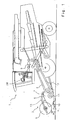
- a combine harvester 1 is shown in side view, at the vertical pivotable feed shaft 2 a cutting unit 3 is arranged. With the pivotable feed shaft 2, the cutting unit 3 to a desired Cutting height L adjustable.
- the cutting unit 3 consists of a cutting table 4, and from an on two herebyverschwenkbaren reel support arms 5 on the cutting table 4 attached reel 6. Between the cutting table 4 and the reel support arms 5 are hinged two hydraulic cylinders 13, with which the reel support arms 5 to a Pivot point 14 rotating, and be pivoted while the height of the reel 6 change. In addition, between the reel support arms 5 and the reel 6 two further hydraulic cylinder 17 is attached, with which the position of the reel in horizontal direction in relation to the cutting table 4 is set.
- the driven with a motor 7 reel 6 provides first for a continuous acceptance of the harvested crop and for its consistent production through the cutting unit 3 and the feed shaft 2 to a known and therefore not explained in detail here threshing device 9 of the combine 1.
- Das Crop material is attached to a at the front edge of the cutting table 4 Knife bar 10 cut and then cut the crop with Help the reel 6 to a arranged in the cutting table 3, rotatably driven Feed auger 11 promoted.
- the auger 11 leads the crop to the Feed shaft 2 too.
- the feed chute 2 runs an inclined conveyor 12, the Crop to the threshing 9 promotes.
- FIG. 2 shows a section of the cutting unit 3 of the combine harvester 1 according to FIG. 1 including the there arranged sensors 19, 20, one with a data memory 24 equipped control unit 27 and a control panel 28.
- the current reel height H of the reel 6 is a in the hinge point 14th attached angle of rotation sensor 21 is measured, the angle of rotation ⁇ of the Coiler arms 5 measures.
- the signal HHS generated by the rotation angle sensor 21 is directly proportional to the reel height H.
- the motor 7 is a hydraulic motor 8, which is provided by a hydraulic drive system 29 is driven.
- a pressure sensor 22nd installed, with which a hydraulic pressure is generated, which depends on the Reel torque M changes.
- the signal HDS generated by the pressure sensor 22 is proportional to a load acting on the reel 6.
- the burden of Reel 6 is determined by determining the force acting on the reel 6 traction FH determined by the reel torque M.
- the signals HHS and HDS are the with the rotation angle sensor 21 and the Pressure sensor 22 connected control unit 27 supplied.
- a control panel 28 is also connected via the the driver specifies a maximum traction FM in the control unit 27 in a maximum permissible reel torque is converted.
- the control unit 27 calculates with the maximum permissible reel torque an upper threshold and a lower threshold and a lower one permissible reel torque.
- the control unit 27 evaluates the sensors 19, 20 provided Signals HHS and HDS off. For this purpose, the control unit calculates the deviation between the maximum permitted reel torque and the reel torque M. Depending on the calculated by the control unit 27 deviation of the Reel torque M to the maximum permitted reel torque is then one corresponding control command HHB to the hydraulic lifting drive system 15th given, which is connected to the hydraulic cylinder 13 and the Hydraulic cylinder 13 in accordance with the control command HHB on or extends to the Lowering or raising reel height H.
- the reel 6 is adjusted with the hydraulic lifting drive system 15 upwards, if the measured reel torque M is the maximum allowable Coiler torque exceeds for a certain period of time and down adjusted when the measured reel torque M the lower permissible Reel torque for a certain period of time.
- a preferred embodiment are for controlling the maximum allowable Reel torque in the data memory 24 of the control unit 27 setpoint curves 25 for a reel height H, which determines the height of the reel 6 in dependence on maximum reel torque, reel speed, speed of combine 1, cutting height, type of grain and more Determines harvest conditions.
- the motor 7 for the rotation of the reel 6 may also be an electric motor 9, the of an electric rotary drive system 30 is driven.
- an ammeter 23 is arranged, which is a current measures, which changes depending on the reel torque M.
Abstract
Description
Die Erfindung betrifft eine Vorrichtung und ein Verfahren zur Steuerung eines
höhenverstellbaren Schneidwerks eines Mähdreschers nach den Oberbegriffen der
Ansprüche 1 und 11.The invention relates to a device and a method for controlling a
height adjustable cutting unit of a combine harvester according to the generic terms of the
Fahrbare Emtemaschinen, insbesondere Mähdrescher, sind mit einem höhenverstellbaren Schneidwerk versehen, welches das Erntegut vom Feld schneidet und dann aufnimmt. Das Erntegut wird mit einem Messerbalken abgeschnitten und mit einer Einzugsschnecke einer nachfolgenden Drescheinrichtung zugeführt. Das Schneidwerk trägt eine Haspel, die die Annahme des Erntegutes zum Messerbalken und die Weiterförderung zur Einzugsschnecke sicherstellt, so dass ein kontinuierlicher Gutfluss entsteht und die Drescheinrichtung kontinuierlich beschickt wird. Die Funktion der Haspel ist bei liegendem Erntegut besonders wichtig. Die an der Haspel angeordneten Haspelzinken heben das Erntegut an, damit der Messerbalken unter das Erntegut gelangt, um die Halme bodennah abzuschneiden, so dass der Ernteverlust so gering wie möglich ist. Um eine gute Förderleistung zu erreichen, ist die Umfangsgeschwindigkeit der Haspel so eingestellt, dass eine Voreilung zur Vorfahrtgeschwindigkeit des Mähdreschers gegeben ist. Die Höhe der Haspel wird z. B. bei Lagergetreide möglichst niedrig eingestellt, um eine bestmögliche Wirkung zu erzielen. Da das Erntegut auf dem Feld jedoch in der Höhe und der Dichte variiert, muss die Höhe der Haspel ständig angepasst werden. Dies gilt auch, wenn der Bediener eine andere Schnitthöhe des Schneidwerks einstellt.Mobile Emtemaschinen, especially combine harvesters, are with a height-adjustable cutting provided, which the crop from the field cuts and then picks up. The crop is using a knife bar cut off and with a auger a subsequent Threshing supplied. The cutting unit carries a reel, which is the assumption of the crop to the cutter bar and the further promotion to the auger ensures that a continuous crop flow and the threshing device is fed continuously. The function of the reel is with lying crop particularly important. The reel tines on the reel lift this Crop so that the knife bar gets under the crop to the stalks close to the ground, so that the loss of crop is as low as possible. Around To achieve a good flow rate, the peripheral speed of the reel is so set that an advance to the forward speed of the combine given is. The height of the reel is z. B. as low as possible for stored grain adjusted for the best possible effect. Because the crop is in the field However, in height and density varies, the height of the reel must be constant be adjusted. This also applies if the operator has a different cutting height of the Cutting table adjusts.
Um den Bediener während der Fahrt zu entlasten, sind Mähdrescher auf dem Markt, bei denen mehreren Höhen der Haspel, jeweils eine Schnitthöhe des Schneidwerks, eine Haspeldrehzahl und eine Erntebedingung zugeordnet wird. Die Zuordnungen werden in einer Datenspeichereinheit gespeichert, wobei die Höhe der Haspel im laufenden Betrieb verändert und neu gespeichert wird.To relieve the operator while driving, combine harvesters are on the market, where several heights of the reel, one cutting height of the cutting unit, a reel speed and a harvest condition is assigned. The assignments are stored in a data storage unit, with the height of the reel in the ongoing operation is changed and saved again.
Aus der EP 0 377 163 A1 ist eine selbstfahrende Erntemaschine mit einer von einem Antriebsmotor rotierend angetriebenen Haspel bekannt. Die Haspeldrehzahl wird in Abhängigkeit von der Vorfahrtgeschwindigkeit des Mähdreschers geregelt. Die Höhe der Haspel ist so gewählt, dass das Erntegut einerseits nicht unnötig beansprucht wird, andererseits jedoch ein kontinuierlicher Gutfluss gewährleistet ist, wobei die Höhe der Haspel vom Bediener festgelegt wird.From EP 0 377 163 A1 is a self-propelled harvester with one of a Drive motor rotating driven reel known. The reel speed is in Dependent on the priority speed of the combine. The height The reel is chosen so that the crop on the one hand not claimed unnecessarily On the other hand, however, a continuous crop flow is ensured, the Height of the reel is determined by the operator.
Nachteilig bei diesen bekannten Mähdreschern ist, dass der Bediener die Höhe der Haspel ständig manuell ändern und speichern muss, um die bestmögliche Wirkung der Haspel zu erzielen. Die Einstellung der Höhe ist dabei von der Erfahrung des Bedieners abhängig. Die Höhe wird als fester Erfahrungswert vom Bediener vorgegeben, der die momentanen, sich ständig ändernden Ernteparameter nicht berücksichtigt.A disadvantage of these known combines is that the operator the height of the Manually constantly changing and rewinding reel to get the best possible effect to achieve the reel. The attitude of the height is thereby from the experience of the Operator dependent. The height is a solid empirical value from the operator given that the current, constantly changing crop parameters are not considered.
Der vorliegenden Erfindung liegt daher die Aufgabe zugrunde einen Mähdrescher derart weiterzuentwickeln, dass der Bediener von der Einstellung der optimalen Höhe der Haspel entlastet wird.The present invention is therefore the object of a combine harvester in such a way that the operator of the adjustment of the optimum height the reel is relieved.
Diese Aufgabe wird erfindungsgemäß durch die kennzeichnenden Merkmale der
Ansprüche 1 und 11 gelöst. Weitere vorteilhafte Ausführungen des
Erfindungsgegenstandes ergeben sich aus den nachgeordneten Ansprüchen.This object is achieved by the characterizing features of
Indem die Haspelhöhe lastabhängig verstellbar ist, kann die Haspelhöhe in Abhängigkeit von der von der Haspel auf das Erntegut wirkenden Kraft geregelt werden. Dies hat den Vorteil, dass die Haspel stets in gleicher Weise auf das Erntegut einwirkt.Since the reel height can be adjusted depending on the load, the reel height can be adjusted in Depending on the force acting on the crop from the reel force regulated become. This has the advantage that the reel always in the same way on the Crop material acts.
Indem die Belastung durch die Ermittlung der auf die Haspel wirkenden Zugkraft bestimmt wird, kann im Umkehrschluss die auf das Erntegut ausgeübte Kraft bestimmt werden, da beide Kräfte gleich groß sind und im Gleichgewicht stehen. Dies ermöglicht eine einfache Regelung der Haspelhöhe in Abhängigkeit von nur einem sich änderndem Parameter. By the load by the determination of the tensile force acting on the reel is determined, can be reversed the force exerted on the crop be determined, since both forces are equal and in equilibrium. This allows easy control of the reel height depending on only a changing parameter.
Die Zugkraft wird vorteilhafterweise durch das Haspeldrehmoment definiert, um die Summe aller entlang der Haspel wirkenden Zugkräfte gleichzeitig zu erfassen.The tensile force is advantageously defined by the reel torque to the Sum of all pulling forces acting along the reel at the same time.
Vorzugsweise gibt der Bediener eine maximale Zugkraft über ein Bedienfeld ein und die maximale Zugkraft wird in einem Datenspeicher der Steuereinheit gespeichert. Der Bediener legt so am Anfang der Erntefahrt einmal den Regelbereich nach Erfahrungswerten fest, und der vorgegebene Wert steht jederzeit für die automatische Regelung der Haspelhöhe zur Verfügung.Preferably, the operator inputs a maximum tensile force via a control panel and the maximum pulling force is stored in a data memory of the control unit. The operator then sets the control range once at the beginning of the harvest journey Experience values, and the default value is always for the automatic regulation of reel height available.
Dadurch, dass mittels eines Sensors das Haspeldrehmoment gemessen wird und in Abhängigkeit eines von dem Sensor generierten Signals die Haspelhöhe verstellt wird, kann die unmittelbar auftretende Belastung der Haspel auf das Erntegut bei der Regelung der Haspelhöhe berücksichtigt werden.Characterized in that by means of a sensor, the reel torque is measured and in Dependence of a signal generated by the sensor adjusts the reel height can, the immediately occurring load of the reel on the crop at the Regulating the reel height are taken into account.
Um eine Überempfindlichkeit der Steuerung bei nur geringfügigen oder zeitlich kurzfristigen Abweichungen vom maximal zulässige Haspeldrehmoment zu vermeiden, wird die Haspelhöhe vorteilhafterweise erst verstellt, wenn das ermittelte Haspeldrehmoment um Schwellenwerte und/oder einen bestimmten Zeitraum von dem maximal zulässigen Haspeldrehmoment abweicht.To a hypersensitivity of the control at only minor or temporally Short-term deviations from the maximum permitted reel torque to avoid, the reel height is advantageously adjusted only when the determined Coil torque around thresholds and / or a specific period of time deviates from the maximum permitted reel torque.
Indem die Steuereinheit mit dem maximal zulässigen Haspeldrehmoment die Schwellenwerte und ein unteres zulässiges Haspeldrehmoment berechnet, muss der Bediener keine weiteren Wert vorgeben, was eine weitere Entlastung des Fahrers bedeutet.By the control unit with the maximum permissible reel torque the Thresholds and a lower allowable reel torque calculated, the Operator does not specify any further value, which further relieves the driver means.
Dadurch, dass die Regelung der Haspelhöhe vorteilhafterweise so erfolgt, dass die Haspel nach oben verstellt wird, wenn das ermittelte Haspeldrehmoment das im Datenspeicher festgelegte maximale Haspeldrehmoment für einén bestimmten Zeitraum überschreitet und dass die Haspel nach unten verstellt wird, wenn das ermittelte Haspeldrehmoment das untere zulässige Haspeldrehmoment für wenigstens einen bestimmten Zeitraum unterschreitet ist das Programm zur Steuerung sehr einfach aufgebaut.The fact that the regulation of the reel height advantageously takes place so that the Reel is adjusted upwards, if the determined reel torque the Datastore set maximum reel torque for a certain Exceeds the period and that the reel is adjusted downwards, if the reel torque determined the lower permissible reel torque for falls short of a certain period is the program for Control very simple.
Indem die Haspelhöhe durch Sollwertkurven vorgegeben ist, die mindestens einen der Parameter, maximal zulässiges Haspeldrehmoment, Haspeldrehzahl, Geschwindigkeit des Mähdreschers, Schneidwerkshöhe, Art des Getreides und weitere Erntebedingungen berücksichtigen, wird das auf die Haspel wirkende maximal zulässige Haspeldrehmoment derart geregelt, dass die Wirkung der Haspel annähernd gleich bleibt.By the reel height is specified by setpoint curves, the at least one the parameter, maximum reel torque, reel speed, Combine speed, cutting height, type of crop and consider further harvesting conditions, which acts on the reel maximum permitted reel torque so controlled that the action of the reel remains approximately the same.
Die Sollwertkurven sind vorteilhafterweise im Datenspeicher der Steuereinheit gespeichert, damit sie jederzeit zur Regelung der Haspelhöhe zur Verfügung stehen.The setpoint curves are advantageously in the data memory of the control unit stored so that they are available at any time for regulating the reel height.
Zur Durchführung des erfindungsgemäßen Verfahrens weist ein mit einem üblichen Schneidwerk ausgestatteter Mähdrescher eine Vorrichtung auf, um die Höhe der Haspel auf das für bestimmte Erntebedingungen vorgegebene maximal zulässige Haspeldrehmoment automatisch einzustellen. Die erfindungsgemäße Vorrichtung zur Steuerung der Haspel umfasst vorteilhafterweise einen Sensor zur Erfassung der Haspelzugkraft und einen Drehwinkelsensor zur Erfassung der Haspelhöhe, wobei der Drehwinkelsensor und der Sensor zur Erfassung der Haspelzugkraft an eine Steuereinheit gekoppelt sind, und die Haspelhöhe mit der Steuereinheit lastabhängig verstellbar ist. Die Vorrichtung kann ohne großen baulichen Aufwand ausgeführt werden, da die verwendeten elektronischen Bauteile auf einfache Weise an die vorhandenen mechanischen Bauteile angeschlossen werden können.To carry out the method according to the invention has a with a conventional Combine equipped combine a device on to the height of the Reel to the maximum permitted for certain harvesting conditions Adjust the reel torque automatically. The inventive device for Control of the reel advantageously comprises a sensor for detecting the Reel traction and a rotation angle sensor for detecting the reel height, wherein the rotation angle sensor and the sensor for detecting the reel traction on a Control unit coupled, and the reel height with the control unit load-dependent is adjustable. The device can be carried out without great structural complexity be because the electronic components used in a simple way to the existing mechanical components can be connected.
Der Sensor kann beispielsweise als Drucksensor ausgeführt sein und das Drehantriebssystem beispielsweise ein hydraulisches Drehantriebssystem sein, wobei der Drucksensor in dem hydraulischem Drehantriebssystem angeordnet ist und einen Druck generiert, der sich abhängig vom Haspeldrehmoment ändert.The sensor may for example be designed as a pressure sensor and the Rotary drive system, for example, be a hydraulic rotary drive system, wherein the pressure sensor is disposed in the hydraulic rotary drive system and generates a pressure that varies depending on the reel torque.
Bei einem weiteren Ausführungsbeispiel ist der Sensor als elektrisches Strommessgerät ausgeführt und das Drehantriebsystem ist ein elektrisches Drehantriebsystem, wobei das Strommessgerät in dem. elektrischen Drehantriebsystem angeordnet ist und einen Strom misst, der sich abhängig vom Haspeldrehmoment ändert.In a further embodiment, the sensor is electrical Electricity meter running and the rotary drive system is an electric Rotary drive system, wherein the ammeter in the. electrical Rotary drive system is arranged and measures a current that depends on Reel torque changes.
Weitere vorteilhafte Ausgestattungen sind Gegenstand weiterer Unteransprüche und werden nachfolgend anhand von Zeichnungen näher erläutert. Further advantageous Ausgestattungen are the subject of further dependent claims and are explained in more detail below with reference to drawings.
Es zeigen:
- Fig.1
- einen Mähdrescher in der Seitenansicht;
- Fig.2
- einen vergrößerten Ausschnitt des Schneidwerks eines erfindungsgemäßen Mähdreschers gemäß Figur 1 einschließlich der Antriebssysteme und der erfindungsgemäßen Steuerung
- Fig.1
- a combine harvester in side view;
- Fig.2
- an enlarged section of the cutting unit of a combine harvester according to the invention according to Figure 1 including the drive systems and the controller according to the invention
In der Fig. 1 ist ein Mähdrescher 1 in der Seitenansicht dargestellt, an dessen vertikal
schwenkbarem Einzugsschacht 2 ein Schneidwerk 3 angeordnet ist. Mit dem
schwenkbaren Einzugsschacht 2 ist das Schneidwerk 3 auf eine gewünschte
Schnitthöhe L einstellbar. Das Schneidwerk 3 besteht aus einem Schneidtisch 4, und
aus einer an zwei höhenverschwenkbaren Haspeltragarmen 5 an dem Schneidtisch
4 befestigten Haspel 6. Zwischen dem Schneidtisch 4 und den Haspeltragarmen 5
sind zwei Hydraulikzylinder 13 angelenkt, mit denen die Haspeltragarme 5 um einen
Gelenkpunkt 14 drehend, verschwenkt werden und dabei die Höhenlage der Haspel
6 ändern. Zusätzlich sind zwischen den Haspeltragarmen 5 und der Haspel 6 zwei
weitere Hydraulikzylinder 17 angebracht, mit denen die Lage der Haspel in
horizontaler Richtung in Relation zum Schneidtisch 4 eingestellt wird.In Fig. 1, a combine harvester 1 is shown in side view, at the vertical
pivotable feed shaft 2 a
Die mit einem Motor 7 rotierend angetriebene Haspel 6 sorgt erstens für eine
kontinuierliche Annahme des Erntegutes sowie für dessen gleichmäßige Förderung
durch das Schneidwerk 3 und den Einzugsschacht 2 zu einer an sich bekannten und
daher hier nicht näher erläuterten Drescheinrichtung 9 des Mähdreschers 1. Das
Erntegut wird mit einem an der vorderen Kante des Schneidtisches 4 angebrachten
Messerbalken 10 abgeschnitten und das abgeschnittene Erntegut anschließend mit
Hilfe der Haspel 6 zu einer im Schneidtisch 3 angeordneten, rotierend angetriebenen
Einzugsschnecke 11 gefördert. Die Einzugsschnecke 11 führt das Erntegut dem
Einzugsschacht 2 zu. In dem Einzugsschacht 2 läuft ein Schrägförderer 12, der das
Erntegut zur Drescheinrichtung 9 weiterfördert.The driven with a motor 7
Fig.2 zeigt einen Ausschnitt des Schneidwerks 3 des Mähdreschers 1 gemäß Figur 1
einschließlich der dort angeordneten Sensoren 19, 20, eine mit einem Datenspeicher
24 ausgestattete Steuereinheit 27 und ein Bedienfeld 28. 2 shows a section of the
Die momentane Haspelhöhe H der Haspel 6 wird mit einem im Gelenkpunkt 14
angebrachten Drehwinkelsensor 21 gemessen, der einen Drehwinkel α der
Haspeltragarme 5 misst. Das von dem Drehwinkelsensor 21 erzeugte Signal HHS ist
direkt proportional zur Haspelhöhe H.The current reel height H of the
Der Motor 7 ist ein Hydraulikmotor 8, der von einem hydraulischen Antriebsystem 29
angetrieben wird. In dem hydraulischen Antriebsystem 29 ist ein Drucksensor 22
installiert, mit dem ein hydraulischer Druck generiert wird, der sich abhängig vom
Haspeldrehmoment M ändert. Das von dem Drucksensor 22 erzeugte Signal HDS ist
proportional zu einer an der Haspel 6 wirkenden Belastung. Die Belastung der
Haspel 6 wird durch die Ermittlung der auf die Haspel 6 wirkenden Zugkraft FH
bestimmt, die durch das Haspeldrehmoment M definiert ist.The motor 7 is a
Die Signale HHS und HDS werden der mit dem Drehwinkelsensor 21 und dem
Drucksensor 22 verbundenen Steuereinheit 27 zugeführt.The signals HHS and HDS are the with the
An diese Steuereinheit 27 ist außerdem ein Bedienfeld 28 angeschlossen, über das
der Fahrer eine maximale Zugkraft FM vorgibt, die in der Steuereinheit 27 in ein
maximal zulässiges Haspeldrehmoment umgerechnet wird.To this
Die Steuereinheit 27 berechnet mit dem maximal zulässigen Haspeldrehmoment
einen oberen Schwellenwert und einen unteren Schwellenwert sowie ein unteres
zulässiges Haspeldrehmoment.The
Die Steuereinheit 27 wertet die von den Sensoren 19, 20 zur Verfügung gestellten
Signale HHS und HDS aus. Dazu berechnet die Steuereinheit die Abweichung
zwischen dem maximal zulässigen Haspeldrehmoment und dem Haspeldrehmoment
M. In Abhängigkeit von der von der Steuereinheit 27 berechneten Abweichung des
Haspeldrehmomentes M zum maximal zulässigen Haspeldrehmoment wird dann ein
entsprechender Steuerbefehl HHB an das hydraulische Hubantriebssystem 15
gegeben, das an die Hydraulikzylinder 13 angeschlossen ist und die
Hydraulikzylinder 13 entsprechend dem Steuerbefehl HHB ein- bzw. ausfährt, um die
Haspelhöhe H zu senken oder anzuheben.The
Die Haspel 6 wird mit dem hydraulischen Hubantriebsystem 15 nach oben verstellt,
wenn das gemessene Haspeldrehmoment M das maximal zulässige
Haspeldrehmoment für einen bestimmten Zeitraum überschreitet und nach unten
verstellt, wenn das gemessene Haspeldrehmoment M das untere zulässige
Haspeldrehmoment für einen bestimmten Zeitraum unterschreitet.The
Die Verstellung der Haspel erfolgt jedoch nur, wenn das ermittelte Haspeldrehmoment M um die bestimmten Schwellenwerte und/ oder einen bestimmten Zeitraum von dem maximal zulässigen Haspeldrehmoment abweicht.The adjustment of the reel, however, takes place only if the determined Reel torque M by the specified thresholds and / or a certain period of time deviates from the maximum permissible reel torque.
Bei einer bevorzugten Ausführungsform sind zur Regelung des maximal zulässigen
Haspeldrehmomentes im Datenspeicher 24 der Steuereinheit 27 Sollwertkurven 25
für eine Haspelhöhe H vorgegeben, die die Höhe der Haspel 6 in Abhängigkeit vom
maximal zulässigen Haspeldrehmoment, der Haspeldrehzahl, der Geschwindigkeit
des Mähdreschers 1, der Schneidwerkshöhe, der Art des Getreides und weiteren
Erntebedingungen festlegt.In a preferred embodiment are for controlling the maximum allowable
Reel torque in the
Der Motor 7 für die Rotation der Haspel 6 kann auch ein Elektromotor 9 sein, der von
einem elektrischen Drehantriebssystem 30 angetrieben wird. In dem elektrischen
Drehantriebsystem 30 ist ein Strommessgerät 23 angeordnet, welches einen Strom
misst, der sich abhängig vom Haspeldrehmoment M ändert.The motor 7 for the rotation of the
Es wird abschließend noch einmal darauf hingewiesen, dass es sich in den Figuren dargestellten Mähdrescher 1 und der Steuerung 20 sowie dem im Zusammenhang damit erläuterten konkreten Verfahren lediglich um Ausführungsbeispiele handelt, welche vom Fachmann in vielfacher Hinsicht variiert werden können, ohne den Rahmen der Erfindung zu verlassen. It is finally pointed out again that it is in the figures shown combine 1 and the controller 20 and the related thus explained concrete method is only about embodiments, which can be varied by the skilled person in many ways, without the To leave frame of the invention.
- 11
- MähdrescherHarvester
- 22
- Einzugsschachtchute
- 33
- Schneidwerkcutting
- 44
- Schneidtischcutting table
- 55
- HaspeltragarmHaspeltragarm
- 66
- Haspelreel
- 77
- Motorengine
- 88th
- Hydraulikmotorhydraulic motor
- 99
- Elektromotorelectric motor
- 99
- Drescheinrichtungthreshing
- 1010
- Messerbalkencutter bar
- 1111
- Einzugsschneckeauger
- 1212
- Schrägfördererfeederhouse
- 1313
- Hydraulikzylinderhydraulic cylinders
- 1414
- Gelenkpunktfulcrum
- 1515
- HubantriebssystemHubantriebssystem
- 1717
- Hydraulikzylinderhydraulic cylinders
- 1818
- Gelenkpunktfulcrum
- 1919
- Sensorsensor
- 2020
- Sensorsensor
- 2121
- DrehwinkelsensorRotation angle sensor
- 2222
- Drucksensorpressure sensor
- 2323
- Strommessgerätammeter
- 2424
- Datenspeicherdata storage
- 2525
- SollwertkurveSetpoint curve
- 2727
- Steuereinheitcontrol unit
- 2828
- BedienfeldControl panel
- 2929
- Hydraulisches Drehantriebssystemhydraulic Rotary drive system
- 3030
- Elektrisches Drehantriebssystemelectrical Rotary drive system
- FHFH
- Zugkrafttraction
- FMFM
- Maximale ZugkraftMaximum traction
- HH
- Haspelhöhereel height
- LL
- Schnitthöhecutting height
- MM
- Haspeldrehmomentreel torque
- αα
- Drehwinkelangle of rotation
- HHSHHS
- HaspelhöhensignalReel height signal
- HDSHDS
- HaspeldrehmomentsignalReel torque signal
- HHBHHB
- HaspelhöhenbefehlReel height command
Claims (13)
dadurch gekennzeichnet, dass die Haspelhöhe (H) lastabhängig verstellbar ist.Method for controlling a height-adjustable cutting unit (3) of a combine harvester (1), with a rotatably driven and height-adjustable reel (6),
characterized in that the reel height (H) is load-dependent adjustable.
dadurch gekennzeichnet, dass die Belastung durch die Ermittlung der auf die Haspel (6) wirkenden Zugkraft (FH) bestimmt wird.Method according to claim 1,
characterized in that the load is determined by the determination of the on the reel (6) acting tensile force (FH).
dadurch gekennzeichnet, dass die Zugkraft (FH) durch das Haspeldrehmoment (M) definiert wird.Method according to at least one of the preceding claims,
characterized in that the tensile force (FH) is defined by the reel torque (M).
dadurch gekennzeichnet, dass der Bediener eine maximale Zugkraft durch Eingabe über ein Bedienfeld (20) vorgibt und die maximale Zugkraft (FM) im Datenspeicher (24) einer Steuereinheit (20) gespeichert wird.Method according to at least one of the preceding claims,
characterized in that the operator specifies a maximum tensile force by input via a control panel (20) and the maximum tensile force (FM) in the data memory (24) of a control unit (20) is stored.
dadurch gekennzeichnet, dass mittels eines Sensors (19, 20) das Haspeldrehmoment (M) gemessen wird und in Abhängigkeit eines von dem Sensor (19, 20) generierten Haspeldrehmomentsignals (HDS) die Haspelhöhe (H) verstellt wird.Method according to at least one of the preceding claims,
characterized in that the reel torque (M) is measured by means of a sensor (19, 20) and the reel height (H) is adjusted as a function of a reel torque signal (HDS) generated by the sensor (19, 20).
dadurch gekennzeichnet, dass die Haspelhöhe (H) erst verstellt wird, wenn das ermittelte Haspeldrehmoment (M) um Schwellenwerte und/oder einen bestimmten Zeitraum von dem maximal zulässigen Haspeldrehmoment abweicht.Method according to at least one of the preceding claims,
characterized in that the reel height (H) is not adjusted until the determined reel torque (M) by threshold values and / or a certain period of time deviates from the maximum permissible reel torque.
dadurch gekennzeichnet, dass die Steuereinheit (20) mit dem maximal zulässigen Haspeldrehmoment die Schwellenwerte und ein unteres zulässiges Haspeldrehmoment errechnet.Method according to at least one of the preceding claims,
characterized in that the control unit (20) calculates the threshold values and a lower permissible reel torque using the maximum permissible reel torque.
dadurch gekennzeichnet, dass die Haspel (6) nach oben verstellt wird, wenn das ermittelte Haspeldrehmoment (M) das maximale Haspeldrehmoment für wenigstens einen Zeitraum überschreitet und,
dass die Haspel (6) nach unten verstellt wird, wenn das ermittelte Haspeldrehmoment (M) das untere zulässige Haspeldrehmoment für wenigstens einen Zeitraum unterschreitet.Method according to at least one of the preceding claims,
characterized in that the reel (6) is displaced upwards when the determined reel torque (M) exceeds the maximum reel torque for at least one period and,
that the reel is adjusted (6) downwards when the reel torque (M) determined falls below the lower permissible reel torque for at least a period of time.
dadurch gekennzeichnet, dass die Haspelhöhe (H) durch Sollwertkurven (25) vorgegeben wird, die mindestens einen der Parameter, maximal zulässiges Haspeldrehmoment, Haspeldrehzahl, Geschwindigkeit des Mähdreschers, Schneidwerkshöhe, Art des Getreides und weitere Erntebedingungen berücksichtigen.Method according to at least one of the preceding claims,
characterized in that the reel height (H) by setpoint curves (25) is specified, which take into account at least one of the parameters, maximum reel torque, reel speed, speed of the combine, cutting height, type of grain and other harvesting conditions.
dadurch gekennzeichnet, dass die Sollwertkurven (25) im Datenspeicher (24) der Steuereinheit (27) gespeichert sind.Method according to at least one of the preceding claims,
characterized in that the desired value curves (25) in the data memory (24) of the control unit (27) are stored.
dadurch gekennzeichnet, dass die Vorrichtung wenigstens einen Sensor (19, 20) zur Erfassung der Haspelzugkraft (FH) und wenigstens einen Drehwinkelsensor (21) zur Erfassung der Haspelhöhe (H) aufweist, und dass der Drehwinkelsensor (21) und der Sensor (19, 20) an eine Steuereinheit (27) gekoppelt sind, mit der die Haspelhöhe (H) lastabhängig verstellbar ist.Device for controlling a height-adjustable cutting unit (3) of a combine harvester (1), having a rotating and height-adjustable reel (6),
characterized in that the device comprises at least one sensor (19, 20) for detecting the reel pull force (FH) and at least one rotation angle sensor (21) for detecting the reel height (H), and in that the rotation angle sensor (21) and the sensor (19, 20) are coupled to a control unit (27) with which the reel height (H) is load-dependent adjustable.
dadurch gekennzeichnet, dass der Sensor (19) als Drucksensor (22) ausgeführt ist und das Drehantriebssystem ein hydraulisches Drehantriebssystem (29) ist, wobei der Drucksensor (22) in dem hydraulischem Drehantriebssystem (29) angeordnet ist und einen Druck generiert, der sich abhängig vom Haspeldrehmoment (M) ändert.Device according to claim 10,
characterized in that the sensor (19) is embodied as a pressure sensor (22) and the rotary drive system is a hydraulic rotary drive system (29), wherein the pressure sensor (22) is arranged in the hydraulic rotary drive system (29) and generates a pressure that is dependent of the reel torque (M) changes.
dadurch gekennzeichnet,
das der Sensor (19) als Strommessgerät (23) ausgeführt ist und das das Drehantriebsystem ein elektrisches Drehantriebsystem (30) ist, wobei das Strommessgerät (22) in dem elektrischen Drehantriebsystem (30) angeordnet ist und einen Strom misst, der sich abhängig vom Haspelrehmoment (M) ändert.Device according to at least one of the preceding claims,
characterized
in that the sensor (19) is designed as an ammeter (23) and that the rotary drive system is an electric rotary drive system (30), the ammeter (22) being located in the rotary electric drive system (30) and measuring a current dependent on the reel torque (M) changes.
Priority Applications (1)
| Application Number | Priority Date | Filing Date | Title |
|---|---|---|---|
| PL04018797T PL1510123T3 (en) | 2003-08-26 | 2004-08-07 | Method and device for controlling a height-adjustable cutting device |
Applications Claiming Priority (2)
| Application Number | Priority Date | Filing Date | Title |
|---|---|---|---|
| DE10339551A DE10339551A1 (en) | 2003-08-26 | 2003-08-26 | Method and device for controlling a height-adjustable cutting unit |
| DE10339551 | 2003-08-26 |
Publications (2)
| Publication Number | Publication Date |
|---|---|
| EP1510123A1 true EP1510123A1 (en) | 2005-03-02 |
| EP1510123B1 EP1510123B1 (en) | 2007-01-03 |
Family
ID=34089220
Family Applications (1)
| Application Number | Title | Priority Date | Filing Date |
|---|---|---|---|
| EP04018797A Active EP1510123B1 (en) | 2003-08-26 | 2004-08-07 | Method and device for controlling a height-adjustable cutting device |
Country Status (4)
| Country | Link |
|---|---|
| EP (1) | EP1510123B1 (en) |
| AT (1) | ATE349884T1 (en) |
| DE (2) | DE10339551A1 (en) |
| PL (1) | PL1510123T3 (en) |
Cited By (8)
| Publication number | Priority date | Publication date | Assignee | Title |
|---|---|---|---|---|
| EP1867228A1 (en) | 2006-06-14 | 2007-12-19 | Deere & Company | Reel height control for a flexible cutting platform in an agricultural harvesting machine |
| BE1021977B1 (en) * | 2013-07-25 | 2016-02-01 | Maschinenfabrik Kemper Gmbh & Co. Kg | ARRANGEMENT FOR HIGHER CONTROL OF A FORM OF BREEDING A HARVEST. |
| CN106561165A (en) * | 2016-11-20 | 2017-04-19 | 广西大学 | Stable cutting and conveying mechanism of straw harvester |
| DE102016123518A1 (en) | 2016-12-06 | 2018-06-07 | Claas Selbstfahrende Erntemaschinen Gmbh | Electrically powered cutting unit on an agricultural machine |
| CN108803479A (en) * | 2018-07-09 | 2018-11-13 | 华中科技大学 | A kind of the cutter shaft optimization method and system at the fixed angles B |
| CN111213493A (en) * | 2020-02-19 | 2020-06-02 | 江苏大学 | Reel front and back position adjusting device |
| US20210307248A1 (en) * | 2020-04-03 | 2021-10-07 | Cnh Industrial America Llc | Harvesting Head Reel-Crop Engagement |
| EP4285706A1 (en) | 2022-06-01 | 2023-12-06 | CNH Industrial Belgium N.V. | Reel torque measurements in agricultural header |
Families Citing this family (4)
| Publication number | Priority date | Publication date | Assignee | Title |
|---|---|---|---|---|
| DE102012106065A1 (en) | 2012-07-06 | 2014-01-09 | Claas Selbstfahrende Erntemaschinen Gmbh | Harvester |
| DE102015109191A1 (en) | 2014-06-25 | 2015-12-31 | Carl Geringhoff Gmbh & Co. Kg | Cutting unit with reel held on support arms |
| DE102016118637A1 (en) | 2016-09-30 | 2018-04-05 | Claas Selbstfahrende Erntemaschinen Gmbh | Combine harvester with a cutting unit and control of a cutting unit |
| WO2019234539A1 (en) | 2018-06-08 | 2019-12-12 | Agco Corporation | Auto reel height |
Citations (4)
| Publication number | Priority date | Publication date | Assignee | Title |
|---|---|---|---|---|
| GB1106002A (en) * | 1964-02-26 | 1968-03-13 | Texas Industries Inc | Improvements in or relating to harvesting machines |
| DE2900841A1 (en) * | 1979-01-11 | 1980-07-17 | Alois Assfalg | Automatic winch level adjustment system on combine harvester - has IR transmitters and receivers at two levels providing signals from crop height |
| US4507910A (en) * | 1983-11-21 | 1985-04-02 | Ezra C. Lundahl, Inc. | Automatic sonar activated height control for a header |
| US5937621A (en) * | 1996-06-14 | 1999-08-17 | Claas Kgaa | Harvester with height adjustable processing attachment |
-
2003
- 2003-08-26 DE DE10339551A patent/DE10339551A1/en not_active Withdrawn
-
2004
- 2004-08-07 DE DE502004002510T patent/DE502004002510D1/en active Active
- 2004-08-07 EP EP04018797A patent/EP1510123B1/en active Active
- 2004-08-07 AT AT04018797T patent/ATE349884T1/en not_active IP Right Cessation
- 2004-08-07 PL PL04018797T patent/PL1510123T3/en unknown
Patent Citations (4)
| Publication number | Priority date | Publication date | Assignee | Title |
|---|---|---|---|---|
| GB1106002A (en) * | 1964-02-26 | 1968-03-13 | Texas Industries Inc | Improvements in or relating to harvesting machines |
| DE2900841A1 (en) * | 1979-01-11 | 1980-07-17 | Alois Assfalg | Automatic winch level adjustment system on combine harvester - has IR transmitters and receivers at two levels providing signals from crop height |
| US4507910A (en) * | 1983-11-21 | 1985-04-02 | Ezra C. Lundahl, Inc. | Automatic sonar activated height control for a header |
| US5937621A (en) * | 1996-06-14 | 1999-08-17 | Claas Kgaa | Harvester with height adjustable processing attachment |
Cited By (12)
| Publication number | Priority date | Publication date | Assignee | Title |
|---|---|---|---|---|
| EP1867228A1 (en) | 2006-06-14 | 2007-12-19 | Deere & Company | Reel height control for a flexible cutting platform in an agricultural harvesting machine |
| BE1021977B1 (en) * | 2013-07-25 | 2016-02-01 | Maschinenfabrik Kemper Gmbh & Co. Kg | ARRANGEMENT FOR HIGHER CONTROL OF A FORM OF BREEDING A HARVEST. |
| CN106561165A (en) * | 2016-11-20 | 2017-04-19 | 广西大学 | Stable cutting and conveying mechanism of straw harvester |
| DE102016123518A1 (en) | 2016-12-06 | 2018-06-07 | Claas Selbstfahrende Erntemaschinen Gmbh | Electrically powered cutting unit on an agricultural machine |
| EP3332627A1 (en) | 2016-12-06 | 2018-06-13 | CLAAS Selbstfahrende Erntemaschinen GmbH | Electrically driven cutting unit on an agricultural working machine |
| CN108803479A (en) * | 2018-07-09 | 2018-11-13 | 华中科技大学 | A kind of the cutter shaft optimization method and system at the fixed angles B |
| CN108803479B (en) * | 2018-07-09 | 2019-11-22 | 华中科技大学 | A kind of the cutter shaft optimization method and system at the fixed angle B |
| CN111213493A (en) * | 2020-02-19 | 2020-06-02 | 江苏大学 | Reel front and back position adjusting device |
| US20210307248A1 (en) * | 2020-04-03 | 2021-10-07 | Cnh Industrial America Llc | Harvesting Head Reel-Crop Engagement |
| US11659787B2 (en) * | 2020-04-03 | 2023-05-30 | Cnh Industrial America Llc | Harvesting head reel-crop engagement |
| EP4285706A1 (en) | 2022-06-01 | 2023-12-06 | CNH Industrial Belgium N.V. | Reel torque measurements in agricultural header |
| WO2023232728A1 (en) | 2022-06-01 | 2023-12-07 | Cnh Industrial Belgium N.V. | Reel torque measurements in agricultural header |
Also Published As
| Publication number | Publication date |
|---|---|
| DE502004002510D1 (en) | 2007-02-15 |
| PL1510123T3 (en) | 2007-03-30 |
| ATE349884T1 (en) | 2007-01-15 |
| DE10339551A1 (en) | 2005-04-14 |
| EP1510123B1 (en) | 2007-01-03 |
Similar Documents
| Publication | Publication Date | Title |
|---|---|---|
| EP3530102B1 (en) | Self-propelled chaff cutter | |
| EP3286999B1 (en) | Belt cutting unit | |
| EP1658765B1 (en) | Agricultural machine with a drive motor | |
| EP3549433A1 (en) | Height control system for a harvesting header | |
| EP3533315B1 (en) | Field hay chopper and method for operating same | |
| EP1419687B1 (en) | Method for controlling the speed of a harvester | |
| EP1946631B1 (en) | Agricultural work machine | |
| WO2017005852A1 (en) | Cutting arrangement | |
| EP1510123B1 (en) | Method and device for controlling a height-adjustable cutting device | |
| EP2248411B1 (en) | Harvester | |
| EP2936969A1 (en) | Combination of a towing vehicle and a harvesting machine pulled by it | |
| EP2218320B1 (en) | Chaff cutter with setting-coupled supply and goods processing device | |
| EP0835603A2 (en) | Conditioning device with electronic regulation for an agricultural machine | |
| EP2636297A1 (en) | Self-propelled harvester | |
| EP2168420B1 (en) | Agricultural harvester | |
| BE1026188A1 (en) | Forage harvester with cutting length-dependent speed of the conditioning device | |
| EP2832205B2 (en) | Self-propelled harvester | |
| EP3530101A1 (en) | Self-propelled chaff cutter | |
| DE4425453C1 (en) | Combine harvester with variable output fan | |
| EP3530100B1 (en) | Self-propelled forage harvester for handling an agricultural working process | |
| EP2108248B1 (en) | Chaff cutter and intake device for same | |
| DE1265476B (en) | Automatic control device for combine harvester | |
| BE1029116B1 (en) | Control system for controlling a mobile element of a harvesting machine | |
| EP1872644A2 (en) | Method and device for operating a harvest collecting device |
Legal Events
| Date | Code | Title | Description |
|---|---|---|---|
| PUAI | Public reference made under article 153(3) epc to a published international application that has entered the european phase |
Free format text: ORIGINAL CODE: 0009012 |
|
| AK | Designated contracting states |
Kind code of ref document: A1 Designated state(s): AT BE BG CH CY CZ DE DK EE ES FI FR GB GR HU IE IT LI LU MC NL PL PT RO SE SI SK TR |
|
| AX | Request for extension of the european patent |
Extension state: AL HR LT LV MK |
|
| 17P | Request for examination filed |
Effective date: 20050902 |
|
| AKX | Designation fees paid |
Designated state(s): AT BE BG CH CY CZ DE DK EE ES FI FR GB GR HU IE IT LI LU MC NL PL PT RO SE SI SK TR |
|
| GRAP | Despatch of communication of intention to grant a patent |
Free format text: ORIGINAL CODE: EPIDOSNIGR1 |
|
| GRAS | Grant fee paid |
Free format text: ORIGINAL CODE: EPIDOSNIGR3 |
|
| GRAA | (expected) grant |
Free format text: ORIGINAL CODE: 0009210 |
|
| AK | Designated contracting states |
Kind code of ref document: B1 Designated state(s): AT BE BG CH CY CZ DE DK EE ES FI FR GB GR HU IE IT LI LU MC NL PL PT RO SE SI SK TR |
|
| PG25 | Lapsed in a contracting state [announced via postgrant information from national office to epo] |
Ref country code: DK Free format text: LAPSE BECAUSE OF FAILURE TO SUBMIT A TRANSLATION OF THE DESCRIPTION OR TO PAY THE FEE WITHIN THE PRESCRIBED TIME-LIMIT Effective date: 20070103 Ref country code: FI Free format text: LAPSE BECAUSE OF FAILURE TO SUBMIT A TRANSLATION OF THE DESCRIPTION OR TO PAY THE FEE WITHIN THE PRESCRIBED TIME-LIMIT Effective date: 20070103 Ref country code: IE Free format text: LAPSE BECAUSE OF FAILURE TO SUBMIT A TRANSLATION OF THE DESCRIPTION OR TO PAY THE FEE WITHIN THE PRESCRIBED TIME-LIMIT Effective date: 20070103 Ref country code: NL Free format text: LAPSE BECAUSE OF FAILURE TO SUBMIT A TRANSLATION OF THE DESCRIPTION OR TO PAY THE FEE WITHIN THE PRESCRIBED TIME-LIMIT Effective date: 20070103 Ref country code: SI Free format text: LAPSE BECAUSE OF FAILURE TO SUBMIT A TRANSLATION OF THE DESCRIPTION OR TO PAY THE FEE WITHIN THE PRESCRIBED TIME-LIMIT Effective date: 20070103 |
|
| REG | Reference to a national code |
Ref country code: GB Ref legal event code: FG4D Free format text: NOT ENGLISH |
|
| REF | Corresponds to: |
Ref document number: 502004002510 Country of ref document: DE Date of ref document: 20070215 Kind code of ref document: P |
|
| REG | Reference to a national code |
Ref country code: IE Ref legal event code: FG4D Free format text: LANGUAGE OF EP DOCUMENT: GERMAN |
|
| REG | Reference to a national code |
Ref country code: PL Ref legal event code: T3 |
|
| PG25 | Lapsed in a contracting state [announced via postgrant information from national office to epo] |
Ref country code: SE Free format text: LAPSE BECAUSE OF FAILURE TO SUBMIT A TRANSLATION OF THE DESCRIPTION OR TO PAY THE FEE WITHIN THE PRESCRIBED TIME-LIMIT Effective date: 20070403 |
|
| PG25 | Lapsed in a contracting state [announced via postgrant information from national office to epo] |
Ref country code: BG Free format text: LAPSE BECAUSE OF FAILURE TO SUBMIT A TRANSLATION OF THE DESCRIPTION OR TO PAY THE FEE WITHIN THE PRESCRIBED TIME-LIMIT Effective date: 20070404 |
|
| PG25 | Lapsed in a contracting state [announced via postgrant information from national office to epo] |
Ref country code: ES Free format text: LAPSE BECAUSE OF FAILURE TO SUBMIT A TRANSLATION OF THE DESCRIPTION OR TO PAY THE FEE WITHIN THE PRESCRIBED TIME-LIMIT Effective date: 20070414 |
|
| ET | Fr: translation filed | ||
| REG | Reference to a national code |
Ref country code: HU Ref legal event code: AG4A Ref document number: E001410 Country of ref document: HU |
|
| PG25 | Lapsed in a contracting state [announced via postgrant information from national office to epo] |
Ref country code: PT Free format text: LAPSE BECAUSE OF FAILURE TO SUBMIT A TRANSLATION OF THE DESCRIPTION OR TO PAY THE FEE WITHIN THE PRESCRIBED TIME-LIMIT Effective date: 20070604 |
|
| NLV1 | Nl: lapsed or annulled due to failure to fulfill the requirements of art. 29p and 29m of the patents act | ||
| GBV | Gb: ep patent (uk) treated as always having been void in accordance with gb section 77(7)/1977 [no translation filed] |
Effective date: 20070103 |
|
| REG | Reference to a national code |
Ref country code: IE Ref legal event code: FD4D |
|
| PLBE | No opposition filed within time limit |
Free format text: ORIGINAL CODE: 0009261 |
|
| STAA | Information on the status of an ep patent application or granted ep patent |
Free format text: STATUS: NO OPPOSITION FILED WITHIN TIME LIMIT |
|
| PG25 | Lapsed in a contracting state [announced via postgrant information from national office to epo] |
Ref country code: SK Free format text: LAPSE BECAUSE OF FAILURE TO SUBMIT A TRANSLATION OF THE DESCRIPTION OR TO PAY THE FEE WITHIN THE PRESCRIBED TIME-LIMIT Effective date: 20070103 Ref country code: GB Free format text: LAPSE BECAUSE OF FAILURE TO SUBMIT A TRANSLATION OF THE DESCRIPTION OR TO PAY THE FEE WITHIN THE PRESCRIBED TIME-LIMIT Effective date: 20070103 |
|
| 26N | No opposition filed |
Effective date: 20071005 |
|
| PG25 | Lapsed in a contracting state [announced via postgrant information from national office to epo] |
Ref country code: CZ Free format text: LAPSE BECAUSE OF FAILURE TO SUBMIT A TRANSLATION OF THE DESCRIPTION OR TO PAY THE FEE WITHIN THE PRESCRIBED TIME-LIMIT Effective date: 20070103 Ref country code: RO Free format text: LAPSE BECAUSE OF FAILURE TO SUBMIT A TRANSLATION OF THE DESCRIPTION OR TO PAY THE FEE WITHIN THE PRESCRIBED TIME-LIMIT Effective date: 20070103 |
|
| PG25 | Lapsed in a contracting state [announced via postgrant information from national office to epo] |
Ref country code: MC Free format text: LAPSE BECAUSE OF NON-PAYMENT OF DUE FEES Effective date: 20070831 Ref country code: IT Free format text: LAPSE BECAUSE OF FAILURE TO SUBMIT A TRANSLATION OF THE DESCRIPTION OR TO PAY THE FEE WITHIN THE PRESCRIBED TIME-LIMIT Effective date: 20070103 Ref country code: GR Free format text: LAPSE BECAUSE OF FAILURE TO SUBMIT A TRANSLATION OF THE DESCRIPTION OR TO PAY THE FEE WITHIN THE PRESCRIBED TIME-LIMIT Effective date: 20070404 |
|
| PG25 | Lapsed in a contracting state [announced via postgrant information from national office to epo] |
Ref country code: AT Free format text: LAPSE BECAUSE OF NON-PAYMENT OF DUE FEES Effective date: 20070807 |
|
| PG25 | Lapsed in a contracting state [announced via postgrant information from national office to epo] |
Ref country code: EE Free format text: LAPSE BECAUSE OF FAILURE TO SUBMIT A TRANSLATION OF THE DESCRIPTION OR TO PAY THE FEE WITHIN THE PRESCRIBED TIME-LIMIT Effective date: 20070103 |
|
| REG | Reference to a national code |
Ref country code: CH Ref legal event code: PL |
|
| PG25 | Lapsed in a contracting state [announced via postgrant information from national office to epo] |
Ref country code: LI Free format text: LAPSE BECAUSE OF NON-PAYMENT OF DUE FEES Effective date: 20080831 Ref country code: CH Free format text: LAPSE BECAUSE OF NON-PAYMENT OF DUE FEES Effective date: 20080831 |
|
| PG25 | Lapsed in a contracting state [announced via postgrant information from national office to epo] |
Ref country code: CY Free format text: LAPSE BECAUSE OF FAILURE TO SUBMIT A TRANSLATION OF THE DESCRIPTION OR TO PAY THE FEE WITHIN THE PRESCRIBED TIME-LIMIT Effective date: 20070103 |
|
| PG25 | Lapsed in a contracting state [announced via postgrant information from national office to epo] |
Ref country code: LU Free format text: LAPSE BECAUSE OF NON-PAYMENT OF DUE FEES Effective date: 20070807 |
|
| PG25 | Lapsed in a contracting state [announced via postgrant information from national office to epo] |
Ref country code: TR Free format text: LAPSE BECAUSE OF FAILURE TO SUBMIT A TRANSLATION OF THE DESCRIPTION OR TO PAY THE FEE WITHIN THE PRESCRIBED TIME-LIMIT Effective date: 20070103 |
|
| REG | Reference to a national code |
Ref country code: FR Ref legal event code: PLFP Year of fee payment: 13 |
|
| REG | Reference to a national code |
Ref country code: FR Ref legal event code: PLFP Year of fee payment: 14 |
|
| REG | Reference to a national code |
Ref country code: FR Ref legal event code: PLFP Year of fee payment: 15 |
|
| P01 | Opt-out of the competence of the unified patent court (upc) registered |
Effective date: 20230512 |
|
| PGFP | Annual fee paid to national office [announced via postgrant information from national office to epo] |
Ref country code: PL Payment date: 20230727 Year of fee payment: 20 Ref country code: HU Payment date: 20230823 Year of fee payment: 20 Ref country code: FR Payment date: 20230822 Year of fee payment: 20 Ref country code: DE Payment date: 20230821 Year of fee payment: 20 Ref country code: BE Payment date: 20230821 Year of fee payment: 20 |