EP1510281A2 - Method and sealant for joints - Google Patents
Method and sealant for joints Download PDFInfo
- Publication number
- EP1510281A2 EP1510281A2 EP03027702A EP03027702A EP1510281A2 EP 1510281 A2 EP1510281 A2 EP 1510281A2 EP 03027702 A EP03027702 A EP 03027702A EP 03027702 A EP03027702 A EP 03027702A EP 1510281 A2 EP1510281 A2 EP 1510281A2
- Authority
- EP
- European Patent Office
- Prior art keywords
- sealant
- interface
- joint
- faying surfaces
- structural member
- Prior art date
- Legal status (The legal status is an assumption and is not a legal conclusion. Google has not performed a legal analysis and makes no representation as to the accuracy of the status listed.)
- Granted
Links
- 239000000565 sealant Substances 0.000 title claims abstract description 189
- 238000000034 method Methods 0.000 title claims abstract description 65
- 238000006243 chemical reaction Methods 0.000 claims abstract description 46
- 238000003756 stirring Methods 0.000 claims abstract description 21
- 238000003466 welding Methods 0.000 claims description 67
- 239000000463 material Substances 0.000 claims description 50
- PXHVJJICTQNCMI-UHFFFAOYSA-N Nickel Chemical compound [Ni] PXHVJJICTQNCMI-UHFFFAOYSA-N 0.000 claims description 32
- 230000000977 initiatory effect Effects 0.000 claims description 32
- 229910052782 aluminium Inorganic materials 0.000 claims description 26
- XAGFODPZIPBFFR-UHFFFAOYSA-N aluminium Chemical compound [Al] XAGFODPZIPBFFR-UHFFFAOYSA-N 0.000 claims description 26
- 239000000758 substrate Substances 0.000 claims description 20
- 229910052759 nickel Inorganic materials 0.000 claims description 16
- 239000012530 fluid Substances 0.000 claims description 13
- 238000002844 melting Methods 0.000 claims description 13
- 230000008018 melting Effects 0.000 claims description 13
- RTAQQCXQSZGOHL-UHFFFAOYSA-N Titanium Chemical compound [Ti] RTAQQCXQSZGOHL-UHFFFAOYSA-N 0.000 claims description 12
- 239000011888 foil Substances 0.000 claims description 12
- 229910052719 titanium Inorganic materials 0.000 claims description 12
- 239000010936 titanium Substances 0.000 claims description 12
- RYGMFSIKBFXOCR-UHFFFAOYSA-N Copper Chemical compound [Cu] RYGMFSIKBFXOCR-UHFFFAOYSA-N 0.000 claims description 9
- 229910052802 copper Inorganic materials 0.000 claims description 9
- 239000010949 copper Substances 0.000 claims description 9
- 229910000838 Al alloy Inorganic materials 0.000 claims description 7
- 229910000906 Bronze Inorganic materials 0.000 claims description 7
- 229910001069 Ti alloy Inorganic materials 0.000 claims description 7
- 239000010974 bronze Substances 0.000 claims description 7
- KUNSUQLRTQLHQQ-UHFFFAOYSA-N copper tin Chemical compound [Cu].[Sn] KUNSUQLRTQLHQQ-UHFFFAOYSA-N 0.000 claims description 7
- 238000010438 heat treatment Methods 0.000 claims description 7
- 239000010959 steel Substances 0.000 claims description 7
- 229910001200 Ferrotitanium Inorganic materials 0.000 claims description 6
- QVGXLLKOCUKJST-UHFFFAOYSA-N atomic oxygen Chemical compound [O] QVGXLLKOCUKJST-UHFFFAOYSA-N 0.000 claims description 6
- 229910052760 oxygen Inorganic materials 0.000 claims description 6
- 239000001301 oxygen Substances 0.000 claims description 6
- 238000007789 sealing Methods 0.000 claims description 6
- 239000004014 plasticizer Substances 0.000 claims description 4
- 239000000126 substance Substances 0.000 abstract description 11
- 230000007797 corrosion Effects 0.000 abstract description 8
- 238000005260 corrosion Methods 0.000 abstract description 8
- 239000000843 powder Substances 0.000 description 6
- KDLHZDBZIXYQEI-UHFFFAOYSA-N Palladium Chemical compound [Pd] KDLHZDBZIXYQEI-UHFFFAOYSA-N 0.000 description 4
- WFKWXMTUELFFGS-UHFFFAOYSA-N tungsten Chemical compound [W] WFKWXMTUELFFGS-UHFFFAOYSA-N 0.000 description 4
- 229910052721 tungsten Inorganic materials 0.000 description 4
- 239000010937 tungsten Substances 0.000 description 4
- ZOXJGFHDIHLPTG-UHFFFAOYSA-N Boron Chemical compound [B] ZOXJGFHDIHLPTG-UHFFFAOYSA-N 0.000 description 3
- 229910052796 boron Inorganic materials 0.000 description 3
- 239000007769 metal material Substances 0.000 description 3
- 239000000203 mixture Substances 0.000 description 3
- 229910052710 silicon Inorganic materials 0.000 description 3
- 239000010703 silicon Substances 0.000 description 3
- ZOKXTWBITQBERF-UHFFFAOYSA-N Molybdenum Chemical compound [Mo] ZOKXTWBITQBERF-UHFFFAOYSA-N 0.000 description 2
- XUIMIQQOPSSXEZ-UHFFFAOYSA-N Silicon Chemical compound [Si] XUIMIQQOPSSXEZ-UHFFFAOYSA-N 0.000 description 2
- 150000001875 compounds Chemical class 0.000 description 2
- 230000001419 dependent effect Effects 0.000 description 2
- 239000007789 gas Substances 0.000 description 2
- 239000011261 inert gas Substances 0.000 description 2
- 230000000873 masking effect Effects 0.000 description 2
- 229910052751 metal Inorganic materials 0.000 description 2
- 239000002184 metal Substances 0.000 description 2
- 150000002739 metals Chemical class 0.000 description 2
- 238000012986 modification Methods 0.000 description 2
- 230000004048 modification Effects 0.000 description 2
- 229910052750 molybdenum Inorganic materials 0.000 description 2
- 239000011733 molybdenum Substances 0.000 description 2
- 229910052763 palladium Inorganic materials 0.000 description 2
- 229920000642 polymer Polymers 0.000 description 2
- 229910052703 rhodium Inorganic materials 0.000 description 2
- 239000010948 rhodium Substances 0.000 description 2
- MHOVAHRLVXNVSD-UHFFFAOYSA-N rhodium atom Chemical compound [Rh] MHOVAHRLVXNVSD-UHFFFAOYSA-N 0.000 description 2
- FYYHWMGAXLPEAU-UHFFFAOYSA-N Magnesium Chemical compound [Mg] FYYHWMGAXLPEAU-UHFFFAOYSA-N 0.000 description 1
- NPXOKRUENSOPAO-UHFFFAOYSA-N Raney nickel Chemical compound [Al].[Ni] NPXOKRUENSOPAO-UHFFFAOYSA-N 0.000 description 1
- 229910000831 Steel Inorganic materials 0.000 description 1
- 229910010038 TiAl Inorganic materials 0.000 description 1
- QCWXUUIWCKQGHC-UHFFFAOYSA-N Zirconium Chemical compound [Zr] QCWXUUIWCKQGHC-UHFFFAOYSA-N 0.000 description 1
- 229910007882 ZrAl2 Inorganic materials 0.000 description 1
- 229910007873 ZrAl3 Inorganic materials 0.000 description 1
- PGLXYLYDLCVKEE-UHFFFAOYSA-N [Al].[Al].[Al].[Zr] Chemical compound [Al].[Al].[Al].[Zr] PGLXYLYDLCVKEE-UHFFFAOYSA-N 0.000 description 1
- 229910045601 alloy Inorganic materials 0.000 description 1
- 239000000956 alloy Substances 0.000 description 1
- JRDVYNLVMWVSFK-UHFFFAOYSA-N aluminum;titanium Chemical compound [Al+3].[Ti].[Ti].[Ti] JRDVYNLVMWVSFK-UHFFFAOYSA-N 0.000 description 1
- 239000011324 bead Substances 0.000 description 1
- 229910052790 beryllium Inorganic materials 0.000 description 1
- ATBAMAFKBVZNFJ-UHFFFAOYSA-N beryllium atom Chemical compound [Be] ATBAMAFKBVZNFJ-UHFFFAOYSA-N 0.000 description 1
- 230000015572 biosynthetic process Effects 0.000 description 1
- 238000005219 brazing Methods 0.000 description 1
- 239000003054 catalyst Substances 0.000 description 1
- 239000002131 composite material Substances 0.000 description 1
- 238000010586 diagram Methods 0.000 description 1
- 238000009792 diffusion process Methods 0.000 description 1
- 239000010408 film Substances 0.000 description 1
- 229910052749 magnesium Inorganic materials 0.000 description 1
- 239000011777 magnesium Substances 0.000 description 1
- 239000000155 melt Substances 0.000 description 1
- 239000011368 organic material Substances 0.000 description 1
- 230000003647 oxidation Effects 0.000 description 1
- 238000007254 oxidation reaction Methods 0.000 description 1
- 239000002245 particle Substances 0.000 description 1
- 239000006072 paste Substances 0.000 description 1
- 239000012260 resinous material Substances 0.000 description 1
- 229910000679 solder Inorganic materials 0.000 description 1
- 238000005476 soldering Methods 0.000 description 1
- 230000001502 supplementing effect Effects 0.000 description 1
- 238000005493 welding type Methods 0.000 description 1
- 229910052726 zirconium Inorganic materials 0.000 description 1
Images

Classifications
-
- B—PERFORMING OPERATIONS; TRANSPORTING
- B23—MACHINE TOOLS; METAL-WORKING NOT OTHERWISE PROVIDED FOR
- B23K—SOLDERING OR UNSOLDERING; WELDING; CLADDING OR PLATING BY SOLDERING OR WELDING; CUTTING BY APPLYING HEAT LOCALLY, e.g. FLAME CUTTING; WORKING BY LASER BEAM
- B23K20/00—Non-electric welding by applying impact or other pressure, with or without the application of heat, e.g. cladding or plating
- B23K20/12—Non-electric welding by applying impact or other pressure, with or without the application of heat, e.g. cladding or plating the heat being generated by friction; Friction welding
-
- B—PERFORMING OPERATIONS; TRANSPORTING
- B23—MACHINE TOOLS; METAL-WORKING NOT OTHERWISE PROVIDED FOR
- B23K—SOLDERING OR UNSOLDERING; WELDING; CLADDING OR PLATING BY SOLDERING OR WELDING; CUTTING BY APPLYING HEAT LOCALLY, e.g. FLAME CUTTING; WORKING BY LASER BEAM
- B23K20/00—Non-electric welding by applying impact or other pressure, with or without the application of heat, e.g. cladding or plating
- B23K20/16—Non-electric welding by applying impact or other pressure, with or without the application of heat, e.g. cladding or plating with interposition of special material to facilitate connection of the parts, e.g. material for absorbing or producing gas
- B23K20/165—Non-electric welding by applying impact or other pressure, with or without the application of heat, e.g. cladding or plating with interposition of special material to facilitate connection of the parts, e.g. material for absorbing or producing gas involving an exothermic reaction of the interposed material
-
- B—PERFORMING OPERATIONS; TRANSPORTING
- B23—MACHINE TOOLS; METAL-WORKING NOT OTHERWISE PROVIDED FOR
- B23K—SOLDERING OR UNSOLDERING; WELDING; CLADDING OR PLATING BY SOLDERING OR WELDING; CUTTING BY APPLYING HEAT LOCALLY, e.g. FLAME CUTTING; WORKING BY LASER BEAM
- B23K20/00—Non-electric welding by applying impact or other pressure, with or without the application of heat, e.g. cladding or plating
- B23K20/12—Non-electric welding by applying impact or other pressure, with or without the application of heat, e.g. cladding or plating the heat being generated by friction; Friction welding
- B23K20/122—Non-electric welding by applying impact or other pressure, with or without the application of heat, e.g. cladding or plating the heat being generated by friction; Friction welding using a non-consumable tool, e.g. friction stir welding
- B23K20/1265—Non-butt welded joints, e.g. overlap-joints, T-joints or spot welds
-
- B—PERFORMING OPERATIONS; TRANSPORTING
- B23—MACHINE TOOLS; METAL-WORKING NOT OTHERWISE PROVIDED FOR
- B23K—SOLDERING OR UNSOLDERING; WELDING; CLADDING OR PLATING BY SOLDERING OR WELDING; CUTTING BY APPLYING HEAT LOCALLY, e.g. FLAME CUTTING; WORKING BY LASER BEAM
- B23K20/00—Non-electric welding by applying impact or other pressure, with or without the application of heat, e.g. cladding or plating
- B23K20/12—Non-electric welding by applying impact or other pressure, with or without the application of heat, e.g. cladding or plating the heat being generated by friction; Friction welding
- B23K20/122—Non-electric welding by applying impact or other pressure, with or without the application of heat, e.g. cladding or plating the heat being generated by friction; Friction welding using a non-consumable tool, e.g. friction stir welding
- B23K20/128—Non-electric welding by applying impact or other pressure, with or without the application of heat, e.g. cladding or plating the heat being generated by friction; Friction welding using a non-consumable tool, e.g. friction stir welding making use of additional material
Definitions
- the present invention relates to the joining of structural members and, more particularly, relates to the sealing of joints between structural members, for example, to increase the strength and corrosion-resistance of the members.
- joints between structural members are often formed by overlapping two or more structural members, forming holes through the members, and disposing rivets or other fasteners through the holes.
- each interface nevertheless typically defines a narrow space or crevice-like gap through which moisture, chemicals, debris, and other foreign materials can be received, possibly resulting in increased corrosion of the structural members and the fasteners. Therefore, a sealant such as a caulk-like organic material can be disposed in each interface to seal the interface and prevent the entry of foreign materials therein.
- the sealant can be disposed before or after the joint is formed, though in some cases the sealant is preferably disposed before joining because the geometrical configuration of the structural members may prevent access to one or both sides of the interface after joining. In some cases, the sealant may be squeezed from the interface during joining, leaving unfilled voids in the interface, which can be difficult to identify and fill, especially if one or both sides of the joint cannot be accessed after joining. Further, even if the sealant does fill the interface, the sealant can dry out and deteriorate or otherwise work free from the joint over time.
- Joints can alternatively be formed by welding the structural members.
- a friction stir weld joint can be formed by overlapping the structural members, rotating a friction stir welding pin extending in a direction generally perpendicular to the interface of the members, and urging the pin through the members along the interface.
- the pin generates sufficient friction with the structural members to plasticize a portion of the members, and the plasticized material is mixed by the pin.
- a friction stir weld joint is formed, characterized by a mixed portion having a refined grain structure, referred to as a nugget.
- the nugget is typically not as wide as the interface of the overlapping members, and the members therefore define spaces in the interface in which corrosion can occur, similar to the space proximate to the rivet joints described above.
- a sealant can be disposed in the spaces; however, if the sealant is disposed before welding, care should be taken to avoid introducing the sealant into the nugget of the joint as conventional sealants can negatively impact the strength and/or corrosion resistance of the joint.
- masking tape can be placed on the area of the structural members where the nugget will be formed, the sealant can be disposed on the structural members, and the masking tape can then be removed to generally leave a clean area for forming the nugget. This process is time consuming.
- the method should be compatible with welded methods, such as friction welding, and should not be overly time consuming. Further, the method should result in a strong bond between the structural members without excessively reducing the quality of the joint.
- An object of the invention is therefore to provide an improved method for forming a joint in a structural member. This object is achieved by a method according to claim 1 or claim 24. Advantageous features and their combinations are described in the claims dependent therefrom.
- a further object is to provide an improved strong bond between the structural members. This object is achieved by a joint according to claim 47 or claim 56. Advantageous embodiments and their combinations are described in the dependent claims.
- the present invention provides a sealed joint and a method for forming a joint between structural members.
- a sealant formed of an exothermic material is disposed in an interface between faying surfaces of the structural members and reacted to form a seal and/or a bond in the interface.
- the sealant can fill the spaces between the structural members to prevent the entry of chemicals, moisture, debris, and other substances, thereby reducing the likelihood of corrosion of the joint or structural members at the interface.
- the sealant can be reacted before, during, or after the formation of a joint, such as a friction stir weld joint, between the members.
- the joint is formed by disposing the sealant in the interface and exothermically reacting the sealant in the interface.
- the structural members which can be formed of a variety of materials including aluminum, aluminum alloys, titanium, titanium alloys, steel, and the like, are friction welded to form a joint between the faying surfaces, with the joint being least partially sealed by the sealant.
- the sealant which can include aluminum, nickel, oxygen, or other materials, can be disposed as a foil, such as a multilayer foil, or as a fluid that can include a plasticizer. Further, the sealant can be provided on a substrate that is then used to dispose the sealant onto one or both of the faying surfaces.
- the sealant can be disposed with a thickness of between about 0.0005 and 0.020 inches (0.00127 and 0.0508 cm), and some of the sealant can be reacted outside the interface to form a fillet seal on one or more edges of the interface.
- the faying surfaces can be urged together before the sealant is reacted so that some of the sealant is squeezed from the interface and subsequently exothermically reacted to form a seal on at least one edge of the interface.
- the exothermic reaction of the sealant can be initiated by heating the sealant to an initiation temperature, and can be initiated before, during, or after motion welding the structural members. For example, friction stir welding of the structural members can heat the members to the initiation temperature and thereby start the exothermic reaction.
- the exothermic reaction of the sealant can have a maximum temperature that reaches or exceeds about 1200 °F (649 °C).
- a braze material can be provided in the interface with the sealant.
- the braze material has a melting temperature that is generally lower than a melting temperature of the structural members so that the braze material is bonded to the faying surfaces during the exothermic reaction of the sealant.
- the braze material can include, e.g., bronze, copper, aluminum, or nickel.
- connections can be formed between the structural members and sealed.
- the structural members can be joined by other types of friction welding such as linear friction welding, other types of welding such as laser welding or arc welding, connectors or fasteners such as rivets or bolts, or the like.
- the present invention also provides a weld joint that connects first and second faying surfaces of one or more structural members formed of materials such as aluminum, aluminum alloys, titanium, titanium alloys, or steel.
- a friction weld joint connects the faying surfaces at the interface, and an exothermically reacted sealant in the interface at least partially seals the friction weld joint therein.
- the sealant which can include materials such as aluminum, nickel, and oxygen, can substantially fill the interface. Further, the sealant can seal the faying surfaces outside the interface, e.g., as a fillet seal on the edges of the interface.
- the friction weld joint can be a friction stir welded joint having a nugget area characterized by a refined granular structure, and the friction weld joint can extend through the structural members in a direction substantially perpendicular to the interface.
- a braze joint formed of bronze, copper, aluminum, nickel, or the like can be provided between the faying surfaces proximate to the friction weld joint such that the braze joint at least partially seals the interface.
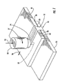
- FIG. 1 there is shown an apparatus for forming a joint 10 to connect first and second structural members 20, 22.
- Two structural members are typically joined by the method of the present invention, but a single structural member can be joined, for example, a tubular member or otherwise curved member with adjoining edges. Alternatively, three or more structural members can be joined, and the structural members can be arranged in various configurations.
- the first structural member 20 is disposed so that a faying surface 24 of the first structural member 20 overlaps a faying surface 26 of the second structural member 22 and the two structural members 20, 22 form an interface 28 therebetween.
- a friction welding tool is used to form a friction weld joint 12 between the structural members 20, 22.
- the friction welding tool can be a friction stir welding tool 50 that includes a rotatable pin 52 extending from a shoulder 54.
- the pin 52 is inserted through the interface 28 generally perpendicular to the interface 28, e.g., at an angle of about 3-5° from a line normal to the interface 28.
- An anvil (not shown) or other support can be disposed against the second structural member 22 to oppose the friction stir weld tool 50.
- the friction stir welding tool 50 is then urged in a direction 55 against the first structural member 20 and advanced in a direction 56 along the interface 28 of the structural members 20, 22 as the pin 52 rotates in a direction indicated by reference numeral 57.
- the motion of the pin 52 generates frictional heat, which plasticizes material from the structural members 20, 22, and the plasticized material is mixed by the pin 52.
- the friction stir weld joint 12 As the plasticized material cools and hardens, the friction stir weld joint 12 is formed, the friction stir weld joint 12 comprising part of the joint 10 that connects the two structural members 20, 22 as shown in Figure 2.
- the friction weld joint 12 includes a nugget region proximate to the path of the pin 52, the nugget region being characterized by a refined granular structure.
- the process of friction stir welding for joining structural members 20, 22 is known in the art and is described, for example, in U.S. Patent No. 5,460,317 to Thomas, et al., the entirety of which is incorporated herein by reference.
- the weld joint 12 formed by the configuration shown in Figure 1 is generally referred to as a lap joint, i.e., a joint generally perpendicular to the interface of overlapping members.
- other weld joints can alternatively be formed by friction stir welding.
- other types of friction welding such as linear friction welding, can also be used to join the members 20, 22, as can welding devices and methods other than friction welding devices and methods.
- the weld joint 12 can be formed by any welding technique such as laser welding or arc welding and, more particularly, gas tungsten arc welding, tungsten inert gas welding, plasma arc welding, or the like.
- the structural members 20, 22 can also be joined without welding, for example, by solder joints or braze joints.
- the structural members 20, 22 can be joined using connectors or fasteners including, e.g., rivets, bolts, screws, clips, crimps, and the like.
- the present invention is not limited to these or other types of joints, and instead can be used with a wide variety of joints for connecting structural members 20, 22.
- the structural members 20, 22 can define any of a variety of shapes such as sheets, plates, blocks, and the like.
- the members 20, 22 can be formed of metals, such as aluminum, titanium, alloys thereof, or steel.
- the members 20, 22 can be formed of non-metallic materials, including polymers, composite materials, and the like.
- the members 20, 22 can be formed of similar or dissimilar materials, i.e., each of the members 20, 22 can be formed of the same or different materials.
- one of the members 20, 22 is formed of a metallic material and is joined to another one of the members 20, 22 that is formed of a non-metallic material.
- the members 20, 22 can be joined to create an assembly used for various applications including frames, panels, skins, airfoils, and the like for aeronautical and aerospace structures such as aircraft and spacecraft, for marine vehicles, automobiles, and the like.
- the members 20, 22 are joined in geometrical configurations that make difficult, or prevent, subsequent access for inspecting or treating the joint 10.
- the structural members 20, 22 can be overlapped and joined to form a partially or fully closed body such as a tube or an airplane wing.
- a sealant 40 is disbetween the structural members 20, 22 at the interface 28 thereof.
- the sealant 40 can be disposed on one or both of the faying surfaces 24, 26 of the structural members 20, 22, and can be disposed over part or all of the area of the interface 28, including the region of the friction stir weld joint 12.
- the sealant 40 can fill the spaces 14 between the faying surfaces 24, 26 of the structural members 20, 22.
- the sealant 40 prevents chemicals, moisture, debris, and other substances from entering the spaces 14, and the sealant 40 thereby prevents corrosion or other damage that can be caused by those substances.
- the sealant 40 is formed of a material that can be chemically reacted exothermically.
- exothermically reactable materials can include beryllium, nickel, aluminum, boron, copper, magnesium, molybdenum, palladium, rhodium, silicon, titanium, zirconium, and the like.
- the sealant 40 can be formed of compounds or mixtures of titanium and boron; aluminum, nickel, and copper; nickel and aluminum; zirconium and aluminum; nickel and silicon; molybdenum and silicon; palladium and aluminum; rhodium and aluminum; titanium and aluminum; and the like.
- the sealant 40 can be ZrAl 3 , ZrAl 2 , TiAl, a mixture of titanium and boron, or various other exothermically reactable compounds, mixtures, and materials containing elements listed above and/or others.
- the sealant 40 can also include various chemicals, e.g., to prevent or reduce oxidation of metals in the sealant 40 and/or to at least temporarily bind the members 20, 22 so that a better metallic bond results in the joint 10.
- the energy released during the exothermic reaction can be sufficient for sustaining the reaction so that once the reaction is initiated, all or substantially all of the sealant 40 in the interface 28 reacts.
- the exothermic reaction of the sealant 40 can also be sufficient for melting the sealant 40 and/or portions of the structural members 20, 22, depending on the maximum reaction temperature of the sealant 40 and the melting temperature of the structural members 20, 22.
- the structural members 20, 22 are formed of aluminum or aluminum alloys and are sealed by a sealant 40 that reaches a maximum temperature of between about 1200 °F (649 °C) and 2000 °F (1093 °C) during the exothermic reaction.
- structural members 20, 22 formed of titanium or titanium alloys are sealed by a sealant 40 that reaches a maximum temperature of between about 2000 °F (1093 °C) and 3500 °F (1927 °C) during the exothermic reaction. Unalloyed aluminum and titanium melt at temperatures of about 1220 °F (660 °C) and 3270 °F (1799 °C), respectively. Therefore, in some cases, the sealant 40 partially melts the structural members 20, 22 at the interface 28 and forms a diffusion bond therewith. Alternatively, if the reaction temperature is less than the melting temperature of the structural members 20, 22, the sealant 40 can be melted to fill the interface 28 without melting the structural members 20, 22.
- the sealant 40 can substantially fill the interface 28, thereby sealing the interface 28 and preventing the entry of debris, moisture, and the like. Further, the sealant 40 can be joined to the structural members 20, 22 forming a joint therebetween. If the sealant 40 is reacted before friction welding of the structural members 20, 22, the joint formed by the sealant 40 can hold the structural members 20, 22 in place while friction welding is performed. Further, regardless of when the sealant 40 is reacted, the joint formed by the sealant 40 can enhance the strength of the overall joint 10 between the structural members 20, 22. That is, the sealant 40 can connect the structural members 20, 22 over a portion of the interface 28 that is not joined by friction welding, thereby supplementing the strength of the friction weld joint 12.
- the sealant 40 can be formed and disposed as a film, a paste, a powder, and the like.
- the sealant 40 can be formed as a foil or film having tens, hundreds, or thousands of layers.
- the sealant 40 can be formed as a paste or other fluid, such as a powder suspended in a plasticizer fluid.
- the sealant 40 can be disposed as a film, powder, fluid, or the like onto or in a substrate 42 that is subsequently used to dispose the sealant 40 onto one or both of the faying surfaces 24, 26.
- the substrate 42 can be a thin, flexible, tape-like sheet of polymer or paper material.
- the substrate 42 can be a porous or gauze-like material, which can at least partially absorb the sealant 40 therein.
- the sealant 40 can be disposed as a layer having uniform thickness on the substrate 42, and the substrate 42 can then be coiled to form a roll 44. Subsequently, the substrate 42 can be unrolled and placed on one or both of the structural members 20, 22 with the sealant 40 between the member 20, 22 and the substrate 42.
- the sealant 40 can be disposed on the substrate 42 as the substrate 42 is dispensed from a coil and/or by a feeder device, with the substrate 42 then being positioned on the structural member(s) 20, 22.
- the substrate 42 can be peeled from the member 22 in a direction 43, leaving the sealant 40 on the faying surface 26 .
- the structural members 20, 22 can be configured for joining with the substrate 42 therebetween, and the substrate 42 can be combusted or otherwise destroyed during the exothermic reaction of the sealant 40 and/or friction welding of the structural members 20, 22.
- the amount of sealant 40 disposed on the faying surfaces 24, 26 can vary, but in one embodiment of the invention, a layer of between about 0.0005 and 0.020 inches (0.00127 and 0.0508 cm) is disposed.
- the sealant 40 can be disposed over all or part of the faying surfaces 24, 26 , including the portion of the interface 28 that is welded to form the friction weld joint 12 of the joint 10 , although in some cases the sealant 40 may positively or negatively affect certain mechanical properties of the friction weld joint 12.
- the exothermic reaction of the sealant 40 can be initiated before, during, or after the structural members 20, 22 are friction welded to form the weld joint 12 .
- the sealant 40 is disposed on the faying surfaces 24, 26 , the structural members 20, 22 are positioned so that the faying surfaces 24, 26 are opposed to define the interface 28 therebetween, and the exothermic reaction is then initiated.
- Initiation of the exothermic reaction can be achieved by heating the sealant 40, providing a chemical catalyst, or the like.
- an oven, flame, laser, or the like can be used to heat all or part of the sealant 40 and/or the structural members 20, 22 to an initiation temperature of the sealant 40 at which the exothermic reaction begins to take place.
- the exothermic reaction releases sufficient thermal energy to sustain the reaction, and therefore no additional energy need be supplied.
- the reaction is exothermic but does not release sufficient thermal energy to be self-sustaining, and therefore additional energy must be supplied, e.g., with the oven, flame, laser, or the like. If the exothermic reaction is self-sustaining, the reaction typically occurs quickly once initiated. Friction welding can then be performed as described above.
- the friction welding can be performed at least partially during the exothermic reaction.
- the sealant 40 can be disposed, the structural members 20, 22 can be positioned to define the interface 28, and the friction welding can then be performed such that the friction welding provides sufficient thermal energy to initiate the exothermic reaction.
- the exothermic reaction can then occur at a rate that is equal to or different than the rate of the friction welding. For example, once initiated, the exothermic reaction of the sealant 40 may finish within a few seconds or less, while the friction welding continues at a slower rate.
- the sealant 40 can be reacted after the friction welding has begun or ended.
- the sealant 40 is disposed on the faying surfaces 24, 26, the structural members 20, 22 are positioned with the faying surfaces 24, 26 opposed to form the interface 28 therebetween, and the friction weld joint 12 is formed. Subsequent to forming at least part of the friction weld joint 12, the sealant 40 is exothermically reacted to form the seal in the interface 28.
- the sealant 40 substantially fills the interface 28 and thereby seals the interface 28 to prevent moisture and debris from entering the interface 28 .
- the sealant 40 can form a seal 46 that extends outside the interface 28, e.g., at one or more edges of the interface 28 to further protect the interface 28 from corrosion or other damage to the structural members 20, 22 .
- the sealant 40 can be disposed outside the interface 28 .
- the sealant 40 can be disposed on portions of the structural members 20, 22 that are extend beyond the area of the faying surfaces 24, 26 .
- the sealant 40 is disposed as a paste onto the faying surfaces 24, 26 , and the structural members 20, 22 are positioned with the faying surfaces 24, 26 in an opposed configuration to define the interface 28.
- the structural members 20, 22 are then urged together, for example, by clamping the structural members 20, 22 together.
- the paste sealant 40 substantially fills the interface 28 and some of the sealant 40 is squeezed from the interface 28 at the edges of the interface 28 . Excess paste sealant 40 can be removed from the edges of the interface 28, but some sealant 40 is left outside the interface 28.
- a bead of sealant 40 at the edge of the interface 28 forms a fillet seal 46.
- such a fillet seal 46 can alternatively be formed using conventional sealants, such as a caulk-like or resinous material.
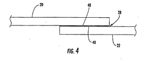
- a braze material 48 can also be provided in the interface 28 with the sealant 40 before the sealant 40 is reacted to form a braze joint between the structural members 20, 22 .
- the braze material 48 is characterized by a melting temperature that is lower than the melting temperature of the structural members 20, 22 .
- the particular braze material 48 for a particular joint 10 can be selected according to the materials of the structural members 20, 22 and the sealant 40 .
- the braze material 48 can include bronze, copper, aluminum, and/or nickel.
- the braze material 48 can be provided as part of the foil, paste, powder, or other constitution of the sealant 40.
- thin sheets of the braze material 48 can be layered within the foil of the sealant 40 , or particles of the braze material 48 can be mixed with a sealant 40 that is a powder or paste.
- the braze material 48 can be disposed onto one or both of the faying surfaces 24, 26 together with the sealant 40.
- the braze material 48 can be provided separately in the interface 28, e.g., as a separate sheet that is layered with the foil sealant 40 , as a powder or paste that is disposed on the faying surface opposite the sealant 40, or otherwise.
- the sealant 40 can have a reaction temperature that is higher than the melting temperature of the braze material 48, and the sealant 40 can be disposed in a quantity such that sufficient heat is released during the exothermic reaction to melt the braze material 48 so that the braze material 48 is brazed or otherwise bonded to the structural members 20, 22, thereby joining the structural members 20, 22.
- the joint 12 can be formed, as described above, e.g., by friction stir welding.
- the braze material 48 enhances the strength of the joint 10 between the structural members 20, 22.
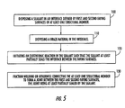
- Figure 5 illustrates the operations for forming a joint according to one embodiment of the present invention. It is understood that some of the operations can be omitted from the method, and additional operations can be performed, without departing from the scope of the present invention.
- a sealant is disposed in an interface defined by first and second faying surfaces of at least one structural member.
- the sealant can be disposed as a foil or fluid, and can be disposed with a substrate.
- the sealant can be disposed with a thickness of between about 0.0005 and 0.020 inches (0.00127 and 0.0508 cm) and can fill, or substantially fill, the entire interface.
- sealant can be disposed outside the interface, e.g., by squeezing the members together after disposing the sealant, so that the sealant forms a fillet seal outside the interface.
- a braze material is also disposed in the interface with the sealant. See Block 110.
- An exothermic reaction of the sealant is initiated so that the sealant at least partially seals the interface between the faying surfaces. See Block 120.
- the reaction can be initiated by heating the sealant to an initiation temperature.
- the exothermic reaction is characterized by a maximum temperature of at least about 1200 °F (649 °C).
- the at least one structural member is welded or otherwise connected to form a joint between the first and second faying surfaces, the joint being at least partially sealed by the sealant. See Block 130.
- the structural member(s) can be friction stir welded. The friction welding can initiate the exothermic reaction of the sealant, or the sealant can be reacted before or after the friction welding.
- the structural member(s) can be welded by any other welding technique such as laser welding or arc welding and, more particularly, gas tungsten arc welding, tungsten inert gas welding, plasma arc welding, or the like.
- the structural members can also be joined without welding, for example, by soldering, brazing, or disposing connectors or fasteners such as rivets, bolts, screws, or clips between the structural members.
Landscapes
- Engineering & Computer Science (AREA)
- Mechanical Engineering (AREA)
- Chemical & Material Sciences (AREA)
- Chemical Kinetics & Catalysis (AREA)
- Pressure Welding/Diffusion-Bonding (AREA)
- Building Environments (AREA)
- Lining Or Joining Of Plastics Or The Like (AREA)
Abstract
Description
- The present invention relates to the joining of structural members and, more particularly, relates to the sealing of joints between structural members, for example, to increase the strength and corrosion-resistance of the members.
- The joining of structural members often results in an interface that is susceptible to intrusion by chemicals, moisture, or other fluids and particulates. For example, in the aircraft industry, joints between structural members are often formed by overlapping two or more structural members, forming holes through the members, and disposing rivets or other fasteners through the holes. Although the overlapping members may correspond closely to one another at their interface, each interface nevertheless typically defines a narrow space or crevice-like gap through which moisture, chemicals, debris, and other foreign materials can be received, possibly resulting in increased corrosion of the structural members and the fasteners. Therefore, a sealant such as a caulk-like organic material can be disposed in each interface to seal the interface and prevent the entry of foreign materials therein. The sealant can be disposed before or after the joint is formed, though in some cases the sealant is preferably disposed before joining because the geometrical configuration of the structural members may prevent access to one or both sides of the interface after joining. In some cases, the sealant may be squeezed from the interface during joining, leaving unfilled voids in the interface, which can be difficult to identify and fill, especially if one or both sides of the joint cannot be accessed after joining. Further, even if the sealant does fill the interface, the sealant can dry out and deteriorate or otherwise work free from the joint over time.
- Joints can alternatively be formed by welding the structural members. For example, a friction stir weld joint can be formed by overlapping the structural members, rotating a friction stir welding pin extending in a direction generally perpendicular to the interface of the members, and urging the pin through the members along the interface. The pin generates sufficient friction with the structural members to plasticize a portion of the members, and the plasticized material is mixed by the pin. As the plasticized material cools, a friction stir weld joint is formed, characterized by a mixed portion having a refined grain structure, referred to as a nugget. The nugget is typically not as wide as the interface of the overlapping members, and the members therefore define spaces in the interface in which corrosion can occur, similar to the space proximate to the rivet joints described above. A sealant can be disposed in the spaces; however, if the sealant is disposed before welding, care should be taken to avoid introducing the sealant into the nugget of the joint as conventional sealants can negatively impact the strength and/or corrosion resistance of the joint. For example, masking tape can be placed on the area of the structural members where the nugget will be formed, the sealant can be disposed on the structural members, and the masking tape can then be removed to generally leave a clean area for forming the nugget. This process is time consuming. Further, even if such precautions are taken, as the members are placed and urged together to form the joint, some of the sealant can be squeezed into the interface and mixed with the plasticized material of the joint, thereby reducing the quality of the weld joint. In addition, as described above, voids can result in the interface during joining or the sealant can be loosened from the interface subsequently.
- Thus, there exists a need for an improved method for forming a corrosion resistant joint in a structural member. The method should be compatible with welded methods, such as friction welding, and should not be overly time consuming. Further, the method should result in a strong bond between the structural members without excessively reducing the quality of the joint.
- An object of the invention is therefore to provide an improved method for forming a joint in a structural member. This object is achieved by a method according to claim 1 or claim 24. Advantageous features and their combinations are described in the claims dependent therefrom.
- A further object is to provide an improved strong bond between the structural members. This object is achieved by a joint according to claim 47 or claim 56. Advantageous embodiments and their combinations are described in the dependent claims.
- The present invention provides a sealed joint and a method for forming a joint between structural members. A sealant formed of an exothermic material is disposed in an interface between faying surfaces of the structural members and reacted to form a seal and/or a bond in the interface. The sealant can fill the spaces between the structural members to prevent the entry of chemicals, moisture, debris, and other substances, thereby reducing the likelihood of corrosion of the joint or structural members at the interface. Further, the sealant can be reacted before, during, or after the formation of a joint, such as a friction stir weld joint, between the members.
- According to one embodiment of the present invention, the joint is formed by disposing the sealant in the interface and exothermically reacting the sealant in the interface. The structural members, which can be formed of a variety of materials including aluminum, aluminum alloys, titanium, titanium alloys, steel, and the like, are friction welded to form a joint between the faying surfaces, with the joint being least partially sealed by the sealant.
- The sealant, which can include aluminum, nickel, oxygen, or other materials, can be disposed as a foil, such as a multilayer foil, or as a fluid that can include a plasticizer. Further, the sealant can be provided on a substrate that is then used to dispose the sealant onto one or both of the faying surfaces. The sealant can be disposed with a thickness of between about 0.0005 and 0.020 inches (0.00127 and 0.0508 cm), and some of the sealant can be reacted outside the interface to form a fillet seal on one or more edges of the interface. For example, the faying surfaces can be urged together before the sealant is reacted so that some of the sealant is squeezed from the interface and subsequently exothermically reacted to form a seal on at least one edge of the interface.
- The exothermic reaction of the sealant can be initiated by heating the sealant to an initiation temperature, and can be initiated before, during, or after motion welding the structural members. For example, friction stir welding of the structural members can heat the members to the initiation temperature and thereby start the exothermic reaction. The exothermic reaction of the sealant can have a maximum temperature that reaches or exceeds about 1200 °F (649 °C).
- In addition, a braze material can be provided in the interface with the sealant. The braze material has a melting temperature that is generally lower than a melting temperature of the structural members so that the braze material is bonded to the faying surfaces during the exothermic reaction of the sealant. The braze material can include, e.g., bronze, copper, aluminum, or nickel.
- According to other embodiments of the invention, other connections can be formed between the structural members and sealed. For example, the structural members can be joined by other types of friction welding such as linear friction welding, other types of welding such as laser welding or arc welding, connectors or fasteners such as rivets or bolts, or the like.
- The present invention also provides a weld joint that connects first and second faying surfaces of one or more structural members formed of materials such as aluminum, aluminum alloys, titanium, titanium alloys, or steel. A friction weld joint connects the faying surfaces at the interface, and an exothermically reacted sealant in the interface at least partially seals the friction weld joint therein. The sealant, which can include materials such as aluminum, nickel, and oxygen, can substantially fill the interface. Further, the sealant can seal the faying surfaces outside the interface, e.g., as a fillet seal on the edges of the interface. The friction weld joint can be a friction stir welded joint having a nugget area characterized by a refined granular structure, and the friction weld joint can extend through the structural members in a direction substantially perpendicular to the interface. Further, a braze joint formed of bronze, copper, aluminum, nickel, or the like can be provided between the faying surfaces proximate to the friction weld joint such that the braze joint at least partially seals the interface.
- Having thus described the invention in general terms, reference will now be made to the accompanying drawings, which are not necessarily drawn to scale, and wherein:
- Figure 1 is a perspective view illustrating two structural members partially joined by a friction weld joint according to one embodiment of the present invention;
- Figure 2 is a section view in elevation of the weld joint between the structural members of Figure 1;
- Figure 3 is a perspective view illustrating a sealant partially disposed on a structural member according to another embodiment of the present invention;
- Figure 4 is a section view in elevation of two structural members configured for joining according to another embodiment of the present invention; and
- Figure 5 is a block diagram illustrating the operations for forming a joint according to one embodiment of the present invention.
-
- The present invention now will be described more fully hereinafter with reference to the accompanying drawings, in which some, but not all embodiments of the invention are shown. Indeed, this invention may be embodied in many different forms and should not be construed as limited to the embodiments set forth herein; rather, these embodiments are provided so that this disclosure will satisfy applicable legal requirements. Like numbers refer to like elements throughout.
- Referring now to the figures and, in particular, Figure 1, there is shown an apparatus for forming a joint 10 to connect first and second
structural members structural member 20 is disposed so that afaying surface 24 of the firststructural member 20 overlaps afaying surface 26 of the secondstructural member 22 and the twostructural members interface 28 therebetween. A friction welding tool is used to form a friction weld joint 12 between thestructural members stir welding tool 50 that includes arotatable pin 52 extending from ashoulder 54. Thepin 52 is inserted through theinterface 28 generally perpendicular to theinterface 28, e.g., at an angle of about 3-5° from a line normal to theinterface 28. An anvil (not shown) or other support can be disposed against the secondstructural member 22 to oppose the frictionstir weld tool 50. The frictionstir welding tool 50 is then urged in adirection 55 against the firststructural member 20 and advanced in adirection 56 along theinterface 28 of thestructural members pin 52 rotates in a direction indicated byreference numeral 57. The motion of thepin 52 generates frictional heat, which plasticizes material from thestructural members pin 52. As the plasticized material cools and hardens, the friction stir weld joint 12 is formed, the friction stir weld joint 12 comprising part of the joint 10 that connects the twostructural members pin 52, the nugget region being characterized by a refined granular structure. - The process of friction stir welding for joining
structural members members structural members structural members structural members - The
structural members members members members members members members members members structural members - Although the faying surfaces 24, 26 of the
structural members interface 28 is characterized by spaces orvoids 14 between thesurfaces sealant 40 is disbetween thestructural members interface 28 thereof. Thesealant 40 can be disposed on one or both of the faying surfaces 24, 26 of thestructural members interface 28, including the region of the friction stir weld joint 12. Thus, thesealant 40 can fill thespaces 14 between the faying surfaces 24, 26 of thestructural members sealant 40 prevents chemicals, moisture, debris, and other substances from entering thespaces 14, and thesealant 40 thereby prevents corrosion or other damage that can be caused by those substances. - Preferably, the
sealant 40 is formed of a material that can be chemically reacted exothermically. Such exothermically reactable materials can include beryllium, nickel, aluminum, boron, copper, magnesium, molybdenum, palladium, rhodium, silicon, titanium, zirconium, and the like. For example, thesealant 40 can be formed of compounds or mixtures of titanium and boron; aluminum, nickel, and copper; nickel and aluminum; zirconium and aluminum; nickel and silicon; molybdenum and silicon; palladium and aluminum; rhodium and aluminum; titanium and aluminum; and the like. In particular, thesealant 40 can be ZrAl3, ZrAl2, TiAl, a mixture of titanium and boron, or various other exothermically reactable compounds, mixtures, and materials containing elements listed above and/or others. Thesealant 40 can also include various chemicals, e.g., to prevent or reduce oxidation of metals in thesealant 40 and/or to at least temporarily bind themembers - The energy released during the exothermic reaction can be sufficient for sustaining the reaction so that once the reaction is initiated, all or substantially all of the
sealant 40 in theinterface 28 reacts. The exothermic reaction of thesealant 40 can also be sufficient for melting thesealant 40 and/or portions of thestructural members sealant 40 and the melting temperature of thestructural members structural members sealant 40 that reaches a maximum temperature of between about 1200 °F (649 °C) and 2000 °F (1093 °C) during the exothermic reaction. In another embodiment,structural members sealant 40 that reaches a maximum temperature of between about 2000 °F (1093 °C) and 3500 °F (1927 °C) during the exothermic reaction. Unalloyed aluminum and titanium melt at temperatures of about 1220 °F (660 °C) and 3270 °F (1799 °C), respectively. Therefore, in some cases, thesealant 40 partially melts thestructural members interface 28 and forms a diffusion bond therewith. Alternatively, if the reaction temperature is less than the melting temperature of thestructural members sealant 40 can be melted to fill theinterface 28 without melting thestructural members - In either case, the
sealant 40 can substantially fill theinterface 28, thereby sealing theinterface 28 and preventing the entry of debris, moisture, and the like. Further, thesealant 40 can be joined to thestructural members sealant 40 is reacted before friction welding of thestructural members sealant 40 can hold thestructural members sealant 40 is reacted, the joint formed by thesealant 40 can enhance the strength of the overall joint 10 between thestructural members sealant 40 can connect thestructural members interface 28 that is not joined by friction welding, thereby supplementing the strength of the friction weld joint 12. - The
sealant 40 can be formed and disposed as a film, a paste, a powder, and the like. For example, thesealant 40 can be formed as a foil or film having tens, hundreds, or thousands of layers. Alternatively, thesealant 40 can be formed as a paste or other fluid, such as a powder suspended in a plasticizer fluid. Further, thesealant 40 can be disposed as a film, powder, fluid, or the like onto or in asubstrate 42 that is subsequently used to dispose thesealant 40 onto one or both of the faying surfaces 24, 26. As illustrated in Figure 3, thesubstrate 42 can be a thin, flexible, tape-like sheet of polymer or paper material. Alternatively, thesubstrate 42 can be a porous or gauze-like material, which can at least partially absorb thesealant 40 therein. As shown in Figure 3, thesealant 40 can be disposed as a layer having uniform thickness on thesubstrate 42, and thesubstrate 42 can then be coiled to form aroll 44. Subsequently, thesubstrate 42 can be unrolled and placed on one or both of thestructural members sealant 40 between themember substrate 42. In other embodiments, thesealant 40 can be disposed on thesubstrate 42 as thesubstrate 42 is dispensed from a coil and/or by a feeder device, with thesubstrate 42 then being positioned on the structural member(s) 20, 22. As shown in Figure 3, thesubstrate 42 can be peeled from themember 22 in a direction 43, leaving thesealant 40 on thefaying surface 26. Alternatively, thestructural members substrate 42 therebetween, and thesubstrate 42 can be combusted or otherwise destroyed during the exothermic reaction of thesealant 40 and/or friction welding of thestructural members - The amount of
sealant 40 disposed on the faying surfaces 24, 26 can vary, but in one embodiment of the invention, a layer of between about 0.0005 and 0.020 inches (0.00127 and 0.0508 cm) is disposed. Thesealant 40 can be disposed over all or part of the faying surfaces 24, 26, including the portion of theinterface 28 that is welded to form the friction weld joint 12 of the joint 10, although in some cases thesealant 40 may positively or negatively affect certain mechanical properties of the friction weld joint 12. - The exothermic reaction of the
sealant 40 can be initiated before, during, or after thestructural members sealant 40 is disposed on the faying surfaces 24, 26, thestructural members interface 28 therebetween, and the exothermic reaction is then initiated. Initiation of the exothermic reaction can be achieved by heating thesealant 40, providing a chemical catalyst, or the like. For example, an oven, flame, laser, or the like can be used to heat all or part of thesealant 40 and/or thestructural members sealant 40 at which the exothermic reaction begins to take place. As noted above, in some embodiments the exothermic reaction releases sufficient thermal energy to sustain the reaction, and therefore no additional energy need be supplied. In other embodiments, however, the reaction is exothermic but does not release sufficient thermal energy to be self-sustaining, and therefore additional energy must be supplied, e.g., with the oven, flame, laser, or the like. If the exothermic reaction is self-sustaining, the reaction typically occurs quickly once initiated. Friction welding can then be performed as described above. - In other embodiments of the invention, the friction welding can be performed at least partially during the exothermic reaction. In particular, the
sealant 40 can be disposed, thestructural members interface 28, and the friction welding can then be performed such that the friction welding provides sufficient thermal energy to initiate the exothermic reaction. The exothermic reaction can then occur at a rate that is equal to or different than the rate of the friction welding. For example, once initiated, the exothermic reaction of thesealant 40 may finish within a few seconds or less, while the friction welding continues at a slower rate. - Alternatively, if the friction welding does not provide sufficient thermal energy to initiate the exothermic reaction of the
sealant 40, thesealant 40 can be reacted after the friction welding has begun or ended. For example, according to one embodiment of the invention, thesealant 40 is disposed on the faying surfaces 24, 26, thestructural members interface 28 therebetween, and the friction weld joint 12 is formed. Subsequent to forming at least part of the friction weld joint 12, thesealant 40 is exothermically reacted to form the seal in theinterface 28. - Preferably, the
sealant 40 substantially fills theinterface 28 and thereby seals theinterface 28 to prevent moisture and debris from entering theinterface 28. Further, as shown in Figure 2, thesealant 40 can form aseal 46 that extends outside theinterface 28, e.g., at one or more edges of theinterface 28 to further protect theinterface 28 from corrosion or other damage to thestructural members sealant 40 can be disposed outside theinterface 28. For example, if thesealant 40 is disposed as a foil or paste-like fluid, thesealant 40 can be disposed on portions of thestructural members sealant 40 is disposed as a paste onto the faying surfaces 24, 26, and thestructural members interface 28. Thestructural members structural members paste sealant 40 substantially fills theinterface 28 and some of thesealant 40 is squeezed from theinterface 28 at the edges of theinterface 28.Excess paste sealant 40 can be removed from the edges of theinterface 28, but somesealant 40 is left outside theinterface 28. Thus, when thepaste sealant 40 is reacted, a bead ofsealant 40 at the edge of theinterface 28 forms afillet seal 46. In other embodiments of the present invention, such afillet seal 46 can alternatively be formed using conventional sealants, such as a caulk-like or resinous material. - As illustrated in Figure 4, a
braze material 48 can also be provided in theinterface 28 with thesealant 40 before thesealant 40 is reacted to form a braze joint between thestructural members braze material 48 is characterized by a melting temperature that is lower than the melting temperature of thestructural members particular braze material 48 for a particular joint 10 can be selected according to the materials of thestructural members sealant 40. For example, thebraze material 48 can include bronze, copper, aluminum, and/or nickel. Thebraze material 48 can be provided as part of the foil, paste, powder, or other constitution of thesealant 40. For example, thin sheets of thebraze material 48 can be layered within the foil of thesealant 40, or particles of thebraze material 48 can be mixed with asealant 40 that is a powder or paste. Thus, thebraze material 48 can be disposed onto one or both of the faying surfaces 24, 26 together with thesealant 40. Alternatively, thebraze material 48 can be provided separately in theinterface 28, e.g., as a separate sheet that is layered with thefoil sealant 40, as a powder or paste that is disposed on the faying surface opposite thesealant 40, or otherwise. In any case, thesealant 40 can have a reaction temperature that is higher than the melting temperature of thebraze material 48, and thesealant 40 can be disposed in a quantity such that sufficient heat is released during the exothermic reaction to melt thebraze material 48 so that thebraze material 48 is brazed or otherwise bonded to thestructural members structural members sealant 40 and, hence, the joining of thestructural members braze material 48, the joint 12 can be formed, as described above, e.g., by friction stir welding. Thus, thebraze material 48 enhances the strength of the joint 10 between thestructural members - Figure 5 illustrates the operations for forming a joint according to one embodiment of the present invention. It is understood that some of the operations can be omitted from the method, and additional operations can be performed, without departing from the scope of the present invention. As indicated in
Block 100, a sealant is disposed in an interface defined by first and second faying surfaces of at least one structural member. The sealant can be disposed as a foil or fluid, and can be disposed with a substrate. The sealant can be disposed with a thickness of between about 0.0005 and 0.020 inches (0.00127 and 0.0508 cm) and can fill, or substantially fill, the entire interface. Further, some of the sealant can be disposed outside the interface, e.g., by squeezing the members together after disposing the sealant, so that the sealant forms a fillet seal outside the interface. In some embodiments of the invention, a braze material is also disposed in the interface with the sealant.See Block 110. An exothermic reaction of the sealant is initiated so that the sealant at least partially seals the interface between the faying surfaces. See Block 120. For example, the reaction can be initiated by heating the sealant to an initiation temperature. In one embodiment, the exothermic reaction is characterized by a maximum temperature of at least about 1200 °F (649 °C). The at least one structural member is welded or otherwise connected to form a joint between the first and second faying surfaces, the joint being at least partially sealed by the sealant.See Block 130. For example, the structural member(s) can be friction stir welded. The friction welding can initiate the exothermic reaction of the sealant, or the sealant can be reacted before or after the friction welding. Alternatively, the structural member(s) can be welded by any other welding technique such as laser welding or arc welding and, more particularly, gas tungsten arc welding, tungsten inert gas welding, plasma arc welding, or the like. Further, the structural members can also be joined without welding, for example, by soldering, brazing, or disposing connectors or fasteners such as rivets, bolts, screws, or clips between the structural members. - Many modifications and other embodiments of the invention set forth herein will come to mind to one skilled in the art to which this invention pertains having the benefit of the teachings presented in the foregoing descriptions and the associated drawings. Therefore, it is to be understood that the invention is not to be limited to the specific embodiments disclosed and that modifications and other embodiments are intended to be included within the scope of the appended claims. Although specific terms are employed herein, they are used in a generic and descriptive sense only and not for purposes of limitation.
Claims (65)
- A method of forming a weld joint, the method comprising:disposing a sealant in an interface defined by first and second faying surfaces of at least one structural member;initiating an exothermic reaction in the sealant such that the sealant at least partially seals the interface between the faying surfaces; andfriction welding the at least one structural member to form a joint between the first and second faying surfaces, the joint being at least partially sealed by the sealant.
- A method according to Claim 1 further comprising providing the sealant, the sealant comprising at least one of the group consisting of aluminum, nickel, and oxygen.
- A method according to Claim 1 or Claim 2, wherein said initiating step comprises filling substantially the entire interface with the sealant.
- A method according to one of Claims 1 to 3, wherein said friction welding step comprises rotating a friction stir welding pin extending from a shoulder and urging the pin through the interface to thereby friction stir weld the at least one structural member.
- A method according to one of Claims 1 to 3, wherein said friction welding step comprises urging a friction welding tool through the faying surfaces in a direction substantially perpendicular to the interface.
- A method according to one of the preceding Claims wherein said disposing step comprises disposing the sealant as a foil between the faying surfaces.
- A method according to Claim 6 further comprising forming the sealant, said forming step comprising layering a plurality of laminar sheets of the sealant to form a multilayer foil.
- A method according to one of Claims 1 to 5, wherein said disposing step comprises disposing the sealant as a fluid on at least one of the faying surfaces.
- A method according to Claim 8 further comprising providing the sealant as the fluid, the fluid including a plasticizer.
- A method according to one of the preceding Claims, further comprising providing the sealant on a substrate, and wherein said disposing step comprises disposing the sealant and the substrate onto at least one of the faying surfaces.
- A method according to Claim 10 further comprising removing the substrate from the faying surface prior to said motion welding step such that the sealant remains on the faying surface.
- A method according to one of the preceding Claims, wherein said initiating step comprises heating the sealant to an initiation temperature of the sealant and thereby initiating the exothermic reaction of the sealant.
- A method according to one of the preceding Claims, wherein said initiating step is performed prior to said friction welding step such that the exothermic reaction of the sealant substantially terminates before the sealant is friction welded.
- A method according to one of Claims 1 to 12, wherein said initiating step is performed concurrently with said friction welding step.
- A method according to Claim 14 wherein said initiating step comprises heating the sealant to an initiation temperature of the sealant by friction stir welding.
- A method according to one of Claims 1 to 12, wherein said initiating step is performed subsequent to said friction welding step.
- A method according to one of the preceding Claims, further comprising providing the at least one structural member, the structural member comprising at least one of the group consisting of aluminum, aluminum alloys, titanium, titanium alloys, and steel.
- A method according to one of the preceding Claims further comprising disposing a braze material in the interface, the braze material having a melting temperature lower than a melting temperature of the structural member and the braze material being at least partially bonded to the faying surfaces during an exothermic reaction of the sealant.
- A method according to Claim 18 further comprising providing the braze material, the braze material comprising at least one of the group consisting of bronze, copper, aluminum, and nickel.
- A method according to one of the preceding Claims wherein said initiating step comprises initiating an exothermic reaction of the sealant, the reaction having a maximum temperature of at least about 1200 °F (649 °C).
- A method according to one of the preceding Claims wherein said disposing step comprises disposing the sealant having a thickness of between about 0.0005 and 0.020 inches (0.00127 and 0.0508 cm).
- A method according to one of the preceding Claims wherein said initiating step comprises reacting at least some of the sealant outside the interface to form a fillet seal on at least one edge of the interface.
- A method according to one of the preceding Claims further comprising urging said faying surfaces together before said initiating step such that some of the sealant is squeezed from the interface and subsequently exothermically reacted to form a seal on at least one edge of the interface.
- A method of forming a joint between at least one structural member, the method comprising:disposing a sealant in an interface defined by first and second faying surfaces of the at least one structural member;initiating an exothermic reaction in the sealant such that the sealant at least partially seals the interface between the faying surfaces; andjoining the at least one structural member to form a joint between the first and second faying surfaces, the joint being at least partially sealed by the sealant.
- A method according to Claim 24 further comprising providing the sealant, the sealant comprising at least one of the group consisting of aluminum, nickel, and oxygen.
- A method according to Claim 24 or Claim 25, wherein said initiating step comprises filling substantially the entire interface with the sealant.
- A method according to one of Claims 24 to 26, wherein said joining step comprises welding the structural members at the interface for form a weld joint between the structural members.
- A method according to Claim 27 wherein said welding step comprises at least one of the group consisting of arc welding and laser welding.
- A method according to Claim 27 or Claim 28, wherein said initiating step comprises heating the sealant to an initiation temperature of the sealant by said welding step.
- A method according to one of Claims 24 to 26, wherein said joining step comprises disposing at least one connector through the interface to join the structural members.
- A method according to one of Claims 24 to 30, wherein said disposing step comprises disposing the sealant as a foil between the faying surfaces.
- A method according to Claim 31 further comprising forming the sealant, said forming step comprising layering a plurality of laminar sheets of the sealant to form a multilayer foil.
- A method according to one of Claims 24 to 30, wherein said disposing step comprises disposing the sealant as a fluid on at least one of the faying surfaces.
- A method according to Claim 33 further comprising providing the sealant as the fluid, the fluid including a plasticizer.
- A method according to one of Claims 24 to 34, further comprising providing the sealant on a substrate, and wherein said disposing step comprises disposing the sealant and the substrate onto at least one of the faying surfaces.
- A method according to Claim 35 further comprising removing the substate from the faying surface prior to said joining step such that the sealant remains on the faying surface.
- A method according to one of Claims 24 to 36, wherein said initiating step comprises heating the sealant to an initiation temperature of the sealant and thereby initiating the exothermic reaction of the sealant.
- A method according to one of Claims 24 to 37, wherein said initiating step is performed prior to said joining step.
- A method according to one of Claims 24 to 37, wherein said initiating step is performed subsequent to said joining step.
- A method according to one of Claims 24 to 39, further comprising providing the at least one structural member, the structural member comprising at least one of the group consisting of aluminum, aluminum alloys, titanium, titanium alloys, and steel.
- A method according to one of Claims 24 to 40, further comprising disposing a braze material in the interface, the braze material having a melting temperature lower than a melting temperature of the structural member and the braze material being at least partially bonded to the faying surfaces during an exothermic reaction of the sealant.
- A method according to Claim 41 further comprising providing the braze material, the braze material comprising at least one of the group consisting of bronze, copper, aluminum, and nickel.
- A method according to one of Claims 24 to 42, wherein said initiating step comprises initiating an exothermic reaction of the sealant, the reaction having a maximum temperature of at least about 1200 °F (649 °C).
- A method according to one of Claims 24 to 43, wherein said disposing step comprises disposing the sealant having a thickness of between about 0.0005 and 0.020 inches (0.00127 and 0.0508 cm).
- A method according to one of Claims 24 to 44, wherein said initiating step comprises reacting at least some of the sealant outside the interface to form a fillet seal on at least one edge of the interface.
- A method according to one of Claims 24 to 45, further comprising urging said faying surfaces together before said initiating step such that some of the sealant is squeezed from the interface and subsequently exothermically reacted to form a seal on at least one edge of the interface.
- A weld joint connecting first and second faying surfaces of at least one structural member defining an interface therebetween, the weld joint comprising:a friction weld joint connecting the faying surfaces at the interface of the faying surfaces; andan exothermically reacted sealant disposed in the interface between the faying surfaces and at least partially sealing the friction weld joint in the interface.
- A joint according to Claim 47 wherein the sealant comprises a product of at least one of the group consisting of aluminum, nickel, and oxygen.
- A joint according to Claim 47 or Claim 48, wherein the sealant substantially fills the interface.
- A joint according to one of Claims 47 to 49, wherein the sealant seals the faying surfaces outside the interface.
- A joint according to one of Claims 47 to 50, wherein the friction weld joint comprises a nugget area formed by friction stir welding and characterized by a refined granular structure.
- A joint according to one of Claims 47 to 51, wherein the friction weld joint extends through the at least one structural member in a direction substantially perpendicular to the interface.
- A joint according to one of Claims 47 to 52, wherein the at least one structural member is formed of at least one of the group consisting of aluminum, aluminum alloys, titanium, titanium alloys, and steel.
- A joint according to one of Claims 47 to 53, further comprising a braze joint between the faying surfaces proximate to the friction weld joint, the braze joint at least partially sealing the interface.
- A joint according to Claim 54 wherein the braze joint is formed of at least one of the group consisting of bronze, copper, aluminum, and nickel.
- A joint connecting first and second faying surfaces of at least one structural member defining an interface therebetween, the joint comprising:a connection extending between the faying surfaces of the at least one structural member at the interface of the faying surfaces and connecting the faying surfaces; andan exothermically reacted sealant disposed in the interface between the faying surfaces and at least partially sealing the connection in the interface.
- A joint according to Claim 56 wherein the sealant comprises a product of at least one of the group consisting of aluminum, nickel, and oxygen.
- A joint according to Claim 56 or Claim 57, wherein the sealant substantially fills the interface.
- A joint according to one of Claims 56 to 58, wherein the sealant seals the faying surfaces outside the interface.
- A joint according to one of Claims 56 to 59, wherein the connection comprises a weld joint formed by at least one of the group consisting of laser welding and arc welding.
- A joint according to one of Claims 56 to 60, wherein the connection comprises at least one connector extending between the at least one structural member, each connector comprising at least one of the group consisting of bolts and rivets.
- A joint according to one of Claims 56 to 61, wherein the at least one structural member is formed of at least one of the group consisting of aluminum, aluminum alloys, titanium, titanium alloys, and steel.
- A joint according to one of Claims 56 to 62, wherein the at least one structural member comprises at least one non-metallic structural member.
- A joint according to one of Claims 56 to 63, further comprising a braze joint between the faying surfaces proximate to the friction weld joint, the braze joint at least partially sealing the interface.
- A joint according to Claim 64 wherein the braze joint is formed of at least one of the group consisting of bronze, copper, aluminum, and nickel.
Applications Claiming Priority (2)
| Application Number | Priority Date | Filing Date | Title |
|---|---|---|---|
| US657775 | 2003-08-29 | ||
| US10/657,775 US7090112B2 (en) | 2003-08-29 | 2003-08-29 | Method and sealant for joints |
Publications (4)
| Publication Number | Publication Date |
|---|---|
| EP1510281A2 true EP1510281A2 (en) | 2005-03-02 |
| EP1510281A3 EP1510281A3 (en) | 2005-06-01 |
| EP1510281B1 EP1510281B1 (en) | 2008-06-11 |
| EP1510281B2 EP1510281B2 (en) | 2011-04-13 |
Family
ID=31978975
Family Applications (1)
| Application Number | Title | Priority Date | Filing Date |
|---|---|---|---|
| EP03027702A Expired - Lifetime EP1510281B2 (en) | 2003-08-29 | 2003-12-02 | Method of friction stir welding using an exothermically reactive sealant and friction stir weld joint having an exothermically reacted sealant |
Country Status (6)
| Country | Link |
|---|---|
| US (1) | US7090112B2 (en) |
| EP (1) | EP1510281B2 (en) |
| JP (1) | JP3793536B2 (en) |
| KR (1) | KR100570312B1 (en) |
| CN (1) | CN1305630C (en) |
| DE (1) | DE60321566D1 (en) |
Families Citing this family (58)
| Publication number | Priority date | Publication date | Assignee | Title |
|---|---|---|---|---|
| DE10036170C1 (en) * | 2000-07-25 | 2001-12-06 | Eads Deutschland Gmbh | Laser-supported friction welding process comprises pressing side surfaces of the workpieces so that they touch the workpiece surface moving away from the welding probe and are spaced in the central region up to the workpiece surface |
| JP4134837B2 (en) * | 2003-07-15 | 2008-08-20 | マツダ株式会社 | Friction welding method and friction welding structure |
| US7048175B2 (en) * | 2003-12-19 | 2006-05-23 | The Boeing Company | Friction welded structural assembly and preform and method for same |
| US7240821B2 (en) * | 2005-07-21 | 2007-07-10 | The Boeing Company | Method for joining at least two adjoining work-pieces by friction stir and/or friction stir spot welding |
| JP4846329B2 (en) * | 2005-10-05 | 2011-12-28 | 住友軽金属工業株式会社 | Friction stir welding products for stepped polymer materials |
| US20070138236A1 (en) * | 2005-12-20 | 2007-06-21 | The Boeing Company | Friction stir welded assembly and associated method |
| JP5055814B2 (en) | 2006-04-13 | 2012-10-24 | マツダ株式会社 | Joining method and joining apparatus |
| JP5297378B2 (en) * | 2006-09-12 | 2013-09-25 | トーソー エスエムディー,インク. | Sputtering target assembly and method of manufacturing the same |
| JP4968447B2 (en) * | 2006-12-25 | 2012-07-04 | マツダ株式会社 | Metal component joining method and joining structure thereof |
| US20080237305A1 (en) * | 2006-12-28 | 2008-10-02 | Rennick Timothy S | High-Capacity Air Cargo Pallet Using Friction Stir Welding |
| FR2911293A1 (en) * | 2007-01-11 | 2008-07-18 | Air Liquide | Friction stir welding of two edges of a plane or tubular part with one another using aluminum or its alloy, comprises operating a friction between the two edges to assemble a tool via rotational movements around an axis of rotation |
| JP4924143B2 (en) | 2007-03-28 | 2012-04-25 | マツダ株式会社 | Metal workpiece joining method |
| DE102007020389B4 (en) * | 2007-04-30 | 2014-01-09 | Airbus Operations Gmbh | Joining process for joining components in the aerospace sector |
| US7975902B2 (en) | 2007-04-30 | 2011-07-12 | Airbus Operations Gmbh | Joining method for joining components |
| US20090033040A1 (en) * | 2007-07-31 | 2009-02-05 | Vought Aircraft Industries, Inc. | Automated fiber placement mandrel joint configuration |
| US9015948B2 (en) * | 2008-01-19 | 2015-04-28 | The Boeing Company | Joining fuselage skins using friction stir welding |
| JP5365066B2 (en) * | 2008-05-14 | 2013-12-11 | 富士電機機器制御株式会社 | Manufacturing method of electrical contact |
| US8678267B2 (en) | 2008-10-10 | 2014-03-25 | The Boeing Company | System and method for integrally forming a stiffener with a fiber metal laminate |
| US7997472B2 (en) * | 2008-10-14 | 2011-08-16 | GM Global Technology Operations LLC | Friction stir welding using an adhesive, copper, tin and zinc interlayer |
| US20100089977A1 (en) * | 2008-10-14 | 2010-04-15 | Gm Global Technology Operations, Inc. | Friction stir welding of dissimilar metals |
| CN101530947B (en) * | 2009-04-08 | 2012-07-04 | 西安交通大学 | Method for preparing bimetal composite plate by stirring friction braze welding |
| CN101579767B (en) * | 2009-06-08 | 2011-02-09 | 重庆理工大学 | Anti-vacuum semi-solid states stirring soldering method of magnesium alloy and composite material thereof |
| CN102085599A (en) * | 2009-12-03 | 2011-06-08 | 鸿富锦精密工业(深圳)有限公司 | Rubbing and stirring joint method and rubbing and stirring joint product |
| TWI476062B (en) * | 2010-01-29 | 2015-03-11 | Hon Hai Prec Ind Co Ltd | Friction stir joining method |
| TWI476061B (en) * | 2010-01-29 | 2015-03-11 | Hon Hai Prec Ind Co Ltd | Friction stir joining method and friction stir joining product |
| CN103237713B (en) * | 2010-12-06 | 2015-09-30 | 本田技研工业株式会社 | Subframe structure |
| USD762253S1 (en) * | 2011-07-29 | 2016-07-26 | Japan Transport Engineering Company | Friction stir welding tool |
| GB2505195B (en) * | 2012-08-21 | 2018-12-12 | Bae Systems Plc | Joint configuration |
| CN102794563A (en) * | 2012-08-24 | 2012-11-28 | 北京科技大学 | Stirring friction diffusion welding method used for connection of dissimilar materials |
| CN102794572A (en) * | 2012-08-24 | 2012-11-28 | 北京科技大学 | Stirring friction melt brazing hybrid welding method for connecting dissimilar materials |
| CN102794564A (en) * | 2012-08-24 | 2012-11-28 | 北京科技大学 | Reaction stirring-friction welding method applicable to connection of aluminum alloy and titanium alloy |
| CN102825381A (en) * | 2012-08-24 | 2012-12-19 | 北京科技大学 | Stirring friction and transient liquid phase diffusion welding method for connection of dissimilar materials |
| US20150360317A1 (en) * | 2013-01-22 | 2015-12-17 | University Of Utah Research Foundation | Friction Spot Welding and Friction Seam Welding |
| US8844796B1 (en) * | 2013-03-05 | 2014-09-30 | The Boeing Company | Superplastically formed ultrasonically welded metallic structure |
| CN105517749B (en) * | 2013-12-23 | 2018-01-19 | 上海交通大学 | Friction welding construction package, the cylinder cap of water-cooled internal combustion engine, water-cooled internal combustion engine and the mechanical device equipped with water-cooled internal combustion engine |
| EP3017905A1 (en) * | 2014-11-10 | 2016-05-11 | MAGNA STEYR Engineering AG & Co KG | Method for connecting two flat components |
| DE102015015762A1 (en) * | 2015-12-01 | 2017-06-01 | Kienle + Spiess Gmbh | Method for producing a lamellar packet consisting of superimposed lamellae and device for carrying out such a method |
| JP6505618B2 (en) * | 2016-02-05 | 2019-04-24 | 株式会社東芝 | Friction stir welding method and joined body |
| CN105834608B (en) * | 2016-05-23 | 2018-02-23 | 南昌航空大学 | A kind of method for synchronously realizing aluminium and magnesium foreign material friction stir spot welding soldering diffusion welding (DW) |
| CN106312292B (en) * | 2016-10-27 | 2018-11-06 | 北京世佳博科技发展有限公司 | A kind of welding method |
| CN109803785A (en) * | 2017-02-22 | 2019-05-24 | 日本轻金属株式会社 | Joint method |
| JP6688755B2 (en) * | 2017-03-28 | 2020-04-28 | 株式会社栗本鐵工所 | Metal thin plate joining method and metal thin plate joining structure |
| DE102017215026A1 (en) * | 2017-08-28 | 2019-02-28 | Robert Bosch Gmbh | Press-in pin for an electrical contacting arrangement |
| CN107855618A (en) * | 2017-10-17 | 2018-03-30 | 西安飞机工业(集团)有限责任公司 | A kind of agitating friction method for welding |
| CN107971624A (en) * | 2017-11-22 | 2018-05-01 | 浙江理工大学 | A kind of T-shaped connection method of steel plate and aluminium sheet |
| US11060543B2 (en) | 2017-12-28 | 2021-07-13 | Honda Motor Co., Ltd. | Device and method of applying a sealant around a structural adhesive to prevent corrosion |
| CN108406147B (en) * | 2018-01-23 | 2019-10-01 | 武汉理工大学 | A kind of connection method of carbon fibre composite and metal |
| CN108436274A (en) * | 2018-03-06 | 2018-08-24 | 南京航空航天大学 | A kind of agitating friction weldering for skin-stringer is brazed composite welding process with laser |
| CN109570631B (en) * | 2018-12-21 | 2021-04-20 | 西安建筑科技大学 | Method for preparing porous metal material by stirring friction processing and processing device thereof |
| CN109940260A (en) * | 2019-03-27 | 2019-06-28 | 四川大学 | Cold spray Ti coating auxiliary aluminum-steel dissimilar metal overlapped friction stir welding method |
| WO2020218445A1 (en) * | 2019-04-24 | 2020-10-29 | 川崎重工業株式会社 | Friction stir spot welding device and method for operating same |
| CN110587110B (en) * | 2019-08-07 | 2021-05-14 | 山东碳垣纳米科技有限公司 | Welding method of high-melting-point foam metal plate and metal plate |
| CN110587112B (en) * | 2019-09-12 | 2022-02-01 | 湖北工业大学 | Welding method between metal plates |
| TWI723841B (en) * | 2020-04-09 | 2021-04-01 | 財團法人金屬工業研究發展中心 | Friction stir welding assembly and friction stir welding method |
| CN112982786B (en) * | 2021-03-09 | 2022-10-28 | 山东七星绿色建筑科技有限公司 | Truss floor plate production line and production method |
| KR20220145198A (en) * | 2021-04-21 | 2022-10-28 | 삼성전자주식회사 | Electronic device including joining structures |
| CN113369668B (en) * | 2021-05-20 | 2022-08-09 | 西安交通大学 | Stirring friction brazing preparation method for composite pipe/pipe bank and composite board |
| CN114734160B (en) * | 2022-05-11 | 2023-01-03 | 哈尔滨工业大学 | Composite connection process for sealing point bearing surface |
Citations (10)
| Publication number | Priority date | Publication date | Assignee | Title |
|---|---|---|---|---|
| FR622098A (en) * | 1926-07-15 | 1927-05-23 | Chemical process for welding metals and its application | |
| US3890168A (en) * | 1970-09-21 | 1975-06-17 | Harold A Shumway | Exothermic welding composition |
| FR2573346A1 (en) † | 1984-11-16 | 1986-05-23 | Grenoble Inst Nal Polytechni | Fine metal/metal and/or metal/semi-metal multilayered composites |
| US5460317A (en) † | 1991-12-06 | 1995-10-24 | The Welding Institute | Friction welding |
| US5902498A (en) * | 1994-08-25 | 1999-05-11 | Qqc, Inc. | Methods of joining metal components and resulting articles particularly automotive torque converter assemblies |
| US5967402A (en) * | 1997-03-25 | 1999-10-19 | Honda Giken Kogyo Kabushiki Kaisha | Method for joining members at ordinary temperature |
| JP2000042759A (en) * | 1998-07-23 | 2000-02-15 | Showa Alum Corp | Friction stirring joining method |
| US6308882B1 (en) * | 1999-09-13 | 2001-10-30 | Dana Corporation | Method for joining ductile iron and steel |
| JP2002178170A (en) † | 2000-12-19 | 2002-06-25 | Kobe Steel Ltd | Different thick blank, and manufacturing method thereof |
| US6543670B2 (en) † | 2001-08-29 | 2003-04-08 | The Boeing Company | Interface preparation for weld joints |
Family Cites Families (56)
| Publication number | Priority date | Publication date | Assignee | Title |
|---|---|---|---|---|
| US2235904A (en) * | 1938-04-04 | 1941-03-25 | Murray Corp | Seat track |
| US2232647A (en) * | 1938-05-20 | 1941-02-18 | Charles Lachman Co Inc | Textile fabric |
| US2407190A (en) * | 1944-06-30 | 1946-09-03 | Sperry Gyroscope Co Inc | Filter for fluid flow systems |
| US3233312A (en) * | 1962-08-03 | 1966-02-08 | Du Pont | Explosively bonded product |
| US3890167A (en) * | 1973-09-07 | 1975-06-17 | Kobe Steel Ltd | Method and apparatus for producing a casting having a satisfactory surface with a continuous casting operation |
| US3899306A (en) * | 1973-12-21 | 1975-08-12 | Johnson & Co Inc A | Exothermic brazing of aluminum |
| US3998374A (en) | 1975-07-11 | 1976-12-21 | Western Electric Company, Inc. | Method of forming a laminate |
| JPS54139141A (en) | 1978-04-20 | 1979-10-29 | Matsushita Electric Ind Co Ltd | Process for making plane exothermic body |
| US4871708A (en) * | 1979-03-30 | 1989-10-03 | Alloy Surfaces Company, Inc. | Pyrophorically activated iron or nickel foil and method of treating same |
| US4420509A (en) * | 1981-08-11 | 1983-12-13 | Glasteel Tennessee, Inc. | Copper-clad polyester-glass fiber laminates |
| DE3418209A1 (en) * | 1984-05-16 | 1985-11-21 | Siemens AG, 1000 Berlin und 8000 München | METHOD FOR PRODUCING A METALLIC BODY USING AN AMORPHOUS ALLOY |
| JPS6199585A (en) | 1984-06-01 | 1986-05-17 | Hitachi Ltd | Structure and method for joining aluminum plated steel plate |
| US4640816A (en) * | 1984-08-31 | 1987-02-03 | California Institute Of Technology | Metastable alloy materials produced by solid state reaction of compacted, mechanically deformed mixtures |
| US4738389A (en) * | 1984-10-19 | 1988-04-19 | Martin Marietta Corporation | Welding using metal-ceramic composites |
| US4689104A (en) * | 1985-06-24 | 1987-08-25 | Lockheed Missiles & Space Company, Inc. | Method of bonding two substrate faces utilizing boron-silicon-hydrogen alloy films |
| JPS6221479A (en) | 1985-07-19 | 1987-01-29 | Komatsu Ltd | Laser beam welding method |
| US4737384A (en) * | 1985-11-01 | 1988-04-12 | Allied Corporation | Deposition of thin films using supercritical fluids |
| GB8610739D0 (en) * | 1986-05-01 | 1986-06-04 | Foseco Int | Exothermic compositions |
| US4889324A (en) * | 1987-03-25 | 1989-12-26 | Erico International Corporation | Exothermic welding apparatus and method |
| US4803022A (en) * | 1987-05-06 | 1989-02-07 | Glasteel Industrial Laminates, Inc. | Method of continuously bonding and curing a zinc-coated metal-clad polyester-epoxy-glass fiber laminate |
| US4879452A (en) * | 1988-04-04 | 1989-11-07 | Erico International Corporation | Exothermic welding apparatus and method |
| US5028385A (en) * | 1989-04-10 | 1991-07-02 | Baldi Alfonso L | Treatment of metals for coating or activation |
| JPH03263781A (en) | 1990-03-12 | 1991-11-25 | Matsushita Electric Ind Co Ltd | Sheet-shaped exothermic body |
| US5468307A (en) * | 1990-05-17 | 1995-11-21 | Schriever; Matthias P. | Non-chromated oxide coating for aluminum substrates |
| US5472524A (en) * | 1990-05-17 | 1995-12-05 | The Boeing Company | Non-chromated cobalt conversion coating method and coated articles |
| US5298092A (en) * | 1990-05-17 | 1994-03-29 | The Boeing Company | Non-chromated oxide coating for aluminum substrates |
| CA2087473C (en) * | 1990-05-17 | 2001-10-16 | Matthias P. Schriever | Non-chromated oxide coating for aluminum substrates |
| US5411606A (en) * | 1990-05-17 | 1995-05-02 | The Boeing Company | Non-chromated oxide coating for aluminum substrates |
| US5551994A (en) * | 1990-05-17 | 1996-09-03 | The Boeing Company | Non-chromated oxide coating for aluminum substrates |
| US5160390A (en) * | 1990-09-12 | 1992-11-03 | Kawasaki Steel Corporation | Rapidly solidified fe-cr-al alloy foil having excellent anti-oxidation properties |
| JPH04157082A (en) | 1990-10-16 | 1992-05-29 | Mitsubishi Heavy Ind Ltd | Laser beam welding method |
| GB9027802D0 (en) * | 1990-12-21 | 1991-02-13 | Ici Plc | Method of explosively bonding composite metal structures |
| US5376421A (en) * | 1991-08-30 | 1994-12-27 | University Of Cincinnati | Combustible slurry for joining metallic or ceramic surfaces or for coating metallic, ceramic and refractory surfaces |
| JPH05305447A (en) | 1992-04-27 | 1993-11-19 | Aisin Seiki Co Ltd | Method for joining metallic foil and plate material |
| US5855965A (en) * | 1992-11-06 | 1999-01-05 | Basf Lacke +Farben, Ag | Process for the production of a powder coating, apparatus for carrying out the process, and powder formulation for carrying out the process |
| US5670033A (en) * | 1993-04-19 | 1997-09-23 | Electrocopper Products Limited | Process for making copper metal powder, copper oxides and copper foil |
| US5381944A (en) * | 1993-11-04 | 1995-01-17 | The Regents Of The University Of California | Low temperature reactive bonding |
| US5490911A (en) * | 1993-11-26 | 1996-02-13 | The United States Of America As Represented By The Department Of Energy | Reactive multilayer synthesis of hard ceramic foils and films |
| US5419687A (en) * | 1994-02-28 | 1995-05-30 | Adahan; Carmeli | Fluid pump and suction pump assembly including same |
| US5538795B1 (en) * | 1994-07-15 | 2000-04-18 | Univ California | Ignitable heterogeneous stratified structure for the propagation of an internal exothermic chemical reaction along an expanding wavefront and method making same |
| WO1998028377A1 (en) * | 1996-12-20 | 1998-07-02 | The Boeing Company | Appliques providing corrosion protection |
| US5873953A (en) * | 1996-12-26 | 1999-02-23 | The Boeing Company | Non-chromated oxide coating for aluminum substrates |
| FR2759759B1 (en) * | 1997-02-17 | 1999-05-21 | Asm France Sa | BLINDING DEVICE FOR MEMBRANE VALVE |
| US6553911B1 (en) | 1997-04-30 | 2003-04-29 | Erico International Corporation | Exothermic reactions and methods |
| US6248184B1 (en) * | 1997-05-12 | 2001-06-19 | The Boeing Company | Use of rare earth metal salt solutions for sealing or anodized aluminum for corosion protection and paint adhesion |
| US6045028A (en) * | 1998-07-17 | 2000-04-04 | Mcdonnell Douglas Corporation | Integral corrosion protection of friction-welded joints |
| US6357332B1 (en) | 1998-08-06 | 2002-03-19 | Thew Regents Of The University Of California | Process for making metallic/intermetallic composite laminate materian and materials so produced especially for use in lightweight armor |
| US6187508B1 (en) | 1998-08-14 | 2001-02-13 | Agfa-Gevaert, N.V. | Heat mode recording element based on a thin metal layer |
| US6432225B1 (en) | 1999-11-02 | 2002-08-13 | The Boeing Company | Non-chromated oxide coating for aluminum substrates |
| US20020012624A1 (en) | 2000-01-07 | 2002-01-31 | Figueroa Juan C. | Bulk nickel alloy catalysts and process for production of syngas |
| US6736942B2 (en) | 2000-05-02 | 2004-05-18 | Johns Hopkins University | Freestanding reactive multilayer foils |
| SG143965A1 (en) * | 2000-05-02 | 2008-07-29 | Univ Johns Hopkins | Freestanding reactive multilayer foils |
| JP2002113583A (en) | 2000-10-10 | 2002-04-16 | Kogi Corp | Method for friction pressure welding |
| CN1173896C (en) * | 2001-04-04 | 2004-11-03 | 西北工业大学 | SiC base composite material and its adhering method to metal |
| AU2003258106B2 (en) | 2002-08-07 | 2009-02-05 | Eclipse Aeorospace, Inc | Method of welding, by using for example friction stir welding, surfaces with polymers sealant and welded structure |
| US7105205B2 (en) * | 2003-03-28 | 2006-09-12 | Research Foundation Of The State Of New York | Densification of thermal spray coatings |
-
2003
- 2003-08-29 US US10/657,775 patent/US7090112B2/en active Active
- 2003-12-02 EP EP03027702A patent/EP1510281B2/en not_active Expired - Lifetime
- 2003-12-02 DE DE60321566T patent/DE60321566D1/en not_active Expired - Lifetime
- 2003-12-23 CN CNB2003101230638A patent/CN1305630C/en not_active Expired - Lifetime
- 2003-12-23 KR KR1020030095439A patent/KR100570312B1/en active IP Right Grant
-
2004
- 2004-01-26 JP JP2004016951A patent/JP3793536B2/en not_active Expired - Lifetime
Patent Citations (11)
| Publication number | Priority date | Publication date | Assignee | Title |
|---|---|---|---|---|
| FR622098A (en) * | 1926-07-15 | 1927-05-23 | Chemical process for welding metals and its application | |
| US3890168A (en) * | 1970-09-21 | 1975-06-17 | Harold A Shumway | Exothermic welding composition |
| FR2573346A1 (en) † | 1984-11-16 | 1986-05-23 | Grenoble Inst Nal Polytechni | Fine metal/metal and/or metal/semi-metal multilayered composites |
| US5460317A (en) † | 1991-12-06 | 1995-10-24 | The Welding Institute | Friction welding |
| US5460317B1 (en) † | 1991-12-06 | 1997-12-09 | Welding Inst | Friction welding |
| US5902498A (en) * | 1994-08-25 | 1999-05-11 | Qqc, Inc. | Methods of joining metal components and resulting articles particularly automotive torque converter assemblies |
| US5967402A (en) * | 1997-03-25 | 1999-10-19 | Honda Giken Kogyo Kabushiki Kaisha | Method for joining members at ordinary temperature |
| JP2000042759A (en) * | 1998-07-23 | 2000-02-15 | Showa Alum Corp | Friction stirring joining method |
| US6308882B1 (en) * | 1999-09-13 | 2001-10-30 | Dana Corporation | Method for joining ductile iron and steel |
| JP2002178170A (en) † | 2000-12-19 | 2002-06-25 | Kobe Steel Ltd | Different thick blank, and manufacturing method thereof |
| US6543670B2 (en) † | 2001-08-29 | 2003-04-08 | The Boeing Company | Interface preparation for weld joints |
Non-Patent Citations (4)
| Title |
|---|
| BORDEAUX F.: YAVARI A.R., vol. 5, 08 August 1990, MATERIALS RESEARCH SOC article '"Ultra rapid heating by spontaneous mixing reactions in metal-metal multilayer composites"' † |
| PATENT ABSTRACTS OF JAPAN & JP 2002 178170 (KOBE STEEL LTD) 25 June 2002 † |
| PATENT ABSTRACTS OF JAPAN vol. 2000, no. 05, 14 September 2000 (2000-09-14) & JP 2000 042759 A (SHOWA ALUM CORP), 15 February 2000 (2000-02-15) * |
| SOPAP: '"Strong Mastic Epoxy"product information sheet' 63600 AMBERT/ FR, † |
Also Published As
| Publication number | Publication date |
|---|---|
| EP1510281B2 (en) | 2011-04-13 |
| KR100570312B1 (en) | 2006-04-11 |
| EP1510281A3 (en) | 2005-06-01 |
| CN1590004A (en) | 2005-03-09 |
| US20040041006A1 (en) | 2004-03-04 |
| JP3793536B2 (en) | 2006-07-05 |
| KR20050022856A (en) | 2005-03-08 |
| CN1305630C (en) | 2007-03-21 |
| EP1510281B1 (en) | 2008-06-11 |
| JP2005074519A (en) | 2005-03-24 |
| DE60321566D1 (en) | 2008-07-24 |
| US7090112B2 (en) | 2006-08-15 |
Similar Documents
| Publication | Publication Date | Title |
|---|---|---|
| US7090112B2 (en) | Method and sealant for joints | |
| JP6533855B2 (en) | Resistance welding fastener, apparatus and method | |
| US6905060B2 (en) | Method and sealant for weld joints | |
| EP0972605B1 (en) | Integral corrosion protection of friction stir welded joints | |
| US7115324B1 (en) | Method of combining welding and adhesive bonding for joining metal components | |
| US20050035173A1 (en) | Out-of-position friction stir welding of high melting temperature alloys | |
| EP1745882B1 (en) | Friction stir welding method of joining at least two adjoining work-pieces with application of an adhesive between the at least two workpieces | |
| EP3680052B1 (en) | Refill friction stir spot welding method and refill friction stir spot welding device | |
| JP2003126974A (en) | Method for strengthening welding part of friction agitation welding, structure assembly and its manufacturing method | |
| WO2017194792A1 (en) | Solid state extrusion and bonding method | |
| EP1453634B1 (en) | Method and device for joining of metal components; particularly light metal components | |
| JP3333497B2 (en) | Friction welding method and friction welding device | |
| Mishra | Integral channels in metal components and fabrication thereof | |
| JP2005152971A (en) | Method for surface treatment of metal sheet materials for friction stir joining, metal sheet material, coating material, joining method, and movable body | |
| Van Aken et al. | Method and Sealant for Weld Joints | |
| EP3003635B1 (en) | Method of manufacturing metal containers with filling the interior of the container with a granuar refractory material before welding | |
| JPS5855191A (en) | Sealed welded joint of clad metal and manufacture of said joint |
Legal Events
| Date | Code | Title | Description |
|---|---|---|---|
| PUAI | Public reference made under article 153(3) epc to a published international application that has entered the european phase |
Free format text: ORIGINAL CODE: 0009012 |
|
| AK | Designated contracting states |
Kind code of ref document: A2 Designated state(s): AT BE BG CH CY CZ DE DK EE ES FI FR GB GR HU IE IT LI LU MC NL PT RO SE SI SK TR |
|
| AX | Request for extension of the european patent |
Extension state: AL LT LV MK |
|
| PUAL | Search report despatched |
Free format text: ORIGINAL CODE: 0009013 |
|
| AK | Designated contracting states |
Kind code of ref document: A3 Designated state(s): AT BE BG CH CY CZ DE DK EE ES FI FR GB GR HU IE IT LI LU MC NL PT RO SE SI SK TR |
|
| AX | Request for extension of the european patent |
Extension state: AL LT LV MK |
|
| 17P | Request for examination filed |
Effective date: 20050609 |
|
| AKX | Designation fees paid |
Designated state(s): DE FR GB IT SE |
|
| 17Q | First examination report despatched |
Effective date: 20051005 |
|
| 17Q | First examination report despatched |
Effective date: 20051005 |
|
| GRAP | Despatch of communication of intention to grant a patent |
Free format text: ORIGINAL CODE: EPIDOSNIGR1 |
|
| GRAS | Grant fee paid |
Free format text: ORIGINAL CODE: EPIDOSNIGR3 |
|
| GRAA | (expected) grant |
Free format text: ORIGINAL CODE: 0009210 |
|
| AK | Designated contracting states |
Kind code of ref document: B1 Designated state(s): DE FR GB IT SE |
|
| REG | Reference to a national code |
Ref country code: GB Ref legal event code: FG4D |
|
| REF | Corresponds to: |
Ref document number: 60321566 Country of ref document: DE Date of ref document: 20080724 Kind code of ref document: P |
|
| REG | Reference to a national code |
Ref country code: SE Ref legal event code: TRGR |
|
| PLBI | Opposition filed |
Free format text: ORIGINAL CODE: 0009260 |
|
| PLAX | Notice of opposition and request to file observation + time limit sent |
Free format text: ORIGINAL CODE: EPIDOSNOBS2 |
|
| 26 | Opposition filed |
Opponent name: AIRBUS SAS/AIRBUS FRANCE/AIRBUS UK LIM AIRBUS DEUT Effective date: 20090311 |
|
| PLBB | Reply of patent proprietor to notice(s) of opposition received |
Free format text: ORIGINAL CODE: EPIDOSNOBS3 |
|
| RIC2 | Information provided on ipc code assigned after grant |
Ipc: B23K 20/12 20060101AFI20101125BHEP |
|
| RTI2 | Title (correction) |
Free format text: METHOD OF FRICTION STIR WELDING USING AN EXOTHERMICALLY REACTIVE SEALANT AND FRICTION STIR WELD JOINT HAVING AN EXOTHERMICALLY REACTED SEALANT |
|
| PUAH | Patent maintained in amended form |
Free format text: ORIGINAL CODE: 0009272 |
|
| STAA | Information on the status of an ep patent application or granted ep patent |
Free format text: STATUS: PATENT MAINTAINED AS AMENDED |
|
| 27A | Patent maintained in amended form |
Effective date: 20110413 |
|
| AK | Designated contracting states |
Kind code of ref document: B2 Designated state(s): DE FR GB IT SE |
|
| REG | Reference to a national code |
Ref country code: SE Ref legal event code: RPEO |
|
| REG | Reference to a national code |
Ref country code: DE Ref legal event code: R102 Ref document number: 60321566 Country of ref document: DE Effective date: 20110413 |
|
| REG | Reference to a national code |
Ref country code: FR Ref legal event code: PLFP Year of fee payment: 13 |
|
| REG | Reference to a national code |
Ref country code: FR Ref legal event code: PLFP Year of fee payment: 14 |
|
| PG25 | Lapsed in a contracting state [announced via postgrant information from national office to epo] |
Ref country code: IT Free format text: LAPSE BECAUSE OF NON-PAYMENT OF DUE FEES Effective date: 20151202 |
|
| PG25 | Lapsed in a contracting state [announced via postgrant information from national office to epo] |
Ref country code: IT Free format text: LAPSE BECAUSE OF NON-PAYMENT OF DUE FEES Effective date: 20151202 |
|
| PGRI | Patent reinstated in contracting state [announced from national office to epo] |
Ref country code: IT Effective date: 20170710 |
|
| REG | Reference to a national code |
Ref country code: FR Ref legal event code: PLFP Year of fee payment: 15 |
|
| PGFP | Annual fee paid to national office [announced via postgrant information from national office to epo] |
Ref country code: SE Payment date: 20221227 Year of fee payment: 20 Ref country code: GB Payment date: 20221227 Year of fee payment: 20 Ref country code: FR Payment date: 20221227 Year of fee payment: 20 |
|
| PGFP | Annual fee paid to national office [announced via postgrant information from national office to epo] |
Ref country code: IT Payment date: 20221221 Year of fee payment: 20 Ref country code: DE Payment date: 20221228 Year of fee payment: 20 |
|
| P01 | Opt-out of the competence of the unified patent court (upc) registered |
Effective date: 20230503 |
|
| REG | Reference to a national code |
Ref country code: DE Ref legal event code: R071 Ref document number: 60321566 Country of ref document: DE |
|
| REG | Reference to a national code |
Ref country code: GB Ref legal event code: PE20 Expiry date: 20231201 |
|
| PG25 | Lapsed in a contracting state [announced via postgrant information from national office to epo] |
Ref country code: GB Free format text: LAPSE BECAUSE OF EXPIRATION OF PROTECTION Effective date: 20231201 |
|
| REG | Reference to a national code |
Ref country code: SE Ref legal event code: EUG |
|
| PG25 | Lapsed in a contracting state [announced via postgrant information from national office to epo] |
Ref country code: GB Free format text: LAPSE BECAUSE OF EXPIRATION OF PROTECTION Effective date: 20231201 |