EP1511570B1 - Micro fluidic structures - Google Patents
Micro fluidic structures Download PDFInfo
- Publication number
- EP1511570B1 EP1511570B1 EP03757231A EP03757231A EP1511570B1 EP 1511570 B1 EP1511570 B1 EP 1511570B1 EP 03757231 A EP03757231 A EP 03757231A EP 03757231 A EP03757231 A EP 03757231A EP 1511570 B1 EP1511570 B1 EP 1511570B1
- Authority
- EP
- European Patent Office
- Prior art keywords
- micro
- fluidic system
- micro fluidic
- posts
- flow
- Prior art date
- Legal status (The legal status is an assumption and is not a legal conclusion. Google has not performed a legal analysis and makes no representation as to the accuracy of the status listed.)
- Expired - Lifetime
Links
Images


Classifications
-
- B—PERFORMING OPERATIONS; TRANSPORTING
- B01—PHYSICAL OR CHEMICAL PROCESSES OR APPARATUS IN GENERAL
- B01L—CHEMICAL OR PHYSICAL LABORATORY APPARATUS FOR GENERAL USE
- B01L3/00—Containers or dishes for laboratory use, e.g. laboratory glassware; Droppers
- B01L3/50—Containers for the purpose of retaining a material to be analysed, e.g. test tubes
- B01L3/502—Containers for the purpose of retaining a material to be analysed, e.g. test tubes with fluid transport, e.g. in multi-compartment structures
- B01L3/5027—Containers for the purpose of retaining a material to be analysed, e.g. test tubes with fluid transport, e.g. in multi-compartment structures by integrated microfluidic structures, i.e. dimensions of channels and chambers are such that surface tension forces are important, e.g. lab-on-a-chip
- B01L3/50273—Containers for the purpose of retaining a material to be analysed, e.g. test tubes with fluid transport, e.g. in multi-compartment structures by integrated microfluidic structures, i.e. dimensions of channels and chambers are such that surface tension forces are important, e.g. lab-on-a-chip characterised by the means or forces applied to move the fluids
-
- B—PERFORMING OPERATIONS; TRANSPORTING
- B01—PHYSICAL OR CHEMICAL PROCESSES OR APPARATUS IN GENERAL
- B01L—CHEMICAL OR PHYSICAL LABORATORY APPARATUS FOR GENERAL USE
- B01L3/00—Containers or dishes for laboratory use, e.g. laboratory glassware; Droppers
- B01L3/50—Containers for the purpose of retaining a material to be analysed, e.g. test tubes
- B01L3/502—Containers for the purpose of retaining a material to be analysed, e.g. test tubes with fluid transport, e.g. in multi-compartment structures
- B01L3/5027—Containers for the purpose of retaining a material to be analysed, e.g. test tubes with fluid transport, e.g. in multi-compartment structures by integrated microfluidic structures, i.e. dimensions of channels and chambers are such that surface tension forces are important, e.g. lab-on-a-chip
- B01L3/502746—Containers for the purpose of retaining a material to be analysed, e.g. test tubes with fluid transport, e.g. in multi-compartment structures by integrated microfluidic structures, i.e. dimensions of channels and chambers are such that surface tension forces are important, e.g. lab-on-a-chip characterised by the means for controlling flow resistance, e.g. flow controllers, baffles
-
- B—PERFORMING OPERATIONS; TRANSPORTING
- B01—PHYSICAL OR CHEMICAL PROCESSES OR APPARATUS IN GENERAL
- B01L—CHEMICAL OR PHYSICAL LABORATORY APPARATUS FOR GENERAL USE
- B01L3/00—Containers or dishes for laboratory use, e.g. laboratory glassware; Droppers
- B01L3/50—Containers for the purpose of retaining a material to be analysed, e.g. test tubes
- B01L3/502—Containers for the purpose of retaining a material to be analysed, e.g. test tubes with fluid transport, e.g. in multi-compartment structures
- B01L3/5027—Containers for the purpose of retaining a material to be analysed, e.g. test tubes with fluid transport, e.g. in multi-compartment structures by integrated microfluidic structures, i.e. dimensions of channels and chambers are such that surface tension forces are important, e.g. lab-on-a-chip
- B01L3/502761—Containers for the purpose of retaining a material to be analysed, e.g. test tubes with fluid transport, e.g. in multi-compartment structures by integrated microfluidic structures, i.e. dimensions of channels and chambers are such that surface tension forces are important, e.g. lab-on-a-chip specially adapted for handling suspended solids or molecules independently from the bulk fluid flow, e.g. for trapping or sorting beads, for physically stretching molecules
-
- G—PHYSICS
- G01—MEASURING; TESTING
- G01N—INVESTIGATING OR ANALYSING MATERIALS BY DETERMINING THEIR CHEMICAL OR PHYSICAL PROPERTIES
- G01N30/00—Investigating or analysing materials by separation into components using adsorption, absorption or similar phenomena or using ion-exchange, e.g. chromatography or field flow fractionation
- G01N30/02—Column chromatography
- G01N30/60—Construction of the column
- G01N30/6052—Construction of the column body
- G01N30/6065—Construction of the column body with varying cross section
-
- G—PHYSICS
- G01—MEASURING; TESTING
- G01N—INVESTIGATING OR ANALYSING MATERIALS BY DETERMINING THEIR CHEMICAL OR PHYSICAL PROPERTIES
- G01N30/00—Investigating or analysing materials by separation into components using adsorption, absorption or similar phenomena or using ion-exchange, e.g. chromatography or field flow fractionation
- G01N30/02—Column chromatography
- G01N30/60—Construction of the column
- G01N30/6095—Micromachined or nanomachined, e.g. micro- or nanosize
-
- B—PERFORMING OPERATIONS; TRANSPORTING
- B01—PHYSICAL OR CHEMICAL PROCESSES OR APPARATUS IN GENERAL
- B01L—CHEMICAL OR PHYSICAL LABORATORY APPARATUS FOR GENERAL USE
- B01L2200/00—Solutions for specific problems relating to chemical or physical laboratory apparatus
- B01L2200/06—Fluid handling related problems
- B01L2200/0647—Handling flowable solids, e.g. microscopic beads, cells, particles
- B01L2200/0668—Trapping microscopic beads
-
- B—PERFORMING OPERATIONS; TRANSPORTING
- B01—PHYSICAL OR CHEMICAL PROCESSES OR APPARATUS IN GENERAL
- B01L—CHEMICAL OR PHYSICAL LABORATORY APPARATUS FOR GENERAL USE
- B01L2300/00—Additional constructional details
- B01L2300/18—Means for temperature control
-
- B—PERFORMING OPERATIONS; TRANSPORTING
- B01—PHYSICAL OR CHEMICAL PROCESSES OR APPARATUS IN GENERAL
- B01L—CHEMICAL OR PHYSICAL LABORATORY APPARATUS FOR GENERAL USE
- B01L2400/00—Moving or stopping fluids
- B01L2400/04—Moving fluids with specific forces or mechanical means
- B01L2400/0403—Moving fluids with specific forces or mechanical means specific forces
- B01L2400/0406—Moving fluids with specific forces or mechanical means specific forces capillary forces
-
- B—PERFORMING OPERATIONS; TRANSPORTING
- B01—PHYSICAL OR CHEMICAL PROCESSES OR APPARATUS IN GENERAL
- B01L—CHEMICAL OR PHYSICAL LABORATORY APPARATUS FOR GENERAL USE
- B01L2400/00—Moving or stopping fluids
- B01L2400/08—Regulating or influencing the flow resistance
- B01L2400/084—Passive control of flow resistance
- B01L2400/086—Passive control of flow resistance using baffles or other fixed flow obstructions
-
- G—PHYSICS
- G01—MEASURING; TESTING
- G01N—INVESTIGATING OR ANALYSING MATERIALS BY DETERMINING THEIR CHEMICAL OR PHYSICAL PROPERTIES
- G01N30/00—Investigating or analysing materials by separation into components using adsorption, absorption or similar phenomena or using ion-exchange, e.g. chromatography or field flow fractionation
- G01N30/02—Column chromatography
- G01N30/50—Conditioning of the sorbent material or stationary liquid
- G01N30/52—Physical parameters
- G01N2030/524—Physical parameters structural properties
- G01N2030/525—Physical parameters structural properties surface properties, e.g. porosity
-
- Y—GENERAL TAGGING OF NEW TECHNOLOGICAL DEVELOPMENTS; GENERAL TAGGING OF CROSS-SECTIONAL TECHNOLOGIES SPANNING OVER SEVERAL SECTIONS OF THE IPC; TECHNICAL SUBJECTS COVERED BY FORMER USPC CROSS-REFERENCE ART COLLECTIONS [XRACs] AND DIGESTS
- Y10—TECHNICAL SUBJECTS COVERED BY FORMER USPC
- Y10T—TECHNICAL SUBJECTS COVERED BY FORMER US CLASSIFICATION
- Y10T436/00—Chemistry: analytical and immunological testing
- Y10T436/25—Chemistry: analytical and immunological testing including sample preparation
Definitions
- the present invention relates to micro fluidic structures, and in particular to a micro structure defining a liquid flow system, wherein capillary action is utilized as the main driving force for liquid transport through said structure.
- micro fluidic structure according to the invention is useful in various fields of application such as miniaturized bioassays, preparatory steps for such assays, separation, electrophoresis, capillary chromatography, micro reaction cavity procedures, miniaturized liquid communication units, biosensor flow cells and the like.
- Liquid transport through channels or structures on a micro scale has important implications in a number of different technologies.
- Controlled transport of fluids through micro channels has been a challenge, with the microstructure itself imparting difficulties not found on a larger scale.
- the driving force utilized in most micro channel structures depends on electro-endosmosis, gravitational forces, external pressure or capillary migration.
- Surface materials often have unbound electrons, polar moieties, or other features generating a surface charge or reactivity. Surface characteristics often have a more pronounced impact on a micro scale system than on a larger structure. This is particularly true in micro systems where the fluid flow is driven by attractions between liquids and the surface materials through which they are transported.
- ⁇ gl represents the surface tension of the fluid with respect to the air (millijoules/m 2 ), g is the gravitational constant (m/s 2 ), r is the radius of the capillary tube (m), and ⁇ is the fluid density (kg/n 3 ).
- Planar micro structures have been developed in which a number of grooves or channels are made, typically such a planar structure is produced by etching grooves in a semiconductor substrate, such as a silicon wafer, and then covering the etched surface by a cover plate to complete the channels. Such structures are, however, rather time consuming and expensive to produce.
- micro structures need to be customized, e.g. by the addition of chemical reagents, the functionalization of surfaces etc., these steps often need to be performed by somebody other than the producer of the micro structure.
- the micro structures are manufactured at one location and shipped to another facility e.g. for the addition of reagents, whereupon they often need to be returned to the manufacturer for closing and sealing.
- One aim of the present invention is therefore to make available a micro structure offering greater flexibility and ease, in particular with regard to the post-production customization.
- Systems used at present utilize external means, e.g. gravity, centrifugal force (spinning of disk elements with micro channels on the surface), or pressure to impose transport of liquids in channels.
- electric fields can be used to impose transport of dissolved charged species in micro systems.
- external auxiliary equipment is employed, such as a motor to generate the spinning of a disk, pumps to create pressure, electrodes and power supplies to apply electric fields etc.
- Such equipment is costly and sometimes rather complex.
- Another aim of the invention is therefore to make available a micro structure with built-in functionality, removing or reducing the need of external means to impose liquid transport.
- EP 1 120 164 describes the use of a plurality of micro structures in a capillary pathway, said pathway having at least one curved portion, the pathway comprising a base, an inner wall defined by a first radius from a center point and defined by a second radius greater than the first radius, the inner wall and outer wall being fixed to the base and defining the lateral boundaries of the capillary pathway, and a lid extending at least from the inner wall to the outer wall covering the capillary pathway. It becomes clear that the micro structures themselves do not form a capillary pathway, but only influence the flow as the fluid travels around curved portions in said capillary pathway, the flow being somewhat slower near the inner wall of a curved portion than near the outer wall.
- U.S. 5,885,527 cited in the above EP 1 120 164 describes assay devices including micro structures forming reaction barriers. These reaction barriers are formed by corrugated or otherwise patterned surfaces, having grooves which together with a cover or top member form narrow channels between different chambers in said device. It is clear from the description and figures, that the capillary channels are indeed formed only when a top member is placed on a bottom member a capillary distance apart. Further, the top and bottom members may be married, the various chambers sealed and the capillaries formed by a number of techniques, including but not limited to, gluing, welding by ultrasound, riveting and the like.
- U.S. 5,837,115 discloses a sorting apparatus and method for fractionating and simultaneously viewing individual micro structures, such as cells, viruses, macro molecules or minute particles in a fluid medium.
- the aim of the invention is to replace agarose gels and other traditionally used fractionation media with a lattice structure with uniform distribution, size and shape of the hindered environment.
- the hindered environment may be formed by posts, bunkers, v-shaped or cup-shaped structures, forming sifting means for the cells, viruses etc under study.
- This structure is covered by ceiling means positioned over the lattice causing the migration of microstructures in essentially a single layer through the sifting means exclusively.
- the invention according to U.S. 5,837,115 does not seem to consider capillary forces, but instead suggests the provision of electrodes for generating an electric field over the lattice structure.
- micro fluidic structures integrated in a support which is suitable for mass production, and in a configuration which makes the micro fluidic device, comprising said structures, easily handled in the down-stream production process, and in particular in the customization of the device.
- One aim of the present invention is therefore to provide a micro-fluidic structure, i.e. a geometric micro structure defining a liquid flow system, suitable for capillary transport of liquids and which is inexpensive to produce, optionally permitting a disposable type product, optionally having branched flow channels, optionally exhibiting local surface characteristics, and providing great freedom in choice of material, e.g. with regard to surface, optical and electric properties.
- a micro-fluidic structure i.e. a geometric micro structure defining a liquid flow system, suitable for capillary transport of liquids and which is inexpensive to produce, optionally permitting a disposable type product, optionally having branched flow channels, optionally exhibiting local surface characteristics, and providing great freedom in choice of material, e.g. with regard to surface, optical and electric properties.
- the micro fluidic structure according to the present invention comprises various forms of geometric micro structures defining the desired liquid flow system.
- the present invention in its broadest aspect provides a flow path consisting of a multitude of micro structures inducing the flow of fluids through said flow path, as well as methods where this flow path is used.
- the invention in particular provides a micro fluidic system comprising a substrate, and, provided on said substrate, at least one flow path and functional means in which liquid samples can be treated by desired procedures, wherein said at least one flow path is/are laid out to form a pattern for the transport of liquid samples to, through and from said functional means; wherein the flow path consists of a plurality of micro posts protruding upwards from said substrate; wherein the spacing between the micro posts is such as to induce a capillary action in a liquid sample applied anywhere to said flow path, so as to force said liquid to move from where said liquid sample was applied.
- micro as in micro fluidic, micro structure etc is used to define a device or a process which comprises or involves at least one feature having a leght, width or height normally expressed in micrometers ( ⁇ m, 1 x 10 -6 m).
- nano is here used in its generally accepted meaning, as in nanometer (nm, 1 x 10 -9 m).
- passive as used in e.g. "passive control” or “passive fluid dynamics” refers for the purposes of this invention to a control that is not influenced by actions taken during a process that is to be carried out, but rather the control is determined by fixed system parameters, which are design dependent.
- the passive control is generated by using the natural capillary forces that exist on a micro scale.
- open in this context means that the flow paths defined by the micro structures are accessible from above and have no cover or lid which takes part in creating the capillary flow.
- the above definition does however not rule out that a secondary cover or lid, at a distance from the micro structure, can be provided.
- hydrophilic groups refers to substrates and substances having polar and/or charged groups, such as hydroxyl, carboxyl, amino, sulphonate, thiol, aldehyde etc.
- hydrophobic structure refers to substrates and substances having non polar structures.
- chemically reactive groups refers to all organic and inorganic groups used in covalent coupling of molecules to solid faces and known to persons skilled in the art, such a hydroxyl, carboxyl, amino, sulphonate, thiol, aldehyde etc.
- biological affinity refers to substances having specific binding of a substance or a defined group of related substances.
- exemplary substances are antibodies, antigens, haptens, biotin, avidin, lectin, sugar, nucleic acids, hormones and their receptors.
- the invention in its broadest aspect provides a multi-element capillary structure adapted to effect the capillary flow of liquids along said structure in open systems by using micro-structures provided on or in said structure. Advantage is taken of the surface effects between a fluid and the surfaces contacting the fluid. These surface effects come into play at the micro scale.
- devices having a structure comprising at least one liquid flow path, connecting different processing compartments within said structure for carrying out a number of different unit operations.
- processing compartments, elements and/or devices are chemical reaction compartments, incubation compartments, wash compartments or elements, flow control elements, measurement elements, time gates, separation means, heating means, means for irradiation with electromagnetic radiation, magnetic means for trapping magnetic components of said liquid within said functional means, electrodes for applying voltage to the liquid over a selected region, detectors for detecting physical or chemical properties e.g, temperature, pH, viscosity, absorbance etc., or any other device or means for chemically, biologically or physically treating a liquid sample or reaction mixture located within or passing through said compartment, element and/or device.
- One physical parameter that characterizes the magnitude of the capillary force is the contact angle between the water and the surrounding material.
- the material e.g., glass
- hydrophilic When the material has a contact angle greater than 90° it is considered hydrophobic.
- pressure In the hydrophobic case, pressure is required to force water into the space.
- the narrower the capillary the greater the force that is required.
- the flow rates of the water depend more on pressure gradients and friction and less on whether the material is hydrophobic or hydrophilic.
- the contact area between liquid and the surface of the solid material is maximized, whereby the capillary force increases so that a fluid flow within or along the flow path according to the invention is spontaneously induced and maintained over a desired period of time.
- passive fluid dynamics This process represents what can be referred to as "passive fluid dynamics".
- the present inventors have found that it is advantageous to use such passive fluid dynamics to control and drive the flow of fluid in open micro channels or structures on a surface.
- the passive nature of the transport mechanism according to the invention makes it direction independent, as compared to a system on a spinning disk where mainly a radial transport is possible.
- Transport by application of an electric field is mainly bi-directional at best. Capillary flow can be induced in any direction, provided the pattern of micro structures forming the flow paths is designed properly.
- a person skilled in the field of desingning micro structures and fluid flow cannerls on such structures will be able to apply the teaching of the invention without undue experimentation.
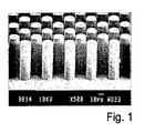
- Figure 1 shows a SEM microphotograph of an example of a micro fluidic structure embodying the inventive concept. It is evident from the picture that the micro posts have an identical shaped, a regular form and are evenly spaced over the support structure. Also the surface between the micro posts is even. A skilled person will recognize that the micro posts shown in the SEM microphotograph have a high aspect ratio. In this example, the micro posts were about 100 ⁇ m high, had a diameter of 20 ⁇ m and a center-to-center distance of 30 ⁇ m. This accounts for an aspect ratio of 1:5. It is generally held that an aspect ration > 1:2 is a high aspect ratio.
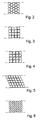
- Figures 2 through 6 show a number of different cross sections of the micro structures forming the fluid flow path according to the present invention.
- the micro structures or micro posts can have a cross section which is one of circular, elliptical, rhombic, triangular, square, rectangular, heptagonal, hexagonal etc or a combination thereof.
- the cross section can also be any fraction of the above forms, such as a half-circle, a crescent, U-shaped, X-shaped etc as long as the dimension and center-to-center distance of the individual microstructures is such, that capillary flow is induced without the provision of any lid or cover, limiting the flow path.
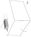
- Figure 7 shows schematically a flow path consisting of a multitude of circular micro posts 1 on a surface 2.
- the micro posts can naturally have any cross section, height and ceter-to-center distance, as long as the parameters are chosen such that capillary flow is induced.
- the direction of the capillary flow is indicated by the black arrow.
- the support 2 is schematically indicated as having a thickness comparable to the height of the micro posts. While this is not ruled out, the most frequently encountered supports will be considerably thicker.
- Figure 7 is thus only a schematic illustration.
- a device according to the invention may comprise a support and at least one flow path consisting of micro structures as shown in Figure 7 .
- a multitude of flow paths forming a channel system is required.
- the individual channels connect different functional regions, means or devices, such as reaction chambers, separation media etc.
- the basic structure embodying the inventive concept is a substrate having at least one flow path provided in or on its surface.
- This flow path or channel is formed by column like micro structures or micro posts, protruding from the surface of said surface.
- the characteristic feature of the flow path and the micro posts therein is that the dimensions of said posts and the distance between said posts are selected such that capillary flow of liquids can be maintained therein.
- the distance between said columns is in the range of 0.1 -1000 ⁇ m, preferably 1-100 ⁇ m.
- the columns are preferably higher than 1 ⁇ m, more preferably higher than 10 ⁇ m.
- Most preferably said micro posts have a high aspect ratio, that is a width to height ratio greater than 1:2.
- the micro posts can be either positioned within a secondary structure on the surface, such as a groove or a depressed area, or directly on the surface, protruding there from.
- a secondary structure such as a groove in a substrate
- the flow path will have a bottom located beneath the general substrate surface, and more or less vertical side walls, together with the bottom forming a channel. The capillary action inducing, the flow is however caused by the interaction between the liquid and the micro posts.
- the micro posts or columns are laid out as regions, preferably elongated, of upstanding columns, without any delimiting side walls.
- the flow path is subdivided into zones wherein the columns can have different column height, diameter, geometry and/or different column density, i.e. number of micro-posts per unit area.
- Figure 8 is a schematical illustration of this embodiment.
- a plurality of micro posts 1 are provided in close proximity in adjacent groups of micro posts having different size, shape or functionality.
- these groups are indicated 3, 4, and 5 and the differences shown as different size, shape and spacing only for the sake of illustration.
- Such groups can form an array, having desired functionality.
- Preferably said groups form a gradient, which can be continuous or discontinuous, preferably continuous.
- a first more dense zone 3 is provided, where the micro structures have a smaller diameter and smaller distance.
- Such zone can act as a sieve or "fence" preventing larger particles, e.g. cells from passing.
- a zone 4 with posts having relatively large spacing between them This can serve to temporarily decrease the time for a liquid-solid face interaction in a desired region, e.g. if it is desired that the sample be exposed to some surface bound moiety for an specified time, in order for a particular reaction to proceed to a reasonable completion etc.
- a zone 5 of larger micro posts squares in the shown example
- a second zone 4 similar to that is provided.
- the capillary flow path or paths has/have integrated surfaces or zones composed of bibulous material capable of capillary transport. This is schematically illustrated in Fig. 9 which shows a simple application of this concept.
- a closed channel structure not covered by the scope of the claims comprising a plurality of micro-posts 1 filling the channel.
- the structure has a bottom substrate 2 and a cover 6, the substrate also forming side walls (not shown), and having an input aperture or hole 7, an optional further aperture or hole 8, and an exit aperture (not shown). If a drop 9 of liquid is applied to the input aperture 7, a capillary flow will immediately begin, and will continue to draw liquid from the drop until the flow reaches the exit, where no further capillary action will occur. However, if a bibulous material such as pad 10 of filter paper or the like of sufficient size, is applied at, within or in contact with the exit aperture, this material will by its capability of drawing liquid act as a "flow sink", i.e. it will absorb the liquid that exits from the channel, thereby enabling an essentially continuous flow through the channel.
- a bibulous material such as pad 10 of filter paper or the like of sufficient size
- Another embodiment having a flow sink is that of the closed channel ending in an open region or zone of micro posts, said region having a relatively large area as compared to the channel.
- This large region will act as a flow sink in the same sense as the bibulous material discussed above. If e.g. heating means is provided to heat this region, evaporation of the liquid can be induced, thereby creating a sink that in principle could be maintained indefinitely. Evaporation of the liquid will also make possible the capture of components present in the flow, at a desired location and at a desired time in the device or process employing such device.
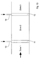
- Figure 10 shows schematically another embodiment and application of the flow path structures according to the invention, the flow path comprising a plurality of consecutive micro fluidic structures, interrupted by zones without such structures, i.e. a small space or discontinuity 11 and 12, said discontinuity acting as capillary barriers, preventing liquid from being transported across the zones without assistance.
- the direction of the liquid flow is illustrated with the large horizontal arrow.
- the discontinuities can be bridged or assisted transport can be brought about e.g. by applying a pressure pulse, whereby the capillary barriers provided by the voids are broken.
- the means for creating the pulse can be implemented by providing a very small channel 13 and 14 opening into the spacing, and for example momentarily applying sub-pressure (indicated with vertical arrows) in said channels. At the other end of the channel some means for providing a slight sub-pressure can be provided, whereby liquid from the regions on each side of the discontinuity will be forced into it, and when the gap is filled, capillary flow will again be resumed.
- Figure 11 shows a schematic partial view of a device according to the invention, where micro posts 1 are provided on a substrate 2, said substrate having larger protrusions 16 for carrying a cover or lid 15, said protrusions defining a distance between the surface the substrate and the lid considerably larger that the height of the micro posts, and such that no capillary interaction between the substrate and the lid can arise.
- the cover or lid 15 may further have apertures or holes 17, said holes preferably indication points for adding a sample or a reagent, for reading a result or for following the advancement of the reaction/reactions taking place on the substrate.
- the cover or lid is attached to the protrusions 16 only after the surface of the substrate has been functionalized or customized, i.e. after the addition of the necessary reagents and/or functionalities.
- Figure 12 shows schematically an exploded view of the embodiment of Figure 11 , where a pipette tip 18 is shown deposition of a drop of a liquid through an opening 17 on a flow path according to the invention.
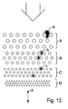
- Figure 13 illustrates an embodiment where groups of micro structures within a continuous flow path form a gradient with respect to at least one property, e.g. the shape, size, center-to-center distance or a functional / chemical property.
- the flow path comprises a discontinuos gradient with respect to the size and center-to-center distance of the micro structures, represented by the groups A, B, C and D.
- a gradient like this can function to delay the passage of biological or chemical entities, such as particles, cells, organelles, macro molecules or the like, in a desired manner, or separate such entities.
- Entities captured in zone A are illustrated by the shape "a", entities captured in zone B with "b” and so on.
- the shape "e” illustrates entities that pass unhindered through the gradient.
- the flow paths can comprise integrated surfaces or zones containing a number of different functional elements or devices for performing a number of different operations on the media located within or in association to the flow paths.
- functional elements or devices are electrodes and/or other means of electrical manipulation of liquids and reagents.
- the electrical manipulation can e.g. comprises oxidation/reduction of species.
- Other representative examples of functional devices are optics and other means to manipulate light e.g. for the purpose of measuring concentrations by absorbance, inducing conformational changes by light irradiation.
- Magnets or means for detection of magnetic substances can also be arranged in or around the flow paths. Thereby, magnetic particles can be trapped and retained at desired locations in the structure, and the magnetic property of the particles can thereby be used as a marker or indicator of successful transport to a certain point in the system. Furthermore, magnetic particles can be coated with substances with biological affinity and used in different kinds of assays.
- means for the manipulating of temperature can be provided in selected locations in a flow path according to the invention.
- means for the manipulating of temperature can be provided in selected locations in a flow path according to the invention.
- the particles within or in association to the flow paths, at least in one of the zones containing micro structures such as micro posts or columns, where there is subdivision between zones with and without these structures.
- the particles can thereby be bound by physical forces to said substrate, or chemically bound, e.g. covalently bound to said substrate.
- said particles can be mechanically trapped within the zone (zones) containing said structures.
- the substrate has reactive substances attached to its surface.
- reactive substances are used in connection with detection of substances of chemical or biological origin.
- the reactive substances are used in connection with immobilisation of substances of biological as well as non-biological origin, i.e. they are provided as sites to which the substances to be immobilized can react so as to become bound to the substrate.
- a reactive substance provided on the substrate is the use thereof in connection with separation of substances of biological as well as non-biological origin, where the substance can be selectively reactive with a species that one wishes to separate from another in a mixture.
- the surfaces of a channel in a structure according to the invention can be modified by chemical or physical means. Such a modified surface can thereby be used in connection with detection of substances of biological and chemical origin.
- a modified surface of this kind can be used in connection with immobilisation of substances of biological as well as non-biological origin. It can also be used in connection with separation of substances of biological as well as non-biological origin.
- flow paths are used as means for multi spot detection, whereby said paths optionally have particles provided therein, said particles having chemically reactive groups or substances with bio-affinity bound in the micro spot area.
- flow path structures are suitable applications of flow path structures according to the invention.
- a biological sample e.g. in blood, serum, plasma, urine, cerebral spinal fluid, tears, amniotic fluid, semen or saliva, the measurements preferably being based on specific biological interactions.
- a specific application is that said analyte is measured by immunological means.
- the analyte can also be detected by specific interactions using poly or oligonucleotides, preferably single stranded nucleic acids or aptameres.
- the flow path structures according to the invention can also be used for the separation of cells, and for the screening of synthetic or biological libraries.
- a channel for the purposes of the present invention goes beyond the ordinary concept of a channel, by allowing entirely open structures having no physical delimitations except for a bottom substrate on which the micro post or column structures are provided.
- the channel or flow path comprises a groove (i.e. having a bottom and side walls), there is the option to leave the channel open upwards.
- micro-fluidic structure may be very sensitive to oxygen, and therefore it may be absolutely necessary to exclude the sample liquid from atmospheric exposure.
- access openings in said cover for enabling introduction of e.g. reagents, gas, liquids, or samples into said structure.
- Such access openings can also be used for connecting external equipment, e.g. via suitable tubing or the like.
- Manufacturing of such microstructures could in its simplest form be done by direct curing of a photosensitive mono- or pre-polymer deposited on a substrate, employing a mask through which light is irradiated to initiate curing, and thereafter rinsing away the un-cured areas (thick film photo-resist process).
- An other straightforward method is through replication of an original into a polymer.
- the original could be manufactured in silicon through a DRIE-process (Deap Reactive Ion Etch) where high aspect ration structures could be produced.
- DRIE-process Deap Reactive Ion Etch
- Other ways of producing such originals could for instance be through laser processing, electro discharge methods, Free Form Manufacturing (FFM), electrochemical or chemical etching, gas phase etching, mechanical processing, thick film photoresist processes or combinations thereof, of or on a substrate of, for instance, silicon, glass, quartz, ceramic, metal or plastic material. e.g. PMMA or Teflon.
- the most straight forward method of replication would be casting of a mono- or pre-polymer over an original with the desired negative shape.
- Other ways of producing the polymer replicas could involve injection molding or embossing of thermoplastics or thermoset materials.
- a an intermediate replica in a suitable material could first be produced from the original.
- stamper process could be to first deposit a conducting layer on top of the original and thereafter through electroplating form a negative from the original.
- Certain plating materials such as Nickel lend themselves also to the repeated and non-destructive production of copies of the stamper. This gives the possibility to both change polarity from negative to positive as well as producing series of identical stampers for large volume production of replicas.
- Other examples of stamper manufacturing could be in a well chosen polymer given the negative shape of the original in a casting, embossing or injection molding process. The same possibility of repeatedly and non-destructively making copies of the stamper could also be true for polymer stampers.
- micro-fluidic structure of the invention may, of course, be designed for a plurality of micro-fluidic purposes. Among those are e.g. capillary chromatography, ion-exchange chromatography, hydrophobic interaction chromatography, immunoassays, hybridization assays and other molecular biology assays, micro reaction cavity procedures, miniaturized liquid communication units, biosensor flow cells, etc.
- Reaction cavities constructed in accordance with the invention may, for example, be used for various forms of solid phase synthesis, such as peptide or oligonucleotide synthesis. PCR, DNA solid phase sequencing reactions, sample treatment and detection, just to mention a few.
- micro fluidic structures according to the invention can be made in different ways. One convenient method is outlined above, but it is also possible to make the structures from separate parts which are assembled after column formation has taken place in a suitable substrate.
- Example 1 Flow in open channels with columns made of silicon
- Flow channels were produced by etching silicon wafers by a standard method well known to a person skilled in the art.
- the resulting silicon chips had a length of 25 mm and a width of 5 mm.
- the area covered by columns was 10 mm long and 4 mm wide.
- the columns had a height of 100 ⁇ m and a diameter of 20 ⁇ m, the center-to-center distance being 30 ⁇ m.
- Capillary flow was tested with purified water, buffer and blood plasma.
- a wicking membrane (Whatman WF 1.5) was placed a few mm in at the distal end of the chip to facilitate the liquid flow.
- Example 2 Flow in open channels with columns made of epoxy plastic
- Flow channels were produced by first etching silicon wafers by a standard method well known to a person skilled in the art. A thin layer of epoxy was the applied uniformly to the silicon wafer. The resulting epoxy covered chips had a length of 25 mm and a width of 5 mm. The area covered by columns was 10 mm long and 4 mm wide. The columns had a height of approximately 90 ⁇ m and a diameter of approximately 20 ⁇ m, the center-to-center distance being close to 30 ⁇ m.
- Capillary flow was tested with purified water and buffer.
- a wicking membrane (Whatman WF 1.5) was placed a few mm in at the distal end of the chip to facilitate the liquid flow.
- the chip was pretreated (one hour, room temperature) with a buffer containing 50 mmole/l sodium phosphate, 6% bovine serum albumin, 0,2% Tween 20, pH 7.5 prior to addition of water or buffer. 8 ⁇ l of water added to zone 1 took about 90 seconds to flow through the zone with columns. Similar flow speed was found with a buffer containing 50 mmole/l sodium phosphate, 6% bovine serum albumin, 0,2% Tween 20, pH 7.5.
Abstract
Description
- The present invention relates to micro fluidic structures, and in particular to a micro structure defining a liquid flow system, wherein capillary action is utilized as the main driving force for liquid transport through said structure.
- The micro fluidic structure according to the invention is useful in various fields of application such as miniaturized bioassays, preparatory steps for such assays, separation, electrophoresis, capillary chromatography, micro reaction cavity procedures, miniaturized liquid communication units, biosensor flow cells and the like.
- Liquid transport through channels or structures on a micro scale has important implications in a number of different technologies.
- Controlled transport of fluids through micro channels has been a challenge, with the microstructure itself imparting difficulties not found on a larger scale. The driving force utilized in most micro channel structures depends on electro-endosmosis, gravitational forces, external pressure or capillary migration.
- Surface materials often have unbound electrons, polar moieties, or other features generating a surface charge or reactivity. Surface characteristics often have a more pronounced impact on a micro scale system than on a larger structure. This is particularly true in micro systems where the fluid flow is driven by attractions between liquids and the surface materials through which they are transported.
- In a closed capillary the driving force is usually represented by the equation:

where h = the height of a fluid within a capillary tube; θc = the contact angle of the fluid with the capillary tube material. - If the contact angle of the capillary tube material, with respect to the fluid, is less than 90°, the material is considered hydrophilic. If the contact angle of the tube material, with respect to the fluid, is greater than 90°, the material is considered hydrophobic. σgl represents the surface tension of the fluid with respect to the air (millijoules/m2), g is the gravitational constant (m/s2), r is the radius of the capillary tube (m), and ρ is the fluid density (kg/n3).
- Planar micro structures have been developed in which a number of grooves or channels are made, typically such a planar structure is produced by etching grooves in a semiconductor substrate, such as a silicon wafer, and then covering the etched surface by a cover plate to complete the channels. Such structures are, however, rather time consuming and expensive to produce.
- Further, when such structures need to be customized, e.g. by the addition of chemical reagents, the functionalization of surfaces etc., these steps often need to be performed by somebody other than the producer of the micro structure. In practice, the micro structures are manufactured at one location and shipped to another facility e.g. for the addition of reagents, whereupon they often need to be returned to the manufacturer for closing and sealing. One aim of the present invention is therefore to make available a micro structure offering greater flexibility and ease, in particular with regard to the post-production customization.
- Systems used at present utilize external means, e.g. gravity, centrifugal force (spinning of disk elements with micro channels on the surface), or pressure to impose transport of liquids in channels. Also electric fields can be used to impose transport of dissolved charged species in micro systems. To this end, external auxiliary equipment is employed, such as a motor to generate the spinning of a disk, pumps to create pressure, electrodes and power supplies to apply electric fields etc. Such equipment is costly and sometimes rather complex. Furthermore, in certain cases the forces involved in the above mentioned methods could have detrimental effects on sensitive substances. Another aim of the invention is therefore to make available a micro structure with built-in functionality, removing or reducing the need of external means to impose liquid transport.
-
EP 1 120 164 describes the use of a plurality of micro structures in a capillary pathway, said pathway having at least one curved portion, the pathway comprising a base, an inner wall defined by a first radius from a center point and defined by a second radius greater than the first radius, the inner wall and outer wall being fixed to the base and defining the lateral boundaries of the capillary pathway, and a lid extending at least from the inner wall to the outer wall covering the capillary pathway. It becomes clear that the micro structures themselves do not form a capillary pathway, but only influence the flow as the fluid travels around curved portions in said capillary pathway, the flow being somewhat slower near the inner wall of a curved portion than near the outer wall. -
U.S. 5,885,527 , cited in theabove EP 1 120 164 describes assay devices including micro structures forming reaction barriers. These reaction barriers are formed by corrugated or otherwise patterned surfaces, having grooves which together with a cover or top member form narrow channels between different chambers in said device. It is clear from the description and figures, that the capillary channels are indeed formed only when a top member is placed on a bottom member a capillary distance apart. Further, the top and bottom members may be married, the various chambers sealed and the capillaries formed by a number of techniques, including but not limited to, gluing, welding by ultrasound, riveting and the like. -
U.S. 5,837,115 discloses a sorting apparatus and method for fractionating and simultaneously viewing individual micro structures, such as cells, viruses, macro molecules or minute particles in a fluid medium. The aim of the invention is to replace agarose gels and other traditionally used fractionation media with a lattice structure with uniform distribution, size and shape of the hindered environment. The hindered environment may be formed by posts, bunkers, v-shaped or cup-shaped structures, forming sifting means for the cells, viruses etc under study. This structure is covered by ceiling means positioned over the lattice causing the migration of microstructures in essentially a single layer through the sifting means exclusively. The invention according toU.S. 5,837,115 does not seem to consider capillary forces, but instead suggests the provision of electrodes for generating an electric field over the lattice structure. - It is widely known to use channels filled with porous material, as exemplified in
U.S. 5,540,888 , said porous material having sub-channels divided by slots, liquid impermeable separating portions etc., and containing reagent regions and sample application regions. Filter paper is often the material of choice, and there exists a wide range of technologies for applying reagents to this material. - It remains to make available micro fluidic structures integrated in a support which is suitable for mass production, and in a configuration which makes the micro fluidic device, comprising said structures, easily handled in the down-stream production process, and in particular in the customization of the device.
- In view of the drawbacks of having to use relatively complex external equipment for influencing liquid flow, which in addition could damage the samples, it would be both desirable and advantageous to enable "automatic" transport of sensitive substances without use of complex devices and without subjecting the substances to the risk of being altered, e.g. denaturated or otherwise damaged.
- One aim of the present invention is therefore to provide a micro-fluidic structure, i.e. a geometric micro structure defining a liquid flow system, suitable for capillary transport of liquids and which is inexpensive to produce, optionally permitting a disposable type product, optionally having branched flow channels, optionally exhibiting local surface characteristics, and providing great freedom in choice of material, e.g. with regard to surface, optical and electric properties.
- Further aims underlying the invention, as well as the advantages associated with the inventive solution and its embodiments, will become apparent from the following description and examples, together with the attached claims and drawings.
- The above aims are achieved with the present invention by employing the phenomenon of capillary action to drive liquid flow through open micro structures provided on solid substrates. In its widest scope, the micro fluidic structure according to the present invention comprises various forms of geometric micro structures defining the desired liquid flow system.
- The present invention in its broadest aspect provides a flow path consisting of a multitude of micro structures inducing the flow of fluids through said flow path, as well as methods where this flow path is used.
- The invention in particular provides a micro fluidic system comprising a substrate, and, provided on said substrate, at least one flow path and functional means in which liquid samples can be treated by desired procedures, wherein said at least one flow path is/are laid out to form a pattern for the transport of liquid samples to, through and from said functional means; wherein the flow path consists of a plurality of micro posts protruding upwards from said substrate; wherein the spacing between the micro posts is such as to induce a capillary action in a liquid sample applied anywhere to said flow path, so as to force said liquid to move from where said liquid sample was applied.
- The present invention will be described in closer detail in the following description and non-limiting examples, with reference to the attached claims and drawings, in which:
-
Figure 1 is a SEM microphotograph of a portion of a structure according to the invention; -
Figures 2 through 6 show cross sections of the capillary structure according different embodiments of the present invention; -
Figure 7 shows a perspective view of one embodiment of a flow path where the capillary structure is formed of micro posts having a circular cross section; with no walls nor cover which would significantly contribute to the capillary action, according to the present invention; -
Figure 8 illustrates one embodiment of a flow path according to the present invention comprising zones with capillary structures or micro posts having different cross sections and different dimensions in adjacent zones; -
Figure 9 shows schematically in cross section perpendicular to the plane of the device, the use of a bibulous material for maintaining or enhancing flow in a flow path according to the present invention; -
Figure 10 shows schematically how a flow path according to the present invention can be divided into zones, separated by "barriers" preventing the capillary flow, and means for resuming or re-starting the flow; -
Figure 11 shows schematically a cross section of a device having micro structures forming a flow path on a surface, and a separate lid, not significantly contributing to the capillary flow. -
Figure 12 shows schematically a partial exploded view of a device according to the invention, and as illustrated inFig. 11 , where a drop of liquid, e.g. a sample, is being added with a pipette through a hole in said separate lid; and -
Figure 13 shows schematically an embodiment where micro post of different size and/or functionality form a discontinuous gradient. - Before the present invention is described, it is to be understood that the terminology employed herein is used for the purpose of describing particular embodiments only and is not intended to be limiting, since the scope of the present invention will be limited only by the appended claims and equivalents thereof.
- The prefix "micro" as in micro fluidic, micro structure etc is used to define a device or a process which comprises or involves at least one feature having a leght, width or height normally expressed in micrometers (µm, 1 x 10⁻⁶ m).
- The prefix "nano" is here used in its generally accepted meaning, as in nanometer (nm, 1 x 10⁻⁹ m).
- The expression "passive" as used in e.g. "passive control" or "passive fluid dynamics" refers for the purposes of this invention to a control that is not influenced by actions taken during a process that is to be carried out, but rather the control is determined by fixed system parameters, which are design dependent. The passive control is generated by using the natural capillary forces that exist on a micro scale.
- The term "open" in this context means that the flow paths defined by the micro structures are accessible from above and have no cover or lid which takes part in creating the capillary flow. The above definition does however not rule out that a secondary cover or lid, at a distance from the micro structure, can be provided.
- The term "hydrophilic groups" refers to substrates and substances having polar and/or charged groups, such as hydroxyl, carboxyl, amino, sulphonate, thiol, aldehyde etc.
- The term "hydrophobic structure" refers to substrates and substances having non polar structures.
- The term "chemically reactive groups" refers to all organic and inorganic groups used in covalent coupling of molecules to solid faces and known to persons skilled in the art, such a hydroxyl, carboxyl, amino, sulphonate, thiol, aldehyde etc.
- The term "biological affinity" refers to substances having specific binding of a substance or a defined group of related substances. Exemplary substances are antibodies, antigens, haptens, biotin, avidin, lectin, sugar, nucleic acids, hormones and their receptors.
- The invention in its broadest aspect provides a multi-element capillary structure adapted to effect the capillary flow of liquids along said structure in open systems by using micro-structures provided on or in said structure. Advantage is taken of the surface effects between a fluid and the surfaces contacting the fluid. These surface effects come into play at the micro scale.
- In particular there is provided devices having a structure comprising at least one liquid flow path, connecting different processing compartments within said structure for carrying out a number of different unit operations. Examples of such processing compartments, elements and/or devices are chemical reaction compartments, incubation compartments, wash compartments or elements, flow control elements, measurement elements, time gates, separation means, heating means, means for irradiation with electromagnetic radiation, magnetic means for trapping magnetic components of said liquid within said functional means, electrodes for applying voltage to the liquid over a selected region, detectors for detecting physical or chemical properties e.g, temperature, pH, viscosity, absorbance etc., or any other device or means for chemically, biologically or physically treating a liquid sample or reaction mixture located within or passing through said compartment, element and/or device.
- In order to clarify the principle behind the inventive concept the following illustration is given:
- Consider a simple example of the effect of surface forces, such as demonstrated when water is drawn into an glass capillary without any outside pressure being applied. This is caused by the surface tension between the water and the glass surface, which pulls water into the capillary. The narrower the capillary, the greater the effect of the force that pulls the water into the capillary. This is often referred to as the capillary force.
- One physical parameter that characterizes the magnitude of the capillary force is the contact angle between the water and the surrounding material. For contact angles less than 90°, the material, e.g., glass, is considered to be hydrophilic and water is drawn up into the capillary space. When the material has a contact angle greater than 90° it is considered hydrophobic. In the hydrophobic case, pressure is required to force water into the space. The narrower the capillary, the greater the force that is required. However, in both cases once water has been introduced into the capillary, the flow rates of the water depend more on pressure gradients and friction and less on whether the material is hydrophobic or hydrophilic.
- In order to achieve the desired function of the micro structures forming the flow paths of the present invention, the contact area between liquid and the surface of the solid material is maximized, whereby the capillary force increases so that a fluid flow within or along the flow path according to the invention is spontaneously induced and maintained over a desired period of time.
- This process represents what can be referred to as "passive fluid dynamics". The present inventors have found that it is advantageous to use such passive fluid dynamics to control and drive the flow of fluid in open micro channels or structures on a surface. For example, the passive nature of the transport mechanism according to the invention makes it direction independent, as compared to a system on a spinning disk where mainly a radial transport is possible. Transport by application of an electric field is mainly bi-directional at best. Capillary flow can be induced in any direction, provided the pattern of micro structures forming the flow paths is designed properly. A person skilled in the field of desingning micro structures and fluid flow cannerls on such structures will be able to apply the teaching of the invention without undue experimentation.
-
Figure 1 shows a SEM microphotograph of an example of a micro fluidic structure embodying the inventive concept. It is evident from the picture that the micro posts have an identical shaped, a regular form and are evenly spaced over the support structure. Also the surface between the micro posts is even. A skilled person will recognize that the micro posts shown in the SEM microphotograph have a high aspect ratio. In this example, the micro posts were about 100 µm high, had a diameter of 20 µm and a center-to-center distance of 30 µm. This accounts for an aspect ratio of 1:5. It is generally held that an aspect ration > 1:2 is a high aspect ratio. -
Figures 2 through 6 show a number of different cross sections of the micro structures forming the fluid flow path according to the present invention. The micro structures or micro posts can have a cross section which is one of circular, elliptical, rhombic, triangular, square, rectangular, heptagonal, hexagonal etc or a combination thereof. The cross section can also be any fraction of the above forms, such as a half-circle, a crescent, U-shaped, X-shaped etc as long as the dimension and center-to-center distance of the individual microstructures is such, that capillary flow is induced without the provision of any lid or cover, limiting the flow path. -
Figure 7 shows schematically a flow path consisting of a multitude of circularmicro posts 1 on asurface 2. The micro posts can naturally have any cross section, height and ceter-to-center distance, as long as the parameters are chosen such that capillary flow is induced. The direction of the capillary flow is indicated by the black arrow. InFig. 7 , thesupport 2 is schematically indicated as having a thickness comparable to the height of the micro posts. While this is not ruled out, the most frequently encountered supports will be considerably thicker.Figure 7 is thus only a schematic illustration. - A device according to the invention may comprise a support and at least one flow path consisting of micro structures as shown in
Figure 7 . However, for most practical applications, a multitude of flow paths forming a channel system is required. The individual channels connect different functional regions, means or devices, such as reaction chambers, separation media etc. - When the properties of the columns and their properties, such as their material, their shape and/or distance, and optionally also the properties of the substrate, are selected properly with due consideration taken to the liquid to be transported, it will become possible to create a capillary flow through said structure, in the direction of the arrow if a liquid sample is place at the end where the arrow points, without any significant leakage out from the structure and onto the surrounding substrate surface.
- Thus, the basic structure embodying the inventive concept is a substrate having at least one flow path provided in or on its surface. This flow path or channel is formed by column like micro structures or micro posts, protruding from the surface of said surface. The characteristic feature of the flow path and the micro posts therein is that the dimensions of said posts and the distance between said posts are selected such that capillary flow of liquids can be maintained therein. In particular, the distance between said columns is in the range of 0.1 -1000 µm, preferably 1-100 µm. The columns are preferably higher than 1 µm, more preferably higher than 10 µm. Most preferably said micro posts have a high aspect ratio, that is a width to height ratio greater than 1:2.
- It is understood that the micro posts can be either positioned within a secondary structure on the surface, such as a groove or a depressed area, or directly on the surface, protruding there from. When the micro posts are in a secondary structure, such as a groove in a substrate, the flow path will have a bottom located beneath the general substrate surface, and more or less vertical side walls, together with the bottom forming a channel. The capillary action inducing, the flow is however caused by the interaction between the liquid and the micro posts.
- However, according to a preferred embodiment, the micro posts or columns are laid out as regions, preferably elongated, of upstanding columns, without any delimiting side walls.
- According to a further embodiment of the present invention, the flow path is subdivided into zones wherein the columns can have different column height, diameter, geometry and/or different column density, i.e. number of micro-posts per unit area.
Figure 8 is a schematical illustration of this embodiment. A plurality ofmicro posts 1 are provided in close proximity in adjacent groups of micro posts having different size, shape or functionality. InFigure 8 , these groups are indicated 3, 4, and 5 and the differences shown as different size, shape and spacing only for the sake of illustration. Such groups can form an array, having desired functionality. Preferably said groups form a gradient, which can be continuous or discontinuous, preferably continuous. - In the embodiment shown in
Figure 8 , a first moredense zone 3 is provided, where the micro structures have a smaller diameter and smaller distance. Such zone can act as a sieve or "fence" preventing larger particles, e.g. cells from passing. Next, there is a zone 4 with posts having relatively large spacing between them. This can serve to temporarily decrease the time for a liquid-solid face interaction in a desired region, e.g. if it is desired that the sample be exposed to some surface bound moiety for an specified time, in order for a particular reaction to proceed to a reasonable completion etc. After this low velocity region there is provided a zone 5 of larger micro posts (squares in the shown example) having fairly narrow passages between them. After this region, a second zone 4 similar to that is provided. Based on the information given in this description and the examples, a skilled person can design various combinations, according to the desired purpose. - According to another embodiment of the invention, the capillary flow path or paths has/have integrated surfaces or zones composed of bibulous material capable of capillary transport. This is schematically illustrated in
Fig. 9 which shows a simple application of this concept. - In this case there is a closed channel structure not covered by the scope of the claims comprising a plurality of
micro-posts 1 filling the channel. The structure has abottom substrate 2 and acover 6, the substrate also forming side walls (not shown), and having an input aperture orhole 7, an optional further aperture orhole 8, and an exit aperture (not shown). If adrop 9 of liquid is applied to theinput aperture 7, a capillary flow will immediately begin, and will continue to draw liquid from the drop until the flow reaches the exit, where no further capillary action will occur. However, if a bibulous material such aspad 10 of filter paper or the like of sufficient size, is applied at, within or in contact with the exit aperture, this material will by its capability of drawing liquid act as a "flow sink", i.e. it will absorb the liquid that exits from the channel, thereby enabling an essentially continuous flow through the channel. - Another embodiment having a flow sink, is that of the closed channel ending in an open region or zone of micro posts, said region having a relatively large area as compared to the channel. This large region will act as a flow sink in the same sense as the bibulous material discussed above. If e.g. heating means is provided to heat this region, evaporation of the liquid can be induced, thereby creating a sink that in principle could be maintained indefinitely. Evaporation of the liquid will also make possible the capture of components present in the flow, at a desired location and at a desired time in the device or process employing such device.
-
Figure 10 shows schematically another embodiment and application of the flow path structures according to the invention, the flow path comprising a plurality of consecutive micro fluidic structures, interrupted by zones without such structures, i.e. a small space ordiscontinuity - The discontinuities can be bridged or assisted transport can be brought about e.g. by applying a pressure pulse, whereby the capillary barriers provided by the voids are broken. The means for creating the pulse can be implemented by providing a very
small channel -
Figure 11 shows a schematic partial view of a device according to the invention, wheremicro posts 1 are provided on asubstrate 2, said substrate havinglarger protrusions 16 for carrying a cover orlid 15, said protrusions defining a distance between the surface the substrate and the lid considerably larger that the height of the micro posts, and such that no capillary interaction between the substrate and the lid can arise. The same applies to an alternative embodiment where the micro posts are located in grooves or depressions in the surface. The cover orlid 15 may further have apertures or holes 17, said holes preferably indication points for adding a sample or a reagent, for reading a result or for following the advancement of the reaction/reactions taking place on the substrate. - According to a preferred embodiment, the cover or lid is attached to the
protrusions 16 only after the surface of the substrate has been functionalized or customized, i.e. after the addition of the necessary reagents and/or functionalities. -
Figure 12 shows schematically an exploded view of the embodiment ofFigure 11 , where apipette tip 18 is shown deposition of a drop of a liquid through anopening 17 on a flow path according to the invention. -
Figure 13 illustrates an embodiment where groups of micro structures within a continuous flow path form a gradient with respect to at least one property, e.g. the shape, size, center-to-center distance or a functional / chemical property. In the figure, the flow path comprises a discontinuos gradient with respect to the size and center-to-center distance of the micro structures, represented by the groups A, B, C and D. A gradient like this can function to delay the passage of biological or chemical entities, such as particles, cells, organelles, macro molecules or the like, in a desired manner, or separate such entities. Entities captured in zone A are illustrated by the shape "a", entities captured in zone B with "b" and so on. The shape "e" illustrates entities that pass unhindered through the gradient. - In further embodiments, the flow paths can comprise integrated surfaces or zones containing a number of different functional elements or devices for performing a number of different operations on the media located within or in association to the flow paths. Examples of such functional elements or devices are electrodes and/or other means of electrical manipulation of liquids and reagents. The electrical manipulation can e.g. comprises oxidation/reduction of species. Other representative examples of functional devices are optics and other means to manipulate light e.g. for the purpose of measuring concentrations by absorbance, inducing conformational changes by light irradiation.
- Magnets or means for detection of magnetic substances can also be arranged in or around the flow paths. Thereby, magnetic particles can be trapped and retained at desired locations in the structure, and the magnetic property of the particles can thereby be used as a marker or indicator of successful transport to a certain point in the system. Furthermore, magnetic particles can be coated with substances with biological affinity and used in different kinds of assays.
- Furthermore, means for the manipulating of temperature can be provided in selected locations in a flow path according to the invention. Thereby a number of interesting functions can be performed such as, chemical reactions, incubation, thermal curing, PCR reactions, evaporations, drying etc.
- Within the flow path structures according to the invention there can be provided particles within or in association to the flow paths, at least in one of the zones containing micro structures such as micro posts or columns, where there is subdivision between zones with and without these structures. The particles can thereby be bound by physical forces to said substrate, or chemically bound, e.g. covalently bound to said substrate. Alternatively, said particles can be mechanically trapped within the zone (zones) containing said structures.
- According to a preferred embodiment, the substrate has reactive substances attached to its surface. Such reactive substances are used in connection with detection of substances of chemical or biological origin. The reactive substances are used in connection with immobilisation of substances of biological as well as non-biological origin, i.e. they are provided as sites to which the substances to be immobilized can react so as to become bound to the substrate.
- Another application of a reactive substance provided on the substrate is the use thereof in connection with separation of substances of biological as well as non-biological origin, where the substance can be selectively reactive with a species that one wishes to separate from another in a mixture.
- The surfaces of a channel in a structure according to the invention can be modified by chemical or physical means. Such a modified surface can thereby be used in connection with detection of substances of biological and chemical origin. A modified surface of this kind can be used in connection with immobilisation of substances of biological as well as non-biological origin. It can also be used in connection with separation of substances of biological as well as non-biological origin.
- Still another application of the flow path or channel structure according to the invention, is that the flow paths are used as means for multi spot detection, whereby said paths optionally have particles provided therein, said particles having chemically reactive groups or substances with bio-affinity bound in the micro spot area.
- Other suitable applications of flow path structures according to the invention is the measurements of the amount of an analyte in a biological sample, e.g. in blood, serum, plasma, urine, cerebral spinal fluid, tears, amniotic fluid, semen or saliva, the measurements preferably being based on specific biological interactions.
- A specific application is that said analyte is measured by immunological means.
- The analyte can also be detected by specific interactions using poly or oligonucleotides, preferably single stranded nucleic acids or aptameres.
- The flow path structures according to the invention can also be used for the separation of cells, and for the screening of synthetic or biological libraries.
- As discussed above, the notion of a "channel" for the purposes of the present invention goes beyond the ordinary concept of a channel, by allowing entirely open structures having no physical delimitations except for a bottom substrate on which the micro post or column structures are provided.
- However, when the channel or flow path comprises a groove (i.e. having a bottom and side walls), there is the option to leave the channel open upwards.
- In cases where it is desirable to manipulate the liquid that is transported and/or the substances transported by said liquid, it may sometimes be more convenient to have unrestricted access from above, such as for the purpose of adding reagents at desired points in the structure, to apply direct heat, or to perform other manipulations at more or less arbitrarily points.
- Certain systems may be very sensitive to oxygen, and therefore it may be absolutely necessary to exclude the sample liquid from atmospheric exposure. If the micro-fluidic structure is covered, there can be provided access openings in said cover for enabling introduction of e.g. reagents, gas, liquids, or samples into said structure. Such access openings can also be used for connecting external equipment, e.g. via suitable tubing or the like.
- Manufacturing of such microstructures could in its simplest form be done by direct curing of a photosensitive mono- or pre-polymer deposited on a substrate, employing a mask through which light is irradiated to initiate curing, and thereafter rinsing away the un-cured areas (thick film photo-resist process).
- An other straightforward method is through replication of an original into a polymer. The original could be manufactured in silicon through a DRIE-process (Deap Reactive Ion Etch) where high aspect ration structures could be produced. Other ways of producing such originals could for instance be through laser processing, electro discharge methods, Free Form Manufacturing (FFM), electrochemical or chemical etching, gas phase etching, mechanical processing, thick film photoresist processes or combinations thereof, of or on a substrate of, for instance, silicon, glass, quartz, ceramic, metal or plastic material. e.g. PMMA or Teflon.
- The most straight forward method of replication would be casting of a mono- or pre-polymer over an original with the desired negative shape. Other ways of producing the polymer replicas could involve injection molding or embossing of thermoplastics or thermoset materials.
- If the original in some aspects are not withstanding the replication process a an intermediate replica in a suitable material (a stamper) could first be produced from the original. Examples of such stamper process could be to first deposit a conducting layer on top of the original and thereafter through electroplating form a negative from the original. Certain plating materials such as Nickel lend themselves also to the repeated and non-destructive production of copies of the stamper. This gives the possibility to both change polarity from negative to positive as well as producing series of identical stampers for large volume production of replicas. Other examples of stamper manufacturing could be in a well chosen polymer given the negative shape of the original in a casting, embossing or injection molding process. The same possibility of repeatedly and non-destructively making copies of the stamper could also be true for polymer stampers.
- As mentioned above the micro-fluidic structure of the invention may, of course, be designed for a plurality of micro-fluidic purposes. Among those are e.g. capillary chromatography, ion-exchange chromatography, hydrophobic interaction chromatography, immunoassays, hybridization assays and other molecular biology assays, micro reaction cavity procedures, miniaturized liquid communication units, biosensor flow cells, etc. Reaction cavities constructed in accordance with the invention may, for example, be used for various forms of solid phase synthesis, such as peptide or oligonucleotide synthesis. PCR, DNA solid phase sequencing reactions, sample treatment and detection, just to mention a few.
- The micro fluidic structures according to the invention can be made in different ways. One convenient method is outlined above, but it is also possible to make the structures from separate parts which are assembled after column formation has taken place in a suitable substrate.
- In the following, the invention will be illustrated by specific non-limiting examples.
- Flow channels were produced by etching silicon wafers by a standard method well known to a person skilled in the art. The resulting silicon chips had a length of 25 mm and a width of 5 mm. The area covered by columns was 10 mm long and 4 mm wide. The columns had a height of 100 µm and a diameter of 20 µm, the center-to-center distance being 30 µm.
- Capillary flow was tested with purified water, buffer and blood plasma. A wicking membrane (Whatman WF 1.5) was placed a few mm in at the distal end of the chip to facilitate the liquid flow.
- 8 µl of water added to the structure took between 60 and 90 seconds to flow across the structure provided with columns. A similar flow speed was measured with a buffer containing 50 mmole/l sodium phosphate, 6 % bovine serum albumin, 0,2 % Tween 20, pH 7.5. Blood plasma was slightly faster than water and buffer.
- Flow channels were produced by first etching silicon wafers by a standard method well known to a person skilled in the art. A thin layer of epoxy was the applied uniformly to the silicon wafer. The resulting epoxy covered chips had a length of 25 mm and a width of 5 mm. The area covered by columns was 10 mm long and 4 mm wide. The columns had a height of approximately 90 µm and a diameter of approximately 20 µm, the center-to-center distance being close to 30 µm.
- Capillary flow was tested with purified water and buffer. A wicking membrane (Whatman WF 1.5) was placed a few mm in at the distal end of the chip to facilitate the liquid flow. The chip was pretreated (one hour, room temperature) with a buffer containing 50 mmole/l sodium phosphate, 6% bovine serum albumin, 0,2% Tween 20, pH 7.5 prior to addition of water or buffer. 8 µl of water added to
zone 1 took about 90 seconds to flow through the zone with columns. Similar flow speed was found with a buffer containing 50 mmole/l sodium phosphate, 6% bovine serum albumin, 0,2% Tween 20, pH 7.5. - The above examples demonstrate that it is possible to create open flow paths consisting of micro structures and that these function, i.e. that the necessary capillary forces are created and that liquid transport takes place.
Claims (28)
- A micro fluidic system comprising a substrate (2), and, provided on said substrate, at least one flow path and processing compartments in which liquid samples can be treated by desired procedures, wherein said at least one flow path is/are laid out to form a pattern for the transport of liquid samples to, through and from said processing compartments; characterized in that the flow path is open and has no cover or lid which takes part in creating capillary flow and consists of a plurality of micro posts (1) protruding upwards from said substrate; wherein the spacing between the micro posts is such as to induce a capillary action in a liquid sample applied anywhere to said flow path, so as to force said liquid to move from where said liquid sample was applied.
- The micro fluidic system according to claim 1, wherein the processing compartments comprise one or more of chemical reactors, separation means, heating means, means for irradiation with electromagnetic radiation, magnetic means for trapping magnetic components of said liquid within said processing compartments and electrodes for applying voltage to the liquid over a selected region.
- The micro fluidic system according to claim 1 or 2, wherein said substrate (2) is provided with grooves having a bottom surface and side walls, and wherein the flow paths consist of micro posts (1) protruding from the bottom surface of said grooves.
- The micro fluidic system according to claim 3, wherein said flow paths are covered by a top or lid (15), said top or lid not contributing to the capillary action in said flow channel.
- The micro fluidic system according to claim 4, wherein the lid (15) has access openings for enabling introduction of reagents, gas, liquids, samples into said flow paths.
- The micro fluidic system according to claim 1 or 2, wherein the substrate (2) is essentially flat and the micro posts (1) protrude from said substrate.
- The micro-fluidic system according to any one of the preceding claims, wherein the micro posts are grouped in adjacent segments so as to provide a spacing or discontinuity between such segments, the discontinuity having a finite distance, which is large enough to prevent capillary flow between said segments, thereby providing a flow stop.
- The micro fluidic system according to claim 7, wherein there are provided means for applying energy to one or more selected segments so as to induce a forced transport across the flow stop.
- The micro fluidic system according to claim 8, wherein said energy applying means is selected from a pressure pulse generator, an ultrasound generator, an electromagnetic radiation means.
- The micro fluidic system according to claim 7, comprising means for applying liquid to said discontinuity in order to provide a bridge across said discontinuity so as to induce a flow there across.
- The micro fluidic system according to claim 1, wherein the micro posts have a functionality in the form of chemically reactive groups on their surface.
- The micro fluidic system according to claim 1, wherein the micro posts have a functionality in the form of substances with biological affinity bound to their surface.
- The micro fluidic system according to claim 1, wherein the micro posts have a functionality in the form of hydrophilic groups on their surface.
- The micro fluidic system according to claim 1, wherein the micro posts have a functionality in the form of positively and/or negatively charged groups on their surface.
- The micro fluidic system according to claim 1, wherein the micro posts have a functionality in the form of hydrophobic structures on their surface.
- The micro fluidic system according to any of the claims 11-15, wherein said functionality is applied to the micro posts in the entire flow paths or limited to a discrete region or portion of the flow path.
- The micro fluidic system according to claim 1, wherein the micro posts have properties selected from the micro post diameter, height, shape, cross section, surface coating, number of micro-posts per unit area, wetting behavior of the micro-post surface, or a combination thereof.
- The micro fluidic system according to any one of the preceding claims, wherein particles are provided within said at least one flow path.
- The micro fluidic system according to claim 19, wherein said particles are chemically or physically bound to the substrate, or mechanically trapped within a region comprising a plurality of micro posts.
- The micro fluidic system according to any one of the preceding claims, wherein said flow paths have integrated zones or delimited surfaces containing electrodes or other means for electrical manipulation of liquids and/or reagents.
- The micro fluidic system according to any one of the preceding claims, wherein said flow paths have integrated zones or delimited surfaces containing optical elements or other means for transmitting, focusing, reflecting or absorbing light.
- The micro fluidic system according to any one of the preceding claims, wherein said flow paths have integrated zones or delimited surfaces containing magnets or means for the manipulation and/or detection of magnetic substances.
- The micro fluidic system according to any one of the preceding claims, wherein said flow paths have integrated zones or delimited surfaces containing means for the regulation of the temperature in said zone, e.g. heating or cooling said zone.
- Use of a micro fluidic system according to claim 1 for performing micro scale chemical or biochemical processes.
- Use of a micro fluidic system according to any one of claims 1, 2, 14, or 18 in the separation step for ion-exchange chromatography.
- Use of a micro fluidic system according to claim 1 in the preparatory steps for hydrophobic interaction chromatography.
- Use of a micro fluidic system according to claim 1 in a method for the concentration of samples in the performance of micro scale physical, chemical or biochemical processes.
- Use of a micro fluidic system according to claim 1 in a method for the separation of cells or other microscopic biological entities in the performance of micro scale physical, chemical or biochemical processes.
Applications Claiming Priority (3)
| Application Number | Priority Date | Filing Date | Title |
|---|---|---|---|
| SE0201738A SE0201738D0 (en) | 2002-06-07 | 2002-06-07 | Micro-fluid structures |
| SE0201738 | 2002-06-07 | ||
| PCT/SE2003/000919 WO2003103835A1 (en) | 2002-06-07 | 2003-06-04 | Micro fluidic structures |
Publications (2)
| Publication Number | Publication Date |
|---|---|
| EP1511570A1 EP1511570A1 (en) | 2005-03-09 |
| EP1511570B1 true EP1511570B1 (en) | 2008-08-13 |
Family
ID=20288110
Family Applications (1)
| Application Number | Title | Priority Date | Filing Date |
|---|---|---|---|
| EP03757231A Expired - Lifetime EP1511570B1 (en) | 2002-06-07 | 2003-06-04 | Micro fluidic structures |
Country Status (10)
| Country | Link |
|---|---|
| US (3) | US8025854B2 (en) |
| EP (1) | EP1511570B1 (en) |
| JP (1) | JP4597664B2 (en) |
| CN (1) | CN100342972C (en) |
| AT (1) | ATE404285T1 (en) |
| AU (1) | AU2003243080B2 (en) |
| BR (1) | BR0311495B1 (en) |
| DE (2) | DE60322891D1 (en) |
| SE (1) | SE0201738D0 (en) |
| WO (1) | WO2003103835A1 (en) |
Cited By (1)
| Publication number | Priority date | Publication date | Assignee | Title |
|---|---|---|---|---|
| CN105628660A (en) * | 2015-12-29 | 2016-06-01 | 大连理工大学 | Passive microvalve POCT chip |
Families Citing this family (248)
| Publication number | Priority date | Publication date | Assignee | Title |
|---|---|---|---|---|
| US6036924A (en) | 1997-12-04 | 2000-03-14 | Hewlett-Packard Company | Cassette of lancet cartridges for sampling blood |
| US6391005B1 (en) | 1998-03-30 | 2002-05-21 | Agilent Technologies, Inc. | Apparatus and method for penetration with shaft having a sensor for sensing penetration depth |
| US8641644B2 (en) | 2000-11-21 | 2014-02-04 | Sanofi-Aventis Deutschland Gmbh | Blood testing apparatus having a rotatable cartridge with multiple lancing elements and testing means |
| US8337419B2 (en) | 2002-04-19 | 2012-12-25 | Sanofi-Aventis Deutschland Gmbh | Tissue penetration device |
| US7981056B2 (en) | 2002-04-19 | 2011-07-19 | Pelikan Technologies, Inc. | Methods and apparatus for lancet actuation |
| CA2448905C (en) | 2001-06-12 | 2010-09-07 | Pelikan Technologies, Inc. | Blood sampling apparatus and method |
| CA2448902C (en) | 2001-06-12 | 2010-09-07 | Pelikan Technologies, Inc. | Self optimizing lancing device with adaptation means to temporal variations in cutaneous properties |
| ES2352998T3 (en) | 2001-06-12 | 2011-02-24 | Pelikan Technologies Inc. | LANCETA ELECTRIC ACTUATOR. |
| AU2002344825A1 (en) | 2001-06-12 | 2002-12-23 | Pelikan Technologies, Inc. | Method and apparatus for improving success rate of blood yield from a fingerstick |
| US9226699B2 (en) | 2002-04-19 | 2016-01-05 | Sanofi-Aventis Deutschland Gmbh | Body fluid sampling module with a continuous compression tissue interface surface |
| US7025774B2 (en) | 2001-06-12 | 2006-04-11 | Pelikan Technologies, Inc. | Tissue penetration device |
| US9795747B2 (en) | 2010-06-02 | 2017-10-24 | Sanofi-Aventis Deutschland Gmbh | Methods and apparatus for lancet actuation |
| WO2002100254A2 (en) | 2001-06-12 | 2002-12-19 | Pelikan Technologies, Inc. | Method and apparatus for lancet launching device integrated onto a blood-sampling cartridge |
| US9427532B2 (en) | 2001-06-12 | 2016-08-30 | Sanofi-Aventis Deutschland Gmbh | Tissue penetration device |
| US7909778B2 (en) * | 2002-04-19 | 2011-03-22 | Pelikan Technologies, Inc. | Method and apparatus for penetrating tissue |
| US9795334B2 (en) | 2002-04-19 | 2017-10-24 | Sanofi-Aventis Deutschland Gmbh | Method and apparatus for penetrating tissue |
| US8267870B2 (en) | 2002-04-19 | 2012-09-18 | Sanofi-Aventis Deutschland Gmbh | Method and apparatus for body fluid sampling with hybrid actuation |
| US7713214B2 (en) | 2002-04-19 | 2010-05-11 | Pelikan Technologies, Inc. | Method and apparatus for a multi-use body fluid sampling device with optical analyte sensing |
| US7331931B2 (en) | 2002-04-19 | 2008-02-19 | Pelikan Technologies, Inc. | Method and apparatus for penetrating tissue |
| US7674232B2 (en) * | 2002-04-19 | 2010-03-09 | Pelikan Technologies, Inc. | Method and apparatus for penetrating tissue |
| US7717863B2 (en) | 2002-04-19 | 2010-05-18 | Pelikan Technologies, Inc. | Method and apparatus for penetrating tissue |
| US9248267B2 (en) | 2002-04-19 | 2016-02-02 | Sanofi-Aventis Deustchland Gmbh | Tissue penetration device |
| US7175642B2 (en) | 2002-04-19 | 2007-02-13 | Pelikan Technologies, Inc. | Methods and apparatus for lancet actuation |
| US8784335B2 (en) | 2002-04-19 | 2014-07-22 | Sanofi-Aventis Deutschland Gmbh | Body fluid sampling device with a capacitive sensor |
| US7901362B2 (en) | 2002-04-19 | 2011-03-08 | Pelikan Technologies, Inc. | Method and apparatus for penetrating tissue |
| US9314194B2 (en) | 2002-04-19 | 2016-04-19 | Sanofi-Aventis Deutschland Gmbh | Tissue penetration device |
| US7547287B2 (en) | 2002-04-19 | 2009-06-16 | Pelikan Technologies, Inc. | Method and apparatus for penetrating tissue |
| US7141058B2 (en) * | 2002-04-19 | 2006-11-28 | Pelikan Technologies, Inc. | Method and apparatus for a body fluid sampling device using illumination |
| US7291117B2 (en) | 2002-04-19 | 2007-11-06 | Pelikan Technologies, Inc. | Method and apparatus for penetrating tissue |
| US7297122B2 (en) | 2002-04-19 | 2007-11-20 | Pelikan Technologies, Inc. | Method and apparatus for penetrating tissue |
| US7648468B2 (en) | 2002-04-19 | 2010-01-19 | Pelikon Technologies, Inc. | Method and apparatus for penetrating tissue |
| US7371247B2 (en) * | 2002-04-19 | 2008-05-13 | Pelikan Technologies, Inc | Method and apparatus for penetrating tissue |
| US8702624B2 (en) | 2006-09-29 | 2014-04-22 | Sanofi-Aventis Deutschland Gmbh | Analyte measurement device with a single shot actuator |
| US7491178B2 (en) * | 2002-04-19 | 2009-02-17 | Pelikan Technologies, Inc. | Method and apparatus for penetrating tissue |
| US7232451B2 (en) | 2002-04-19 | 2007-06-19 | Pelikan Technologies, Inc. | Method and apparatus for penetrating tissue |
| US7976476B2 (en) * | 2002-04-19 | 2011-07-12 | Pelikan Technologies, Inc. | Device and method for variable speed lancet |
| US8221334B2 (en) | 2002-04-19 | 2012-07-17 | Sanofi-Aventis Deutschland Gmbh | Method and apparatus for penetrating tissue |
| US7892183B2 (en) | 2002-04-19 | 2011-02-22 | Pelikan Technologies, Inc. | Method and apparatus for body fluid sampling and analyte sensing |
| US8579831B2 (en) | 2002-04-19 | 2013-11-12 | Sanofi-Aventis Deutschland Gmbh | Method and apparatus for penetrating tissue |
| US7229458B2 (en) | 2002-04-19 | 2007-06-12 | Pelikan Technologies, Inc. | Method and apparatus for penetrating tissue |
| EP2359689B1 (en) * | 2002-09-27 | 2015-08-26 | The General Hospital Corporation | Microfluidic device for cell separation and use thereof |
| US8574895B2 (en) | 2002-12-30 | 2013-11-05 | Sanofi-Aventis Deutschland Gmbh | Method and apparatus using optical techniques to measure analyte levels |
| AU2003300154A1 (en) * | 2002-12-31 | 2004-07-29 | Pelikan Technologies Inc. | Method and apparatus for loading penetrating members |
| US20040191127A1 (en) * | 2003-03-31 | 2004-09-30 | Avinoam Kornblit | Method and apparatus for controlling the movement of a liquid on a nanostructured or microstructured surface |
| US7850621B2 (en) | 2003-06-06 | 2010-12-14 | Pelikan Technologies, Inc. | Method and apparatus for body fluid sampling and analyte sensing |
| WO2006001797A1 (en) | 2004-06-14 | 2006-01-05 | Pelikan Technologies, Inc. | Low pain penetrating |
| WO2005033659A2 (en) | 2003-09-29 | 2005-04-14 | Pelikan Technologies, Inc. | Method and apparatus for an improved sample capture device |
| WO2005037095A1 (en) | 2003-10-14 | 2005-04-28 | Pelikan Technologies, Inc. | Method and apparatus for a variable user interface |
| CA2551957A1 (en) * | 2003-12-30 | 2005-08-18 | 3M Innovative Properties Company | Acousto-mechanical detection systems and methods of use |
| CA2551836A1 (en) * | 2003-12-30 | 2005-07-21 | 3M Innovative Properties Company | Surface acoustic wave sensor assemblies |
| US7822454B1 (en) | 2005-01-03 | 2010-10-26 | Pelikan Technologies, Inc. | Fluid sampling device with improved analyte detecting member configuration |
| US8668656B2 (en) | 2003-12-31 | 2014-03-11 | Sanofi-Aventis Deutschland Gmbh | Method and apparatus for improving fluidic flow and sample capture |
| JP4922156B2 (en) * | 2004-03-23 | 2012-04-25 | ヴェロシス インコーポレイテッド | Coordinated uniform coating in microchannel equipment |
| US7048889B2 (en) * | 2004-03-23 | 2006-05-23 | Lucent Technologies Inc. | Dynamically controllable biological/chemical detectors having nanostructured surfaces |
| SE0400662D0 (en) * | 2004-03-24 | 2004-03-24 | Aamic Ab | Assay device and method |
| US7390388B2 (en) * | 2004-03-25 | 2008-06-24 | Hewlett-Packard Development Company, L.P. | Method of sorting cells on a biodevice |
| US7850916B2 (en) | 2004-04-07 | 2010-12-14 | Abbott Laboratories | Disposable chamber for analyzing biologic fluids |
| US7323033B2 (en) * | 2004-04-30 | 2008-01-29 | Lucent Technologies Inc. | Nanostructured surfaces having variable permeability |
| EP1751546A2 (en) | 2004-05-20 | 2007-02-14 | Albatros Technologies GmbH & Co. KG | Printable hydrogel for biosensors |
| SE527036C2 (en) * | 2004-06-02 | 2005-12-13 | Aamic Ab | Controlled flow analysis device and corresponding procedure |
| WO2005120365A1 (en) | 2004-06-03 | 2005-12-22 | Pelikan Technologies, Inc. | Method and apparatus for a fluid sampling device |
| JP4661125B2 (en) * | 2004-08-04 | 2011-03-30 | 日立電線株式会社 | Component separation element and manufacturing method thereof |
| US7608446B2 (en) | 2004-09-30 | 2009-10-27 | Alcatel-Lucent Usa Inc. | Nanostructured surface for microparticle analysis and manipulation |
| US8652831B2 (en) | 2004-12-30 | 2014-02-18 | Sanofi-Aventis Deutschland Gmbh | Method and apparatus for analyte measurement test time |
| US20060252087A1 (en) * | 2005-01-18 | 2006-11-09 | Biocept, Inc. | Recovery of rare cells using a microchannel apparatus with patterned posts |
| US20090136982A1 (en) | 2005-01-18 | 2009-05-28 | Biocept, Inc. | Cell separation using microchannel having patterned posts |
| KR20070116585A (en) | 2005-01-18 | 2007-12-10 | 바이오셉트 인코포레이티드 | Cell separation using microchannel having patterned posts |
| US8158410B2 (en) * | 2005-01-18 | 2012-04-17 | Biocept, Inc. | Recovery of rare cells using a microchannel apparatus with patterned posts |
| US7678495B2 (en) | 2005-01-31 | 2010-03-16 | Alcatel-Lucent Usa Inc. | Graphitic nanostructured battery |
| US20070196820A1 (en) | 2005-04-05 | 2007-08-23 | Ravi Kapur | Devices and methods for enrichment and alteration of cells and other particles |
| EP1874920A4 (en) * | 2005-04-05 | 2009-11-04 | Cellpoint Diagnostics | Devices and methods for enrichment and alteration of circulating tumor cells and other particles |
| SE0501418L (en) * | 2005-06-20 | 2006-09-26 | Aamic Ab | Method and means for effecting liquid transport |
| RU2423073C2 (en) * | 2005-07-14 | 2011-07-10 | Нано-Дайтек Корпорейшн | Nicrofluidic devices and methods of their preparation and application |
| US8921102B2 (en) | 2005-07-29 | 2014-12-30 | Gpb Scientific, Llc | Devices and methods for enrichment and alteration of circulating tumor cells and other particles |
| US7666665B2 (en) | 2005-08-31 | 2010-02-23 | Alcatel-Lucent Usa Inc. | Low adsorption surface |
| US7883665B2 (en) * | 2005-09-14 | 2011-02-08 | Alcatel-Lucent Usa Inc. | Chemical and biological detection arrays |
| US7412938B2 (en) | 2005-09-15 | 2008-08-19 | Lucent Technologies Inc. | Structured surfaces with controlled flow resistance |
| US8287808B2 (en) | 2005-09-15 | 2012-10-16 | Alcatel Lucent | Surface for reversible wetting-dewetting |
| US8721161B2 (en) | 2005-09-15 | 2014-05-13 | Alcatel Lucent | Fluid oscillations on structured surfaces |
| US8734003B2 (en) | 2005-09-15 | 2014-05-27 | Alcatel Lucent | Micro-chemical mixing |
| GB2430393A (en) * | 2005-09-23 | 2007-03-28 | Univ Aston | Micro Device for Automatic Spermatozoa Selection and Cell Sorting |
| EP1772722A1 (en) * | 2005-10-07 | 2007-04-11 | Micronas Holding GmbH | Reaction chamber |
| US7731901B2 (en) | 2005-10-19 | 2010-06-08 | Abbott Laboratories | Apparatus and method for performing counts within a biologic fluid sample |
| US20090301227A1 (en) * | 2005-12-08 | 2009-12-10 | Wataru Hattori | Liquid Contact Structure, Structure for Controlling Movement of Liquid and Method of Controlling Movement of Liquid |
| ATE432125T1 (en) * | 2006-02-09 | 2009-06-15 | Hoffmann La Roche | 3D STRUCTURES BASED ON 2D SUBSTRATES |
| SE529711C2 (en) | 2006-03-22 | 2007-11-06 | Aamic Ab | Fluorescence Readers |
| EP2038658B1 (en) | 2006-06-20 | 2013-03-20 | Amic AB | Assay device |
| SE531948C2 (en) * | 2006-06-20 | 2009-09-15 | Aamic Ab | Liquid sample analyzer including filters in direct contact with projections |
| WO2008083279A1 (en) * | 2006-12-29 | 2008-07-10 | 3M Innovative Properties Company | Method of detection of bioanalytes by acousto-mechanical detection systems comprising the addition of liposomes |
| SE0700930L (en) * | 2007-04-16 | 2008-01-22 | Aamic Ab | Assay device for liquid samples |
| EP2017000B1 (en) * | 2007-07-11 | 2012-09-05 | Corning Incorporated | Process intensified microfluidic devices |
| CN101842160B (en) * | 2007-09-10 | 2014-04-30 | 奥索临床诊断有限公司 | Aspirating and dispensing small volumes of liquids |
| EP2386357B3 (en) * | 2007-10-01 | 2015-01-14 | Tecan Trading AG | Micro-cuvette assembly and its application |
| US7928368B2 (en) | 2007-11-02 | 2011-04-19 | Licentia Oy | Micropillar array electrospray chip |
| EP2217925A4 (en) * | 2007-12-13 | 2011-01-19 | Beckman Coulter Inc | Device and methods for detecting a target cell |
| US8398936B2 (en) | 2008-01-08 | 2013-03-19 | Nippon Telegraph And Telephone Corporation | Capillary pump unit and flow cell |
| US8263025B2 (en) | 2008-02-01 | 2012-09-11 | Nippon Telegraph And Telephone Corporation | Flow cell |
| US9539572B2 (en) | 2008-02-27 | 2017-01-10 | Boehringer Ingelheim Microparts Gmbh | Apparatus for the separation of plasma |
| WO2009112030A1 (en) * | 2008-03-12 | 2009-09-17 | Fluimedix Aps | Controlled liquid handling |
| US9386944B2 (en) | 2008-04-11 | 2016-07-12 | Sanofi-Aventis Deutschland Gmbh | Method and apparatus for analyte detecting device |
| US8974749B2 (en) * | 2008-06-16 | 2015-03-10 | Johnson & Johnson Ab | Assay device and method |
| CA2668839C (en) * | 2008-06-16 | 2017-12-05 | Amic Ab | Method and analysis device comprising a substrate zone |
| SE533514C2 (en) * | 2008-06-16 | 2010-10-12 | Aamic Ab | Analytical apparatus and method |
| SE532644C2 (en) * | 2008-07-03 | 2010-03-09 | Aamic Ab | Procedure for analyzing circulating antibodies |
| US9285361B2 (en) | 2008-07-03 | 2016-03-15 | Johnson & Johnson Ab | Method for the analysis of circulating antibodies |
| KR101099495B1 (en) * | 2008-10-14 | 2011-12-28 | 삼성전자주식회사 | Centrifugal force-based microfluidic device, method of manufacturing the same and sample analysis method using the same |
| JP2012507721A (en) * | 2008-10-30 | 2012-03-29 | ユニヴァーシティ オブ ワシントン | Substrate for disposable microfluidic devices |
| EP2202522A1 (en) | 2008-12-23 | 2010-06-30 | Universiteit Leiden | Methods for immobilizing microvesicles, means and methods for detecting them, and uses thereof |
| US9375169B2 (en) | 2009-01-30 | 2016-06-28 | Sanofi-Aventis Deutschland Gmbh | Cam drive for managing disposable penetrating member actions with a single motor and motor and control system |
| EP2213364A1 (en) * | 2009-01-30 | 2010-08-04 | Albert-Ludwigs-Universität Freiburg | Phase guide patterns for liquid manipulation |
| US9163883B2 (en) | 2009-03-06 | 2015-10-20 | Kevlin Thermal Technologies, Inc. | Flexible thermal ground plane and manufacturing the same |
| US9347931B2 (en) | 2009-04-23 | 2016-05-24 | Dublin City University | Lateral flow assay device for coagulation monitoring and method thereof |
| CN101601987B (en) * | 2009-06-30 | 2012-05-09 | 宁波大学 | Device and method for realizing transportation of digital micro-fluid between microfluidic chips |
| EP2281632B1 (en) | 2009-07-02 | 2013-11-13 | Amic AB | Capillary driven assay device and its manufacture |
| EP2270506A3 (en) | 2009-07-02 | 2011-03-09 | Amic AB | Amplified labeled conjugate for use in immunoassays |
| EP2269737B1 (en) * | 2009-07-02 | 2017-09-13 | Amic AB | Assay device comprising serial reaction zones |
| CN101613075B (en) * | 2009-07-28 | 2011-06-01 | 西安交通大学 | Method for constructing virtual channel for restricting liquid drop movement |
| EP2488871B1 (en) * | 2009-10-16 | 2017-01-04 | Åmic AB | An assay method involving the use of magnetic particles |
| JP5490492B2 (en) * | 2009-10-30 | 2014-05-14 | 学校法人立命館 | Plasma separator and blood analyzer |
| EP2329877A1 (en) | 2009-12-04 | 2011-06-08 | Roche Diagnostics GmbH | Microfluidic element for analysing a fluid sample |
| WO2011075667A2 (en) | 2009-12-18 | 2011-06-23 | Abbott Point Of Care, Inc. | Biologic fluid analysis cartridge |
| US8187979B2 (en) * | 2009-12-23 | 2012-05-29 | Varian Semiconductor Equipment Associates, Inc. | Workpiece patterning with plasma sheath modulation |
| US20120261356A1 (en) * | 2009-12-25 | 2012-10-18 | Josho Gakuen Educational Foundation | Device having solid-liquid separation function, micro-tas device, and solid-liquid separation method |
| JP2011169695A (en) * | 2010-02-17 | 2011-09-01 | Sharp Corp | Liquid feeder |
| US8965476B2 (en) | 2010-04-16 | 2015-02-24 | Sanofi-Aventis Deutschland Gmbh | Tissue penetration device |
| US20110284110A1 (en) * | 2010-05-24 | 2011-11-24 | Web Industries Inc. | Microfluidic surfaces and devices |
| GB201014316D0 (en) | 2010-08-27 | 2010-10-13 | Univ Dublin City | A agglutination assay method and device |
| US9451913B2 (en) * | 2010-12-10 | 2016-09-27 | Touchtek Labs, Llc | Transdermal sampling and analysis device |
| EP2658653B1 (en) | 2010-12-30 | 2015-03-04 | Abbott Point Of Care, Inc. | Biologic fluid analysis cartridge with sample handling portion and analysis chamber portion |
| BR112013025837A2 (en) | 2011-04-06 | 2016-12-20 | Ortho Clinical Diagnostics Inc | test device that has diamond-shaped projections |
| EP2726870B1 (en) | 2011-06-29 | 2018-10-03 | Academia Sinica | The capture, purification and release of biological substance using a surface coating |
| DE102011080527A1 (en) * | 2011-08-05 | 2013-02-07 | Robert Bosch Gmbh | Lateral chromatographic element |
| EP2748618A1 (en) | 2011-08-24 | 2014-07-02 | Abbott Point of Care Inc. | Biologic fluid sample analysis cartridge |
| KR20130085992A (en) | 2012-01-20 | 2013-07-30 | 오르토-클리니칼 다이아그노스틱스, 인코포레이티드 | Assay device having controllable sample size |
| JP6395999B2 (en) * | 2012-01-20 | 2018-09-26 | オーソ−クリニカル・ダイアグノスティックス・インコーポレイテッドOrtho−Clinical Diagnostics, Inc. | Controlling fluid flow through an assay device |
| KR20130085994A (en) | 2012-01-20 | 2013-07-30 | 오르토-클리니칼 다이아그노스틱스, 인코포레이티드 | Assay device having multiple reagent cells |
| EP3088892B1 (en) | 2012-01-20 | 2018-07-25 | Ortho-Clinical Diagnostics Inc | Assay device having uniform flow around corners |
| WO2013109821A1 (en) | 2012-01-20 | 2013-07-25 | Ortho-Clinical Diagnostics, Inc. | Assay device having multiplexing |
| WO2013134261A1 (en) | 2012-03-05 | 2013-09-12 | President And Fellows Of Harvard College | Systems and methods for epigenetic sequencing |
| CA2818332C (en) | 2012-06-12 | 2021-07-20 | Ortho-Clinical Diagnostics, Inc. | Lateral flow assay devices for use in clinical diagnostic apparatus and configuration of clinical diagnostic apparatus for same |
| PT2888593T (en) | 2012-08-21 | 2018-12-12 | Janssen Pharmaceutica Nv | Antibodies to risperidone and use thereof |
| CN104736561B (en) | 2012-08-21 | 2018-06-12 | 詹森药业有限公司 | Antibody of Paliperidone and application thereof |
| EP2888284B1 (en) | 2012-08-21 | 2022-07-06 | Janssen Pharmaceutica NV | Antibodies to risperidone haptens and use thereof |
| CN110054693A (en) | 2012-08-21 | 2019-07-26 | 詹森药业有限公司 | The antibody and application thereof of Quetiapine haptens |
| EP2888287A4 (en) | 2012-08-21 | 2016-04-20 | Ortho Clinical Diagnostics Inc | Antibodies to paliperidone haptens and use thereof |
| AU2013305879B2 (en) | 2012-08-21 | 2017-10-12 | Saladax Biomedical Inc. | Antibodies to aripiprazole and use thereof |
| PT3333195T (en) | 2012-08-21 | 2020-10-12 | Janssen Pharmaceutica Nv | Antibodies to quetiapine and use thereof |
| PT2888590T (en) | 2012-08-21 | 2020-09-11 | Janssen Pharmaceutica Nv | Antibodies to olanzapine and use thereof |
| EP3581195A1 (en) | 2012-08-21 | 2019-12-18 | Janssen Pharmaceutica NV | Antibodies to olanzapine haptens and use thereof |
| US9611332B2 (en) | 2012-08-21 | 2017-04-04 | Janssen Pharmaceutica Nv | Antibodies to aripiprazole haptens and use thereof |
| US9494500B2 (en) | 2012-10-29 | 2016-11-15 | Academia Sinica | Collection and concentration system for biologic substance of interest and use thereof |
| CN110412265B (en) | 2012-11-15 | 2023-04-11 | 奥索临床诊断有限公司 | Calibration assays using reaction time |
| CA2833532C (en) | 2012-11-15 | 2021-10-26 | Ortho-Clinical Diagnostics, Inc. | Quality/process control of a lateral flow assay device based on flow monitoring |
| WO2014085804A1 (en) * | 2012-11-30 | 2014-06-05 | The University Of North Carolina At Chapel Hill | Methods, systems, and computer readable media for determining physical properties of a specimen in a portable point of care diagnostic device |
| US10040018B2 (en) | 2013-01-09 | 2018-08-07 | Imagine Tf, Llc | Fluid filters and methods of use |
| EP2951584A2 (en) | 2013-02-04 | 2015-12-09 | Epona Biotech Ltd | Device and methods |
| CA2841692C (en) | 2013-02-12 | 2023-08-22 | Zhong Ding | Reagent zone deposition pattern |
| CN108212237B (en) | 2013-03-06 | 2020-12-08 | 哈佛学院院长及董事 | Apparatus and method for forming relatively monodisperse droplets |
| JP2014173937A (en) * | 2013-03-07 | 2014-09-22 | Toshiba Corp | Semiconductor micro-analysis chip and analyte flowing method |
| JP5904958B2 (en) | 2013-03-07 | 2016-04-20 | 株式会社東芝 | Semiconductor micro-analysis chip and manufacturing method thereof |
| JP5951527B2 (en) | 2013-03-07 | 2016-07-13 | 株式会社東芝 | Specimen detection apparatus and detection method |
| JP2014173934A (en) * | 2013-03-07 | 2014-09-22 | Toshiba Corp | Semiconductor micro-analysis chip and manufacturing method thereof |
| EP2777499B1 (en) | 2013-03-15 | 2015-09-16 | Ortho-Clinical Diagnostics Inc | Rotatable fluid sample collection device |
| EP2778679B1 (en) | 2013-03-15 | 2017-09-27 | Ortho-Clinical Diagnostics, Inc. | Rotable disk-shaped fluid sample collection device |
| KR101562946B1 (en) | 2013-04-23 | 2015-10-26 | 주식회사 수젠텍 | Devices and Methods for Detecting Analytes in Samples |
| KR101416634B1 (en) * | 2013-05-20 | 2014-07-10 | 경희대학교 산학협력단 | Microfluidic Chip, Fabricating Method Thereof And Microfluidic Separation System |
| EP2827988B1 (en) * | 2013-05-22 | 2016-04-27 | IMEC vzw | Compact fluid analysis device and method to fabricate |
| JP6151128B2 (en) | 2013-08-12 | 2017-06-21 | 株式会社東芝 | Semiconductor micro-analysis chip and manufacturing method thereof |
| DE102013111759A1 (en) * | 2013-10-25 | 2015-04-30 | Bürkert Werke GmbH | Apparatus and method for assaying sample fluid |
| CA2932269C (en) | 2013-12-06 | 2022-01-25 | Ortho Clinical Diagnostics, Inc. | Assay device having a wash port |
| CN103706414A (en) * | 2013-12-19 | 2014-04-09 | 重庆大学 | Device for axially precisely positioning and transferring multiple sections of capillary tubes |
| EP2918263B1 (en) * | 2014-03-13 | 2017-05-03 | Sabanci Üniversitesi | Pharmaceutical drug delivery system |
| TW201623605A (en) | 2014-04-01 | 2016-07-01 | 中央研究院 | Methods and systems for cancer diagnosis and prognosis |
| US20150298091A1 (en) | 2014-04-21 | 2015-10-22 | President And Fellows Of Harvard College | Systems and methods for barcoding nucleic acids |
| US9861920B1 (en) | 2015-05-01 | 2018-01-09 | Imagine Tf, Llc | Three dimensional nanometer filters and methods of use |
| US10730047B2 (en) | 2014-06-24 | 2020-08-04 | Imagine Tf, Llc | Micro-channel fluid filters and methods of use |
| US9903858B2 (en) | 2014-07-23 | 2018-02-27 | Ortho-Clinical Diagnostics, Inc. | Multiplexing with single sample metering event to increase throughput |
| US10031085B2 (en) | 2014-07-24 | 2018-07-24 | Ortho-Clinical Diagnostics, Inc. | Point of care analytical processing system |
| US11033896B2 (en) | 2014-08-08 | 2021-06-15 | Ortho-Clinical Diagnostics, Inc. | Lateral-flow assay device with filtration flow control |
| US10071373B2 (en) | 2014-08-08 | 2018-09-11 | Ortho-Clinical Diagnostics, Inc. | Lateral-flow assay device having flow constrictions |
| US10073091B2 (en) | 2014-08-08 | 2018-09-11 | Ortho-Clinical Diagnostics, Inc. | Lateral flow assay device |
| EP2998026B1 (en) | 2014-08-26 | 2024-01-17 | Academia Sinica | Collector architecture layout design |
| US10124275B2 (en) | 2014-09-05 | 2018-11-13 | Imagine Tf, Llc | Microstructure separation filters |
| US11598594B2 (en) | 2014-09-17 | 2023-03-07 | The Regents Of The University Of Colorado | Micropillar-enabled thermal ground plane |
| KR101996078B1 (en) | 2014-11-28 | 2019-07-03 | 도요세이칸 그룹 홀딩스 가부시키가이샤 | Micro liquid transfer structure and analysis device |
| KR101759059B1 (en) * | 2015-01-14 | 2017-07-19 | 서울대학교산학협력단 | Micro-scale structure and fluid-conveying structure including there in |
| US10758849B2 (en) | 2015-02-18 | 2020-09-01 | Imagine Tf, Llc | Three dimensional filter devices and apparatuses |
| US11746367B2 (en) | 2015-04-17 | 2023-09-05 | President And Fellows Of Harvard College | Barcoding systems and methods for gene sequencing and other applications |
| CN107636460A (en) | 2015-05-19 | 2018-01-26 | 奥索临床诊断有限公司 | Improve the method for liquid sample flow in measure device |
| TWI581862B (en) * | 2015-06-16 | 2017-05-11 | 亞諾法生技股份有限公司 | Holding carrier for a microfluidic device |
| US10118842B2 (en) | 2015-07-09 | 2018-11-06 | Imagine Tf, Llc | Deionizing fluid filter devices and methods of use |
| WO2017019542A1 (en) * | 2015-07-24 | 2017-02-02 | President And Fellows Of Harvard College | Radial microfluidic devices and methods of use |
| US10479046B2 (en) | 2015-08-19 | 2019-11-19 | Imagine Tf, Llc | Absorbent microstructure arrays and methods of use |
| US10369567B2 (en) * | 2015-11-04 | 2019-08-06 | International Business Machines Corporation | Continuous, capacitance-based monitoring of liquid flows in a microfluidic device |
| US11009464B2 (en) * | 2015-12-11 | 2021-05-18 | International Business Machines Corporation | Smartphone compatible on-chip biodetection using integrated optical component and microfluidic channel with nanopillar array |
| US10435478B2 (en) | 2015-12-17 | 2019-10-08 | Janssen Pharmaceutica Nv | Antibodies to quetiapine and use thereof |
| CN105728070A (en) * | 2015-12-17 | 2016-07-06 | 广州万孚生物技术股份有限公司 | Carrier used for micro-fluidic chip |
| US10444250B2 (en) | 2015-12-17 | 2019-10-15 | Janssen Pharmaceutica Nv | Antibodies to risperidone and use thereof |
| CN105675859B (en) * | 2016-01-20 | 2017-11-07 | 大连理工大学 | A kind of labyrinth type microfluid prolonged flow manipulates unit |
| US10656151B2 (en) | 2016-01-29 | 2020-05-19 | Ortho-Clinical Diagnostics, Inc. | Air capillary vent for a lateral flow assay device |
| CN107085101A (en) * | 2016-02-15 | 2017-08-22 | 葛宇杰 | Strong hydrophobic PDMS as substrate material hypotype swine flu detection chip apparatus |
| US10107726B2 (en) | 2016-03-16 | 2018-10-23 | Cellmax, Ltd. | Collection of suspended cells using a transferable membrane |
| CN107469480A (en) * | 2016-06-07 | 2017-12-15 | 杨国勇 | Fluid treating device |
| CN107469478B (en) * | 2016-06-07 | 2023-06-06 | 苏州苏瑞膜纳米科技有限公司 | Fluid treatment device and preparation method thereof |
| CN107469476A (en) * | 2016-06-07 | 2017-12-15 | 杨国勇 | Fluid treating device |
| CN107473434B (en) * | 2016-06-07 | 2023-12-22 | 苏州苏瑞膜纳米科技有限公司 | Fluid treatment device and preparation method thereof |
| CN116747613A (en) * | 2016-06-07 | 2023-09-15 | 苏州苏瑞膜纳米科技有限公司 | Porous membrane-based fluid treatment device and preparation method thereof |
| CN107469479B (en) * | 2016-06-07 | 2023-06-06 | 苏州苏瑞膜纳米科技有限公司 | Fluid treatment device |
| EP3470842B1 (en) | 2016-06-14 | 2021-05-12 | Denka Company Limited | Membrane carrier for liquid sample test kit, liquid sample test kit, and method for producing liquid sample test kit |
| CN106311368B (en) * | 2016-07-29 | 2018-06-15 | 大连理工大学 | A kind of lossless release unit of drop for microsyringe |
| US20180029070A1 (en) | 2016-08-01 | 2018-02-01 | Ho Young Yun | Liquid patterning device and method |
| WO2018083523A1 (en) * | 2016-11-03 | 2018-05-11 | The Royal Intitution For The Advancement Of Learning/Mc Gill University | Nanofluidic platform |
| WO2018095511A1 (en) * | 2016-11-22 | 2018-05-31 | Inl - International Iberian Nanotechnology Laboratory | Microscale cell filter |
| US10603647B2 (en) * | 2016-12-01 | 2020-03-31 | Imagine Tf, Llc | Microstructure flow mixing devices |
| EP3580566A1 (en) * | 2017-02-10 | 2019-12-18 | Quidel Corporation | Lateral flow assay with substrate having channels for controlled fluid flow |
| WO2018152496A1 (en) | 2017-02-17 | 2018-08-23 | The Usa, As Represented By The Secretary, Dept. Of Health And Human Services | Compositions and methods for the diagnosis and treatment of zika virus infection |
| WO2018181540A1 (en) | 2017-03-28 | 2018-10-04 | デンカ株式会社 | Membrane carrier and kit for testing liquid sample using same |
| ES2912613T3 (en) | 2017-03-28 | 2022-05-26 | Denka Company Ltd | Membrane support, kit for testing a liquid sample using the same, and method of manufacturing the same |
| CN108722504A (en) * | 2017-04-19 | 2018-11-02 | 光宝电子(广州)有限公司 | Detection device and its injection mouth structure |
| EP3395445B1 (en) * | 2017-04-24 | 2021-04-28 | miDiagnostics NV | A channel and a capillary trigger valve comprising the same |
| EP3615569A1 (en) | 2017-04-25 | 2020-03-04 | The U.S.A. As Represented By The Secretary, Department Of Health And Human Services | Antibodies and methods for the diagnosis and treatment of epstein barr virus infection |
| CN107315317B (en) * | 2017-07-11 | 2020-11-27 | 深圳市华星光电技术有限公司 | Photomask repairing device, photomask repairing method and photomask repairing liquid |
| WO2019018629A1 (en) | 2017-07-19 | 2019-01-24 | The Usa, As Represented By The Secretary, Dept. Of Health And Human Services | Antibodies and methods for the diagnosis and treatment of hepatitis b virus infection |
| CN107640739A (en) * | 2017-09-06 | 2018-01-30 | 邱丹丹 | Drop method self-driven over long distances on wetting gradient surface |
| US11614395B2 (en) | 2017-10-16 | 2023-03-28 | The Royal Institution For The Advancement Of Learning/Mcgill University | Miniaturized flow cell and system for single-molecule nanoconfinement and imaging |
| CN111465854B (en) * | 2017-12-11 | 2023-10-27 | 电化株式会社 | Film carrier for liquid sample detection kit, and film carrier |
| CN111465853B (en) * | 2017-12-11 | 2024-02-13 | 电化株式会社 | Film carrier for liquid sample detection kit and liquid sample detection kit |
| US20210171610A1 (en) | 2018-05-02 | 2021-06-10 | The U.S.A., As Represented By The Secretary, Department Of Health And Human Services | Antibodies and methods for the diagnosis, prevention, and treatment of epstein barr virus infection |
| EP3762720A4 (en) * | 2018-06-18 | 2021-03-10 | Hewlett-Packard Development Company, L.P. | Microfluidic immunoassays |
| DE102018210664A1 (en) * | 2018-06-29 | 2020-01-02 | Robert Bosch Gmbh | Microfluidic flow cell and method for separating nucleic acids |
| KR20210094578A (en) * | 2018-11-21 | 2021-07-29 | 비브이더블유 홀딩 에이쥐 | Microstructured Discrimination Device |
| CN109813791B (en) * | 2019-01-02 | 2020-09-18 | 北京科技大学 | Micro-droplet high-throughput electrochemical sensor based on micro-column array |
| GB201902769D0 (en) | 2019-03-01 | 2019-04-17 | Univ Court Of The Univ Of Aberdeen | Antibody molcules and uses thereof |
| US20220205883A1 (en) * | 2019-03-18 | 2022-06-30 | Siemens Healthcare Diagnostics Inc. | Diagnostic consumables incorporating coated micro-projection arrays, and methods thereof |
| US11633129B2 (en) | 2019-04-05 | 2023-04-25 | Cambridge Medical Technologies LLC | Non-invasive transdermal sampling and analysis device incorporating redox cofactors |
| FR3098128B1 (en) * | 2019-07-05 | 2023-11-17 | Commissariat Energie Atomique | Microfluidic device comprising a microdrop having a sol-gel matrix. |
| US11375931B2 (en) | 2019-08-08 | 2022-07-05 | Cambridge Medical Technologies LLC | Non-invasive transdermal sampling and analysis device incorporating an electrochemical bioassay |
| WO2021125406A1 (en) * | 2019-12-20 | 2021-06-24 | 김영재 | Sperm extracting microfluidic chip, and sperm extraction method thereof |
| CN111330657B (en) * | 2020-03-06 | 2021-12-31 | 上海材料研究所 | Micro-fluidic device based on phased array ultrasonic transducer |
| CN115485547A (en) * | 2020-04-28 | 2022-12-16 | 电化株式会社 | Detection device and detection method |
| CN115997099A (en) | 2020-06-19 | 2023-04-21 | 开尔文热技术股份有限公司 | Folding thermal ground plane |
| WO2022118727A1 (en) * | 2020-12-01 | 2022-06-09 | デンカ株式会社 | Detection device |
| TW202223378A (en) * | 2020-12-14 | 2022-06-16 | 國立中央大學 | Integrated microfluidic chip for cell imaging and biochemical detection and method using the same |
| JPWO2022176897A1 (en) * | 2021-02-19 | 2022-08-25 | ||
| TWI788850B (en) * | 2021-05-17 | 2023-01-01 | 張勝致 | Biomechanical testing system and its reactor module |
| CN114522649B (en) * | 2022-02-15 | 2023-03-31 | 浙江大学 | Acoustic particle capturing and track control method based on magnetofluid reconstruction |
| CN114682312B (en) * | 2022-03-30 | 2023-06-13 | 北京航空航天大学 | Silicon-based droplet self-transporting microstructure and transporting method |
| CN115337665B (en) * | 2022-09-14 | 2023-05-30 | 洛阳理工学院 | Method for efficiently separating baicalin from radix scutellariae root by aid of micro-channel extraction device |
Citations (1)
| Publication number | Priority date | Publication date | Assignee | Title |
|---|---|---|---|---|
| US6296020B1 (en) * | 1998-10-13 | 2001-10-02 | Biomicro Systems, Inc. | Fluid circuit components based upon passive fluid dynamics |
Family Cites Families (17)
| Publication number | Priority date | Publication date | Assignee | Title |
|---|---|---|---|---|
| CA1337173C (en) * | 1989-04-28 | 1995-10-03 | Westaim Biomedical Corp. | Thin film diagnostic device |
| US5540888A (en) * | 1991-11-11 | 1996-07-30 | British Technology Group Limited | Liquid transfer assay devices |
| US6905882B2 (en) | 1992-05-21 | 2005-06-14 | Biosite, Inc. | Diagnostic devices and apparatus for the controlled movement of reagents without membranes |
| US6143576A (en) | 1992-05-21 | 2000-11-07 | Biosite Diagnostics, Inc. | Non-porous diagnostic devices for the controlled movement of reagents |
| US6767510B1 (en) | 1992-05-21 | 2004-07-27 | Biosite, Inc. | Diagnostic devices and apparatus for the controlled movement of reagents without membranes |
| US6156270A (en) | 1992-05-21 | 2000-12-05 | Biosite Diagnostics, Inc. | Diagnostic devices and apparatus for the controlled movement of reagents without membranes |
| US5427663A (en) * | 1993-06-08 | 1995-06-27 | British Technology Group Usa Inc. | Microlithographic array for macromolecule and cell fractionation |
| US5573923A (en) * | 1993-12-22 | 1996-11-12 | Eli Lilly And Company | Method for removing N-terminal dipeptides from precursor polypeptides with immobilized dipeptidylaminopeptidase from dictyostelium discoideum |
| US6391265B1 (en) | 1996-08-26 | 2002-05-21 | Biosite Diagnostics, Inc. | Devices incorporating filters for filtering fluid samples |
| US6156273A (en) | 1997-05-27 | 2000-12-05 | Purdue Research Corporation | Separation columns and methods for manufacturing the improved separation columns |
| DE69800630T2 (en) * | 1998-07-29 | 2001-08-23 | Agilent Technologies Inc | Chip for electrophoretic separation of molecules and method for using the same |
| US6887693B2 (en) * | 1998-12-24 | 2005-05-03 | Cepheid | Device and method for lysing cells, spores, or microorganisms |
| US6319719B1 (en) * | 1999-10-28 | 2001-11-20 | Roche Diagnostics Corporation | Capillary hematocrit separation structure and method |
| US6451264B1 (en) | 2000-01-28 | 2002-09-17 | Roche Diagnostics Corporation | Fluid flow control in curved capillary channels |
| WO2001062887A1 (en) * | 2000-02-23 | 2001-08-30 | Zyomyx, Inc. | Chips having elevated sample surfaces |
| JP2002001102A (en) | 2000-06-20 | 2002-01-08 | Kanagawa Acad Of Sci & Technol | Microchannel structure |
| US20040126767A1 (en) | 2002-12-27 | 2004-07-01 | Biosite Incorporated | Method and system for disease detection using marker combinations |
-
2002
- 2002-06-07 SE SE0201738A patent/SE0201738D0/en unknown
-
2003
- 2003-06-04 AT AT03757231T patent/ATE404285T1/en not_active IP Right Cessation
- 2003-06-04 EP EP03757231A patent/EP1511570B1/en not_active Expired - Lifetime
- 2003-06-04 DE DE60322891T patent/DE60322891D1/en not_active Expired - Lifetime
- 2003-06-04 BR BRPI0311495-3A patent/BR0311495B1/en not_active IP Right Cessation
- 2003-06-04 CN CNB038132524A patent/CN100342972C/en not_active Expired - Fee Related
- 2003-06-04 DE DE03757231T patent/DE03757231T1/en active Pending
- 2003-06-04 AU AU2003243080A patent/AU2003243080B2/en not_active Expired
- 2003-06-04 WO PCT/SE2003/000919 patent/WO2003103835A1/en active Application Filing
- 2003-06-04 US US10/492,453 patent/US8025854B2/en active Active
- 2003-06-04 JP JP2004510949A patent/JP4597664B2/en not_active Expired - Lifetime
-
2011
- 2011-08-19 US US13/213,685 patent/US20120028818A1/en not_active Abandoned
-
2016
- 2016-08-23 US US15/244,039 patent/US20160354779A1/en not_active Abandoned
Patent Citations (1)
| Publication number | Priority date | Publication date | Assignee | Title |
|---|---|---|---|---|
| US6296020B1 (en) * | 1998-10-13 | 2001-10-02 | Biomicro Systems, Inc. | Fluid circuit components based upon passive fluid dynamics |
Cited By (2)
| Publication number | Priority date | Publication date | Assignee | Title |
|---|---|---|---|---|
| CN105628660A (en) * | 2015-12-29 | 2016-06-01 | 大连理工大学 | Passive microvalve POCT chip |
| CN105628660B (en) * | 2015-12-29 | 2018-04-10 | 大连理工大学 | A kind of passive micro-valve POCT chips |
Also Published As
| Publication number | Publication date |
|---|---|
| ATE404285T1 (en) | 2008-08-15 |
| US20050042766A1 (en) | 2005-02-24 |
| BR0311495A (en) | 2005-03-15 |
| DE60322891D1 (en) | 2008-09-25 |
| US20160354779A1 (en) | 2016-12-08 |
| CN1658972A (en) | 2005-08-24 |
| WO2003103835A1 (en) | 2003-12-18 |
| US8025854B2 (en) | 2011-09-27 |
| CN100342972C (en) | 2007-10-17 |
| EP1511570A1 (en) | 2005-03-09 |
| AU2003243080B2 (en) | 2008-10-16 |
| US20120028818A1 (en) | 2012-02-02 |
| JP4597664B2 (en) | 2010-12-15 |
| BR0311495B1 (en) | 2012-08-21 |
| AU2003243080A1 (en) | 2003-12-22 |
| JP2005532151A (en) | 2005-10-27 |
| SE0201738D0 (en) | 2002-06-07 |
| DE03757231T1 (en) | 2005-07-14 |
Similar Documents
| Publication | Publication Date | Title |
|---|---|---|
| EP1511570B1 (en) | Micro fluidic structures | |
| JP7311156B2 (en) | Microfluidic valves and microfluidic devices | |
| JP3749991B2 (en) | Micro liquid weighing structure and microchip having the structure | |
| US5757482A (en) | Module for optical detection in microscale fluidic analyses | |
| EP2014761B1 (en) | A device for processing an analyte and a method of processing and/or detecting an analyte using said device | |
| Teste et al. | Selective handling of droplets in a microfluidic device using magnetic rails | |
| US20090066936A1 (en) | Three-dimensional (3d) hydrodynamic focusing using a microfluidic device | |
| US7169578B2 (en) | Cell isolation and screening device and method of using same | |
| JP4931330B2 (en) | Microfluidic structure, in particular a method for producing a biochip and the structure obtained by said method | |
| US20050023156A1 (en) | Nanostructured material transport devices and their fabrication by application of molecular coatings to nanoscale channels | |
| US20030178641A1 (en) | Microfluidic platforms for use with specific binding assays, specific binding assays that employ microfluidics, and methods | |
| US20050148064A1 (en) | Microfluid molecular-flow fractionator and bioreactor with integrated active/passive diffusion barrier | |
| JP4368804B2 (en) | Parallel processing of microfluidic devices | |
| WO2003011451A1 (en) | Cell isolation and screening device and method of using same | |
| US20070116594A1 (en) | Analytical microchip | |
| JP2004093558A (en) | Chip for analysis, chip unit for analysis and analyzer, and manufacturing method of chip for analysis | |
| WO2009005680A1 (en) | Methods and apparatus for manipulation of fluidic species | |
| AU2923801A (en) | Biochannel assay for hybridization with biomaterial | |
| US20060102482A1 (en) | Fluidic system | |
| US20020127740A1 (en) | Quantitative microfluidic biochip and method of use | |
| US7169577B2 (en) | Cell isolation and screening device and method of using same | |
| Ukita et al. | Stacked centrifugal microfluidic device with three-dimensional microchannel networks and multifunctional capillary bundle structures for immunoassay | |
| US20040228774A1 (en) | Microreactor, its production method, and sample screening device | |
| Mawatari | Extended-nanofluidic systems for chemistry and biotechnology | |
| Fikar et al. | SU-8 microchannels for live cell dielectrophoresis improvements |
Legal Events
| Date | Code | Title | Description |
|---|---|---|---|
| PUAI | Public reference made under article 153(3) epc to a published international application that has entered the european phase |
Free format text: ORIGINAL CODE: 0009012 |
|
| 17P | Request for examination filed |
Effective date: 20041015 |
|
| AK | Designated contracting states |
Kind code of ref document: A1 Designated state(s): AT BE BG CH CY CZ DE DK EE ES FI FR GB GR HU IE IT LI LU MC NL PT RO SE SI SK TR |
|
| AX | Request for extension of the european patent |
Extension state: AL LT LV MK |
|
| EL | Fr: translation of claims filed | ||
| TCNL | Nl: translation of patent claims filed | ||
| DET | De: translation of patent claims | ||
| DAX | Request for extension of the european patent (deleted) | ||
| 17Q | First examination report despatched |
Effective date: 20060712 |
|
| GRAP | Despatch of communication of intention to grant a patent |
Free format text: ORIGINAL CODE: EPIDOSNIGR1 |
|
| GRAS | Grant fee paid |
Free format text: ORIGINAL CODE: EPIDOSNIGR3 |
|
| GRAA | (expected) grant |
Free format text: ORIGINAL CODE: 0009210 |
|
| AK | Designated contracting states |
Kind code of ref document: B1 Designated state(s): AT BE BG CH CY CZ DE DK EE ES FI FR GB GR HU IE IT LI LU MC NL PT RO SE SI SK TR |
|
| REG | Reference to a national code |
Ref country code: GB Ref legal event code: FG4D |
|
| REG | Reference to a national code |
Ref country code: CH Ref legal event code: NV Representative=s name: WILLIAM BLANC & CIE CONSEILS EN PROPRIETE INDUSTRI Ref country code: CH Ref legal event code: EP |
|
| REG | Reference to a national code |
Ref country code: IE Ref legal event code: FG4D |
|
| REF | Corresponds to: |
Ref document number: 60322891 Country of ref document: DE Date of ref document: 20080925 Kind code of ref document: P |
|
| PG25 | Lapsed in a contracting state [announced via postgrant information from national office to epo] |
Ref country code: ES Free format text: LAPSE BECAUSE OF FAILURE TO SUBMIT A TRANSLATION OF THE DESCRIPTION OR TO PAY THE FEE WITHIN THE PRESCRIBED TIME-LIMIT Effective date: 20081124 |
|
| REG | Reference to a national code |
Ref country code: CH Ref legal event code: NV Representative=s name: E. BLUM & CO. AG PATENT- UND MARKENANWAELTE VSP |
|
| PG25 | Lapsed in a contracting state [announced via postgrant information from national office to epo] |
Ref country code: AT Free format text: LAPSE BECAUSE OF FAILURE TO SUBMIT A TRANSLATION OF THE DESCRIPTION OR TO PAY THE FEE WITHIN THE PRESCRIBED TIME-LIMIT Effective date: 20080813 Ref country code: SI Free format text: LAPSE BECAUSE OF FAILURE TO SUBMIT A TRANSLATION OF THE DESCRIPTION OR TO PAY THE FEE WITHIN THE PRESCRIBED TIME-LIMIT Effective date: 20080813 Ref country code: FI Free format text: LAPSE BECAUSE OF FAILURE TO SUBMIT A TRANSLATION OF THE DESCRIPTION OR TO PAY THE FEE WITHIN THE PRESCRIBED TIME-LIMIT Effective date: 20080813 |
|
| PG25 | Lapsed in a contracting state [announced via postgrant information from national office to epo] |
Ref country code: BE Free format text: LAPSE BECAUSE OF FAILURE TO SUBMIT A TRANSLATION OF THE DESCRIPTION OR TO PAY THE FEE WITHIN THE PRESCRIBED TIME-LIMIT Effective date: 20080813 |
|
| PG25 | Lapsed in a contracting state [announced via postgrant information from national office to epo] |
Ref country code: BG Free format text: LAPSE BECAUSE OF FAILURE TO SUBMIT A TRANSLATION OF THE DESCRIPTION OR TO PAY THE FEE WITHIN THE PRESCRIBED TIME-LIMIT Effective date: 20081113 Ref country code: DK Free format text: LAPSE BECAUSE OF FAILURE TO SUBMIT A TRANSLATION OF THE DESCRIPTION OR TO PAY THE FEE WITHIN THE PRESCRIBED TIME-LIMIT Effective date: 20080813 |
|
| PG25 | Lapsed in a contracting state [announced via postgrant information from national office to epo] |
Ref country code: SK Free format text: LAPSE BECAUSE OF FAILURE TO SUBMIT A TRANSLATION OF THE DESCRIPTION OR TO PAY THE FEE WITHIN THE PRESCRIBED TIME-LIMIT Effective date: 20080813 Ref country code: RO Free format text: LAPSE BECAUSE OF FAILURE TO SUBMIT A TRANSLATION OF THE DESCRIPTION OR TO PAY THE FEE WITHIN THE PRESCRIBED TIME-LIMIT Effective date: 20080813 Ref country code: PT Free format text: LAPSE BECAUSE OF FAILURE TO SUBMIT A TRANSLATION OF THE DESCRIPTION OR TO PAY THE FEE WITHIN THE PRESCRIBED TIME-LIMIT Effective date: 20090113 Ref country code: CZ Free format text: LAPSE BECAUSE OF FAILURE TO SUBMIT A TRANSLATION OF THE DESCRIPTION OR TO PAY THE FEE WITHIN THE PRESCRIBED TIME-LIMIT Effective date: 20080813 |
|
| PLBE | No opposition filed within time limit |
Free format text: ORIGINAL CODE: 0009261 |
|
| STAA | Information on the status of an ep patent application or granted ep patent |
Free format text: STATUS: NO OPPOSITION FILED WITHIN TIME LIMIT |
|
| 26N | No opposition filed |
Effective date: 20090514 |
|
| PG25 | Lapsed in a contracting state [announced via postgrant information from national office to epo] |
Ref country code: EE Free format text: LAPSE BECAUSE OF FAILURE TO SUBMIT A TRANSLATION OF THE DESCRIPTION OR TO PAY THE FEE WITHIN THE PRESCRIBED TIME-LIMIT Effective date: 20080813 |
|
| PG25 | Lapsed in a contracting state [announced via postgrant information from national office to epo] |
Ref country code: IT Free format text: LAPSE BECAUSE OF FAILURE TO SUBMIT A TRANSLATION OF THE DESCRIPTION OR TO PAY THE FEE WITHIN THE PRESCRIBED TIME-LIMIT Effective date: 20080813 |
|
| PG25 | Lapsed in a contracting state [announced via postgrant information from national office to epo] |
Ref country code: MC Free format text: LAPSE BECAUSE OF NON-PAYMENT OF DUE FEES Effective date: 20090630 Ref country code: SE Free format text: LAPSE BECAUSE OF FAILURE TO SUBMIT A TRANSLATION OF THE DESCRIPTION OR TO PAY THE FEE WITHIN THE PRESCRIBED TIME-LIMIT Effective date: 20081113 |
|
| PG25 | Lapsed in a contracting state [announced via postgrant information from national office to epo] |
Ref country code: IE Free format text: LAPSE BECAUSE OF NON-PAYMENT OF DUE FEES Effective date: 20090604 |
|
| PG25 | Lapsed in a contracting state [announced via postgrant information from national office to epo] |
Ref country code: GR Free format text: LAPSE BECAUSE OF FAILURE TO SUBMIT A TRANSLATION OF THE DESCRIPTION OR TO PAY THE FEE WITHIN THE PRESCRIBED TIME-LIMIT Effective date: 20081114 |
|
| PG25 | Lapsed in a contracting state [announced via postgrant information from national office to epo] |
Ref country code: LU Free format text: LAPSE BECAUSE OF NON-PAYMENT OF DUE FEES Effective date: 20090604 |
|
| PG25 | Lapsed in a contracting state [announced via postgrant information from national office to epo] |
Ref country code: HU Free format text: LAPSE BECAUSE OF FAILURE TO SUBMIT A TRANSLATION OF THE DESCRIPTION OR TO PAY THE FEE WITHIN THE PRESCRIBED TIME-LIMIT Effective date: 20090214 |
|
| PG25 | Lapsed in a contracting state [announced via postgrant information from national office to epo] |
Ref country code: TR Free format text: LAPSE BECAUSE OF FAILURE TO SUBMIT A TRANSLATION OF THE DESCRIPTION OR TO PAY THE FEE WITHIN THE PRESCRIBED TIME-LIMIT Effective date: 20080813 |
|
| PG25 | Lapsed in a contracting state [announced via postgrant information from national office to epo] |
Ref country code: CY Free format text: LAPSE BECAUSE OF FAILURE TO SUBMIT A TRANSLATION OF THE DESCRIPTION OR TO PAY THE FEE WITHIN THE PRESCRIBED TIME-LIMIT Effective date: 20080813 |
|
| REG | Reference to a national code |
Ref country code: FR Ref legal event code: PLFP Year of fee payment: 14 |
|
| REG | Reference to a national code |
Ref country code: FR Ref legal event code: PLFP Year of fee payment: 15 |
|
| PGFP | Annual fee paid to national office [announced via postgrant information from national office to epo] |
Ref country code: NL Payment date: 20170614 Year of fee payment: 15 |
|
| REG | Reference to a national code |
Ref country code: FR Ref legal event code: PLFP Year of fee payment: 16 |
|
| REG | Reference to a national code |
Ref country code: CH Ref legal event code: NV Representative=s name: GEVERS SA, CH Ref country code: CH Ref legal event code: PUE Owner name: CRIMSON INTERNATIONAL ASSETS LLC, US Free format text: FORMER OWNER: AMIC AB, SE |
|
| REG | Reference to a national code |
Ref country code: GB Ref legal event code: 732E Free format text: REGISTERED BETWEEN 20180920 AND 20180926 |
|
| REG | Reference to a national code |
Ref country code: DE Ref legal event code: R082 Ref document number: 60322891 Country of ref document: DE Representative=s name: K&L GATES LLP RECHTSANWAELTE, DE Ref country code: DE Ref legal event code: R081 Ref document number: 60322891 Country of ref document: DE Owner name: CRIMSON INTERNATIONAL ASSETS LLC, WILMINGTON, US Free format text: FORMER OWNER: AMIC AB, UPPSALA, SE |
|
| REG | Reference to a national code |
Ref country code: NL Ref legal event code: MM Effective date: 20180701 |
|
| PG25 | Lapsed in a contracting state [announced via postgrant information from national office to epo] |
Ref country code: NL Free format text: LAPSE BECAUSE OF NON-PAYMENT OF DUE FEES Effective date: 20180701 |
|
| REG | Reference to a national code |
Ref country code: CH Ref legal event code: NV Representative=s name: BOVARD SA NEUCHATEL CONSEILS EN PROPRIETE INTE, CH |
|
| PGFP | Annual fee paid to national office [announced via postgrant information from national office to epo] |
Ref country code: GB Payment date: 20220414 Year of fee payment: 20 Ref country code: FR Payment date: 20220408 Year of fee payment: 20 Ref country code: DE Payment date: 20220414 Year of fee payment: 20 |
|
| PGFP | Annual fee paid to national office [announced via postgrant information from national office to epo] |
Ref country code: CH Payment date: 20220702 Year of fee payment: 20 |
|
| REG | Reference to a national code |
Ref country code: DE Ref legal event code: R071 Ref document number: 60322891 Country of ref document: DE |
|
| REG | Reference to a national code |
Ref country code: CH Ref legal event code: PL |
|
| REG | Reference to a national code |
Ref country code: GB Ref legal event code: PE20 Expiry date: 20230603 |
|
| P01 | Opt-out of the competence of the unified patent court (upc) registered |
Effective date: 20230602 |
|
| PG25 | Lapsed in a contracting state [announced via postgrant information from national office to epo] |
Ref country code: GB Free format text: LAPSE BECAUSE OF EXPIRATION OF PROTECTION Effective date: 20230603 |