EP1518696A2 - Thermal printing apparatus and printing method - Google Patents
Thermal printing apparatus and printing method Download PDFInfo
- Publication number
- EP1518696A2 EP1518696A2 EP04022226A EP04022226A EP1518696A2 EP 1518696 A2 EP1518696 A2 EP 1518696A2 EP 04022226 A EP04022226 A EP 04022226A EP 04022226 A EP04022226 A EP 04022226A EP 1518696 A2 EP1518696 A2 EP 1518696A2
- Authority
- EP
- European Patent Office
- Prior art keywords
- duty ratio
- temperature
- printing
- exceeded
- threshold value
- Prior art date
- Legal status (The legal status is an assumption and is not a legal conclusion. Google has not performed a legal analysis and makes no representation as to the accuracy of the status listed.)
- Granted
Links
Images


Classifications
-
- B—PERFORMING OPERATIONS; TRANSPORTING
- B41—PRINTING; LINING MACHINES; TYPEWRITERS; STAMPS
- B41J—TYPEWRITERS; SELECTIVE PRINTING MECHANISMS, i.e. MECHANISMS PRINTING OTHERWISE THAN FROM A FORME; CORRECTION OF TYPOGRAPHICAL ERRORS
- B41J2/00—Typewriters or selective printing mechanisms characterised by the printing or marking process for which they are designed
- B41J2/315—Typewriters or selective printing mechanisms characterised by the printing or marking process for which they are designed characterised by selective application of heat to a heat sensitive printing or impression-transfer material
- B41J2/32—Typewriters or selective printing mechanisms characterised by the printing or marking process for which they are designed characterised by selective application of heat to a heat sensitive printing or impression-transfer material using thermal heads
- B41J2/35—Typewriters or selective printing mechanisms characterised by the printing or marking process for which they are designed characterised by selective application of heat to a heat sensitive printing or impression-transfer material using thermal heads providing current or voltage to the thermal head
- B41J2/355—Control circuits for heating-element selection
Definitions
- the invention relates to a thermal type printing apparatus and a printing method.
- thermal type printing apparatuses that perform printing by applying a voltage to heating elements of a thermal head so that a temperature of the thermal head is increased when the printing apparatus is continuously used.
- a temperature sensor is provided to detect the temperature of the thermal head. When a specified temperature is exceeded, adjustments are performed to change pulse widths of the applied voltage or to change printing speeds.
- JP 64-20340 (1989) U discloses a thermal head driving apparatus including a print control circuit in which printing speeds are changed in response to outputs of a temperature sensor that detects changes in the temperature of a thermal head.
- a printing speed is reduced when an upper limit temperature is detected by the temperature sensor and raised when an optimal temperature is detected.
- a high printing speed and a low printing speed were alternately switched in close proximity to the switching temperature and affecting affect qualities of printing.
- One object of the invention is to provide a printing apparatus in which temperature control in proximity of a boundary of a temperature threshold is not frequently switched.
- a printing apparatus including a thermal head, a measurement device that measures a temperature of the thermal head, and a controller that controls the following: a printing speed on the basis of the measured temperature as measured by the measurement device, determines whether the measured temperature of the thermal head is rising or dropping, compares a preliminarily determined first threshold value with the measured temperature when the temperature is rising, compares a preliminarily determined second threshold value with the measured temperature when the temperature is dropping, controls printing by reducing the printing speed when the measured temperature is greater than the first threshold value, and controls printing by raising the printing speed when the measured temperature is less than the second threshold value.
- a printing apparatus comprising a thermal head, a temperature measuring means for measuring a temperature of the thermal head, and a printing speed controlling means for controlling a printing speed on the basis of a measured temperature value that has been measured by the temperature measuring means, the apparatus further comprising a temperature change determining means for determining whether the temperature of the thermal head is on the rise or on the drop, and a temperature comparing means for comparing, when it has been determined by the temperature change determining means that the temperature is on the rise, a preliminarily determined first threshold with the measured temperature value and when it has been determined by the temperature change determining means that the temperature is on the drop, a preliminarily determined second threshold with the measured temperature value, wherein the printing speed controlling means performs control to reduce the printing speed when it is found out through comparison by the temperature comparing means that the measured temperature value has exceeded the first threshold while it performs control to raise the printing speed when it is found out through comparison by the temperature comparing means that the measured
- a printing apparatus comprising a thermal head including a plurality of heating elements, a pulse impressing means for impressing driving pulses to the heating elements on the basis of a preliminary set duty ratio, and a temperature measuring means for measuring a temperature of the thermal head, the apparatus further comprising a temperature change determining means for determining whether the temperature of the thermal head is on the rise or on the drop, a duty ratio changing means for changing the duty ratio on the basis of the measured temperature value that has been measured by the temperature measuring means, and a temperature comparing means for comparing, when it has been determined by the temperature change determining means that the temperature is on the rise, a preliminarily determined first threshold with the measured temperature value and when it has been determined by the temperature change determining means that the temperature is on the drop, a
- the present invention further comprises an accumulating and counting means for counting at least one of accumulated time from start of printing, accumulated number of printed dots, and accumulated number of printed lines, wherein when the value counted by the accumulating and counting means has exceeded a preliminarily determined third threshold, the duty ratio may be changed to a duty ratio that is different from a case in which the third threshold is not exceeded.
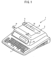
- Fig. 1 is a perspective view of a tape printing apparatus according to an embodiment of the invention
- Fig. 2 is a partially enlarged sectional view of an interior of a main body frame of the tape printing apparatus according to the embodiment of the invention
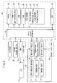
- Fig. 3 is a block diagram illustrating electric arrangements of the tape printing apparatus according to the embodiment of the invention.
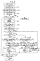
- Fig. 4 is a flowchart that illustrates printing speed control according to the embodiment of the invention.
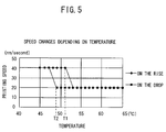
- Fig. 5 is a graph that illustrates printing speed and temperature when the printing speed control has been performed according to the embodiment of the invention
- Fig. 6 is a flowchart that illustrates changing a duty ratio according to the embodiment of the invention.
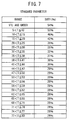
- Fig. 7 is a schematic view of a control parameter table according to the embodiment of the invention.
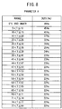
- Fig. 8 is a schematic view of a control parameter table when the temperature is rising according to the embodiment of the invention.
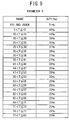
- Fig. 9 is a schematic view of a control parameter table when the temperature is rising according to another embodiment of the invention.
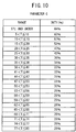
- Fig. 10 is a schematic view of a control parameter table when the temperature is dropping according to the embodiment of the invention.
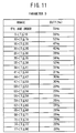
- Fig. 11 is a schematic view of a control parameter table when the temperature is dropping according to another embodiment of the invention.
- FIG. 1 is a perspective view of the tape printing apparatus 1 according to a first embodiment.
- FIG. 2 is a partially enlarged sectional view of an interior of a main body frame of the tape printing apparatus 1 according to an embodiment.
- the tape printing apparatus 1 includes, a main body frame 2, a keyboard 3 disposed at a front portion of the main body frame 2, a print mechanism 20 disposed at a rear portion within the main body frame 2, a liquid crystal display (hereinafter referred to as LCD) 22 provided immediately behind the keyboard 3 and capable of displaying characters, symbols and the like, and a cover frame 6 covering a top surface of the main body frame 2.
- a release button 4 that opens the cover frame 6 to insert and eject a tape cassette 21 (see FIG. 2), that is mounted to the print mechanism 20 that is provided at the top surface of the main body frame 2.
- a cutting operating button 5 that manually cuts a printing tape 19 is provided at a side end of the cover frame 6 (left side end in FIG. 1).
- the keyboard 3 includes, among others, character keys for inputting alphabets, numerals, symbols and the like, a space key, a return key, a linefeed key, cursor moving keys that move a cursor up, down, right or left, a size setting key that arbitrarily sets sizes of characters to be printed, character size keys that set the arbitrary character sizes to dot sizes, e.g., 16, 24, 32, 48, 64 and 96, an automatic setting key that automatically sets the character size to be printed in accordance with a tape width or a number of lines of the printing tape 19, a print key that instructs printing, an execution key that terminates various setting processes, and a power key that switches the power ON/OFF.
- character keys for inputting alphabets, numerals, symbols and the like e.g., a space key, a return key, a linefeed key, cursor moving keys that move a cursor up, down, right or left
- a size setting key that arbitrarily sets sizes of characters to be printed
- character size keys that set
- the tape cassette 21 is detachably mounted to the print mechanism 20.
- the tape cassette 21 there are disposed a tape spool 8 around which a transparent laminated film 7 is wound, an ink ribbon 9 arranged in that ink, which is melted through heating, is applied onto a base film, a take-up spool 11 that takes up the ink ribbon 9, a supply spool 13 arranged in that a double-sided adhesive tape 12 having the same width as the laminated film 7 is wound up with a separator/peel-off layer of the double-sided adhesive tape 12 being provided at the outside, and a joining roller 14 that joins the laminated film 7 and the double-sided adhesive tape 12.
- a thermal head 15 is provided at a location where the laminated film 7 and the ink ribbon 9 overlap.
- a platen roller 16 that presses the laminated film 7 and the ink ribbon 9 against the thermal head 15 and a feeding roller 17 that presses the laminated film 7 and the double-sided adhesive tape 12 against the joining roller 14 that creates the printing tape 19 are pivotally supported in a freely rotatable manner by a supporting member 18 that is pivotally attached to the main body frame 2.
- a group of heating elements (not shown) including, e.g., 128 heating elements, is provided at the thermal head 15 such that the group of heating elements are aligned and extend in a vertical direction (direction perpendicular to the plane of the drawing sheet of FIG. 2).
- the joining roller 14 and the take-up spool 11 are synchronously driven in specified rotating directions by driving a tape feeding motor 47 (see FIG. 3), the group of heating elements conduct electricity and only specified heating elements generate heat to heat the ink ribbon 9.
- the ink applied on the ink ribbon 9 is melted and thermally transferred onto the laminated film 7.
- characters, symbols, barcodes and the like, are printed onto the laminated film 7 through a plurality of dot strings, the laminated film 7 is joined with the double-sided adhesive tape 12 and further fed as the printing tape 19 in a tape feeding direction A to outside of the main body frame 2 (left-hand side in FIG. 1) as illustrated in FIGS. 1 and 2.
- JP 2-106555 (1990) A provides details of the print mechanism 20.
- FIG. 3 is a block diagram of an electric hardware configuration of the tape printing apparatus 1 of the embodiment.
- a controller 40 includes a CPU 52 that controls respective devices of the tape printing apparatus 1, and an input/output interface 50, a CGROM 53, ROMs 54, 55 and a RAM 60 that are connected to the CPU 52 through a data bus 51.
- LCDC display controller
- the ROM (dot pattern data) 54 stores therein dot pattern data used to print characters such as letters, symbols and the like upon being classified into respective typefaces such as gothic type typeface, a Mincho typeface and the like to correspond to code data of printing character sizes for each typeface, e.g., (dot sizes of 16, 24, 32, 48, 64 and 96).
- dot pattern data used to print graphic images including grayscale expressions are also stored in the ROM 54.
- the ROM 55 stores therein, among others, a display drive control program that controls the LCDC 23 in correspondence with code data of printing characters such as letters or numbers that have been input through the keyboard 3, a print drive control program that controls the thermal head 15 or the tape feeding motor 47 upon reading data of a print buffer 62, and a parameter table defining duty ratios that determine print energy that drives the thermal head 15 (see FIGS. 7 to 11).
- the RAM 60 is provided with, among others, a text memory 61, the print buffer 62, a temperature rising flag memory 63, and a parameter memory 64.
- the text memory 61 stores therein document data that have been input through the keyboard 3.
- the print buffer 62 stores therein a plurality of printing dot patterns such as letters or symbols as print data. When the temperature of the thermal head is rising, 1 is stored into the temperature rising flag memory 63 while 0 is stored when the temperature is dropping. A type of the parameter table of the presently used print energy is stored in the parameter memory 64.
- a power supply unit 65 is connected to the driving circuits 48, 49, the controller 40 and the LCDC 23. Power is supplied from the power supply unit 65 to the controller 40, the print mechanism 20 and the entire tape printing apparatus 1.
- FIG. 4 is a flowchart that illustrates printing speed control.
- FIG. 5 is a graph illustrating printing speed and temperature when the printing speed control is executed.
- 1 is set as the temperature rising flag F (S1).
- the temperature rising flag F 1 is set if the temperature of the thermal head 15 is rising and 0 is set if the temperature of the thermal head 15 is dropping.
- the temperature of the thermal head 15 is gradually raised through applied voltage so that 1 is set as the initial value.
- a temperature T of the thermal head 15 read by the thermistor 41 is then obtained via the temperature detecting circuit 42 (S3).
- S5 whether an error has occurred during temperature detection (S5) is determined. In the presence of an error (S5: YES), printing processes are terminated. If no error is present (S5: NO), normal print control corresponding to one line is performed to execute printing (S7).
- the first threshold T1 is a printing speed switching temperature when the temperature T is rising, and is a set temperature, e.g., 53 °C.
- step S17 If the present temperature T has not exceeded the first threshold T1 (S11: NO), whether printing is to be terminated is determined (S17). If printing is not to be terminated yet (S17: NO), operation returns to step S3 to read the temperature of the thermal head 15. If the present temperature T has exceeded the first threshold T1 (S11: YES), the driving circuit 49 is controlled to change the applying period of pulse with respect to the heating elements of the thermal head 15 and to reduce the printing speed (S13). After execution of printing speed reducing control, a time to start the next printing will become longer, the time of cooling of the thermal head 15 will become longer, and the temperature T of the thermal head 15 falls so that the temperature rising flag F is set to 0 (S15). Then, whether printing is to be terminated (S17) is determined. If printing is not to be terminated yet (S17: NO), the program returns to step S3 to read the temperature of the thermal head 15 again.
- the second threshold T2 is a printing speed switching temperature when the temperature is dropping, and is a set temperature that is lower than the first threshold T1, e.g., 48 °C.
- the threshold may be defined as 50 degrees and by setting an upper and lower range to 3 degrees, the first threshold T1 may be 53 degrees while the second threshold T2 may be 47 degrees.
- control is performed to change the applied period of pulse with respect to the heating elements of the thermal head 15 and to increase the printing speed (S21). After execution of such printing speed increasing control, a time to start the next printing will become shorter, the time of cooling of the thermal head 15 will become shorter, and the temperature T of the thermal head 15 rises so that the temperature rising flag F is set to 1 (S23). Then, whether printing is to be terminated (S17) is determined. If printing is not to be terminated yet (S17: NO), the program returns to step S3 to read the temperature T of the thermal head 15 again.
- a graph of a rising trend will be described first.
- printing is executed at a printing speed of 40 mm per second, and if the present temperature T of the thermal head 15 reaches the first threshold T1 of 53 °C, the printing speed is controlled to become 20 mm per second.
- the printing speed is changed to be 40 mm per second only at a point the present temperature T of the thermal head 15 has reached the second threshold T2 of 48 °C as illustrated in the graph of a dropping trend.
- the printing speed changing thresholds are different for cases in which the temperature is rising and dropping, frequent switching of the printing speed when the temperature is in the vicinity of a threshold is reduced.
- a tape printing apparatus 1 according to a second embodiment of the invention, will be described. Because the mechanical structures and electric arrangements of the tape printing apparatus 1 are identical to those of the first embodiment of the invention, descriptions thereof will be omitted.
- FIG. 6 is a flowchart that illustrates a duty ratio changing processes.
- FIGS. 7 to 11 are setting tables (parameter tables) of the duty ratios stored in the ROM 55.
- the duty ratios illustrate applying time of a driving pulse that is to be applied to the heating elements as proportions, and is a parameter of print energy.
- FIG. 7 is a schematic view illustrating a standard control parameter table
- FIG. 8 is a schematic view illustrating a control parameter table when the temperature is rising (hereinafter referred to as "parameter A")
- FIG. 9 is a schematic view illustrating a control parameter table when the temperature is rising (hereinafter referred to as "parameter B")
- FIG. 10 is a schematic view illustrating a control parameter table when the temperature is dropping (hereinafter referred to as "parameter C") and FIG. 11 is a schematic view illustrating a control parameter table when the temperature is dropping (hereinafter referred to as “parameter D").
- the duty ratios are defined as percentages depending on the temperature T. The applying time of the driving pulse is determined by the duty ratio.
- the parameter A in FIG. 8 and the parameter B in FIG. 9 are such that the ratios of the applying time of the driving pulse to be applied to the heating elements are smaller irrespective of the peripheral temperature. In other words, the applying times are shorter.
- the print energy is set in accordance with the parameter A in FIG. 8 and the parameter B in FIG. 9, the amount of heating of the heating elements will be reduced so that the temperature of the thermal head 15 tends to drop.
- the ratio of the applying time of the driving pulse to be applied to the heating elements of the parameter A in FIG. 8 is smaller than that of parameter B in FIG. 9. Accordingly, when the print energy is set in accordance with the parameter A in FIG. 8, the degree at which the temperature of the thermal head 15 drops will be larger than that when the print energy is set in accordance with the parameter B in FIG. 9.
- the parameter C in FIG. 10 and the parameter D in FIG. 11 are such that the ratios of the applying time of the driving pulse to be applied to the heating elements are larger. In other words, the applying times are longer.
- the duty ratio is set to be identical to that of the standard control parameter. Accordingly, when the print energy is set in accordance with the parameter C in FIG. 10 and the parameter D in FIG. 11, the amount of heating of the heating elements will be increased so that the temperature of the thermal head 15 tends to rise.
- the ratio of the applying time of the driving pulse to be applied to the heating elements of the parameter C in FIG. 10 is larger than that of the parameter D in FIG. 11. Accordingly, when the print energy is set in accordance with the parameter C in FIG. 10, the degree at which the temperature of the thermal head 15 rises will be larger than that when the print energy is set in accordance with the parameter D in FIG. 11.
- an initial setting (S100) is set to be the standard control parameter table as illustrated in FIG. 7.
- the temperature rising flag F is then set to 1 ((S101) if the temperature of the thermal head 15 is rising.
- the temperature of the thermal head 15 is gradually raised through the applied voltage so that 1 is set as the initial value in step S101.
- the temperature of the thermal head 15 is read by the thermistor 41 via the temperature detecting circuit 42 (S103).
- S105 whether the read present temperature T is within a specified range between a lower temperature Tmin and an upper temperature Tmax (S105) is determined. If the read present temperature T is not within the specified range (S105: NO), error is judged so no control is performed.
- a duty ratio corresponding to the present temperature T in the standard control parameter table (See FIG. 7) that has been initially set in S100 is used to perform normal print control corresponding to one line to execute printing (S107).
- the accumulated number of printing times as obtained so far is counted (S109).
- the accumulated number of printing times is correlated to the temperature increase (thermal storage) of the thermal head 15 so that this information can also be considered when changing the duty ratio so that more accurate control is possible.
- the duty ratio may be structured so as to incorporate all counted values or to select one of the counted values.
- the temperature T of the thermal head 15 read by the thermistor 41 is obtained via the temperature detecting circuit 42 (S111).
- S113 whether the read present temperature T of the thermal head 15 has exceeded the standard threshold T0 is determined (S113). If the standard threshold T0 is not exceeded (S113: NO), a parameter that determines the print energy is set to the standard control parameter table as illustrated in FIG. 7 (S115). Then whether printing is to be terminated is determined (S117). If printing is not to be terminated yet (S117: NO), the operation returns to step S107, and the print energy is determined in accordance with a duty ratio of the standard control parameter table as set in step S115 to perform print control corresponding to one line (S107). Steps S107 to S117 are repeated until the read present temperature T of the thermal head 15 has exceeded the standard threshold TO.
- control parameter B as illustrated in FIG. 9 is set as the parameter to determine the print energy (duty ratio) (S125).
- the first threshold T1 is a parameter (duty ratio) switching temperature used when the temperature is rising and may be set to, for instance, 53 °C. If the present temperature T has not exceeded the first threshold T1 yet (S127: NO), whether printing is to be terminated is determined (S117). If printing is not to be terminated yet (S117: NO), the operation returns to step S 107, determines the print energy in accordance with the set control parameter B or A and performs print control corresponding to one line (S107). Steps S107 to S113, S119 to S127 and S117 are repeated until the read present temperature T of the thermal head 15 has reached the first threshold T1 (S127).
- step S107 determines the print energy in accordance with the set control parameter B or A and performs print control corresponding to one line (S107).
- step S119 the later routines describe when the temperature T is dropping (S119: NO) because the temperature rising flag has been set to 0 in step S129.
- Whether the accumulated number of printing times as counted in step S109 has reached the default number is determined (S131). If the accumulated number of printing times has reached the default number (S131: YES), the thermal storage has progressed and the control parameter D as illustrated in FIG. 11 is set as the parameter to determine the print energy (duty ratio) (S133).
- control parameter C as illustrated in FIG. 10 is set as the parameter to determine the print energy (duty ratio) (S135).
- the second threshold T2 is a parameter (duty ratio) switching temperature used when the temperature is dropping and may be set to, for instance, 47 °C. If the present temperature T has not reached the second threshold T2 (S137: NO), whether printing is to be terminated is determined (S117). If printing is not to be terminated yet (S117: NO), the operation returns to step S107, determines the print energy in accordance with the set control parameter D or C and performs print control corresponding to one line (S107). Steps S107 to S113, S119, S131 to S137 and S117 are repeated until the read present temperature T of the thermal head 15 has reached the second threshold T2.
- step S107 determines the print energy in accordance with the set control parameter D or C and performs print control corresponding to one line (S107).
- the above processes are repeatedly executed in which the temperature is read and the thresholds are compared with the present temperature to determine a parameter table (duty ratio) to determine the print energy until printing is to be terminated. If printing is to be terminated (S117: YES), all printing processes are terminated.
- the invention is applicable to various thermal type printing apparatuses that require temperature control.
- a controller (CPU 52) preferably is implemented using a suitably programmed general purpose computer, e.g., a microprocessor, microcontroller or other processor device (CPU or MPU). It will be appreciated by those skilled in the art, that the controller can also be implemented as a single special purpose integrated circuit (e.g., ASIC) having a main or central processor section providing overall, system-level control, and separate sections dedicated to performing various different specific computations, functions and other processes under control of the central processor section.
- ASIC application specific integrated circuit
- the controller can also be implemented using a plurality of separate dedicated or programmable integrated or other electronic circuits or devices such as hardwired electronic or logic circuits such as discrete element circuits, or programmable logic devices such as PLDs, PLAs, PALs and the like.
- the controller can also be implemented using a suitably programmed general purpose computer in conjunction with one or more peripheral (e.g., integrated circuit) data and signal processing devices. Further, any device or assembly of devices on which a finite state machine capable of implementing the described procedures can be used as the controller of the invention.
Abstract
Description
For achieving the above object, according to one aspect of the present invention, there is provided a printing apparatus comprising a thermal head, a temperature measuring means for measuring a temperature of the thermal head, and a printing speed controlling means for controlling a printing speed on the basis of a measured temperature value that has been measured by the temperature measuring means, the apparatus further comprising a temperature change determining means for determining whether the temperature of the thermal head is on the rise or on the drop, and a temperature comparing means for comparing, when it has been determined by the temperature change determining means that the temperature is on the rise, a preliminarily determined first threshold with the measured temperature value and when it has been determined by the temperature change determining means that the temperature is on the drop, a preliminarily determined second threshold with the measured temperature value, wherein the printing speed controlling means performs control to reduce the printing speed when it is found out through comparison by the temperature comparing means that the measured temperature value has exceeded the first threshold while it performs control to raise the printing speed when it is found out through comparison by the temperature comparing means that the measured temperature value has fallen below the second threshold.
Steps S107 to S117 are repeated until the read present temperature T of the
Claims (33)
- A printing apparatus (1), comprising:a thermal head (15);a measurement device (41) that measures a temperature (T) of the thermal head (15); anda controller (40) that:controls a printing speed on the basis of the measured temperature (T) as measured by the measurement device (41),determines whether the measured temperature (T) of the thermal head (15) is rising or dropping,compares a preliminarily determined first threshold value (T1) with the measured temperature (T) when the temperature (T) is rising,compares a preliminarily determined second threshold value (T2) with the measured temperature (T) when the temperature (T) is dropping,controls printing by reducing the printing speed when the measured temperature (T) is greater than the first threshold value (T1), andcontrols printing by raising the printing speed when the measured temperature (T) is less than the second threshold value (T2).
- A printing apparatus, comprisingwherein the controller changes a duty ratio when the compared measured temperature is greater than the first threshold value and when the compared measured temperature is less than the second threshold value.a thermal head (15) including a plurality of heating elements;a pulse applying circuit (48) that applies driving pulses to the heating elements on the basis of a preliminary set duty ratio;a measurement device (41) that measures a temperature (T) of the thermal head (15); anda controller (40) that:determines whether the temperature (T) of the thermal head (15) is rising or dropping,changes the duty ratio on the basis of the measured temperature (T),compares a preliminarily determined first threshold value with the measured temperature when the temperature is rising, andcompares a preliminarily determined second threshold value with the measured temperature when the temperature is dropping,
- The printing apparatus according to claim 2, wherein the controller counts an accumulated time from a start of printing, and changes, when the accumulated time has exceeded a preliminarily determined third threshold value, the duty ratio to a duty ratio that is different from a case in which the third threshold value is not exceeded.
- The printing apparatus according to claim 2, wherein the controller counts an accumulated number of printed dots from a start of printing, and changes, when the accumulated number of printed dots has exceeded a preliminarily determined third threshold value, the duty ratio to a duty ratio that is different from a case in which the third threshold value is not exceeded.
- The printing apparatus according to claim 2, wherein the controller counts an accumulated number of printed lines from a start of printing, and changes, when the accumulated number of printed lines has exceeded a preliminarily determined third threshold value, the duty ratio to a duty ratio that is different from a case in which the third threshold value is not exceeded.
- The printing apparatus according to claim 3, wherein the controller counts an accumulated number of printed dots from the start of printing, and changes, when the accumulated number of printed dots has exceeded the preliminarily determined third threshold value, the duty ratio to a duty ratio that is different from the case in which the third threshold value is not exceeded.
- The printing apparatus according to claim 5, wherein the controller counts an accumulated number of printed dots from the start of printing, and changes, when the accumulated number of printed dots has exceeded the preliminarily determined third threshold value, the duty ratio to a duty ratio that is different from the case in which the third threshold value is not exceeded.
- The printing apparatus according to claim 3, wherein the controller counts an accumulated number of printed lines from the start of printing, and changes, when the accumulated number of printed lines has exceeded the preliminarily determined third threshold value, the duty ratio to a duty ratio that is different from the case in which the third threshold value is not exceeded.
- The printing apparatus according to claim 4, wherein the controller counts an accumulated number of printed lines from the start of printing, and changes, when the accumulated number of printed lines has exceeded the preliminarily determined third threshold value, the duty ratio to a duty ratio that is different from the case in which the third threshold value is not exceeded.
- The printing apparatus according to claim 6, wherein the controller counts an accumulated number of printed lines from the start of printing, and changes, when the accumulated number of printed lines has exceeded the preliminarily determined third threshold value, the duty ratio to a duty ratio that is different from the case in which the third threshold value is not exceeded.
- The printing apparatus according to one of claims 1 to 10, wherein the first threshold value is larger than the second threshold value.
- A method of controlling a printing apparatus (1) having a thermal head (15), the method comprising:measuring a temperature (T) of a thermal head (15);determining whether the temperature (T) of the thermal head (15) is rising or dropping;comparing a preliminarily determined first threshold value (T1) with the measured temperature (T) when the temperature (T) is rising;comparing a preliminarily determined second threshold value (T2) with the measured temperature (T) when the temperature (T) is dropping;controlling printing by reducing the printing speed when the compared measured temperature (T) is greater than the first threshold value (T1); andcontrolling printing by raising the printing speed when the compared measured temperature (T) is less than the second threshold value (T2).
- A method of controlling a printing apparatus (1) having a thermal head (15) including a plurality of heating elements, the method comprising:measuring the temperature (T) of the thermal head (15);determining whether the temperature (T) of the thermal head (15) is rising or dropping;changing a duty ratio on the basis of the measured temperature (T);comparing a preliminarily determined first threshold value with the measured temperature (T) when the temperature (T) is rising;comparing a preliminarily determined second threshold value with the measured temperature (T) when the temperature (T) is dropping;changing the duty ratio when the compared measured temperature (T) is greater than the first threshold value; andchanging the duty ratio when the measured temperature (T) is less than the second threshold value.
- The method according to claim 13, wherein further comprising:counting an accumulated time from a start of printing, andchanging, when the accumulated time has exceeded a preliminarily determined third threshold value, the duty ratio to a duty ratio that is different from a case in which the third threshold value is not exceeded.
- The method according to claim 13, further comprising:counting an accumulated number of printed dots from a start of printing; andchanging, when the accumulated number of printed dots has exceeded a preliminarily determined third threshold value, the duty ratio to a duty ratio that is different from a case in which the third threshold value is not exceeded.
- The method according to claim 13, further comprising:counting an accumulated number of printed lines from a start of printing; andchanging, when the accumulated number of printed lines has exceeded a preliminarily determined third threshold value, the duty ratio to a duty ratio that is different from a case in which the third threshold value is not exceeded.
- The method according to claim 14, further comprising:counting an accumulated number of printed dots from the start of printing;and changing, when the accumulated number of printed dots has exceeded the preliminarily determined third threshold value, the duty ratio to a duty ratio that is different from the case in which the third threshold value is not exceeded.
- The method according to claim 16, further comprising:counting an accumulated number of printed dots from the start of printing, andchanging, when the accumulated number of printed dots has exceeded a preliminarily determined third threshold value, the duty ratio to a duty ratio that is different from the case in which the third threshold value is not exceeded.
- The method according to claim 14, further comprising:counting an accumulated number of printed lines from a start of printing, andchanging, when the accumulated number of printed lines has exceeded the preliminarily determined third threshold value, the duty ratio to a duty ratio that is different from the case in which the third threshold value is not exceeded.
- The method according to claim 15, further comprising:counting an accumulated number of printed lines from the start of printing, andchanging, when the accumulated number of printed lines has exceeded the preliminarily determined third threshold value, the duty ratio to a duty ratio that is different from the case in which the third threshold value is not exceeded.
- The method according to claim 17, further comprising:counting an accumulated number of printed lines from the start of printing, andchanging, when the accumulated number of printed lines has exceeded the preliminarily determined third threshold value, the duty ratio to a duty ratio that is different from the case in which the third threshold value is not exceeded.
- The method according to one of claims 12 to 21, wherein the first threshold value is larger than the second threshold value.
- A printing apparatus (1) comprising:wherein the printing speed controlling means (40) performs control to reduce the printing speed when it is found out through comparison by the temperature comparing means that the measured temperature value has exceeded the first threshold (T1) while it performs controlling to raise the printing speed when it is found out through comparison by the temperature comparing means that the measured temperature value has fallen below the second threshold (T2).a thermal head (15), a temperature measuring means (41) for measuring a temperature (T) of the thermal head (15), and a printing speed controlling means (40) for controlling a printing speed on the basis of a measured temperature value as measured by the temperature measuring means (41);a temperature change determining means for determining whether the temperature (T) of the thermal head (15) is on the rise or on the drop; anda temperature comparing means for comparing, when it has been determined by the temperature change determining means (41) that the temperature (T) is on the rise, a preliminarily determined first threshold (T1) with the measured temperature value, and when it has been determined by the temperature change determining means (41) that the temperature (T) is on the drop, a preliminarily determined second threshold (T2) with the measured temperature value,
- A printing apparatus (1) comprising:wherein the duty ratio changing means changes the duty ratio when it is found out through comparison by the temperature comparing means that the measured temperature value has exceeded the first threshold and when the measured temperature value has fallen below the second threshold.a thermal head (15) including a plurality of heating elements, a pulse impressing means (48) for impressing driving pulses to the heating elements on the basis of a preliminary set duty ratio, and a temperature measuring means (41) for measuring a temperature of the thermal head (15);a temperature change determining means for determining whether the temperature (T) of the thermal head (15) is on the rise or on the drop;a duty ratio changing means for changing the duty ratio on the basis of the measured temperature value that has been measured by the temperature measuring means (41); anda temperature comparing means for comparing, when it has been determined by the temperature change determining means that the temperature (T) is on the rise, a preliminarily determined first threshold (T1) with the measured temperature value and when it has been determined by the temperature change determining means that the temperature (T) is on the drop, a preliminarily determined second threshold (T2) with the measured temperature value,
- The printing apparatus according to claim 24, further comprising:an accumulating and counting means for counting an accumulating time from start of printing, wherein the duty ratio changing means changes, when the value counted by the accumulating and counting means has exceeded a preliminarily determined third threshold, the duty ratio to a duty ratio that is different from a case in which the third threshold is not exceeded.
- The printing apparatus according to claim 24, further comprising:an accumulating and counting means for counting an accumulated number of printed dots from start of printing, wherein the duty ratio changing means changes, when the value counted by the accumulating and counting means has exceeded a preliminarily determined third threshold, the duty ratio to a duty ratio that is different from a case in which the third threshold is not exceeded.
- The printing apparatus according to claim 24, further comprising:an accumulating and counting means for counting an accumulated number of printed lines from start of printing, wherein the duty ratio changing means changes, when the value counted by the accumulating and counting means has exceeded a preliminarily determined third threshold, the duty ratio to a duty ratio that is different from a case in which the third threshold is not exceeded.
- The printing apparatus according to claim 25, further comprising:an accumulating and counting means for counting an accumulated number of printed dots from start of printing, wherein the duty ratio changing means changes, when the value counted by the accumulating and counting means has exceeded a preliminarily determined third threshold, the duty ratio to a duty ratio that is different from a case in which the third threshold is not exceeded.
- The printing apparatus according to claim 28, further comprising:an accumulating and counting means for counting an accumulated number of printed dots from start of printing, wherein the duty ratio changing means changes, when the value counted by the accumulating and counting means has exceeded a preliminarily determined third threshold, the duty ratio to a duty ratio that is different from a case in which the third threshold is not exceeded.
- The printing apparatus according to claim 25, further comprising:an accumulating and counting means for counting an accumulated number of printed lines from start of printing, wherein the duty ratio changing means changes, when the value counted by the accumulating and counting means has exceeded a preliminarily determined third threshold, the duty ratio to a duty ratio that is different from a case in which the third threshold is not exceeded.
- The printing apparatus according to claim 26, further comprising:an accumulating and counting means for counting an accumulated number of printed lines from start of printing, wherein the duty ratio changing means changes, when the value counted by the accumulating and counting means has exceeded a preliminarily determined third threshold, the duty ratio to a duty ratio that is different from a case in which the third threshold is not exceeded.
- The printing apparatus according to claim 28, further comprising:an accumulating and counting means for counting an accumulated number of printed lines from start of printing, wherein the duty ratio changing means changes, when the value counted by the accumulating and counting means has exceeded a preliminarily determined third threshold, the duty ratio to a duty ratio that is different from a case in which the third threshold is not exceeded.
- The printing apparatus according to one of claims 23 to 32, wherein the first threshold is larger than the second threshold.
Priority Applications (1)
| Application Number | Priority Date | Filing Date | Title |
|---|---|---|---|
| EP11157845.6A EP2347908B1 (en) | 2003-09-26 | 2004-09-17 | Printing apparatus and method of controlling it |
Applications Claiming Priority (2)
| Application Number | Priority Date | Filing Date | Title |
|---|---|---|---|
| JP2003335741 | 2003-09-26 | ||
| JP2003335741A JP2005096377A (en) | 2003-09-26 | 2003-09-26 | Printing device and printing method |
Related Child Applications (1)
| Application Number | Title | Priority Date | Filing Date |
|---|---|---|---|
| EP11157845.6 Division-Into | 2011-03-11 |
Publications (3)
| Publication Number | Publication Date |
|---|---|
| EP1518696A2 true EP1518696A2 (en) | 2005-03-30 |
| EP1518696A3 EP1518696A3 (en) | 2005-06-01 |
| EP1518696B1 EP1518696B1 (en) | 2011-05-04 |
Family
ID=34191529
Family Applications (2)
| Application Number | Title | Priority Date | Filing Date |
|---|---|---|---|
| EP04022226A Not-in-force EP1518696B1 (en) | 2003-09-26 | 2004-09-17 | Thermal printing apparatus and printing method |
| EP11157845.6A Not-in-force EP2347908B1 (en) | 2003-09-26 | 2004-09-17 | Printing apparatus and method of controlling it |
Family Applications After (1)
| Application Number | Title | Priority Date | Filing Date |
|---|---|---|---|
| EP11157845.6A Not-in-force EP2347908B1 (en) | 2003-09-26 | 2004-09-17 | Printing apparatus and method of controlling it |
Country Status (6)
| Country | Link |
|---|---|
| US (1) | US7091999B2 (en) |
| EP (2) | EP1518696B1 (en) |
| JP (1) | JP2005096377A (en) |
| CN (1) | CN1315655C (en) |
| AT (1) | ATE507977T1 (en) |
| DE (1) | DE602004032501D1 (en) |
Cited By (1)
| Publication number | Priority date | Publication date | Assignee | Title |
|---|---|---|---|---|
| EP3340595A1 (en) * | 2016-12-21 | 2018-06-27 | Seiko Epson Corporation | Printing apparatus and power supply unit for printing apparatus |
Families Citing this family (23)
| Publication number | Priority date | Publication date | Assignee | Title |
|---|---|---|---|---|
| US7040822B2 (en) * | 2003-06-04 | 2006-05-09 | Hellermanntyton Corporation | Portable printing system |
| US7101100B2 (en) * | 2004-10-14 | 2006-09-05 | Seiko Instruments Inc. | Printer apparatus |
| JP2007078875A (en) * | 2005-09-12 | 2007-03-29 | Canon Inc | Image forming apparatus and recording material conveyance method |
| JP2007181982A (en) * | 2006-01-06 | 2007-07-19 | Alps Electric Co Ltd | Printer |
| JP4906762B2 (en) | 2008-03-17 | 2012-03-28 | キヤノン株式会社 | Printing apparatus and printing apparatus control method |
| JP5256893B2 (en) * | 2008-07-07 | 2013-08-07 | セイコーエプソン株式会社 | RECORDING DEVICE, CONTROL METHOD AND CONTROL PROGRAM FOR RECORDING DEVICE |
| JP5526606B2 (en) * | 2009-05-28 | 2014-06-18 | ブラザー工業株式会社 | Printing device |
| JP2012011599A (en) * | 2010-06-29 | 2012-01-19 | Toshiba Tec Corp | Printer and program |
| JP2013052021A (en) * | 2011-09-01 | 2013-03-21 | Teijin Pharma Ltd | Oxygen concentrator |
| JP5739848B2 (en) * | 2012-08-03 | 2015-06-24 | 東芝テック株式会社 | Printing apparatus and printing method |
| CN103112254B (en) * | 2013-02-01 | 2015-09-09 | 深圳市理邦精密仪器股份有限公司 | Thermal head heat regulation device, method and thermal printer |
| CN103202691B (en) * | 2013-03-21 | 2014-12-10 | 深圳市理邦精密仪器股份有限公司 | Method and device for improving electrocardiogram waveform data printing efficiency |
| JP6198690B2 (en) * | 2014-07-29 | 2017-09-20 | 東芝テック株式会社 | Thermal printer and print control program thereof |
| CN107111807B8 (en) * | 2014-10-03 | 2022-10-11 | 艾利丹尼森零售信息服务公司 | Customizable food freshness printer start-up wizard |
| US10112385B2 (en) | 2014-10-31 | 2018-10-30 | Hewlett-Packard Development Company, L.P. | Ambient temperature based flow rates |
| CN105249960B (en) * | 2015-09-28 | 2017-12-08 | 康泰医学系统(秦皇岛)股份有限公司 | A kind of electrocardiograph thermal print protection circuit and method |
| CN106476455A (en) * | 2016-09-12 | 2017-03-08 | 北京三快在线科技有限公司 | The control method of printing, device and printer |
| JP6720799B2 (en) * | 2016-09-23 | 2020-07-08 | カシオ計算機株式会社 | Printing device, printing device control method, and program |
| CN106864041B (en) * | 2016-12-28 | 2019-06-11 | 虎丘影像(苏州)有限公司 | A kind of temperature control system and method for image printer |
| CN110225826B (en) * | 2017-01-27 | 2020-10-16 | 惠普发展公司,有限责任合伙企业 | Printing device temperature management |
| CN107244146B (en) * | 2017-05-31 | 2018-08-24 | 青岛海信智能商用系统股份有限公司 | Thermal printing head temperature-control circuit and thermal printer |
| CN109532240B (en) * | 2018-11-08 | 2020-10-30 | 福建联迪商用设备有限公司 | Thermal inertia effect compensation method, control module, terminal and time control method |
| JP7379179B2 (en) | 2020-01-16 | 2023-11-14 | 東芝テック株式会社 | thermal printer |
Citations (1)
| Publication number | Priority date | Publication date | Assignee | Title |
|---|---|---|---|---|
| JPS6420340U (en) | 1987-07-28 | 1989-02-01 |
Family Cites Families (18)
| Publication number | Priority date | Publication date | Assignee | Title |
|---|---|---|---|---|
| JPS6189055A (en) * | 1984-10-08 | 1986-05-07 | Fuji Xerox Co Ltd | Speed control device for thermosensitive recording |
| JPS63173665A (en) * | 1987-01-13 | 1988-07-18 | Konica Corp | Image recorder contriving uniformization of recorded density |
| JPS63260461A (en) * | 1987-04-17 | 1988-10-27 | Hitachi Koki Co Ltd | Controller for impact printer |
| US5331340A (en) * | 1988-05-02 | 1994-07-19 | Canon Kabushiki Kaisha | Thermal head with control means for maintaining head temperature within a range |
| JPH02106555A (en) | 1988-10-14 | 1990-04-18 | Brother Ind Ltd | Tape containing cassette |
| EP0408122B1 (en) * | 1989-07-10 | 1996-12-18 | Psi Printer Systems International Gmbh | Circuit for a matrix printer |
| US5986684A (en) * | 1992-12-08 | 1999-11-16 | Ricoh Company, Ltd. | Thermal printing system having function for preventing over heating of thermal head |
| US5524993A (en) * | 1993-10-06 | 1996-06-11 | Monarch Marking Systems, Inc. | Automatic print speed control for a barcode printer |
| JPH07314763A (en) * | 1994-05-30 | 1995-12-05 | Riso Kagaku Corp | Controlling method of thermal head for thermosensitive plate making and device therefor |
| JP3258878B2 (en) * | 1994-12-02 | 2002-02-18 | セイコーエプソン株式会社 | Drive control method and apparatus for thermal head |
| JP3294117B2 (en) * | 1996-01-23 | 2002-06-24 | セイコーエプソン株式会社 | PRINTING APPARATUS AND EXPOSURE MASK PATTERN CREATING METHOD BY PRINTING APPARATUS |
| JP3062148B2 (en) | 1998-03-19 | 2000-07-10 | 静岡日本電気株式会社 | Thermal recording method and thermal recording apparatus |
| DE19835693A1 (en) * | 1998-08-07 | 2000-02-10 | Bosch Gmbh Robert | Fuel injector |
| JP2000185424A (en) * | 1998-12-21 | 2000-07-04 | Seiko Instruments Inc | Method for controlling history of thermal printer |
| US6601941B1 (en) * | 2000-07-14 | 2003-08-05 | Christopher Dane Jones | Method and apparatus for predicting and limiting maximum printhead chip temperature in an ink jet printer |
| CN1255280C (en) * | 2000-09-20 | 2006-05-10 | 明基电通股份有限公司 | Driver of ink-jet head with temp sensing function |
| US6655772B2 (en) * | 2001-03-21 | 2003-12-02 | Canon Kabushiki Kaisha | Printing apparatus and printhead temperature management method |
| CN2507649Y (en) * | 2001-08-21 | 2002-08-28 | 山东华菱电子有限公司 | Printing unit of thermal printer |
-
2003
- 2003-09-26 JP JP2003335741A patent/JP2005096377A/en active Pending
-
2004
- 2004-08-17 US US10/919,446 patent/US7091999B2/en active Active
- 2004-09-17 AT AT04022226T patent/ATE507977T1/en not_active IP Right Cessation
- 2004-09-17 DE DE602004032501T patent/DE602004032501D1/en active Active
- 2004-09-17 EP EP04022226A patent/EP1518696B1/en not_active Not-in-force
- 2004-09-17 EP EP11157845.6A patent/EP2347908B1/en not_active Not-in-force
- 2004-09-24 CN CNB2004100826499A patent/CN1315655C/en not_active Expired - Fee Related
Patent Citations (1)
| Publication number | Priority date | Publication date | Assignee | Title |
|---|---|---|---|---|
| JPS6420340U (en) | 1987-07-28 | 1989-02-01 |
Cited By (2)
| Publication number | Priority date | Publication date | Assignee | Title |
|---|---|---|---|---|
| EP3340595A1 (en) * | 2016-12-21 | 2018-06-27 | Seiko Epson Corporation | Printing apparatus and power supply unit for printing apparatus |
| US10350920B2 (en) | 2016-12-21 | 2019-07-16 | Seiko Epson Corporation | Printing apparatus and power supply unit for printing apparatus |
Also Published As
| Publication number | Publication date |
|---|---|
| DE602004032501D1 (en) | 2011-06-16 |
| ATE507977T1 (en) | 2011-05-15 |
| US7091999B2 (en) | 2006-08-15 |
| JP2005096377A (en) | 2005-04-14 |
| EP1518696A3 (en) | 2005-06-01 |
| EP2347908B1 (en) | 2013-11-20 |
| EP2347908A1 (en) | 2011-07-27 |
| CN1315655C (en) | 2007-05-16 |
| US20050068403A1 (en) | 2005-03-31 |
| EP1518696B1 (en) | 2011-05-04 |
| CN1600554A (en) | 2005-03-30 |
Similar Documents
| Publication | Publication Date | Title |
|---|---|---|
| EP1518696B1 (en) | Thermal printing apparatus and printing method | |
| EP0652110A2 (en) | Tape printing apparatus having manual tape cutting device | |
| EP2497644B1 (en) | Thermal printer and method for controlling current passage therein | |
| JP5152060B2 (en) | PRINT TAPE AND TAP PRINTING DEVICE USING PRINT TAPE AND METHOD OF JUDGING PRINT TAPE AND REMAINING RATE FROM MARK PRINTED ON PRINT TAPE | |
| US10350907B2 (en) | Printing apparatus, printing system, printing control method and computer-readable recording medium | |
| JP5929901B2 (en) | Thermal head printing speed control method | |
| US10752016B2 (en) | Printing apparatus, printing system, printing control method and computer-readable recording medium | |
| JP4631237B2 (en) | Thermal recording device | |
| US8780155B2 (en) | Tape cassette and tape printing apparatus | |
| US10350906B2 (en) | Printing apparatus, printing system, printing control method and computer-readable recording medium | |
| US10336096B2 (en) | Printing apparatus, control method of printing apparatus, and non-transitory computer readable recording medium | |
| US5961227A (en) | Thermal recording apparatus | |
| JP2018083303A (en) | Printer | |
| JP3242256B2 (en) | Printing device | |
| JP4000925B2 (en) | Thermal recording device | |
| JP3031158B2 (en) | Printing device | |
| CN106985554B (en) | Printer with a movable platen | |
| JP3031157B2 (en) | Printing device | |
| JPH1178099A (en) | Thermal recorder | |
| JPH09277579A (en) | Printing equipment | |
| JP2012035472A (en) | Printer | |
| JP2005280100A (en) | Thermal printer | |
| JP2016182708A (en) | Printer | |
| JP2003080757A (en) | Thermal recorder | |
| JP2004181794A (en) | Tape printer and its printing control method, program and storage medium |
Legal Events
| Date | Code | Title | Description |
|---|---|---|---|
| PUAI | Public reference made under article 153(3) epc to a published international application that has entered the european phase |
Free format text: ORIGINAL CODE: 0009012 |
|
| AK | Designated contracting states |
Kind code of ref document: A2 Designated state(s): AT BE BG CH CY CZ DE DK EE ES FI FR GB GR HU IE IT LI LU MC NL PL PT RO SE SI SK TR |
|
| AX | Request for extension of the european patent |
Extension state: AL HR LT LV MK |
|
| PUAL | Search report despatched |
Free format text: ORIGINAL CODE: 0009013 |
|
| AK | Designated contracting states |
Kind code of ref document: A3 Designated state(s): AT BE BG CH CY CZ DE DK EE ES FI FR GB GR HU IE IT LI LU MC NL PL PT RO SE SI SK TR |
|
| AX | Request for extension of the european patent |
Extension state: AL HR LT LV MK |
|
| 17P | Request for examination filed |
Effective date: 20050923 |
|
| AKX | Designation fees paid |
Designated state(s): AT BE BG CH CY CZ DE DK EE ES FI FR GB GR HU IE IT LI LU MC NL PL PT RO SE SI SK TR |
|
| 17Q | First examination report despatched |
Effective date: 20090409 |
|
| GRAP | Despatch of communication of intention to grant a patent |
Free format text: ORIGINAL CODE: EPIDOSNIGR1 |
|
| GRAS | Grant fee paid |
Free format text: ORIGINAL CODE: EPIDOSNIGR3 |
|
| GRAA | (expected) grant |
Free format text: ORIGINAL CODE: 0009210 |
|
| AK | Designated contracting states |
Kind code of ref document: B1 Designated state(s): AT BE BG CH CY CZ DE DK EE ES FI FR GB GR HU IE IT LI LU MC NL PL PT RO SE SI SK TR |
|
| REG | Reference to a national code |
Ref country code: GB Ref legal event code: FG4D |
|
| REG | Reference to a national code |
Ref country code: CH Ref legal event code: EP |
|
| REG | Reference to a national code |
Ref country code: IE Ref legal event code: FG4D |
|
| REF | Corresponds to: |
Ref document number: 602004032501 Country of ref document: DE Date of ref document: 20110616 Kind code of ref document: P |
|
| REG | Reference to a national code |
Ref country code: DE Ref legal event code: R096 Ref document number: 602004032501 Country of ref document: DE Effective date: 20110616 |
|
| REG | Reference to a national code |
Ref country code: NL Ref legal event code: VDEP Effective date: 20110504 |
|
| PG25 | Lapsed in a contracting state [announced via postgrant information from national office to epo] |
Ref country code: PT Free format text: LAPSE BECAUSE OF FAILURE TO SUBMIT A TRANSLATION OF THE DESCRIPTION OR TO PAY THE FEE WITHIN THE PRESCRIBED TIME-LIMIT Effective date: 20110905 Ref country code: SE Free format text: LAPSE BECAUSE OF FAILURE TO SUBMIT A TRANSLATION OF THE DESCRIPTION OR TO PAY THE FEE WITHIN THE PRESCRIBED TIME-LIMIT Effective date: 20110504 |
|
| PG25 | Lapsed in a contracting state [announced via postgrant information from national office to epo] |
Ref country code: AT Free format text: LAPSE BECAUSE OF FAILURE TO SUBMIT A TRANSLATION OF THE DESCRIPTION OR TO PAY THE FEE WITHIN THE PRESCRIBED TIME-LIMIT Effective date: 20110504 Ref country code: CY Free format text: LAPSE BECAUSE OF FAILURE TO SUBMIT A TRANSLATION OF THE DESCRIPTION OR TO PAY THE FEE WITHIN THE PRESCRIBED TIME-LIMIT Effective date: 20110504 Ref country code: BE Free format text: LAPSE BECAUSE OF FAILURE TO SUBMIT A TRANSLATION OF THE DESCRIPTION OR TO PAY THE FEE WITHIN THE PRESCRIBED TIME-LIMIT Effective date: 20110504 Ref country code: FI Free format text: LAPSE BECAUSE OF FAILURE TO SUBMIT A TRANSLATION OF THE DESCRIPTION OR TO PAY THE FEE WITHIN THE PRESCRIBED TIME-LIMIT Effective date: 20110504 Ref country code: GR Free format text: LAPSE BECAUSE OF FAILURE TO SUBMIT A TRANSLATION OF THE DESCRIPTION OR TO PAY THE FEE WITHIN THE PRESCRIBED TIME-LIMIT Effective date: 20110805 Ref country code: SI Free format text: LAPSE BECAUSE OF FAILURE TO SUBMIT A TRANSLATION OF THE DESCRIPTION OR TO PAY THE FEE WITHIN THE PRESCRIBED TIME-LIMIT Effective date: 20110504 Ref country code: ES Free format text: LAPSE BECAUSE OF FAILURE TO SUBMIT A TRANSLATION OF THE DESCRIPTION OR TO PAY THE FEE WITHIN THE PRESCRIBED TIME-LIMIT Effective date: 20110815 |
|
| PG25 | Lapsed in a contracting state [announced via postgrant information from national office to epo] |
Ref country code: NL Free format text: LAPSE BECAUSE OF FAILURE TO SUBMIT A TRANSLATION OF THE DESCRIPTION OR TO PAY THE FEE WITHIN THE PRESCRIBED TIME-LIMIT Effective date: 20110504 |
|
| PG25 | Lapsed in a contracting state [announced via postgrant information from national office to epo] |
Ref country code: CZ Free format text: LAPSE BECAUSE OF FAILURE TO SUBMIT A TRANSLATION OF THE DESCRIPTION OR TO PAY THE FEE WITHIN THE PRESCRIBED TIME-LIMIT Effective date: 20110504 Ref country code: EE Free format text: LAPSE BECAUSE OF FAILURE TO SUBMIT A TRANSLATION OF THE DESCRIPTION OR TO PAY THE FEE WITHIN THE PRESCRIBED TIME-LIMIT Effective date: 20110504 |
|
| PG25 | Lapsed in a contracting state [announced via postgrant information from national office to epo] |
Ref country code: PL Free format text: LAPSE BECAUSE OF FAILURE TO SUBMIT A TRANSLATION OF THE DESCRIPTION OR TO PAY THE FEE WITHIN THE PRESCRIBED TIME-LIMIT Effective date: 20110504 Ref country code: DK Free format text: LAPSE BECAUSE OF FAILURE TO SUBMIT A TRANSLATION OF THE DESCRIPTION OR TO PAY THE FEE WITHIN THE PRESCRIBED TIME-LIMIT Effective date: 20110504 Ref country code: RO Free format text: LAPSE BECAUSE OF FAILURE TO SUBMIT A TRANSLATION OF THE DESCRIPTION OR TO PAY THE FEE WITHIN THE PRESCRIBED TIME-LIMIT Effective date: 20110504 Ref country code: SK Free format text: LAPSE BECAUSE OF FAILURE TO SUBMIT A TRANSLATION OF THE DESCRIPTION OR TO PAY THE FEE WITHIN THE PRESCRIBED TIME-LIMIT Effective date: 20110504 |
|
| PLBE | No opposition filed within time limit |
Free format text: ORIGINAL CODE: 0009261 |
|
| STAA | Information on the status of an ep patent application or granted ep patent |
Free format text: STATUS: NO OPPOSITION FILED WITHIN TIME LIMIT |
|
| 26N | No opposition filed |
Effective date: 20120207 |
|
| PG25 | Lapsed in a contracting state [announced via postgrant information from national office to epo] |
Ref country code: MC Free format text: LAPSE BECAUSE OF NON-PAYMENT OF DUE FEES Effective date: 20110930 |
|
| REG | Reference to a national code |
Ref country code: CH Ref legal event code: PL |
|
| PG25 | Lapsed in a contracting state [announced via postgrant information from national office to epo] |
Ref country code: IT Free format text: LAPSE BECAUSE OF FAILURE TO SUBMIT A TRANSLATION OF THE DESCRIPTION OR TO PAY THE FEE WITHIN THE PRESCRIBED TIME-LIMIT Effective date: 20110504 |
|
| REG | Reference to a national code |
Ref country code: DE Ref legal event code: R097 Ref document number: 602004032501 Country of ref document: DE Effective date: 20120207 |
|
| REG | Reference to a national code |
Ref country code: IE Ref legal event code: MM4A |
|
| PG25 | Lapsed in a contracting state [announced via postgrant information from national office to epo] |
Ref country code: IE Free format text: LAPSE BECAUSE OF NON-PAYMENT OF DUE FEES Effective date: 20110917 Ref country code: LI Free format text: LAPSE BECAUSE OF NON-PAYMENT OF DUE FEES Effective date: 20110930 Ref country code: CH Free format text: LAPSE BECAUSE OF NON-PAYMENT OF DUE FEES Effective date: 20110930 |
|
| PG25 | Lapsed in a contracting state [announced via postgrant information from national office to epo] |
Ref country code: LU Free format text: LAPSE BECAUSE OF NON-PAYMENT OF DUE FEES Effective date: 20110917 |
|
| PG25 | Lapsed in a contracting state [announced via postgrant information from national office to epo] |
Ref country code: BG Free format text: LAPSE BECAUSE OF FAILURE TO SUBMIT A TRANSLATION OF THE DESCRIPTION OR TO PAY THE FEE WITHIN THE PRESCRIBED TIME-LIMIT Effective date: 20110804 |
|
| PG25 | Lapsed in a contracting state [announced via postgrant information from national office to epo] |
Ref country code: TR Free format text: LAPSE BECAUSE OF FAILURE TO SUBMIT A TRANSLATION OF THE DESCRIPTION OR TO PAY THE FEE WITHIN THE PRESCRIBED TIME-LIMIT Effective date: 20110504 |
|
| PG25 | Lapsed in a contracting state [announced via postgrant information from national office to epo] |
Ref country code: HU Free format text: LAPSE BECAUSE OF FAILURE TO SUBMIT A TRANSLATION OF THE DESCRIPTION OR TO PAY THE FEE WITHIN THE PRESCRIBED TIME-LIMIT Effective date: 20110504 |
|
| REG | Reference to a national code |
Ref country code: FR Ref legal event code: PLFP Year of fee payment: 13 |
|
| REG | Reference to a national code |
Ref country code: FR Ref legal event code: PLFP Year of fee payment: 14 |
|
| PGFP | Annual fee paid to national office [announced via postgrant information from national office to epo] |
Ref country code: FR Payment date: 20170823 Year of fee payment: 14 Ref country code: GB Payment date: 20170829 Year of fee payment: 14 |
|
| PGFP | Annual fee paid to national office [announced via postgrant information from national office to epo] |
Ref country code: DE Payment date: 20170928 Year of fee payment: 14 |
|
| REG | Reference to a national code |
Ref country code: DE Ref legal event code: R119 Ref document number: 602004032501 Country of ref document: DE |
|
| GBPC | Gb: european patent ceased through non-payment of renewal fee |
Effective date: 20180917 |
|
| PG25 | Lapsed in a contracting state [announced via postgrant information from national office to epo] |
Ref country code: DE Free format text: LAPSE BECAUSE OF NON-PAYMENT OF DUE FEES Effective date: 20190402 |
|
| PG25 | Lapsed in a contracting state [announced via postgrant information from national office to epo] |
Ref country code: FR Free format text: LAPSE BECAUSE OF NON-PAYMENT OF DUE FEES Effective date: 20180930 |
|
| PG25 | Lapsed in a contracting state [announced via postgrant information from national office to epo] |
Ref country code: GB Free format text: LAPSE BECAUSE OF NON-PAYMENT OF DUE FEES Effective date: 20180917 |