EP1519616A2 - Ethernet passive optical network integrating image broadcast and data communication based on time division multiplexing - Google Patents
Ethernet passive optical network integrating image broadcast and data communication based on time division multiplexing Download PDFInfo
- Publication number
- EP1519616A2 EP1519616A2 EP04013477A EP04013477A EP1519616A2 EP 1519616 A2 EP1519616 A2 EP 1519616A2 EP 04013477 A EP04013477 A EP 04013477A EP 04013477 A EP04013477 A EP 04013477A EP 1519616 A2 EP1519616 A2 EP 1519616A2
- Authority
- EP
- European Patent Office
- Prior art keywords
- broadcast
- image
- signal
- optical
- time
- Prior art date
- Legal status (The legal status is an assumption and is not a legal conclusion. Google has not performed a legal analysis and makes no representation as to the accuracy of the status listed.)
- Granted
Links
Images


Classifications
-
- H—ELECTRICITY
- H04—ELECTRIC COMMUNICATION TECHNIQUE
- H04L—TRANSMISSION OF DIGITAL INFORMATION, e.g. TELEGRAPHIC COMMUNICATION
- H04L12/00—Data switching networks
- H04L12/28—Data switching networks characterised by path configuration, e.g. LAN [Local Area Networks] or WAN [Wide Area Networks]
-
- H—ELECTRICITY
- H04—ELECTRIC COMMUNICATION TECHNIQUE
- H04J—MULTIPLEX COMMUNICATION
- H04J14/00—Optical multiplex systems
- H04J14/02—Wavelength-division multiplex systems
- H04J14/0226—Fixed carrier allocation, e.g. according to service
-
- H—ELECTRICITY
- H04—ELECTRIC COMMUNICATION TECHNIQUE
- H04J—MULTIPLEX COMMUNICATION
- H04J14/00—Optical multiplex systems
- H04J14/02—Wavelength-division multiplex systems
- H04J14/0227—Operation, administration, maintenance or provisioning [OAMP] of WDM networks, e.g. media access, routing or wavelength allocation
- H04J14/0228—Wavelength allocation for communications one-to-all, e.g. broadcasting wavelengths
- H04J14/023—Wavelength allocation for communications one-to-all, e.g. broadcasting wavelengths in WDM passive optical networks [WDM-PON]
- H04J14/0232—Wavelength allocation for communications one-to-all, e.g. broadcasting wavelengths in WDM passive optical networks [WDM-PON] for downstream transmission
-
- H—ELECTRICITY
- H04—ELECTRIC COMMUNICATION TECHNIQUE
- H04J—MULTIPLEX COMMUNICATION
- H04J14/00—Optical multiplex systems
- H04J14/02—Wavelength-division multiplex systems
- H04J14/0227—Operation, administration, maintenance or provisioning [OAMP] of WDM networks, e.g. media access, routing or wavelength allocation
- H04J14/0241—Wavelength allocation for communications one-to-one, e.g. unicasting wavelengths
- H04J14/0242—Wavelength allocation for communications one-to-one, e.g. unicasting wavelengths in WDM-PON
- H04J14/0245—Wavelength allocation for communications one-to-one, e.g. unicasting wavelengths in WDM-PON for downstream transmission, e.g. optical line terminal [OLT] to ONU
- H04J14/0247—Sharing one wavelength for at least a group of ONUs
-
- H—ELECTRICITY
- H04—ELECTRIC COMMUNICATION TECHNIQUE
- H04J—MULTIPLEX COMMUNICATION
- H04J14/00—Optical multiplex systems
- H04J14/02—Wavelength-division multiplex systems
- H04J14/0227—Operation, administration, maintenance or provisioning [OAMP] of WDM networks, e.g. media access, routing or wavelength allocation
- H04J14/0241—Wavelength allocation for communications one-to-one, e.g. unicasting wavelengths
- H04J14/0242—Wavelength allocation for communications one-to-one, e.g. unicasting wavelengths in WDM-PON
- H04J14/0249—Wavelength allocation for communications one-to-one, e.g. unicasting wavelengths in WDM-PON for upstream transmission, e.g. ONU-to-OLT or ONU-to-ONU
- H04J14/0252—Sharing one wavelength for at least a group of ONUs, e.g. for transmissions from-ONU-to-OLT or from-ONU-to-ONU
-
- H—ELECTRICITY
- H04—ELECTRIC COMMUNICATION TECHNIQUE
- H04J—MULTIPLEX COMMUNICATION
- H04J14/00—Optical multiplex systems
- H04J14/02—Wavelength-division multiplex systems
- H04J14/0278—WDM optical network architectures
- H04J14/0282—WDM tree architectures
-
- H—ELECTRICITY
- H04—ELECTRIC COMMUNICATION TECHNIQUE
- H04Q—SELECTING
- H04Q11/00—Selecting arrangements for multiplex systems
- H04Q11/0001—Selecting arrangements for multiplex systems using optical switching
- H04Q11/0062—Network aspects
- H04Q11/0067—Provisions for optical access or distribution networks, e.g. Gigabit Ethernet Passive Optical Network (GE-PON), ATM-based Passive Optical Network (A-PON), PON-Ring
-
- H—ELECTRICITY
- H04—ELECTRIC COMMUNICATION TECHNIQUE
- H04Q—SELECTING
- H04Q11/00—Selecting arrangements for multiplex systems
- H04Q11/0001—Selecting arrangements for multiplex systems using optical switching
- H04Q11/0062—Network aspects
- H04Q11/0066—Provisions for optical burst or packet networks
-
- H—ELECTRICITY
- H04—ELECTRIC COMMUNICATION TECHNIQUE
- H04Q—SELECTING
- H04Q11/00—Selecting arrangements for multiplex systems
- H04Q11/0001—Selecting arrangements for multiplex systems using optical switching
- H04Q11/0062—Network aspects
- H04Q11/0071—Provisions for the electrical-optical layer interface
Definitions
- the present invention relates to optical transmission, and more particularly to an Ethernet passive optical network (Ethernet-PON) for providing high-volume, high-speed data services and real-time broadcast/image services to subscribers.
- Ethernet-PON Ethernet passive optical network
- PONs such as a PON based on ATM (ATM-PON), a PON based on WDM (WDM-PON) and a PON based on Ethernet (Ethernet-PON or EPON).
- ATM-PON ATM-PON
- WDM-PON PON based on WDM
- Ethernet-PON or EPON PON based on Ethernet
- An EPON-based FTTH (Fiber To The Home) system has been proposed and developed as a system capable of enabling high-speed optical transmission to general residences.
- the Ethernet-PON has been developed basically in order to accommodate communication data signals.
- Data transmission in the Ethernet-PON is performed in such a manner that Gigabit Ethernet signals are transmitted at 1.25 Gb/s from an OLT to ONTs at a wavelength of 1550 nm, whereas Gigabit Ethernet signals are transmitted at 1.25 Gb/s from the ONTs to the OLT at a wavelength of 1310 nm.
- Gigabit Ethernet signals are transmitted at 1.25 Gb/s from the ONTs to the OLT at a wavelength of 1310 nm.
- an overlay broadcast accommodation system has been proposed in which broadcast signals are transmitted to the ONTs through a different wavelength for broadcast signals from the wavelength for communication data, as shown in Fig. 1.
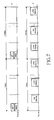
- Fig. 1 shows the configuration of a general Ethernet-PON for integrating broadcast and communication.
- the Ethernet-PON for integrating broadcast and communication includes an OLT (Optical Line Terminal) 100, a plurality of ONTs (Optical Network Terminals) 200-1 to 200-N, and a passive optical splitter 118, and further includes optical cables for connecting the OLT 100 with the ONTs 200-1 to 200-N.
- the OLT 100 is a subsystem positioned between a service node and users, which receives broadcast and communication signals transmitted from broadcast and communication providers, and combines them to an optical signal after electro-optical conversion, and then transmits the optical signal.
- the ONTs 200-1 to 200-N are user-side devices for transferring information received from the OLT 100 to users.
- the OLT 100 optically converts a broadcast signal received from a broadcast network through O/E and E/O converters 115 and 116, and then transmits the converted signal after optically amplifying it through an EDFA (Erbium Doped Fiber Amplifier) 117.
- the OLT 100 receives communication data from an IP (Internet Protocol) network through an IP router 111, and processes it into an optical signal through an E-PON OLT function processor 112, and then transmits it through a transmitter 113.
- the OLT 100 receives data from the ONTs 200-1 to 200-N, and transmits it to the IP network through the IP router 111.
- the ONTs 200-1 to 200-N receive broadcast signals through broadcast receivers 119-1 to 119-N, and transfer them to users through broadcast STBs (SetTop Box) 122-1 to 122-N.
- the ONTs 200-1 to 200-N receive communication data through receivers 120-1 to 120-N, and transfer it to users through E-PON ONT function processors 123-1 to 123-N.
- the ONTs 200-1 to 200-N receive communication data from users through the E-PON ONT function processors 123-1 to 123-N, and transmit it to the OLT 100 through burst-mode transmitters 121-1 to 121-N.
- the ONTs 200-1 to 200-N since all broadcast channels are transmitted to each of the ONTs 200-1 to 200-N, it is required for the ONTs 200-1 to 200-N to include a high spec, high cost optical receiver, which has high reception sensitivity and excellent noise characteristics, in order to receive the transmitted broadcast signals.
- TDM Time Division Multiplexing
- QoS Quality of Service
- an Ethernet-PON Passive Optical Network
- a TDM Time Division Multiplexing
- an OLT Optical Line Terminal
- IP Internet Protocol
- electro-optically converting and transmitting the frame a plurality of ONTs (Optical Network Terminals), each ONT receiving an optical signal from the OLT, photoelectrically converting the received signal, performing frame & time-slot demultiplexing on the converted signal to output entire received communication signals and broadcast/image information included in a time-slot assigned to the ONT to a corresponding user, and receiving
- an Ethernet-PON for integrating broadcast and communication based on a TDM scheme, comprising: an OLT for performing a switching operation on a plurality of digital broadcast/image data received from an external broadcast provider, according to respective broadcast/image selection information from users, performing time division multiplexing on the digital broadcast/image data to convert it into a broadcast/image signal, electro-optically converting the broadcast/image signal into a broadcast/image optical signal of ⁇ B , electro-optically converting communication data received through an IP network into a communication optical signal of ⁇ DOWN , coupling the broadcast/image optical signal of ⁇ B and the communication optical signal of ⁇ DOWN into a single signal, and transmitting the single signal; a plurality of ONTs, each ONT receiving an optical signal from the OLT, separating the received signal into the broadcast/image optical signal of ⁇ B and the communication optical signal of ⁇ DOWN , photoelectrically converting the two separated signals, performing time division demultiplexing on the converted broadcast
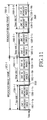
- Figs. 2A and 2B show the configuration of an Ethernet passive optical network (Ethernet-PON) for integrating broadcast and communication based on a TDM scheme, according to an embodiment of the present invention.
- Ethernet-PON Ethernet passive optical network
- the Ethernet-PON includes a single OLT, an optical splitter 216, and n ONTs.
- the n ONTs are assigned to n users, respectively. In other words, for each user, one ONT is connected to the network.
- the Ethernet-PON is configured as follows.
- the OLT 300 includes a broadcast/image channel selection switch 21, a broadcast/image time-slot multiplexer 22, a broadcast/image channel selection controller 23, an IP router 24, an E-PON OLT function processor 25, a synchronization controller 26, a frame multiplexer 27, an Ethernet time-slot matching buffer 28, an optical transmitter 29, an optical receiver 210, and a WDM coupler 211.
- the broadcast/image channel selection switch 21 performs a switching operation on MPEG (Motion Picture Experts Group) broadcast/image data.
- MPEG Motion Picture Experts Group
- the broadcast/image channel selection controller 23 receives respective channel selection information from the ONTs 400-1 to 400-16, and transfers a control signal to the broadcast/image channel selection switch 21 so as to allow the switch 21 to select their respective broadcast/image channels.
- the broadcast/image time-slot multiplexer 22 is connected to the broadcast/image channel selection switch 21 to multiplex the broadcast/image channels selected respectively by the subscribers into a single time-slot in a time division multiplexing (TDM) scheme.
- TDM time division multiplexing
- the IP router 24 routes communication data to an upper IP network or to the Ethernet-PON OLT function processor 25.
- the Ethernet-PON OLT function processor 25 performs Ethernet-PON OLT functions.
- the Ethernet time-slot matching buffer 28 stores communication data from the Ethernet-PON OLT function processor 25, which will be transmitted to the OLT, in order to match/couple it to the TDM (Time Division Multiplexed) broadcast/image signals.
- the frame multiplexer 27 multiplexes a broadcast/image signal from the broadcast/image time-slot multiplexer 22 and an Ethernet communication signal from the Ethernet time-slot matching buffer 28 into a single frame.
- the optical transmitter 29 transmits the frame-multiplexed signal after optically modulating it with a wavelength ⁇ DOWN .
- the optical receiver 210 receives an optical signal from the ONTs and converts it into an electrical signal.
- the WDM coupler 211 couples/splits transmission and reception wavelengths.
- each of the ONTs includes a WDM coupler 217, an optical transmitter 218, an optical transmitter 219, a frame/time-slot demultiplexer 220, an Ethernet-PON ONT function processor 221, and a broadcast/image adapter 222.
- the WDM coupler 217 couples and splits transmission and reception wavelengths.
- the optical transmitter 218 transmits upstream data to the OLT.
- the optical receiver 219 receives an optical signal of ⁇ DOWN from the OLT through the WDM coupler 217, and photoelectrically converts it.
- the frame/time-slot demultiplexer 220 separates the broadcast/image and Ethernet communication signals that have been multiplexed in a frame/time-slot multiplexing scheme.
- the Ethernet-PON ONT function processor 221 performs ONT functions.
- the broadcast/image adapter 222 recovers the separated broadcast/image signal into an original signal.
- Fig. 3 shows a first example of a frame and time-slots for Ethernet communication and broadcast/image signals, according to the present invention.
- a single frame 31 obtained by multiplexing broadcast/image signals and an Ethernet communication signal is divided into n time-slots 32-1, 32-2, ..., 32-n.
- the time-slots 32-1, 32-2, ..., 32-n are composed of broadcast/image sub-time-slots 32-1a, 32-2a, ..., 32-na and Ethernet sub-time-slots 32-1b, 32-2b, ..., 32-nb, respectively.
- the broadcast/image sub-time-slots 32-1a, 32-2a, ..., 32-na correspond to the subscribers, respectively.
- a broadcast/image sub-time-slot in an i-th time-slot is necessarily filled with only a broadcast/image signal selected by an i-th ONT, and it is left empty or filled with null data if there is no broadcast/image signal selected by the i-th ONT.
- communication data for every ONT may be positioned in the Ethernet sub-time-slots of all time-slots.
- a broadcast/image signal selected by the first ONT may be necessarily positioned in the broadcast/image sub-time-slot 32-1a of the first time-slot 32-1.
- An Ethernet communication signal of every ONT may be filled in the Ethernet sub-time-slot 32-1b of the first time-slot 32-1. The same is true for other time-slots 32-2, ..., 32-n.
- Fig. 4 shows a second example of a frame and time-slots for Ethernet communication and broadcast/image signals, according to the present invention.
- a single frame 41 according to the present invention obtained by multiplexing broadcast/image signals and an Ethernet communication signal, is composed of a broadcast/image frame 42 and an Ethernet communication frame 43.
- the broadcast/image frame 42 is composed of time-slots 44-1, 44-2, ..., 44-n, fixedly assigned to the ONTs, respectively.
- Downstream communication (from the OLT to the ONTs) is performed in the following manner.
- MPEG digital broadcast and image channels are inputted to the broadcast/image channel selection switch 21.
- Each subscriber (or ONT) assigns a broadcast/image channel he or she desires to watch through a remote controller, and a signal thereof is transferred, as broadcast/image channel selection information 226, from the corresponding ONT to the broadcast/image channel selection controller 23 via the Ethernet-PON.
- the broadcast channel selection controller 23 provides a control signal 21-2 to the broadcast/image channel selection switch 21, and controls the switch 21 based on the broadcast/image channel selection information 226 to switch to digital broadcast/image signals 214-1, 214, ..., 214-n the subscribers (or ONTs) desire to watch, respectively.
- the broadcast/image signals 214-1, 214-2, ..., 214-n are selected by the first, second, ..., n-th ONTs, respectively.
- the switched broadcast/image signals are inputted to the broadcast/image time-slot multiplexer 22 to be formed according to the time-slot configuration defined in Fig. 3.
- the frame and time-slot is configured as shown in Fig. 3 in the embodiments of the present invention.
- This frame and time-slot configuration is adopted only for illustrative purposes, and the present invention is not limited thereto, i.e., the present invention may also adopt the frame and time-slot configuration as shown in Fig. 4.
- the broadcast/image time-slot multiplexer 22 multiplexes broadcast/image signals inputted at a predetermined speed of R [b/s] in a time-slot multiplexing scheme, as denoted by "51" in Fig. 5, after converting it into a specific speed of 1.25 G/2k [b/s].
- This specific speed of 1.25 G/2k [b/s] is just an example, and the present invention is not limited thereto.
- the input speed of R [b/s] is 27M b/s in the case where the inputted signals are MPEG-TS streams.
- broadcast/image signals selected by the ONTs are positioned in the sub-time-slots uniquely assigned to the ONTs as defined in Fig. 3, respectively.
- An Ethernet communication signal transmitted from an upper level IP network is subjected to Ethernet-PON function processes at the Ethernet-PON function processor 25 after passing through the IP router 24.
- the communication signal is then inputted to the Ethernet time-slot matching buffer 28 so as to satisfy the Ethernet frame and time-slot definition as shown in Fig. 3.
- the Ethernet communication signal stored in the Ethernet time-slot matching buffer 28 is outputted only at the Ethernet sub-time-slots defined as shown in Fig. 3, so as to have a format as denoted by "52" in Fig. 5.
- the broadcast/image signal 51 outputted from the broadcast/image time-slot multiplexer 22 and the Ethernet communication signal 52 outputted from the Ethernet time-slot matching buffer 28 are frame-multiplexed by the frame multiplexer 27 as denoted by "53" in Fig. 5.
- the frame-multiplexed broadcast/image and Ethernet communication signal is electro-optically converted into an optical signal having a wavelength ⁇ DOWN at the optical transmitter 29, and then transmitted to the ONTs via the WDM coupler 211 and the 1 x n optical splitter 216.
- the downstream optical signal inputted to the ONT is received and photoelectrically converted by the optical receiver 219 after passing through the WDM coupler 217.
- the converted signal is inputted to the frame and time-slot demultiplexer 220 to be separated into an Ethernet communication signal and a broadcast/image signal selected by the ONT.
- This demultiplexing operation is performed in the following manner. For example, in the first ONT, broadcast/image channels 62 and 63 selected by the first ONT are separated through a switching signal as denoted by "61" in Fig. 6, since the channels 62 and 63 are positioned in the first time-slot of the frame.
- Ethernet communication signals 65-1 to 65-6 are separated through a switching signal as denoted by "64" in Fig. 6.
- the separated communication signal 223 (denoted by "72" in Fig. 7) is transmitted, as downstream communication data 227, to a terminal device such as a computer after passing through the ONT function processor 221.
- the separated broadcast/image channel 224 (denoted by "71" in Fig. 7) is converted into the original speed of R [b/s] (27 Mb/s in the case of MPEG-TS stream signals), which is then transferred, as a digital broadcast/image signal 228, to an MPEG decoder, etc.
- upstream communication (from the ONTs to the OLT) is performed in the following manner.
- Each subscriber produces broadcast/image channel selection data or information 226 for watching a broadcast/image channel and IP communication data 225 through a computer, etc.
- the produced data is optically modulated into an optical signal having a wavelength ⁇ UP at the optical transmitter 218.
- the converted optical signal is transmitted to the OLT via the WDM coupler 217 and the optical splitter 216.
- Upstream data signals transmitted from the ONTs are photoelectrically modulated at the optical receiver 210 after passing through the WDM coupler 211 in the OLT.
- the modulated upstream signal is transferred to the Ethernet-PON OLT function processor 25.
- the broadcast/image channel selection information 21-3 is transferred from the Ethernet-PON OLT function processor 25 to the broadcast/image channel selection controller 23, and the IP communication data is transferred to an upper level IP network through the IP router 24.
- Fig. 8 shows the configuration of an example of a hybrid Ethernet-PON, including a plurality of Ethernet-PONs, for integrating broadcast and communication based on a TDM scheme, according to the present invention.
- the hybrid Ethernet-PON for integrating broadcast and communication includes L OLTs and L x n ONTs, which operates in the following manner.
- a digital broadcast signal transmitted from an SO (Service Operator) or DMC (Digital Medical Center) 81 is separated into N MPEG digital broadcast channels at a digital broadcast channel separator 83.
- Each separated MPEG digital broadcast channel is split into L signals at a corresponding one of N splitters 87-1 to 87-N, which are transferred to L Ethernet-PON OLTs 89-1, 89-2, ..., 89-L, respectively.
- Digital image data transmitted from a digital image source 82 is separated into M MPEG digital image channels at a digital image channel separator 84. Each separated channel is split into L signals at a corresponding one of M splitters 88-1 to 88-M, which are transferred to the L Ethernet-PON OLTs 89-1, 89-2, ..., 89-L, respectively.
- IP network 85 Communication data transmitted from an IP network 85 is inputted to an IP router 86, through which it is routed to the L OLTs 89-1 to 89-L.
- the digital broadcast/image and communication data is transmitted to the ONTs 812-1 to 812-16 via an optical cable 810 and an optical splitter 811, as described above in detail with reference to Figs. 2A and 2B.
- Figs 9A and 9B show the configuration of an Ethernet-PON employing an optical receiver and an optical transmitter separately provided for broadcast/image signals, according to another embodiment of the present invention.
- the Ethernet-PON in this embodiment employs the optical receiver and transmitter separately provided for broadcast/image signals in order to secure a wide broadcast/image bandwidth.
- This embodiment is different from the embodiment of Figs. 2A and 2B in that an Ethernet communication signal and broadcast/image signals are separately subjected to electro-optical conversion at an OLT so as to be transmitted, and time division multiplexing is thus required only for the broadcast/image signals. There is also no need for this embodiment to perform frame multiplexing, etc.
- upstream and downstream Ethernet communication signals are all subjected to the operation of an Ethernet-PON ONT function processor 99 without being demultiplexed, whereas broadcast/image signals are subjected to time division demultiplexing and broadcast/image adaptation through a time division demultiplexer & broadcast/image adapter 98.
- a broadcast/image frame 1000-1 or 1000-2 as shown in Fig. 10 is composed of time-slots 1000-1-1 to 1000-1-16 or 1000-2-1 to 1000-2-16, respectively, for broadcast/image signals of the ONTs.
- the time-slots 1000-1-1 to 1000-1-16 or 1000-2-1 to 1000-2-16 are each composed of a plurality of sub-time-slots (two sub-time-slots in this embodiment) 1000-1-1a/b to 1000-1-16a/b or 1000-2-1a/b to 1000-2-16a/b for accommodating broadcast/image signals.
- the i-th time-slots are assigned to the i-th ONT, and only broadcast/image signals selected by the i-th ONT are necessarily positioned in the i-th time-slots. At least one sub-time-slot of the i-th time-slot is left empty or filled with null data if there is only one or no broadcast/image channel selected by the i-th ONT.
- the broadcast/image signal speed may be determined based on the number of broadcast/image signals required to be accommodated, etc.
- broadcast/image signals selected by the first ONT are necessarily positioned in the broadcast/image sub-time-slots 1000-1-1a/b or 1000-2-1a/b of the first time-slot 1000-1-1 or 1000-2-1.
- broadcast/image signals selected by the sixteenth ONT are necessarily positioned in the broadcast/image sub-time-slots 1000-1-16a/b or 1000-2-16a/b of the sixteenth time-slot 1000-1-16 or 1000-2-16. The same is true for other time-slots.
- Fig. 11 illustrates how desired broadcast/image time-slots are separated from time-division-multiplexed frames, according to said another embodiment of the present invention shown in Figs. 9A and 9B.
- time-slots assigned to the corresponding ONT may be selected through a switching signal as denoted by "1001".
- Fig. 12 illustrates a broadcast/image signal separated from the signal shown in Fig. 11 through the switching signal 1001.
- Broadcast/image channels corresponding respectively to the subscribers, selected at a broadcast/image channel selection switch 21 are inputted to a broadcast/image time division multiplexer 91.
- the selected signals are multiplexed in a TDM scheme according to the time-slot location definition as shown in Fig. 10.
- the broadcast/image signal speed is R [b/s]
- the TDM (Time Division multiplexed) broadcast/image signal speed is K [b/s].
- the TDM broadcast/image signal is optically modulated and transmitted to the ONTs.
- the transmitted signal is received by an optical receiver 97 in an ONT.
- the ONT must select a broadcast/image channel selected by it, since the received broadcast/image signal includes all broadcast/image channels selected by all the ONTs.
- a broadcast/image channel selected by the first ONT corresponding to the time-slots 1000-1-1 and 1000-2-1, is separated from broadcast/image data received by the first ONT, as shown in Fig. 12, through the switching signal 2000 of Fig. 11 at a time division demultiplexer & broadcast/image adapter 98 in the first ONT, since the received broadcast/image data includes all the broadcast/image channels selected by all the ONTs, as shown in Fig. 11.
- the separated broadcast/image signals are converted into an original data speed of R [b/s] at a broadcast/image adapter portion in the time division demultiplexer & broadcast/image adapter 98.
- the converted signals are transmitted to an MPEG decoder, etc.
- an Ethernet-PON for integrating broadcast and communication based on a TDM scheme has the following advantages. Since broadcast channels desired by users are selected at an OLT to be transmitted to ONTs, it is possible for the ONTs to use a low cost, low spec optical receiver for receiving broadcast signals, instead of an EDFA for a large amount of broadcast signals.
- broadcast information is transmitted through a communication data line in the Ethernet-PON, thereby enabling bi-directional broadcasting functions.
Abstract
Description
- The present invention relates to optical transmission, and more particularly to an Ethernet passive optical network (Ethernet-PON) for providing high-volume, high-speed data services and real-time broadcast/image services to subscribers.
- Data transfer rates above 100 Mb/s are required to efficiently provide high-volume, high-speed data services and real-time digital broadcast/image services to subscribers. However, it is impossible for current network systems including a cable modem or xDSL to provide the high-volume, high-speed data services and real-time digital broadcast/image services since the systems have transfer rates no more than 50 Mb/s. Thus, it has been required to study a high-speed transmission network capable of providing high-volume, high-speed data services and real-time digital broadcast/image services. An optical network has been proposed as such a high-speed transmission network, and, particularly, a passive optical network (PON) is attracting attention as a solution to economically implement the optical network.
- There are various PONs such as a PON based on ATM (ATM-PON), a PON based on WDM (WDM-PON) and a PON based on Ethernet (Ethernet-PON or EPON). An EPON-based FTTH (Fiber To The Home) system has been proposed and developed as a system capable of enabling high-speed optical transmission to general residences.
- In general, the Ethernet-PON has been developed basically in order to accommodate communication data signals. Data transmission in the Ethernet-PON is performed in such a manner that Gigabit Ethernet signals are transmitted at 1.25 Gb/s from an OLT to ONTs at a wavelength of 1550 nm, whereas Gigabit Ethernet signals are transmitted at 1.25 Gb/s from the ONTs to the OLT at a wavelength of 1310 nm. As a demand for broadcast services through the optical network increases, a need to allow the Ethernet-PON to also accommodate broadcast signals has been suggested. To meet the need, an overlay broadcast accommodation system has been proposed in which broadcast signals are transmitted to the ONTs through a different wavelength for broadcast signals from the wavelength for communication data, as shown in Fig. 1.
- Fig. 1 shows the configuration of a general Ethernet-PON for integrating broadcast and communication.
- As shown in this drawing, the Ethernet-PON for integrating broadcast and communication includes an OLT (Optical Line Terminal) 100, a plurality of ONTs (Optical Network Terminals) 200-1 to 200-N, and a passive
optical splitter 118, and further includes optical cables for connecting theOLT 100 with the ONTs 200-1 to 200-N. The OLT 100 is a subsystem positioned between a service node and users, which receives broadcast and communication signals transmitted from broadcast and communication providers, and combines them to an optical signal after electro-optical conversion, and then transmits the optical signal. The ONTs 200-1 to 200-N are user-side devices for transferring information received from the OLT 100 to users. - In more detail, the
OLT 100 optically converts a broadcast signal received from a broadcast network through O/E and E/O converters IP router 111, and processes it into an optical signal through an E-PONOLT function processor 112, and then transmits it through atransmitter 113. In addition, the OLT 100 receives data from the ONTs 200-1 to 200-N, and transmits it to the IP network through theIP router 111. - The ONTs 200-1 to 200-N receive broadcast signals through broadcast receivers 119-1 to 119-N, and transfer them to users through broadcast STBs (SetTop Box) 122-1 to 122-N. On the other hand, the ONTs 200-1 to 200-N receive communication data through receivers 120-1 to 120-N, and transfer it to users through E-PON ONT function processors 123-1 to 123-N. In addition, the ONTs 200-1 to 200-N receive communication data from users through the E-PON ONT function processors 123-1 to 123-N, and transmit it to the
OLT 100 through burst-mode transmitters 121-1 to 121-N. - In such a conventional Ethernet-PON system for accommodating broadcast signals, it is required to provide the EDFA 117, a high-priced optical amplifier for broadcast signal amplification, in order to transfer analog broadcast signals from the
OLT 100 to the ONTs 200-1 to 200-N. In addition, even when it accommodates only digital broadcast signals other than the analog broadcast signals, the E-PON system must be provided with the high-priced EDFA 117 if there are a large number of digital broadcast channels. - Further, since all broadcast channels are transmitted to each of the ONTs 200-1 to 200-N, it is required for the ONTs 200-1 to 200-N to include a high spec, high cost optical receiver, which has high reception sensitivity and excellent noise characteristics, in order to receive the transmitted broadcast signals.
- It is expected that future users will demand not only digital broadcast services but also high-quality, real-time digital image services. However, it is difficult for the conventional Ethernet-PON to accommodate the high-quality, real-time digital image signals.
- In addition, in the conventional Ethernet-PON, there has been no suggestion as to how to transmit specific broadcast information from the ONTs 200-1 to 200-N to the
OLT 100, and it is thus difficult to implement bi-directional broadcasting functions that will be required in the future. - Therefore, the present invention has been made in view of the above problems.
- It is the object of the present invention to provide an Ethernet-PON for integrating broadcast and communication based on a TDM (Time Division Multiplexing) scheme, which provides users with not only high-speed, high-volume communication data but also high-image-quality, real-time digital broadcast/image data.
- This object is solved by the subject matter of the independent claims.
- Preferred embodiments are defined in the dependent claims.
- It is an aspect of the present invention to provide an Ethernet-PON for integrating broadcast and communication based on a TDM scheme, wherein broadcast channels desired by users are selected at an OLT to be transmitted to ONTs, thereby allowing the ONTs to use a low cost, low spec optical receiver for receiving broadcast signals, instead of an EDFA for a large amount of broadcast signals.
- It is a further aspect of the present invention to provide an Ethernet-PON for integrating broadcast and communication based on a TDM scheme, which can ensure QoS (Quality of Service) in transmitting not only digital broadcast signals but also high-image-quality digital image signals that will be required by future users.
- It is yet another aspect of the present invention to provide an Ethernet-PON for integrating broadcast and communication based on a TDM scheme, in which broadcast information is transmitted through a communication data line in the Ethernet-PON, thereby enabling bi-directional broadcasting functions.
- In accordance with one aspect of the present invention, the above and other objects can be accomplished by the provision of an Ethernet-PON (Passive Optical Network) for integrating broadcast and communication based on a TDM (Time Division Multiplexing) scheme, comprising: an OLT (Optical Line Terminal) for performing a switching operation on a plurality of digital broadcast/image data received from an external broadcast provider, according to respective broadcast/image selection information from users, performing time division multiplexing on the digital broadcast/image data to convert it into a broadcast/image signal, frame-multiplexing the broadcast/image signal and communication data received through an IP (Internet Protocol) network into a single frame, and electro-optically converting and transmitting the frame; a plurality of ONTs (Optical Network Terminals), each ONT receiving an optical signal from the OLT, photoelectrically converting the received signal, performing frame & time-slot demultiplexing on the converted signal to output entire received communication signals and broadcast/image information included in a time-slot assigned to the ONT to a corresponding user, and receiving a communication signal and the broadcast/image selection information from the user to output them to the OLT; and an optical splitter for splitting a signal from the OLT into the plurality of ONTs, coupling signals from the plurality of ONTs, and transmitting the coupled signal to the OLT.
- In accordance with another aspect of the present invention, there is provided an Ethernet-PON for integrating broadcast and communication based on a TDM scheme, comprising: an OLT for performing a switching operation on a plurality of digital broadcast/image data received from an external broadcast provider, according to respective broadcast/image selection information from users, performing time division multiplexing on the digital broadcast/image data to convert it into a broadcast/image signal, electro-optically converting the broadcast/image signal into a broadcast/image optical signal of λB, electro-optically converting communication data received through an IP network into a communication optical signal of λDOWN, coupling the broadcast/image optical signal of λB and the communication optical signal of λDOWN into a single signal, and transmitting the single signal; a plurality of ONTs, each ONT receiving an optical signal from the OLT, separating the received signal into the broadcast/image optical signal of λB and the communication optical signal of λDOWN, photoelectrically converting the two separated signals, performing time division demultiplexing on the converted broadcast/image signal to convert it into broadcast/image information, outputting the broadcast/image information and the photoelectrically converted communication signal to a corresponding user, and receiving a communication signal and the broadcast/image selection information from the user to output them to the OLT; and an optical splitter for splitting a signal from the OLT into the plurality of ONTs, coupling signals from the plurality of ONTs, and transmitting the coupled signal to the OLT.
- The above features and other advantages of the present invention will be more clearly understood from the following detailed description taken in conjunction with the accompanying drawings, in which:
- Fig. 1 shows the configuration of a general Ethernet passive optical network (Ethernet-PON) for integrating broadcast and communication;
- Figs. 2A and 2B show the configuration of an Ethernet-PON for integrating broadcast and communication based on a TDM scheme, according to an embodiment of the present invention;
- Fig. 3 shows a first example of a frame and time-slots for Broadcast/image and Ethernet communication signals, according to the present invention;
- Fig. 4 shows a second example of a frame and time-slots for broadcast/image and Ethernet communication signals, according to the present invention;
- Fig. 5 illustrates a frame multiplexing procedure for broadcast/image and Ethernet communication signals, according to the present invention;
- Fig. 6 illustrates a frame demultiplexing procedure for a frame-multiplexed broadcast/image and Ethernet communication signal, according to the present invention;
- Fig. 7 illustrates frame-demultiplexed broadcast/image and Ethernet communication signals, according to the present invention;
- Fig. 8 shows the configuration of an example of a hybrid Ethernet-PON, including a plurality of Ethernet-PONs, for integrating broadcast and communication based on a TDM scheme, according to the present invention;
- Figs. 9A and 9B show the configuration of an Ethernet-PON employing an optical receiver and an optical transmitter separately provided for broadcast/image signals, according to another embodiment of the present invention;
- Fig. 10 illustrates time-slots for broadcast/image signals according to the embodiment of Figs. 9A and 9B;
- Fig. 11 illustrates time division demultiplexing on time-slots for broadcast/image signals, according to the embodiment of Figs. 9A and 9B; and
- Fig. 12 illustrates broadcast/image channels separated by the time division demultiplexing on the time-slots for broadcast/image signals, according to the embodiment of Figs. 9A and 9B.
-
- Now, preferred embodiments of the present invention will be described in detail with reference to the annexed drawings. In the drawings, the same or similar elements are denoted by the same reference numerals even though they are depicted in different drawings. In the following description, a detailed description of known functions and configurations incorporated herein will be omitted when it may make the subject matter of the present invention rather unclear.
- Figs. 2A and 2B show the configuration of an Ethernet passive optical network (Ethernet-PON) for integrating broadcast and communication based on a TDM scheme, according to an embodiment of the present invention.
- As shown in this drawing, the Ethernet-PON includes a single OLT, an
optical splitter 216, and n ONTs. The n ONTs are assigned to n users, respectively. In other words, for each user, one ONT is connected to the network. - In more detail, the Ethernet-PON according to the present invention is configured as follows. The OLT 300 includes a broadcast/image
channel selection switch 21, a broadcast/image time-slot multiplexer 22, a broadcast/imagechannel selection controller 23, anIP router 24, an E-PONOLT function processor 25, asynchronization controller 26, aframe multiplexer 27, an Ethernet time-slot matching buffer 28, anoptical transmitter 29, anoptical receiver 210, and aWDM coupler 211. The broadcast/imagechannel selection switch 21 performs a switching operation on MPEG (Motion Picture Experts Group) broadcast/image data. The broadcast/imagechannel selection controller 23 receives respective channel selection information from the ONTs 400-1 to 400-16, and transfers a control signal to the broadcast/imagechannel selection switch 21 so as to allow theswitch 21 to select their respective broadcast/image channels. The broadcast/image time-slot multiplexer 22 is connected to the broadcast/imagechannel selection switch 21 to multiplex the broadcast/image channels selected respectively by the subscribers into a single time-slot in a time division multiplexing (TDM) scheme. TheIP router 24 routes communication data to an upper IP network or to the Ethernet-PONOLT function processor 25. The Ethernet-PONOLT function processor 25 performs Ethernet-PON OLT functions. The Ethernet time-slot matching buffer 28 stores communication data from the Ethernet-PONOLT function processor 25, which will be transmitted to the OLT, in order to match/couple it to the TDM (Time Division Multiplexed) broadcast/image signals. Theframe multiplexer 27 multiplexes a broadcast/image signal from the broadcast/image time-slot multiplexer 22 and an Ethernet communication signal from the Ethernet time-slot matching buffer 28 into a single frame. Theoptical transmitter 29 transmits the frame-multiplexed signal after optically modulating it with a wavelength λDOWN. Theoptical receiver 210 receives an optical signal from the ONTs and converts it into an electrical signal. TheWDM coupler 211 couples/splits transmission and reception wavelengths. - On the other hand, each of the ONTs includes a
WDM coupler 217, anoptical transmitter 218, anoptical transmitter 219, a frame/time-slot demultiplexer 220, an Ethernet-PONONT function processor 221, and a broadcast/image adapter 222. TheWDM coupler 217 couples and splits transmission and reception wavelengths. Theoptical transmitter 218 transmits upstream data to the OLT. Theoptical receiver 219 receives an optical signal of λDOWN from the OLT through theWDM coupler 217, and photoelectrically converts it. The frame/time-slot demultiplexer 220 separates the broadcast/image and Ethernet communication signals that have been multiplexed in a frame/time-slot multiplexing scheme. The Ethernet-PONONT function processor 221 performs ONT functions. The broadcast/image adapter 222 recovers the separated broadcast/image signal into an original signal. - Fig. 3 shows a first example of a frame and time-slots for Ethernet communication and broadcast/image signals, according to the present invention.
- As shown in this drawing, a
single frame 31 obtained by multiplexing broadcast/image signals and an Ethernet communication signal is divided into n time-slots 32-1, 32-2, ..., 32-n. - The time-slots 32-1, 32-2, ..., 32-n are composed of broadcast/image sub-time-slots 32-1a, 32-2a, ..., 32-na and Ethernet sub-time-slots 32-1b, 32-2b, ..., 32-nb, respectively. The broadcast/image sub-time-slots 32-1a, 32-2a, ..., 32-na correspond to the subscribers, respectively.
- First, the broadcast/image sub-time-slots 32-1a, 32-2a, ..., 32-na are described as follows. A broadcast/image sub-time-slot in an i-th time-slot is necessarily filled with only a broadcast/image signal selected by an i-th ONT, and it is left empty or filled with null data if there is no broadcast/image signal selected by the i-th ONT. The broadcast/image signal speed is 1.25 G/2k [b/s] (k=0, 1, 2, ...) in the case where the Ethernet communication speed is 1.25 GbE.
- On the other hand, communication data for every ONT may be positioned in the Ethernet sub-time-slots of all time-slots. For example, only a broadcast/image signal selected by the first ONT may be necessarily positioned in the broadcast/image sub-time-slot 32-1a of the first time-slot 32-1. An Ethernet communication signal of every ONT may be filled in the Ethernet sub-time-slot 32-1b of the first time-slot 32-1. The same is true for other time-slots 32-2, ..., 32-n.
- Fig. 4 shows a second example of a frame and time-slots for Ethernet communication and broadcast/image signals, according to the present invention.
- As shown in this drawing, a single frame 41 according to the present invention, obtained by multiplexing broadcast/image signals and an Ethernet communication signal, is composed of a broadcast/
image frame 42 and anEthernet communication frame 43. The broadcast/image frame 42 is composed of time-slots 44-1, 44-2, ..., 44-n, fixedly assigned to the ONTs, respectively. - There may be various frame and time-slot definitions according to the number of broadcast/image channels selected by users.
- With reference to the frame and time-slot definition as shown in Figs. 3 and 4, a description will now be given of the operation of an Ethernet-PON for integrating broadcast and communication based on a TDM scheme, according to the present invention.
- Downstream communication (from the OLT to the ONTs) is performed in the following manner.
- As shown in Figs. 2A and 2B, first, MPEG digital broadcast and image channels are inputted to the broadcast/image
channel selection switch 21. Each subscriber (or ONT) assigns a broadcast/image channel he or she desires to watch through a remote controller, and a signal thereof is transferred, as broadcast/imagechannel selection information 226, from the corresponding ONT to the broadcast/imagechannel selection controller 23 via the Ethernet-PON. - The broadcast
channel selection controller 23 provides a control signal 21-2 to the broadcast/imagechannel selection switch 21, and controls theswitch 21 based on the broadcast/imagechannel selection information 226 to switch to digital broadcast/image signals 214-1, 214, ..., 214-n the subscribers (or ONTs) desire to watch, respectively. Here, the broadcast/image signals 214-1, 214-2, ..., 214-n are selected by the first, second, ..., n-th ONTs, respectively. - The switched broadcast/image signals are inputted to the broadcast/image time-
slot multiplexer 22 to be formed according to the time-slot configuration defined in Fig. 3. The frame and time-slot is configured as shown in Fig. 3 in the embodiments of the present invention. This frame and time-slot configuration is adopted only for illustrative purposes, and the present invention is not limited thereto, i.e., the present invention may also adopt the frame and time-slot configuration as shown in Fig. 4. - The broadcast/image time-
slot multiplexer 22 multiplexes broadcast/image signals inputted at a predetermined speed of R [b/s] in a time-slot multiplexing scheme, as denoted by "51" in Fig. 5, after converting it into a specific speed of 1.25 G/2k [b/s]. This specific speed of 1.25 G/2k [b/s] is just an example, and the present invention is not limited thereto. The input speed of R [b/s] is 27M b/s in the case where the inputted signals are MPEG-TS streams. As denoted by "51" in Fig. 5, broadcast/image signals selected by the ONTs are positioned in the sub-time-slots uniquely assigned to the ONTs as defined in Fig. 3, respectively. - An Ethernet communication signal transmitted from an upper level IP network is subjected to Ethernet-PON function processes at the Ethernet-
PON function processor 25 after passing through theIP router 24. The communication signal is then inputted to the Ethernet time-slot matching buffer 28 so as to satisfy the Ethernet frame and time-slot definition as shown in Fig. 3. - The Ethernet communication signal stored in the Ethernet time-
slot matching buffer 28 is outputted only at the Ethernet sub-time-slots defined as shown in Fig. 3, so as to have a format as denoted by "52" in Fig. 5. - The broadcast/
image signal 51 outputted from the broadcast/image time-slot multiplexer 22 and theEthernet communication signal 52 outputted from the Ethernet time-slot matching buffer 28 are frame-multiplexed by theframe multiplexer 27 as denoted by "53" in Fig. 5. - The frame-multiplexed broadcast/image and Ethernet communication signal is electro-optically converted into an optical signal having a wavelength λDOWN at the
optical transmitter 29, and then transmitted to the ONTs via theWDM coupler 211 and the 1 x noptical splitter 216. - The downstream optical signal inputted to the ONT is received and photoelectrically converted by the
optical receiver 219 after passing through theWDM coupler 217. - The converted signal is inputted to the frame and time-
slot demultiplexer 220 to be separated into an Ethernet communication signal and a broadcast/image signal selected by the ONT. This demultiplexing operation is performed in the following manner. For example, in the first ONT, broadcast/image channels channels - The separated communication signal 223 (denoted by "72" in Fig. 7) is transmitted, as
downstream communication data 227, to a terminal device such as a computer after passing through theONT function processor 221. - At the broadcast/
image adapter 222, the separated broadcast/image channel 224 (denoted by "71" in Fig. 7) is converted into the original speed of R [b/s] (27 Mb/s in the case of MPEG-TS stream signals), which is then transferred, as a digital broadcast/image signal 228, to an MPEG decoder, etc. - Next, upstream communication (from the ONTs to the OLT) is performed in the following manner. Each subscriber produces broadcast/image channel selection data or
information 226 for watching a broadcast/image channel andIP communication data 225 through a computer, etc. - After overcoming problems such as data collision through the E-PON
ONT function processor 221, the produced data is optically modulated into an optical signal having a wavelength λUP at theoptical transmitter 218. The converted optical signal is transmitted to the OLT via theWDM coupler 217 and theoptical splitter 216. - Upstream data signals transmitted from the ONTs are photoelectrically modulated at the
optical receiver 210 after passing through theWDM coupler 211 in the OLT. - The modulated upstream signal is transferred to the Ethernet-PON
OLT function processor 25. Of the data contained in this transferred signal, the broadcast/image channel selection information 21-3 is transferred from the Ethernet-PONOLT function processor 25 to the broadcast/imagechannel selection controller 23, and the IP communication data is transferred to an upper level IP network through theIP router 24. - Fig. 8 shows the configuration of an example of a hybrid Ethernet-PON, including a plurality of Ethernet-PONs, for integrating broadcast and communication based on a TDM scheme, according to the present invention.
- As shown in Fig. 8, the hybrid Ethernet-PON for integrating broadcast and communication includes L OLTs and L x n ONTs, which operates in the following manner.
- A digital broadcast signal transmitted from an SO (Service Operator) or DMC (Digital Medical Center) 81 is separated into N MPEG digital broadcast channels at a digital
broadcast channel separator 83. - Each separated MPEG digital broadcast channel is split into L signals at a corresponding one of N splitters 87-1 to 87-N, which are transferred to L Ethernet-PON OLTs 89-1, 89-2, ..., 89-L, respectively.
- Digital image data transmitted from a
digital image source 82 is separated into M MPEG digital image channels at a digitalimage channel separator 84. Each separated channel is split into L signals at a corresponding one of M splitters 88-1 to 88-M, which are transferred to the L Ethernet-PON OLTs 89-1, 89-2, ..., 89-L, respectively. - Communication data transmitted from an
IP network 85 is inputted to anIP router 86, through which it is routed to the L OLTs 89-1 to 89-L. - After being received by the OLTs 89-1, 89-2, ..., 89-L, the digital broadcast/image and communication data is transmitted to the ONTs 812-1 to 812-16 via an
optical cable 810 and anoptical splitter 811, as described above in detail with reference to Figs. 2A and 2B. - Figs 9A and 9B show the configuration of an Ethernet-PON employing an optical receiver and an optical transmitter separately provided for broadcast/image signals, according to another embodiment of the present invention.
- As shown in this drawing, the Ethernet-PON in this embodiment employs the optical receiver and transmitter separately provided for broadcast/image signals in order to secure a wide broadcast/image bandwidth.
- This embodiment is different from the embodiment of Figs. 2A and 2B in that an Ethernet communication signal and broadcast/image signals are separately subjected to electro-optical conversion at an OLT so as to be transmitted, and time division multiplexing is thus required only for the broadcast/image signals. There is also no need for this embodiment to perform frame multiplexing, etc.
- Accordingly, in the ONT, upstream and downstream Ethernet communication signals are all subjected to the operation of an Ethernet-PON
ONT function processor 99 without being demultiplexed, whereas broadcast/image signals are subjected to time division demultiplexing and broadcast/image adaptation through a time division demultiplexer & broadcast/image adapter 98. - In this embodiment, only time-slots, respectively, for the ONTs' broadcast/image signals are included in each frame as shown in Fig. 10, since only the broadcast/image signals are subjected to the time division multiplexing.
- In other words, a broadcast/image frame 1000-1 or 1000-2 as shown in Fig. 10 is composed of time-slots 1000-1-1 to 1000-1-16 or 1000-2-1 to 1000-2-16, respectively, for broadcast/image signals of the ONTs. The time-slots 1000-1-1 to 1000-1-16 or 1000-2-1 to 1000-2-16 are each composed of a plurality of sub-time-slots (two sub-time-slots in this embodiment) 1000-1-1a/b to 1000-1-16a/b or 1000-2-1a/b to 1000-2-16a/b for accommodating broadcast/image signals.
- The i-th time-slots are assigned to the i-th ONT, and only broadcast/image signals selected by the i-th ONT are necessarily positioned in the i-th time-slots. At least one sub-time-slot of the i-th time-slot is left empty or filled with null data if there is only one or no broadcast/image channel selected by the i-th ONT. Here, the broadcast/image signal speed may be determined based on the number of broadcast/image signals required to be accommodated, etc.
- For example, only broadcast/image signals selected by the first ONT are necessarily positioned in the broadcast/image sub-time-slots 1000-1-1a/b or 1000-2-1a/b of the first time-slot 1000-1-1 or 1000-2-1. Likewise, only broadcast/image signals selected by the sixteenth ONT are necessarily positioned in the broadcast/image sub-time-slots 1000-1-16a/b or 1000-2-16a/b of the sixteenth time-slot 1000-1-16 or 1000-2-16. The same is true for other time-slots.
- Fig. 11 illustrates how desired broadcast/image time-slots are separated from time-division-multiplexed frames, according to said another embodiment of the present invention shown in Figs. 9A and 9B. As shown in this drawing, time-slots assigned to the corresponding ONT may be selected through a switching signal as denoted by "1001". Fig. 12 illustrates a broadcast/image signal separated from the signal shown in Fig. 11 through the switching signal 1001.
- The operation of the Ethernet-PON in Figs. 9A and 9B will now be described with reference to Figs. 10 to 12.
- Broadcast/image channels, corresponding respectively to the subscribers, selected at a broadcast/image
channel selection switch 21 are inputted to a broadcast/imagetime division multiplexer 91. At thismultiplexer 91, the selected signals are multiplexed in a TDM scheme according to the time-slot location definition as shown in Fig. 10. Here, the broadcast/image signal speed is R [b/s], and the TDM (Time Division multiplexed) broadcast/image signal speed is K [b/s]. - Through an
optical transmitter 92, the TDM broadcast/image signal is optically modulated and transmitted to the ONTs. The transmitted signal is received by anoptical receiver 97 in an ONT. - The ONT must select a broadcast/image channel selected by it, since the received broadcast/image signal includes all broadcast/image channels selected by all the ONTs. For example, a broadcast/image channel selected by the first ONT, corresponding to the time-slots 1000-1-1 and 1000-2-1, is separated from broadcast/image data received by the first ONT, as shown in Fig. 12, through the
switching signal 2000 of Fig. 11 at a time division demultiplexer & broadcast/image adapter 98 in the first ONT, since the received broadcast/image data includes all the broadcast/image channels selected by all the ONTs, as shown in Fig. 11. The separated broadcast/image signals are converted into an original data speed of R [b/s] at a broadcast/image adapter portion in the time division demultiplexer & broadcast/image adapter 98. The converted signals are transmitted to an MPEG decoder, etc. - As apparent from the above description, an Ethernet-PON for integrating broadcast and communication based on a TDM scheme according to the present invention has the following advantages. Since broadcast channels desired by users are selected at an OLT to be transmitted to ONTs, it is possible for the ONTs to use a low cost, low spec optical receiver for receiving broadcast signals, instead of an EDFA for a large amount of broadcast signals.
- In addition, it is possible to ensure QoS (Quality of Service) in transmitting not only digital broadcast signals but also high-image-quality digital image signals that will be required by future users.
- Further, broadcast information is transmitted through a communication data line in the Ethernet-PON, thereby enabling bi-directional broadcasting functions.
- Although the preferred embodiments of the present invention have been disclosed for illustrative purposes, those skilled in the art will appreciate that various modifications, additions and substitutions are possible, without departing from the scope of the invention as disclosed in the accompanying claims.
Claims (14)
- An Ethernet passive optical network for integrating broadcast and communication based on a time division multiplexing scheme, comprising:an optical line terminal for performing a switching operation on a plurality of digital broadcast/image data received from an external broadcast provider, according to respective broadcast/image selection information from users, performing time division multiplexing on the digital broadcast/image data to convert it into a broadcast/image signal, frame-multiplexing the broadcast/image signal and communication data received through an internet protocol network into a single frame, and electro-optically converting and transmitting the frame;a plurality of optical network terminals, each optical network terminal receiving an optical signal from the optical line terminal, photoelectrically converting the received signal, performing frame & time-slot demultiplexing on the converted signal to output entire received communication signals and broadcast/image information included in a time-slot assigned to the optical network terminal to a corresponding user, and receiving a communication signal and the broadcast/image selection information from the user to output them to the optical line terminal; andan optical splitter for splitting a signal from the optical line terminal into the plurality of optical network terminals, coupling signals from the plurality of optical network terminals, and transmitting the coupled signal to the optical line terminal.
- The Ethernet passive optical network according to claim 1, wherein the optical line terminal includes:a broadcast/image channel selection switch for receiving external MPEG broadcast and image data, and switching and outputting it;a broadcast/image time-slot multiplexer for assigning broadcast/image channels, outputted from the broadcast/image channel selection switch, to time-slots assigned respectively to the users so as to multiplex the channels;an Ethernet passive optical network optical line terminal function processor for performing Ethernet passive optical network optical line terminal functions;an internet protocol router for routing a communication signal to an upper level internet protocol network or to the Ethernet passive optical network optical line terminal function processor;an Ethernet time-slot matching buffer for storing the communication data from the Ethernet passive optical network optical line terminal function processor, which will be transmitted to the optical line terminal, in order to match/couple it to the time-slot-multiplexed broadcast/image signal outputted from the time-slot multiplexer;a frame multiplexer for multiplexing the time-slot-multiplexed broadcast/image signal from the broadcast/image time-slot multiplexer and the communication signal stored in the Ethernet time-slot matching buffer into a single frame;a first optical transmitter for optically modulating a frame-multiplexed signal outputted from the frame multiplexer, and transmitting the modulated signal as an optical signal of λDOWN; anda first optical receiver for receiving an optical signal from the optical network terminals and converting it into an electrical signal.
- The Ethernet passive optical network according to claim 1 or 2, wherein each of the plurality of optical network terminals includes:a second optical receiver for receiving the signal transmitted as the optical signal of λDOWN from the optical line terminal, and photoelectrically converting it;a second optical transmitter for electro-optically converting upstream data and transmitting it to the optical line terminal;a frame/time-slot demultiplexer for separating the frame/time-slot-multiplexed broadcast/image and communication signals;an Ethernet passive optical network optical network terminal function processor for receiving the communication signal from the frame/time-slot demultiplexer, and performing optical network terminal functions on it; anda broadcast/image adapter for recovering a time-slot-format broadcast/image signal, separated by the frame/time-slot demultiplexer, into an original signal.
- The Ethernet passive optical network according to any one of claims 1 to 3, wherein the single frame obtained by multiplexing the broadcast/image signal and the communication signal is divided into a predetermined number of time-slots, and each of the time-slots includes a broadcast/image sub-time-slot for containing a broadcast/image signal and an Ethernet sub-time-slot for containing a communication signal.
- The Ethernet passive optical network according to claim 4, wherein the broadcast/image sub-time-slot contains a broadcast/image signal selected by one of the optical network terminals corresponding to said time-slot's order, and it is left empty or filled with null data if there is no broadcast/image signal selected by the optical line terminal.
- The Ethernet passive optical network according to claim 4, wherein the Ethernet sub-time-slot may contain communication data of every optical network terminal.
- The Ethernet passive optical network according to any one of claims 1 to 3, wherein the single frame obtained by multiplexing the broadcast/image signal and the communication signal is divided into a sub-frame for broadcast/image signals and a sub-frame for Ethernet communication signals, and the sub-frame for broadcast/image signals includes broadcast/image time-slots, respectively, for containing broadcast/image signals of the optical network terminals.
- The Ethernet passive optical network according to claim 7, wherein the broadcast/image time-slot contains a broadcast/image signal selected by one of the optical network terminals corresponding to said time-slot's order, and it is left empty or filled with null data if there is no broadcast/image signal selected by the optical network terminal.
- The Ethernet passive optical network according to claim 7, wherein the sub-frame for Ethernet communication signals may contain communication data of every optical network terminal.
- An Ethernet passive optical network for integrating broadcast and communication based on a time division multiplexing scheme, comprising:an optical line terminal for performing a switching operation on a plurality of digital broadcast/image data received from an external broadcast provider, according to respective broadcast/image selection information from users, performing time division multiplexing on the digital broadcast/image data to convert it into a broadcast/image signal, electro-optically converting the broadcast/image signal into a broadcast/image optical signal of λB, electro-optically converting communication data received through an internet protocol network into a communication optical signal of λDOWN, coupling the broadcast/image optical signal of λB and the communication optical signal of λDOWN into a single signal, and transmitting the single signal;a plurality of optical network terminals, each optical line terminal receiving an optical signal from the optical line terminal, separating the received signal into the broadcast/image optical signal of λB and the communication optical signal of λDOWN, photoelectrically converting the two separated signals, performing time division demultiplexing on the converted broadcast/image signal to convert it into broadcast/image information, outputting the broadcast/image information and the photoelectrically converted communication signal to a corresponding user, and receiving a communication signal and the broadcast/image selection information from the user to output them to the optical line terminal; andan optical splitter for splitting a signal from the optical line terminal into the plurality of optical network terminals, coupling signals from the plurality of optical network terminals, and transmitting the coupled signal to the optical line terminal.
- The Ethernet passive optical network according to claim 10, wherein the optical line terminal includes:a broadcast/image channel selection switch for receiving external MPEG broadcast and image data, and switching and outputting it;a time division multiplexer for assigning broadcast/image channels, outputted from the broadcast/image channel selection switch, to time-slots assigned respectively to the users so as to multiplex the channels in a time division multiplexing scheme;a first optical transmitter for optically modulating the time-division-multiplexed broadcast/image signal;an Ethernet passive optical network optical line terminal function processor for performing Ethernet passive optical network optical line terminal functions;an internet protocol router for routing communication data to an upper level internet protocol network or to the Ethernet passive optical network optical line terminal function processor;a second optical transmitter for optically modulating communication data to be transmitted to the plurality of optical network terminals;a first optical receiver for receiving an optical signal from the plurality of optical network terminals, converting it into an electrical signal, and transferring the converted signal to the Ethernet passive optical network optical line terminal function processor;a broadcast/image channel selection controller for receiving the broadcast/image selection information from the plurality of optical network terminals through the Ethernet passive optical network optical line terminal function processor, and transferring a control signal to the broadcast/image channel selection switch to allow the switch to select broadcast/image channels corresponding respectively to the plurality of optical network terminals; anda first wavelength division multiplexing coupler for coupling the optically modulated communication signal of λDOWN and the optically modulated broadcast/image signal of λB, and outputting the coupled signal.
- The Ethernet passive optical network according to claim 10 or 11, wherein each of the plurality of optical network terminals includes:a second time division multiplexing coupler for separating an optical signal received from the optical line terminal into a communication signal of λDOWN and a broadcast/image signal of λB;a second optical receiver for receiving the separated communication signal of λDOWN, and converting it into an electrical signal;a third optical receiver for receiving the separated broadcast/image signal of λB, and converting it into an electrical signal;an Ethernet passive optical network optical network terminal function processor, connected to the second optical receiver, for performing optical network terminal functions;a third optical transmitter for receiving broadcast/image selection information and a communication signal to be transmitted to the optical line terminal from a corresponding user through the Ethernet passive optical network optical network terminal function processor, and transmitting them as an optical signal λUP; anda time division demultiplexer & broadcast/image adapter for receiving the broadcast/image signal converted into the electrical signal, performing time division demultiplexing on the received signal, and recovering a time-slot-format broadcast/image signal, obtained through the time division demultiplexing, into an original signal.
- The Ethernet passive optical network according to any one of claims 10 to 12, wherein the time-division-multiplexed broadcast/image signal includes time-slots for broadcast/image signals corresponding respectively to the plurality of optical network terminals, and each of the time-slots includes a predetermined number of sub-time-slots for accommodating the same predetermined number of broadcast/image signals.
- A method for integrating broadcast and communication based on a time division multiplexing scheme in an Ethernet passive optical network according to one of claims 1 to 13.
Applications Claiming Priority (2)
| Application Number | Priority Date | Filing Date | Title |
|---|---|---|---|
| KR2003067087 | 2003-09-26 | ||
| KR1020030067087A KR100594075B1 (en) | 2003-09-26 | 2003-09-26 | Ethernet Passive Optical Network for Convergence of Broadcasting and Telecommunication By Using Time Dividing Multiplex |
Publications (3)
| Publication Number | Publication Date |
|---|---|
| EP1519616A2 true EP1519616A2 (en) | 2005-03-30 |
| EP1519616A3 EP1519616A3 (en) | 2007-10-24 |
| EP1519616B1 EP1519616B1 (en) | 2013-09-18 |
Family
ID=34192276
Family Applications (1)
| Application Number | Title | Priority Date | Filing Date |
|---|---|---|---|
| EP04013477.7A Expired - Fee Related EP1519616B1 (en) | 2003-09-26 | 2004-06-08 | Ethernet passive optical network integrating image broadcast and data communication based on time division multiplexing |
Country Status (5)
| Country | Link |
|---|---|
| US (1) | US7382982B2 (en) |
| EP (1) | EP1519616B1 (en) |
| JP (1) | JP4012532B2 (en) |
| KR (1) | KR100594075B1 (en) |
| CN (1) | CN1330142C (en) |
Cited By (6)
| Publication number | Priority date | Publication date | Assignee | Title |
|---|---|---|---|---|
| WO2006131099A1 (en) * | 2005-06-06 | 2006-12-14 | Adva Ag Optical Networking | Method and time-division multiplexing/demultiplexing unit for data transmission using time-division multiplexing, particularly for bandwidth-optimized data transmission of ip traffic with broadcast and multicast components in a wdm system |
| WO2008134961A1 (en) * | 2007-04-30 | 2008-11-13 | Huawei Technologies Co., Ltd. | Apparatus and method for estimating a passive optical network model |
| CN1863013B (en) * | 2005-12-28 | 2010-05-05 | 华为技术有限公司 | Network terminal apparatus in passive light network and data processing method thereof |
| US11350061B1 (en) * | 2021-11-11 | 2022-05-31 | Frontier Communications Holdings, Llc | Systems and methods for collecting information regarding optical connections in a fiber distribution hub of a passive optical network |
| US11356177B1 (en) | 2021-11-11 | 2022-06-07 | Frontier Communications Holdings, Llc | Systems and methods for mapping optical connections in a fiber distribution hub of a passive optical network |
| US11391894B1 (en) | 2021-11-11 | 2022-07-19 | Frontier Communications Holdings, Llc | Passive optical couplers having passive optical activity indicators and methods of operating the same |
Families Citing this family (30)
| Publication number | Priority date | Publication date | Assignee | Title |
|---|---|---|---|---|
| EP1271825A1 (en) * | 2001-06-25 | 2003-01-02 | Lucent Technologies Inc. | Method and system for multiplexed optical information transport |
| KR100582550B1 (en) * | 2004-02-11 | 2006-05-22 | 한국전자통신연구원 | System for servicing broadcasting data in Passive Optical Network and Method thereof |
| KR100640475B1 (en) * | 2004-07-22 | 2006-10-30 | 삼성전자주식회사 | Telecommunication Broadcating Multiplexer and Demultiplexer for Using Integrating System of Broadcasting and Telecommunication |
| US20060171714A1 (en) * | 2005-02-02 | 2006-08-03 | Calix Networks, Inc. | Electrically shared passive optical network |
| KR100703379B1 (en) * | 2005-02-16 | 2007-04-03 | 삼성전자주식회사 | Wireless transmitting/receiving apparatus |
| JP4687332B2 (en) * | 2005-08-25 | 2011-05-25 | 日本電気株式会社 | Optical access network center side device and optical access network data signal transmission method |
| US8600238B2 (en) * | 2005-11-01 | 2013-12-03 | Technology Advancement Group, Inc. | Method and system for bi-directional communication over a single optical fiber |
| US7840138B2 (en) * | 2005-11-01 | 2010-11-23 | Technology Advancement Group, Inc. | Method and system for bi-directional communication over a single optical fiber |
| JP4634290B2 (en) * | 2005-11-29 | 2011-02-16 | 富士通株式会社 | Transmission equipment |
| KR100723874B1 (en) * | 2005-12-09 | 2007-05-31 | 한국전자통신연구원 | Tdma passive optical network olt system for broadcast service |
| EP1978654B1 (en) * | 2006-01-18 | 2014-01-08 | Huawei Technologies Co., Ltd. | A method for mapping the service stream to the service transmission channel, system and optical network terminator thereof |
| US20070211755A1 (en) * | 2006-03-10 | 2007-09-13 | Siemens Aktiengesellschaft | Communications network and method of increasing bandwidth in a cable network |
| US7561801B2 (en) * | 2006-03-31 | 2009-07-14 | Applied Micro Circuits Corporation | Optical transceiver with electrical ring distribution interface |
| CN1976477B (en) * | 2006-12-11 | 2011-12-28 | 中兴通讯股份有限公司 | Mobile multi-media broadcasting data transmitting method |
| US7970281B2 (en) * | 2007-01-26 | 2011-06-28 | Fujitsu Limited | System and method for managing different transmission architectures in a passive optical network |
| JP4823110B2 (en) * | 2007-03-15 | 2011-11-24 | 富士通株式会社 | Passive optical network system and data transmission method in passive optical network |
| US8059962B2 (en) * | 2007-05-30 | 2011-11-15 | Futurewei Technologies, Inc. | Interleaving for 10G GPON |
| US20090052901A1 (en) * | 2007-08-20 | 2009-02-26 | Knology, Inc. | Hybrid fiber coax (hfc) circuit |
| US8086104B2 (en) * | 2008-02-15 | 2011-12-27 | Alcatel Lucent | System, method and computer readable medium for providing dual rate transmission on a gigabit passive optical network |
| CN102026047A (en) * | 2009-09-10 | 2011-04-20 | 华为技术有限公司 | Method, device and system for transmitting reset signals and rate indication signals |
| CN102546017A (en) * | 2010-12-14 | 2012-07-04 | 大屯有线电视股份有限公司 | Time-division multiplexing (TDM) optical fiber network system and method thereof |
| WO2013185111A2 (en) | 2012-06-07 | 2013-12-12 | Apple Inc. | Methods and apparatus for synchronization among integrated circuits within a wireless network |
| US9979505B2 (en) * | 2012-09-10 | 2018-05-22 | Tellabs Enterprise, Inc. | Delivery of GPON technology |
| EP2948858B1 (en) * | 2013-03-15 | 2018-06-06 | Apple Inc. | Method and apparatus for multi-drop digital bus |
| US9602311B2 (en) * | 2014-02-06 | 2017-03-21 | The Board Of Trustees Of The Leland Stanford Junior University | Dual-mode network |
| US9811991B2 (en) * | 2014-06-27 | 2017-11-07 | Harman International Industries, Incorporated | Do-not-disturb system and apparatus |
| US10250353B2 (en) | 2014-11-10 | 2019-04-02 | Perfectvision Manufacturing, Inc. | Electromagnetic signal transport and distribution systems |
| US9806844B2 (en) * | 2014-11-10 | 2017-10-31 | Perfectvision Manufacturing, Inc. | Electromagnetic signal transport and distribution system |
| US10085224B2 (en) | 2014-11-19 | 2018-09-25 | Apple Inc. | Methods and apparatus for synchronization of media playback within a wireless network |
| CN104486695B (en) * | 2014-12-03 | 2018-01-12 | 中国航空工业集团公司第六三一研究所 | A kind of airborne all optical networks structure of OWDM |
Citations (3)
| Publication number | Priority date | Publication date | Assignee | Title |
|---|---|---|---|---|
| US5694234A (en) * | 1994-10-20 | 1997-12-02 | Lucent Technologies Inc. | Wavelength division multiplexing passive optical network including broadcast overlay |
| WO2002045308A1 (en) * | 2000-11-17 | 2002-06-06 | Alloptic, Inc. | Point-to-multipoint passive optical network that utilizes variable-length packets |
| WO2003005156A2 (en) * | 2001-07-05 | 2003-01-16 | Broadcom Corporation | System, method, and computer program product for managing communications in ethernet-based fiber optic tdma networks |
Family Cites Families (22)
| Publication number | Priority date | Publication date | Assignee | Title |
|---|---|---|---|---|
| DE3045875A1 (en) * | 1980-12-05 | 1982-09-09 | Licentia Patent-Verwaltungs-Gmbh, 6000 Frankfurt | SERVICE-INTEGRATED, DIGITAL TRANSMISSION SYSTEM |
| US4994909A (en) * | 1989-05-04 | 1991-02-19 | Northern Telecom Limited | Video signal distribution system |
| US5150247A (en) * | 1989-10-30 | 1992-09-22 | Broadband Technologies, Inc. | Fiber optic telecommunication system employing continuous downlink, burst uplink transmission format with preset uplink guard band |
| US5576874A (en) * | 1991-07-31 | 1996-11-19 | Alcatel Network Systems, Inc. | Optical distribution shelf for a remote terminal of an optical fiber telecommunications network |
| DE4417771A1 (en) * | 1994-05-20 | 1995-11-23 | Siemens Ag | Optical TDM / TDMA system with increased range |
| DE69727660T2 (en) * | 1996-03-18 | 2004-12-23 | General Instrument Corporation | DYNAMIC BANDWIDTH ASSIGNMENT FOR A COMMUNICATION NETWORK |
| GB9704587D0 (en) * | 1997-03-05 | 1997-04-23 | Fujitsu Ltd | Wavelength-division multiplexing in passive optical networks |
| DE19727547A1 (en) * | 1997-06-28 | 1999-01-07 | Bosch Gmbh Robert | Method for signal transmission in a network |
| US6684031B1 (en) * | 1998-06-18 | 2004-01-27 | Lucent Technologies Inc. | Ethernet fiber access communications system |
| CN1244751A (en) | 1998-08-06 | 2000-02-16 | 深圳市华为技术有限公司 | Passive optical fiber network system |
| US6796555B1 (en) * | 1999-07-19 | 2004-09-28 | Lucent Technologies Inc. | Centralized video controller for controlling distribution of video signals |
| US6498667B1 (en) * | 1999-09-10 | 2002-12-24 | Quantum Bridge Communications, Inc. | Method and system for packet transmission over passive optical network |
| US6778550B1 (en) * | 2000-02-29 | 2004-08-17 | Lucent Technologies Inc. | Method and apparatus for TDM/TDMA communications |
| US7212540B2 (en) * | 2001-04-05 | 2007-05-01 | Nortel Networks Limited | Time slot scheduling for shared-medium communications networks |
| JP3636679B2 (en) | 2001-07-03 | 2005-04-06 | 松下電器産業株式会社 | Content distribution method and terminal management server device |
| US6804256B2 (en) * | 2001-07-24 | 2004-10-12 | Glory Telecommunications Co., Ltd. | Automatic bandwidth adjustment in a passive optical network |
| JP2003092583A (en) | 2001-09-19 | 2003-03-28 | Fujitsu Ltd | Passive optical network system capable of effectively utilizing communication band |
| JP4776835B2 (en) | 2001-09-20 | 2011-09-21 | シンクレイヤ株式会社 | Transmission system of optical fiber network system |
| US6697374B1 (en) * | 2001-12-05 | 2004-02-24 | Flexlight Networks | Optical network communication system |
| KR100606102B1 (en) * | 2002-08-03 | 2006-07-28 | 삼성전자주식회사 | Broadcast/communication unified passive optical network system |
| US7221685B2 (en) * | 2002-12-13 | 2007-05-22 | Sbc Properties, L.P. | Method and system relating to bandwidth utilization |
| JP3880994B2 (en) * | 2003-03-04 | 2007-02-14 | 富士通株式会社 | Content information distribution method, distribution system, and center station thereof |
-
2003
- 2003-09-26 KR KR1020030067087A patent/KR100594075B1/en not_active IP Right Cessation
-
2004
- 2004-03-29 US US10/811,600 patent/US7382982B2/en not_active Expired - Fee Related
- 2004-04-26 CN CNB2004100369949A patent/CN1330142C/en not_active Expired - Fee Related
- 2004-06-08 EP EP04013477.7A patent/EP1519616B1/en not_active Expired - Fee Related
- 2004-09-24 JP JP2004276807A patent/JP4012532B2/en not_active Expired - Fee Related
Patent Citations (3)
| Publication number | Priority date | Publication date | Assignee | Title |
|---|---|---|---|---|
| US5694234A (en) * | 1994-10-20 | 1997-12-02 | Lucent Technologies Inc. | Wavelength division multiplexing passive optical network including broadcast overlay |
| WO2002045308A1 (en) * | 2000-11-17 | 2002-06-06 | Alloptic, Inc. | Point-to-multipoint passive optical network that utilizes variable-length packets |
| WO2003005156A2 (en) * | 2001-07-05 | 2003-01-16 | Broadcom Corporation | System, method, and computer program product for managing communications in ethernet-based fiber optic tdma networks |
Cited By (10)
| Publication number | Priority date | Publication date | Assignee | Title |
|---|---|---|---|---|
| WO2006131099A1 (en) * | 2005-06-06 | 2006-12-14 | Adva Ag Optical Networking | Method and time-division multiplexing/demultiplexing unit for data transmission using time-division multiplexing, particularly for bandwidth-optimized data transmission of ip traffic with broadcast and multicast components in a wdm system |
| CN1863013B (en) * | 2005-12-28 | 2010-05-05 | 华为技术有限公司 | Network terminal apparatus in passive light network and data processing method thereof |
| WO2008134961A1 (en) * | 2007-04-30 | 2008-11-13 | Huawei Technologies Co., Ltd. | Apparatus and method for estimating a passive optical network model |
| US7894362B2 (en) | 2007-04-30 | 2011-02-22 | Futurewei Technologies, Inc. | Passive optical network topology estimation |
| US11350061B1 (en) * | 2021-11-11 | 2022-05-31 | Frontier Communications Holdings, Llc | Systems and methods for collecting information regarding optical connections in a fiber distribution hub of a passive optical network |
| US11356177B1 (en) | 2021-11-11 | 2022-06-07 | Frontier Communications Holdings, Llc | Systems and methods for mapping optical connections in a fiber distribution hub of a passive optical network |
| US11391894B1 (en) | 2021-11-11 | 2022-07-19 | Frontier Communications Holdings, Llc | Passive optical couplers having passive optical activity indicators and methods of operating the same |
| US11496714B1 (en) | 2021-11-11 | 2022-11-08 | Frontier Communications Holdings, Llc | Systems and methods for collecting information regarding optical connections in a fiber distribution hub of a passive optical network |
| US11611394B1 (en) | 2021-11-11 | 2023-03-21 | Frontier Communications Holdings, Llc | Systems and methods for mapping optical connections in a fiber distribution hub of a passive optical network |
| US11719890B2 (en) | 2021-11-11 | 2023-08-08 | Frontier Communications Holdings, Llc | Passive optical couplers having passive optical activity indicators and methods of operating the same |
Also Published As
| Publication number | Publication date |
|---|---|
| CN1330142C (en) | 2007-08-01 |
| KR20050030511A (en) | 2005-03-30 |
| US20050069318A1 (en) | 2005-03-31 |
| EP1519616B1 (en) | 2013-09-18 |
| JP2005110247A (en) | 2005-04-21 |
| JP4012532B2 (en) | 2007-11-21 |
| EP1519616A3 (en) | 2007-10-24 |
| KR100594075B1 (en) | 2006-06-30 |
| CN1601986A (en) | 2005-03-30 |
| US7382982B2 (en) | 2008-06-03 |
Similar Documents
| Publication | Publication Date | Title |
|---|---|---|
| EP1519616B1 (en) | Ethernet passive optical network integrating image broadcast and data communication based on time division multiplexing | |
| KR100557144B1 (en) | Ethernet Passive Optical Network for Convergence of Broadcasting and Telecommunication By Using Time Dividing Multiplex | |
| US7366415B2 (en) | Wavelength division multiplexing-passive optical network capable of integrating broadcast and communication services | |
| KR101879850B1 (en) | TWDM passive network with extended reach and capacity | |
| EP1619815A2 (en) | Broadcast multiplexer and demultiplexer in an integrated communication system | |
| US7684706B2 (en) | System and method for traffic distribution in an optical network | |
| KR101239300B1 (en) | Appatatus and method for relaying in gigabit passive optical network | |
| KR100605855B1 (en) | Switched broadcasting FTTH system using single fiber | |
| US7289732B2 (en) | Broadcast/communication unified passive optical network system | |
| KR100506201B1 (en) | Ethernet Passive Optical Network for Convergence of Broadcasting and Telecommunication | |
| EP2656527B1 (en) | A passive optical network arrangement and method | |
| EP1511202B1 (en) | Optical subscriber network system | |
| KR100746467B1 (en) | WDM-PON system for providing RF video service and its signal transmission method | |
| WO2007083384A1 (en) | One-directional transmission signal distribution method, station side device, and subscriber home side device in passive optical network system |
Legal Events
| Date | Code | Title | Description |
|---|---|---|---|
| PUAI | Public reference made under article 153(3) epc to a published international application that has entered the european phase |
Free format text: ORIGINAL CODE: 0009012 |
|
| 17P | Request for examination filed |
Effective date: 20040608 |
|
| AK | Designated contracting states |
Kind code of ref document: A2 Designated state(s): AT BE BG CH CY CZ DE DK EE ES FI FR GB GR HU IE IT LI LU MC NL PL PT RO SE SI SK TR |
|
| AX | Request for extension of the european patent |
Extension state: AL HR LT LV MK |
|
| PUAL | Search report despatched |
Free format text: ORIGINAL CODE: 0009013 |
|
| AK | Designated contracting states |
Kind code of ref document: A3 Designated state(s): AT BE BG CH CY CZ DE DK EE ES FI FR GB GR HU IE IT LI LU MC NL PL PT RO SE SI SK TR |
|
| AX | Request for extension of the european patent |
Extension state: AL HR LT LV MK |
|
| AKX | Designation fees paid |
Designated state(s): DE FR GB |
|
| 17Q | First examination report despatched |
Effective date: 20110502 |
|
| RAP1 | Party data changed (applicant data changed or rights of an application transferred) |
Owner name: SAMSUNG ELECTRONICS CO., LTD. |
|
| GRAP | Despatch of communication of intention to grant a patent |
Free format text: ORIGINAL CODE: EPIDOSNIGR1 |
|
| INTG | Intention to grant announced |
Effective date: 20130404 |
|
| GRAS | Grant fee paid |
Free format text: ORIGINAL CODE: EPIDOSNIGR3 |
|
| GRAA | (expected) grant |
Free format text: ORIGINAL CODE: 0009210 |
|
| AK | Designated contracting states |
Kind code of ref document: B1 Designated state(s): DE FR GB |
|
| REG | Reference to a national code |
Ref country code: GB Ref legal event code: FG4D |
|
| REG | Reference to a national code |
Ref country code: DE Ref legal event code: R096 Ref document number: 602004043348 Country of ref document: DE Effective date: 20131114 |
|
| REG | Reference to a national code |
Ref country code: DE Ref legal event code: R097 Ref document number: 602004043348 Country of ref document: DE |
|
| PLBE | No opposition filed within time limit |
Free format text: ORIGINAL CODE: 0009261 |
|
| STAA | Information on the status of an ep patent application or granted ep patent |
Free format text: STATUS: NO OPPOSITION FILED WITHIN TIME LIMIT |
|
| 26N | No opposition filed |
Effective date: 20140619 |
|
| REG | Reference to a national code |
Ref country code: DE Ref legal event code: R097 Ref document number: 602004043348 Country of ref document: DE Effective date: 20140619 |
|
| REG | Reference to a national code |
Ref country code: FR Ref legal event code: ST Effective date: 20150227 |
|
| PG25 | Lapsed in a contracting state [announced via postgrant information from national office to epo] |
Ref country code: FR Free format text: LAPSE BECAUSE OF NON-PAYMENT OF DUE FEES Effective date: 20140630 |
|
| PGFP | Annual fee paid to national office [announced via postgrant information from national office to epo] |
Ref country code: GB Payment date: 20170522 Year of fee payment: 14 Ref country code: DE Payment date: 20170522 Year of fee payment: 14 |
|
| REG | Reference to a national code |
Ref country code: DE Ref legal event code: R119 Ref document number: 602004043348 Country of ref document: DE |
|
| GBPC | Gb: european patent ceased through non-payment of renewal fee |
Effective date: 20180608 |
|
| PG25 | Lapsed in a contracting state [announced via postgrant information from national office to epo] |
Ref country code: GB Free format text: LAPSE BECAUSE OF NON-PAYMENT OF DUE FEES Effective date: 20180608 Ref country code: DE Free format text: LAPSE BECAUSE OF NON-PAYMENT OF DUE FEES Effective date: 20190101 |