EP1520167B1 - Method and system for inspecting aircraft fuselage frames - Google Patents
Method and system for inspecting aircraft fuselage frames Download PDFInfo
- Publication number
- EP1520167B1 EP1520167B1 EP03762327.9A EP03762327A EP1520167B1 EP 1520167 B1 EP1520167 B1 EP 1520167B1 EP 03762327 A EP03762327 A EP 03762327A EP 1520167 B1 EP1520167 B1 EP 1520167B1
- Authority
- EP
- European Patent Office
- Prior art keywords
- detector
- collision
- proximity sensor
- aircraft fuselage
- protection device
- Prior art date
- Legal status (The legal status is an assumption and is not a legal conclusion. Google has not performed a legal analysis and makes no representation as to the accuracy of the status listed.)
- Expired - Fee Related
Links
Images
Classifications
-
- G—PHYSICS
- G01—MEASURING; TESTING
- G01N—INVESTIGATING OR ANALYSING MATERIALS BY DETERMINING THEIR CHEMICAL OR PHYSICAL PROPERTIES
- G01N23/00—Investigating or analysing materials by the use of wave or particle radiation, e.g. X-rays or neutrons, not covered by groups G01N3/00 – G01N17/00, G01N21/00 or G01N22/00
- G01N23/02—Investigating or analysing materials by the use of wave or particle radiation, e.g. X-rays or neutrons, not covered by groups G01N3/00 – G01N17/00, G01N21/00 or G01N22/00 by transmitting the radiation through the material
- G01N23/04—Investigating or analysing materials by the use of wave or particle radiation, e.g. X-rays or neutrons, not covered by groups G01N3/00 – G01N17/00, G01N21/00 or G01N22/00 by transmitting the radiation through the material and forming images of the material
Definitions
- This invention relates generally to aircraft fuselage frames, and more particularly to methods and systems for non-destructive inspection of aircraft fuselage frames.
- Speed can be addressed by rapid image acquisition, which can be accomplished through the synchronous motion of the energy source and the detector.
- the detector In order to achieve adequate image quality, the detector must be located close to and along the outside of the aircraft fuselage to reduce the effects of magnification.
- the proximity of the inspection system to the aircraft fuselage increases the potential for collision and damage to both the aircraft and the inspection system. To facilitate preventing collision and damage, at least some method of avoidance and protection is required.
- an apparatus for inspecting an aircraft fuselage according to claim 2 is provided.
- an inspection system for inspecting an aircraft fuselage is provided.
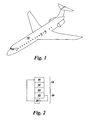
- Figure 1 is an illustration of an aircraft fuselage 10 of a passenger jet.
- Figure 2 is block diagram of an inspection system 12 for use with an aircraft fuselage, such as, aircraft fuselage 10 in Figure 1 .
- Inspection system 12 can detect defects in the aircraft fuselage, such as cracks, corrosion, delaminations, disbonds, etc. Inspection system 12 may also be used with other types of aircraft fuselages, structural components, and materials that include these types of defects. More specifically, inspection system 12 includes a moveable detector 14 coupled in synchronous motion with an energy source (not shown).
- inspection system 12 is a high-speed digital radiography system, such as the DXR-500 available from General Electric Inspection Technology, Cincinnati, Ohio. However, as will be appreciated by those in the art, other systems can be used within the scope of the present invention.
- a collision avoidance system (CAS) 20 is coupled to inspection system 12 in order to prevent contact between inspection system 12 and fuselage 10 during the inspection process.
- CAS 20 includes at least one proximity sensor 22, at least one protection device 24, and a collision monitor 26.
- Proximity sensor 22 is electrically coupled to detector 14.
- proximity sensor 22 is remotely coupled to detector 14.
- Proximity sensor 22 is a group of sensors that includes a combination of at least an infrared sensor, and an accelerometer. An infrared sensor allows for measuring distance between detector 14 and fuselage 10. An accelerometer allows for measuring detector speed.
- proximity sensor 22 In operation, proximity sensor 22 generates signals during the operation of detector 14 and transmits those signals to collision monitor 26. If during the inspection process proximity sensor 22 detects an imminent collision, then a signal is transmitted to collision monitor 26. Monitor 26 is configured to send an imminent collision signal to an inspection system stopping mechanism 28. Stopping mechanism 28 is configured to immediately halt the motion of detector 14 and facilitate preventing a collision between detector 14 and fuselage 10. In one embodiment that does not form part of the invention, stopping mechanism 28 is a manipulator that moves detector 14 away from fuselage 10.
- protection device 24 is coupled to inspection system 12.
- protection device 24 includes, but is not limited to, one or a combination of at least an air-filled bladder, a balloon, or an airbag system.
- protection device 24 includes other devices capable of protecting detector 14 as described herein.
- Protection device 24 is in electrical communication with stopping mechanism 28 such that during operation, when stopping mechanism 28 receives an imminent collision signal from monitor 26, protection device 24 is deployed. Accordingly, detector 14 does not contact fuselage 10.
- protection device 24 is in electrical communication with proximity sensor 22 such that when proximity sensor 22 detects an imminent collision, protection device 24 is deployed and prevents contact between detector 14 and fuselage 10.
- the above-described collision avoidance system 22 for an aircraft fuselage inspection system 12 is both cost-effective and highly reliable.
- the inspection system receives input from at least one proximity sensor coupled to the collision avoidance system to facilitate the prevention of contact between the movable detector and the aircraft fuselage.
- the collision avoidance system allows non-destructive inspections of aircraft fuselage frames. As a result, the inspection system can perform high-speed digital radiography on aircraft fuselages in close proximity without concern of damage to the detector or the fuselage or loss of image quality.
Description
- This invention relates generally to aircraft fuselage frames, and more particularly to methods and systems for non-destructive inspection of aircraft fuselage frames.
- In order to facilitate performing high-speed digital radiography for defect detection on passenger aircraft fuselage frames in both a timely and cost efficient manner, speed of data collection is primary. Speed can be addressed by rapid image acquisition, which can be accomplished through the synchronous motion of the energy source and the detector. In order to achieve adequate image quality, the detector must be located close to and along the outside of the aircraft fuselage to reduce the effects of magnification.
- The proximity of the inspection system to the aircraft fuselage increases the potential for collision and damage to both the aircraft and the inspection system. To facilitate preventing collision and damage, at least some method of avoidance and protection is required.
- A system and a method such as defined in the preamble of the independent claims is know from
WO-A-02/18958 - In one aspect, a method for inspecting an aircraft fuselage according to claim 1 is provided.
- In another aspect, an apparatus for inspecting an aircraft fuselage according to claim 2 is provided.
- In another aspect, an inspection system for inspecting an aircraft fuselage is provided.
-
-
Figure 1 is an illustration of an aircraft fuselage; and -
Figure 2 is a block diagram of a collision avoidance system coupled to an inspection system for use with an aircraft fuselage. -
Figure 1 is an illustration of anaircraft fuselage 10 of a passenger jet.Figure 2 is block diagram of aninspection system 12 for use with an aircraft fuselage, such as,aircraft fuselage 10 inFigure 1 .Inspection system 12 can detect defects in the aircraft fuselage, such as cracks, corrosion, delaminations, disbonds, etc.Inspection system 12 may also be used with other types of aircraft fuselages, structural components, and materials that include these types of defects. More specifically,inspection system 12 includes amoveable detector 14 coupled in synchronous motion with an energy source (not shown). In one embodiment,inspection system 12 is a high-speed digital radiography system, such as the DXR-500 available from General Electric Inspection Technology, Cincinnati, Ohio. However, as will be appreciated by those in the art, other systems can be used within the scope of the present invention. - In operation,
inspection system 12 rapidly passes close to and alongfuselage 10. A collision avoidance system (CAS) 20 is coupled toinspection system 12 in order to prevent contact betweeninspection system 12 andfuselage 10 during the inspection process.CAS 20 includes at least oneproximity sensor 22, at least oneprotection device 24, and acollision monitor 26.Proximity sensor 22 is electrically coupled todetector 14. In one embodiment,proximity sensor 22 is remotely coupled todetector 14.Proximity sensor 22 is a group of sensors that includes a combination of at least an infrared sensor, and an accelerometer. An infrared sensor allows for measuring distance betweendetector 14 andfuselage 10. An accelerometer allows for measuring detector speed. - In operation,
proximity sensor 22 generates signals during the operation ofdetector 14 and transmits those signals tocollision monitor 26. If during the inspectionprocess proximity sensor 22 detects an imminent collision, then a signal is transmitted tocollision monitor 26. Monitor 26 is configured to send an imminent collision signal to an inspection system stopping mechanism 28. Stopping mechanism 28 is configured to immediately halt the motion ofdetector 14 and facilitate preventing a collision betweendetector 14 andfuselage 10. In one embodiment that does not form part of the invention, stopping mechanism 28 is a manipulator that movesdetector 14 away fromfuselage 10. - A
protection device 24 is coupled toinspection system 12. In one embodiment,protection device 24 includes, but is not limited to, one or a combination of at least an air-filled bladder, a balloon, or an airbag system. In another embodiment,protection device 24 includes other devices capable of protectingdetector 14 as described herein. -
Protection device 24 is in electrical communication with stopping mechanism 28 such that during operation, when stopping mechanism 28 receives an imminent collision signal frommonitor 26,protection device 24 is deployed. Accordingly,detector 14 does not contactfuselage 10. In an alternative embodiment,protection device 24 is in electrical communication withproximity sensor 22 such that whenproximity sensor 22 detects an imminent collision,protection device 24 is deployed and prevents contact betweendetector 14 andfuselage 10. - The above-described
collision avoidance system 22 for an aircraftfuselage inspection system 12 is both cost-effective and highly reliable. The inspection system receives input from at least one proximity sensor coupled to the collision avoidance system to facilitate the prevention of contact between the movable detector and the aircraft fuselage. Furthermore, the collision avoidance system allows non-destructive inspections of aircraft fuselage frames. As a result, the inspection system can perform high-speed digital radiography on aircraft fuselages in close proximity without concern of damage to the detector or the fuselage or loss of image quality. - While the invention has been described in terms of various specific embodiments, those skilled in the art will recognize that the invention can be practiced with modification within the scope of the claims.
Claims (2)
- A method for inspecting an aircraft fuselage (10) using an inspection system (12) including a moveable detector (14), said method comprising:coupling a collision avoidance system (20) to the inspection system detector;monitoring the collision avoidance system during operation of the inspection system; andcontrolling operation of the inspection system with the collision avoidance system; characterized in that:said collision avoidance system (20) comprises at least one protection device (24), at least one proximity sensor (22) and a collision monitor (26), said proximity sensor (22) comprising a group of sensors that includes at least an infrared sensor and an accelerometer; andwherein said protection device (24) is in electrical communication with the proximity sensor (22) or a stopping mechanism (28) in communication which said collision monitor (26) such that when proximity sensor (22) detects an imminent collision, protection device (24) is deployed to prevent contact between the detector (14) and the fuselage (10).
- An apparatus for inspecting an aircraft fuselage (10) comprising:a moveable detector (14); anda collision avoidance system (20) in electrical communication with said moveable detector to control said moveable detector for inspecting the aircraft fuselage; characterized in that:said collision avoidance system (20) comprises at least one protection device (24), at least one proximity sensor (22) and a collision monitor (26), said proximity sensor (22) comprising a group of sensors that includes at least an infrared sensor and an accelerometer; andwherein said protection device (24) is in electrical communication with the proximity sensor (22) or a stopping mechanism (28) in communication which said collision monitor (26) such that when proximity sensor (22) detects an imminent collision, protection device (24) is deployed to prevent contact between the detector (14) and the fuselage (10).
Applications Claiming Priority (3)
| Application Number | Priority Date | Filing Date | Title |
|---|---|---|---|
| US64291 | 2002-06-28 | ||
| US10/064,291 US6662088B1 (en) | 2002-06-28 | 2002-06-28 | Methods and systems for inspecting aircraft fuselage frames |
| PCT/US2003/020953 WO2004003530A1 (en) | 2002-06-28 | 2003-06-26 | Methods and systems for inspecting aircraft fuselage frames |
Publications (2)
| Publication Number | Publication Date |
|---|---|
| EP1520167A1 EP1520167A1 (en) | 2005-04-06 |
| EP1520167B1 true EP1520167B1 (en) | 2013-09-11 |
Family
ID=29709240
Family Applications (1)
| Application Number | Title | Priority Date | Filing Date |
|---|---|---|---|
| EP03762327.9A Expired - Fee Related EP1520167B1 (en) | 2002-06-28 | 2003-06-26 | Method and system for inspecting aircraft fuselage frames |
Country Status (8)
| Country | Link |
|---|---|
| US (1) | US6662088B1 (en) |
| EP (1) | EP1520167B1 (en) |
| JP (1) | JP4520850B2 (en) |
| AU (1) | AU2003253788A1 (en) |
| BR (1) | BR0312401A (en) |
| CA (1) | CA2490059C (en) |
| SG (1) | SG173935A1 (en) |
| WO (1) | WO2004003530A1 (en) |
Families Citing this family (9)
| Publication number | Priority date | Publication date | Assignee | Title |
|---|---|---|---|---|
| US7467070B2 (en) * | 2004-10-26 | 2008-12-16 | Meyer Eric S | Methods and systems for modeling stress intensity solutions for integrally stiffened panels |
| JP4704735B2 (en) * | 2004-11-04 | 2011-06-22 | 株式会社島津製作所 | X-ray fluoroscope |
| DE102005007094B4 (en) * | 2005-02-16 | 2007-03-29 | Siemens Ag | Digital flat detector for the detection of X-rays |
| US7266174B2 (en) * | 2005-03-07 | 2007-09-04 | General Electric Company | Radiographic inspection of airframes and other large objects |
| US20080061940A1 (en) * | 2006-08-03 | 2008-03-13 | Kimberly-Clark Worldwide, Inc. | Smart antenna system for reading data tags |
| EA022348B1 (en) * | 2008-07-03 | 2015-12-30 | Юниверсити Оф Вирджиния Пэтент Фаундейшн | Unit dosage of apadenoson |
| US8886388B2 (en) * | 2009-06-29 | 2014-11-11 | The Boeing Company | Embedded damage detection system for composite materials of an aircraft |
| US8693613B2 (en) * | 2010-01-14 | 2014-04-08 | General Electric Company | Nuclear fuel pellet inspection |
| US8983172B2 (en) * | 2012-12-28 | 2015-03-17 | Modern Technology Solutions, Inc. | Visual inspection apparatus, secure one-way data transfer device and methods therefor |
Citations (2)
| Publication number | Priority date | Publication date | Assignee | Title |
|---|---|---|---|---|
| US5359542A (en) * | 1991-12-20 | 1994-10-25 | The Boeing Company | Variable parameter collision avoidance system for aircraft work platforms |
| WO2002018958A2 (en) * | 2000-08-25 | 2002-03-07 | Aerobotics, Inc. | Non-destructive inspection, testing and evaluation system for intact aircraft and components and methods therefore |
Family Cites Families (38)
| Publication number | Priority date | Publication date | Assignee | Title |
|---|---|---|---|---|
| US3940952A (en) | 1973-10-23 | 1976-03-02 | Battelle Memorial Institute | Detecting abnormality |
| US4237454A (en) | 1979-01-29 | 1980-12-02 | General Electric Company | System for monitoring bearings and other rotating equipment |
| US4213183A (en) | 1979-03-22 | 1980-07-15 | Adaptronics, Inc. | System for nondestructive evaluation of material flaw characteristics |
| JPS57151938A (en) * | 1981-03-17 | 1982-09-20 | Toshiba Corp | Contact safety device of scintillation camera |
| US4480480A (en) * | 1981-05-18 | 1984-11-06 | Scott Science & Technology, Inc. | System for assessing the integrity of structural systems |
| US4583854A (en) | 1982-07-15 | 1986-04-22 | General Electric Company | High resolution electronic automatic imaging and inspecting system |
| SU1207676A1 (en) * | 1984-06-25 | 1986-01-30 | Новомосковский Ордена Трудового Красного Знамени Трубный Завод Им.50-Летия Советской Украины | Apparatus for automatic tracing of butt joint being welded |
| US4647220A (en) * | 1984-07-09 | 1987-03-03 | Lockheed Corporation | Method of and apparatus for detecting corrosion utilizing infrared analysis |
| IL80333A (en) | 1985-12-30 | 1991-01-31 | Gen Electric | Radiation detector employing solid state scintillator material and preparation methods therefor |
| US4813062A (en) | 1986-08-13 | 1989-03-14 | Milliken Research Corporation | Radio-opaque marker and method |
| US4873708A (en) | 1987-05-11 | 1989-10-10 | General Electric Company | Digital radiographic imaging system and method therefor |
| US5112566A (en) | 1989-04-12 | 1992-05-12 | General Electric Company | Device for dimensionally characterizing elongate components |
| US4943732A (en) | 1989-08-16 | 1990-07-24 | Micrion Corporation | Method and apparatus for defect detection and location |
| US5111048A (en) | 1990-09-27 | 1992-05-05 | General Electric Company | Apparatus and method for detecting fatigue cracks using infrared thermography |
| US5097495A (en) * | 1991-03-28 | 1992-03-17 | General Electric Company | Collision detection control system |
| US5318254A (en) * | 1991-06-28 | 1994-06-07 | Conceptual Solutions, Inc. | Aircraft maintenance robot |
| US5197361A (en) | 1991-10-11 | 1993-03-30 | General Electric Company | Surface contouring tool |
| ES2130253T3 (en) | 1992-01-31 | 1999-07-01 | Northrop Grumman Corp | ARRANGED SYSTEM WITH PARASITE CURRENT PROBE. |
| US5237598A (en) * | 1992-04-24 | 1993-08-17 | Albert Richard D | Multiple image scanning X-ray method and apparatus |
| US5410406A (en) * | 1993-02-01 | 1995-04-25 | Holographics Inc. | Method and apparatus for nondestructive inspection utilizing phase integration and recording of induced vibrating nodal patterns |
| US5568532A (en) * | 1994-08-12 | 1996-10-22 | Southeastern Universities Research Association, Inc. | Examination system utilizing ionizing radiation and a flexible, miniature radiation detector probe |
| US5659248A (en) | 1994-10-17 | 1997-08-19 | General Electric Company | Multilayer eddy current probe array for complete coverage of an inspection surface without mechanical scanning |
| JPH08198198A (en) * | 1995-01-27 | 1996-08-06 | Shimadzu Corp | Airframe washing device |
| US5805664A (en) | 1995-10-02 | 1998-09-08 | General Electric Company | Imager control system with contact detector |
| US5836068A (en) * | 1997-04-14 | 1998-11-17 | Northrop Grumman Corporation | Mobile gantry tool and method |
| US5969260A (en) | 1998-03-30 | 1999-10-19 | Mcdonnell Douglas Corporation | Remotely interrogatable apparatus and method for detecting defects in structural members |
| US6252393B1 (en) | 1998-06-23 | 2001-06-26 | General Electric Company | System and method for normalizing and calibrating a sensor array |
| US6175658B1 (en) | 1998-07-10 | 2001-01-16 | General Electric Company | Spatially-selective edge enhancement for discrete pixel images |
| EP1105717A4 (en) * | 1998-08-18 | 2006-08-16 | Lockheed Corp | Digital radiographic weld inspection system |
| JP2000111530A (en) * | 1998-10-02 | 2000-04-21 | Technological Res Assoc Of Mega-Float | Method and apparatus for crack flaw detection of welded part |
| US6239438B1 (en) | 1998-11-19 | 2001-05-29 | General Electric Company | Dual acquisition imaging method and apparatus |
| US6115451A (en) | 1998-12-22 | 2000-09-05 | General Electric Company | Artifact elimination in digital radiography |
| JP4663941B2 (en) | 1999-09-16 | 2011-04-06 | ウェイン・ステイト・ユニバーシティ | Compact non-contact acoustic infrared device for remote non-destructive inspection |
| US6236049B1 (en) | 1999-09-16 | 2001-05-22 | Wayne State University | Infrared imaging of ultrasonically excited subsurface defects in materials |
| JP3274446B2 (en) * | 1999-11-29 | 2002-04-15 | 東芝アイティー・コントロールシステム株式会社 | Computer tomography apparatus and computer tomography method |
| US6466643B1 (en) * | 2000-01-07 | 2002-10-15 | General Electric Company | High speed digital radiographic inspection of aircraft fuselages |
| PL349169A1 (en) * | 2000-09-12 | 2002-03-25 | Gen Electric | Method of and apparatus for radiographically inspecting the fuselages of aircrafts |
| US6341153B1 (en) | 2000-10-27 | 2002-01-22 | Genesis Engineering Company | System and method for portable nondestructive examination with realtime three-dimensional tomography |
-
2002
- 2002-06-28 US US10/064,291 patent/US6662088B1/en not_active Expired - Lifetime
-
2003
- 2003-06-26 SG SG2010012854A patent/SG173935A1/en unknown
- 2003-06-26 WO PCT/US2003/020953 patent/WO2004003530A1/en active Search and Examination
- 2003-06-26 JP JP2004518231A patent/JP4520850B2/en not_active Expired - Fee Related
- 2003-06-26 EP EP03762327.9A patent/EP1520167B1/en not_active Expired - Fee Related
- 2003-06-26 AU AU2003253788A patent/AU2003253788A1/en not_active Abandoned
- 2003-06-26 BR BRPI0312401-0A patent/BR0312401A/en not_active Application Discontinuation
- 2003-06-26 CA CA2490059A patent/CA2490059C/en not_active Expired - Fee Related
Patent Citations (2)
| Publication number | Priority date | Publication date | Assignee | Title |
|---|---|---|---|---|
| US5359542A (en) * | 1991-12-20 | 1994-10-25 | The Boeing Company | Variable parameter collision avoidance system for aircraft work platforms |
| WO2002018958A2 (en) * | 2000-08-25 | 2002-03-07 | Aerobotics, Inc. | Non-destructive inspection, testing and evaluation system for intact aircraft and components and methods therefore |
Also Published As
| Publication number | Publication date |
|---|---|
| AU2003253788A1 (en) | 2004-01-19 |
| US6662088B1 (en) | 2003-12-09 |
| WO2004003530A1 (en) | 2004-01-08 |
| CA2490059A1 (en) | 2004-01-08 |
| EP1520167A1 (en) | 2005-04-06 |
| JP2005531773A (en) | 2005-10-20 |
| BR0312401A (en) | 2007-06-19 |
| US20040002797A1 (en) | 2004-01-01 |
| CA2490059C (en) | 2010-12-07 |
| SG173935A1 (en) | 2011-09-29 |
| JP4520850B2 (en) | 2010-08-11 |
Similar Documents
| Publication | Publication Date | Title |
|---|---|---|
| EP1520167B1 (en) | Method and system for inspecting aircraft fuselage frames | |
| JP2006250932A (en) | Radiographic inspection for airframe and other big object | |
| CN110525452A (en) | A kind of anti-pinch detection system and method between subway shield door and train | |
| CN105445809A (en) | Apparatus and method for inspecting mobile target | |
| CN105484604B (en) | Hangar front door control system and method | |
| CN206096502U (en) | Train shield door foreign matter detecting system | |
| CN107497856A (en) | The method and apparatus of pipe continuous rolling | |
| EP2476499A2 (en) | Nuclear power plant construction preparation unit with detection and marking devices ; nuclear power plant construction system with such preparation unit ; nuclear power plant construction method with detection and marking steps | |
| CA2313910C (en) | Method and apparatus for detecting leakage current on a two wire dc or ac power line | |
| JP5173371B2 (en) | Vehicle home detection device | |
| JP2007246213A (en) | Vibration suppression device for elevator | |
| CN107685230A (en) | It is a kind of to be used to dismantle the internal device and method for dismounting for having press device | |
| JP3652814B2 (en) | Safety equipment for automatic painting equipment | |
| WO2022138479A1 (en) | Monitoring system and monitoring method | |
| JP2004334977A (en) | Master disk exposure apparatus and optical system collision avoidance exposure method | |
| CN114011733A (en) | Glass disc protection system and glass disc protection method | |
| JP2001165867A (en) | Surface inspection device | |
| CN115289960A (en) | Steel coil end face quality detection system and method | |
| JPH06331609A (en) | Ultrasonic flaw detecting device | |
| CN117388178A (en) | Control circuit and control method based on terahertz cigarette bead explosion nondestructive testing equipment | |
| Loupos et al. | Integrated ROBOTIC solution for tunnel structural evaluation and characterization—ROBO-SPECT EC project | |
| KR20070094141A (en) | Tripod trouble sensing and handling method of korean-type high-speed railway | |
| JP2010263756A (en) | Train crew support system and method of controlling train traveling | |
| JPS5977351A (en) | Ultrasonic flaw detector | |
| CN112248987A (en) | Intelligent stopping system and method for special equipment |
Legal Events
| Date | Code | Title | Description |
|---|---|---|---|
| PUAI | Public reference made under article 153(3) epc to a published international application that has entered the european phase |
Free format text: ORIGINAL CODE: 0009012 |
|
| 17P | Request for examination filed |
Effective date: 20050128 |
|
| AK | Designated contracting states |
Kind code of ref document: A1 Designated state(s): AT BE BG CH CY CZ DE DK EE ES FI FR GB GR HU IE IT LI LU MC NL PT RO SE SI SK TR |
|
| AX | Request for extension of the european patent |
Extension state: AL LT LV MK |
|
| DAX | Request for extension of the european patent (deleted) | ||
| RBV | Designated contracting states (corrected) |
Designated state(s): DE FR GB |
|
| 17Q | First examination report despatched |
Effective date: 20061124 |
|
| RIN1 | Information on inventor provided before grant (corrected) |
Inventor name: HERD, KENNETH, GORDON Inventor name: DIXON, ELIZABETH, LOCKENBERG Inventor name: BUENO, CLIFFORD Inventor name: HOPPLE, MICHAEL, ROBERT Inventor name: MOHR, GREGORY, ALAN |
|
| REG | Reference to a national code |
Ref country code: DE Ref legal event code: R079 Ref document number: 60344907 Country of ref document: DE Free format text: PREVIOUS MAIN CLASS: G01N0023040000 Ipc: G01N0023000000 |
|
| GRAP | Despatch of communication of intention to grant a patent |
Free format text: ORIGINAL CODE: EPIDOSNIGR1 |
|
| RIC1 | Information provided on ipc code assigned before grant |
Ipc: G01N 23/00 20060101AFI20130315BHEP |
|
| INTG | Intention to grant announced |
Effective date: 20130412 |
|
| GRAS | Grant fee paid |
Free format text: ORIGINAL CODE: EPIDOSNIGR3 |
|
| GRAA | (expected) grant |
Free format text: ORIGINAL CODE: 0009210 |
|
| AK | Designated contracting states |
Kind code of ref document: B1 Designated state(s): DE FR GB |
|
| REG | Reference to a national code |
Ref country code: GB Ref legal event code: FG4D |
|
| REG | Reference to a national code |
Ref country code: DE Ref legal event code: R096 Ref document number: 60344907 Country of ref document: DE Effective date: 20131107 |
|
| REG | Reference to a national code |
Ref country code: DE Ref legal event code: R097 Ref document number: 60344907 Country of ref document: DE |
|
| PLBE | No opposition filed within time limit |
Free format text: ORIGINAL CODE: 0009261 |
|
| STAA | Information on the status of an ep patent application or granted ep patent |
Free format text: STATUS: NO OPPOSITION FILED WITHIN TIME LIMIT |
|
| 26N | No opposition filed |
Effective date: 20140612 |
|
| REG | Reference to a national code |
Ref country code: DE Ref legal event code: R097 Ref document number: 60344907 Country of ref document: DE Effective date: 20140612 |
|
| REG | Reference to a national code |
Ref country code: FR Ref legal event code: PLFP Year of fee payment: 13 |
|
| PGFP | Annual fee paid to national office [announced via postgrant information from national office to epo] |
Ref country code: GB Payment date: 20150629 Year of fee payment: 13 Ref country code: DE Payment date: 20150629 Year of fee payment: 13 |
|
| PGFP | Annual fee paid to national office [announced via postgrant information from national office to epo] |
Ref country code: FR Payment date: 20150617 Year of fee payment: 13 |
|
| REG | Reference to a national code |
Ref country code: DE Ref legal event code: R119 Ref document number: 60344907 Country of ref document: DE |
|
| GBPC | Gb: european patent ceased through non-payment of renewal fee |
Effective date: 20160626 |
|
| REG | Reference to a national code |
Ref country code: FR Ref legal event code: ST Effective date: 20170228 |
|
| PG25 | Lapsed in a contracting state [announced via postgrant information from national office to epo] |
Ref country code: FR Free format text: LAPSE BECAUSE OF NON-PAYMENT OF DUE FEES Effective date: 20160630 Ref country code: DE Free format text: LAPSE BECAUSE OF NON-PAYMENT OF DUE FEES Effective date: 20170103 |
|
| PG25 | Lapsed in a contracting state [announced via postgrant information from national office to epo] |
Ref country code: GB Free format text: LAPSE BECAUSE OF NON-PAYMENT OF DUE FEES Effective date: 20160626 |