EP1520518A2 - Biopsy instrument with internal specimen collection mechanism - Google Patents
Biopsy instrument with internal specimen collection mechanism Download PDFInfo
- Publication number
- EP1520518A2 EP1520518A2 EP04256067A EP04256067A EP1520518A2 EP 1520518 A2 EP1520518 A2 EP 1520518A2 EP 04256067 A EP04256067 A EP 04256067A EP 04256067 A EP04256067 A EP 04256067A EP 1520518 A2 EP1520518 A2 EP 1520518A2
- Authority
- EP
- European Patent Office
- Prior art keywords
- cutter
- needle
- specimen
- tissue
- biopsy
- Prior art date
- Legal status (The legal status is an assumption and is not a legal conclusion. Google has not performed a legal analysis and makes no representation as to the accuracy of the status listed.)
- Granted
Links
Images


Classifications
-
- A—HUMAN NECESSITIES
- A61—MEDICAL OR VETERINARY SCIENCE; HYGIENE
- A61B—DIAGNOSIS; SURGERY; IDENTIFICATION
- A61B10/00—Other methods or instruments for diagnosis, e.g. instruments for taking a cell sample, for biopsy, for vaccination diagnosis; Sex determination; Ovulation-period determination; Throat striking implements
- A61B10/02—Instruments for taking cell samples or for biopsy
- A61B10/0233—Pointed or sharp biopsy instruments
- A61B10/0266—Pointed or sharp biopsy instruments means for severing sample
- A61B10/0275—Pointed or sharp biopsy instruments means for severing sample with sample notch, e.g. on the side of inner stylet
-
- A—HUMAN NECESSITIES
- A61—MEDICAL OR VETERINARY SCIENCE; HYGIENE
- A61B—DIAGNOSIS; SURGERY; IDENTIFICATION
- A61B10/00—Other methods or instruments for diagnosis, e.g. instruments for taking a cell sample, for biopsy, for vaccination diagnosis; Sex determination; Ovulation-period determination; Throat striking implements
- A61B10/02—Instruments for taking cell samples or for biopsy
- A61B10/0233—Pointed or sharp biopsy instruments
- A61B10/0283—Pointed or sharp biopsy instruments with vacuum aspiration, e.g. caused by retractable plunger or by connected syringe
-
- A—HUMAN NECESSITIES
- A61—MEDICAL OR VETERINARY SCIENCE; HYGIENE
- A61B—DIAGNOSIS; SURGERY; IDENTIFICATION
- A61B10/00—Other methods or instruments for diagnosis, e.g. instruments for taking a cell sample, for biopsy, for vaccination diagnosis; Sex determination; Ovulation-period determination; Throat striking implements
- A61B10/02—Instruments for taking cell samples or for biopsy
- A61B2010/0208—Biopsy devices with actuators, e.g. with triggered spring mechanisms
-
- A—HUMAN NECESSITIES
- A61—MEDICAL OR VETERINARY SCIENCE; HYGIENE
- A61B—DIAGNOSIS; SURGERY; IDENTIFICATION
- A61B10/00—Other methods or instruments for diagnosis, e.g. instruments for taking a cell sample, for biopsy, for vaccination diagnosis; Sex determination; Ovulation-period determination; Throat striking implements
- A61B10/02—Instruments for taking cell samples or for biopsy
- A61B2010/0225—Instruments for taking cell samples or for biopsy for taking multiple samples
Definitions
- a number of biopsy devices have been designed and commercialized for use in combination with imaging devices.
- One such biopsy instrument is the BIOPTY® gun, available from C.R. Bard, Inc. and described in U.S. Pat. Nos. 4,699,154 and 4,944,308 as well as in U.S. Reissued Pat No. Re. 34,056.
- the BIOPTY® gun is a core sampling biopsy device in which the biopsy needle is spring-powered.
- the TRUE CUT® needle manufactured by Travenol Laboratories. This TRUE CUT® needle collects a single core of tissue using a pointed element with a side-facing notch to receive tissue and an outer, sharpened sliding cannula to cut the core sample from the surrounding tissue.
- the present invention is a handheld biopsy device that may be used in combination with another handheld imaging device such as an ultrasound imaging device.
- the present invention provides a biopsy instrument for the collection of at least one soft tissue sample from a surgical patient.
- the present invention provides a biopsy instrument having a handpiece that is independently manipulatable by hand movement of the instrument toward and away from the patient.
- the present invention incorporates an elongated needle extending from the distal end of the hand piece and having a needle lumen therein and a sharpened distal end for entering tissue when the hand piece is moved by hand toward the surgical patient so as to cause the sharpened distal end to penetrate tissue.
- the present invention includes a cutter rotational transmission contained within the hand piece and operationally connected to the elongated cutter.
- a cutter rotational transmission When the cutter rotational transmission is actuated, die cutter is rotated about its longitudinal axis.
- end stop 40B on elongated rod 40 has been advanced by the boss 44 of drive block 38B.
- end stop 40A contacts boss 42 of drive block 38A, see figures 8 and 9, thereby drawing drive block 38A onto worm gear 22.
- coil spring 46 is once again placed into a compression mode thereby continuing to bias drive block 38A and 38B apart.
- specimen push rod 18 also advances, within lower lumen 19.
- biopsy needle 115 is inserted into the tissue to be sampled as illustrated in figure 24.
- a vacuum supplied from vacuum tube 129 through port 128, is provided inside needle 115.
- Tissue 150 is drawn into specimen port 117 by action of the applied vacuum through orifices 119 in needle 115.
- Drive shaft 131 is rotated thereby rotating cutter 120 through the engagement of cutter drive gear 124 and drive gear 114.
- Simultaneously drive shaft 130 is rotated , rotating worm gear 122, whereby drive block 138B advances toward the distal end of the biopsy instrument 100.
- rotating cutter 120 also advances until drive block 138B runs off worm gear 122 and onto the non-threaded portion 132B of drive shaft 130.
- cutter 120 will have cut and encapsulated a sample portion of tissue 151 as shown in figure 27.
Abstract
Description
- The present invention generally relates to instruments for surgically sampling living tissue. More particularly the present invention relates to an improved biopsy probe for acquiring subcutaneous biopsies and/or removing lesions etc.
- The diagnosis and treatment of patients with cancerous tumors, pre-malignant conditions, and other disorders has long been an area of intense investigation. Non-invasive methods for examining tissue include palpation, X-ray, MRI, CT, and ultrasound imaging. When the physician suspects that a tissue may contain cancerous cells, a biopsy may be done using either an open procedure or a percutaneous procedure. For an open procedure, a scalpel is used by the surgeon to create a large incision in the tissue in order to provide direct viewing and access to the tissue mass of interest. The entire mass (excisional biopsy) or a part of the mass (incisional biopsy) may then be removed. For a percutaneous biopsy, a needle-like instrument is used through a very small incision to access the tissue mass of interest and to obtain a tissue sample for later examination and analysis. The advantages of the percutaneous method as compared to the open method may be significant and may include: less recovery time for the patient, less pain, less surgical time, lower cost, and less disfigurement of the patient's anatomy. Use of the percutaneous method in combination with imaging devices such as X-ray and ultrasound has resulted in highly reliable diagnoses and treatments.
- Generally there are two ways to obtain percutaneously a portion of tissue from within the body, by aspiration or by core sampling. Aspiration of the tissue through a fine needle requires the tissue to be fragmented into pieces small enough to be withdrawn in a fluid medium. The method is less intrusive than other known sampling techniques, but one can only examine cells in the liquid (cytology) and not the cells and the structure (pathology). In core biopsy, a core or fragment of tissue is obtained for histologic examination, which may be done via a frozen or paraffin section.
- The type of biopsy used depends mainly on various factors present in the patient, and no single procedure is ideal for all cases. Core biopsy, however, is very useful in a number of conditions and is widely used by physicians.
- A number of biopsy devices have been designed and commercialized for use in combination with imaging devices. One such biopsy instrument is the BIOPTY® gun, available from C.R. Bard, Inc. and described in U.S. Pat. Nos. 4,699,154 and 4,944,308 as well as in U.S. Reissued Pat No. Re. 34,056. The BIOPTY® gun is a core sampling biopsy device in which the biopsy needle is spring-powered. However, when using the BIOPTY® gun, the breast or organ must be punctured and the device is re-inserted each time a sample is taken. Another core biopsy device is the TRUE CUT® needle manufactured by Travenol Laboratories. This TRUE CUT® needle collects a single core of tissue using a pointed element with a side-facing notch to receive tissue and an outer, sharpened sliding cannula to cut the core sample from the surrounding tissue.
- Aspiration biopsy devices for obtaining biopsy samples from the body are described in the following: U.S. Pat. No. 5,492,130; U.S. Pat. No. 5,526,821; U.S. Pat. No. 5,429,138; and U.S. Pat. No. 5,027,827. These patents describe devices, which use the aspiration method of liquid suspended tissue extraction rather than core sampling to extract tissue.
- To overcome operator error associated with such devices, and to enable multiple sampling of the tissue without having to reenter the tissue for each sample, a biopsy instrument now marketed under the trade name MAMMOTOME™ was developed by Ethicon Endo-Surgery, Inc. The following patent documents disclose various biopsy devices and are incorporated herein by reference in their entirety: U.S. Pat. Nos. 6,273,862; 6,231,522; 6,228,055; 6,120,462; 6,086,544; 6,077,230; 6,017,316; 6,007,497; 5,980,469; 5,964,716; 5,928,164; 5,775,333; 5,769,086; 5,649,547 and 5,526,822. The MAMMOTOME™ instrument is a type of image-guided, percutaneous, coring, breast biopsy instrument. It is vacuum-assisted and some of the steps for retrieving the tissue samples have been automated. The physician uses this device to capture "actively" (using the vacuum) the tissue prior to severing it from the body. This allows for sampling tissues of varying hardness. In the MAMMOTOME™ biopsy instrument, the cutter is rotated using a motor drive mounted in the instrument while the surgeon manually moves the cutter back and forth by a knob on the outside of the instrument. Thus, the surgeon is able, through tactile feedback, to determine whether the blade is effectively cutting tissue or if there is a problem, such as binding or stalling. The surgeon may then adjust the speed at which the blade is moved through the tissue, stop the blade, or back the blade away from the tissue. The device can also be used to collect multiple samples in numerous positions about its longitudinal axis, without removing the biopsy needle from the body. These features allow for substantial sampling of large lesions and complete removal of small ones. In the MAMMOTOME™, a vacuum chamber is attached alongside and fluidly connected to an elongated, hollow needle. The vacuum supplied through the vacuum chamber pulls tissue into the lateral receiving port of the hollow needle.
- For breast biopsies, the devices described so far are most commonly used in combination with either X-ray or ultrasound imaging to locate suspicious tissue, although other imaging modalities such as magnetic resonance imaging are also available. When using, for example, the MAMMOTOME™ biopsy device with an X-ray stereotactic table, the biopsy device is attached to a movable, mechanical mounting arm. The patient lies face down on the table and the patient's breast is guided through an opening in the stereotactic table. Several X-ray images of the breast are taken from different angles to determine the location of the calcifications or lesions, which are to be removed from the breast. Next the mounting arm is manually repositioned so that the biopsy device is properly aligned with the breast. Then the mounting arm is manipulated to push the needle of the biopsy device into the breast until the tip of the needle is positioned alongside the tissue to be sampled. Additional X-ray images are then made to confirm that the port on the distal end of the needle is in the proper position to collect the desired tissue portions. The biopsy device is then used to retrieve one or more core samples of tissue. Additional X-ray images are taken to confirm the removal of the suspect tissue. Sometimes the biopsy device and mounting arm must be repositioned during the procedure so that the tip of the piercing element is in a new location in order to retrieve more tissue samples. As this brief description illustrates, there are many time consuming steps in getting the biopsy device properly positioned to retrieve the desired tissue. In addition, the accessibility of certain parts of the breast may be hindered by the degrees of freedom of the movement of the mounting arm. Also, the size of the stereotactic table and associated equipment precludes portability of the system. It is not possible, for example, to have a number of patients being prepared for the procedure in separate rooms of a clinic, if there is only one room set-up for doing the procedure. Having a portable system would allow the surgeon to go from room-to-room and perform the procedure, and thus allow more patients to be treated in a given time period at the clinic.
- Biopsy devices are also used with other kinds of X-ray imaging systems such as those for which the patient is upright rather than lying down. The numerous steps described above for locating, confirming, and reconfirming using X-ray stereo "snapshots" are also necessary for the upright versions.
- The MAMMOTOME™ biopsy instrument may also be used with real time handheld imaging devices such as ultrasound imaging devices. When using a biopsy instrument such as the MAMMOTOME™ with a handheld ultrasound imaging device, the surgeon gains the advantage of having real time imaging of the tissue of interest. Typically the ultrasound imaging device is held in one hand and pointed at the tissue being penetrated by the needle. In order to facilitate positioning and manipulation of both the biopsy instrument and the imaging device, it is normally necessary to attach the biopsy instrument to a mechanical, articulating arm which is designed to support the weight of the biopsy instrument. In addition, since axial movement of the cutter on the MAMMOTOME™ is actuated by hand, the biopsy device must be rigidly supported to allow the surgeon to actuate the cutter without moving the tip. Alternatively, an assistant may be used to help operate the controls for the biopsy device. It would, therefore, be advantageous to design a handheld core sampling biopsy instrument wherein the cutter of the instrument was moved using a motor drive which could be actuated by the touch of a switch. Further, since some of the electrical and vacuum controls are not on the MAMMOTOME™ biopsy instrument itself, the biopsy instrument must be rigidly supported or the surgeon must have an assistant to actuate the controls. It would, therefore, be further advantageous if the electrical and vacuum controls for the biopsy device were positioned in relatively close proximity either on the instrument or, for example, on an associated generator. Automating axial movement of the cutter will, to some extent, eliminate the tactile feedback that the surgeon gets from moving the cutter blade manually. It would, therefore, be advantageous to provide a method of automatically measuring and controlling the axial movement of the cutter, which could be utilized to, for example, prevent the cutter from advancing when the port is blocked.
- In recent years several patents have issued describing handheld, motorized devices for the extraction of tissue from the body. Many of these devices are for arthroscopic surgery and are not intended for retrieving biopsy core samples of tissue for pathological analysis. The motors are for rotationally driving the cutting/milling end effectors, but not for advancing the end effectors into the tissue. Examples of arthroscopic, handheld, motorized devices include the following U.S. Pat. Nos. 4,995,877; 4,705,038; 5,192,292; 5,112,299; 5,437,630; 5,690,660; and 5,320,635.
- In U.S. Pat. No. 4,940,061 issued to Terwilliger, et al, on Jul. 10,1990, a core sampling, handheld biopsy device incorporating a battery powered motor for driving a means to penetrate and sever tissue is described. The motor axially drives a cutter to advance the cutter into tissue, thus eliminating the noise and jerking associated with mechanical stops of the spring-actuated devices. This significantly adds to the comfort of both the patient and the surgeon. However, the device does not incorporate a vacuum source for obtaining the tissue portion. As described in Burbank, et al., '822 and '333, the vacuum greatly facilitates the capturing of a complete tissue portion within the distal end port on the piercing element. Capturing more tissue with each sample reduces the number of samples required, and increases the likelihood of obtaining the diseased tissue. The Terwilliger device in '061 also does not address how to minimize leakage and spilling of the high volume of fluids present in biopsy procedures.
- The surgeon may prefer to use an X-ray imaging system for some patients, and an ultrasound imager for others. In such situations, it would be desirable to use a biopsy instrument that is adaptable to both kinds of imaging systems.
- Such an instrument could be used as a handheld instrument or also as an instrument mounted onto the ann of an X-ray stereotactic table, depending on the situation.
- It is therefore desirable to provide a more versatile and "patient friendly" biopsy device than what is currently available. The device should be particularly adapted for use without mounting to an X-ray stereotactic table. It should be a lightweight, maneuverable, handheld device, so that the surgeon may have the option to perform the biopsy procedure in combination with an ultrasound imaging device. It is desirable that the device be easily transported from room-to-room so that several patients may be prepared for the surgical procedure concurrently, thus allowing more patients to be treated in a given time period, and potentially reducing the overall cost of the surgical procedure. In addition, it is desirable to perform a biopsy with fewer steps in order to decrease the overall time of the procedure. This would be achievable by eliminating the need to set-up and operate the X-ray stereotactic table. The combination of these factors could allow the surgical procedure to be more widely available to patients than it is currently.
- It is also desirable to provide a handheld biopsy device that may be held parallel to the chest wall of the patient, so that suspect tissue masses close to the chest wall can be easily sampled. It is desirable that the surgeon be able to easily steer the penetrating tip of the handheld device towards the desired tissue to be sampled. It is further desired that the surgeon have tactile feedback as the tissue is probed by the penetrating tip of the device, to provide the surgeon with clues regarding the disease state of the tissue encountered. It is also desirable that the biopsy device be "patient friendly" by not having noisy or jerky mechanical actuations during the procedure, and by not having to be used with large machines such as an X-ray stereotactic table.
- The present invention overcomes problems associated with using a biopsy instrument that may be used only when mounted to an X-ray stereotactic system.
- In the preferred embodiment, the present invention is a handheld biopsy device that may be used in combination with another handheld imaging device such as an ultrasound imaging device. The present invention provides a biopsy instrument for the collection of at least one soft tissue sample from a surgical patient. The present invention provides a biopsy instrument having a handpiece that is independently manipulatable by hand movement of the instrument toward and away from the patient. The present invention incorporates an elongated needle extending from the distal end of the hand piece and having a needle lumen therein and a sharpened distal end for entering tissue when the hand piece is moved by hand toward the surgical patient so as to cause the sharpened distal end to penetrate tissue.
- The present invention also includes an elongated cutter with a central lumen therethrough. The cutter is disposed coaxially and slidably relative to the needle. The cutter has a cutting blade on the distal end for cutting the portion of tissue protruding into the specimen receiving port of the needle when the cutter slides distally past the port. A portion of the cut tissue is then deposited within the cutter lumen proximal to the cutting blade.
- The present invention includes a cutter rotational transmission contained within the hand piece and operationally connected to the elongated cutter. When the cutter rotational transmission is actuated, die cutter is rotated about its longitudinal axis.
- The present invention further includes a cutter axial transmission contained within the hand piece and operationally connected to the elongated cutter. When the cutter axial transmission is actuated, the cutter is slid in an axial direction relative to the needle. It is slid in the distal axial direction to cut a portion of tissue protruding into the port. It is slid in the proximal axial direction to retrieve the cut portion of tissue from the biopsy instrument.
- The biopsy device also has a power transmission source that is operationally engageable with the cutter rotational transmission for rotation of the cutter. In the preferred embodiment, the power transmission source is also operationally engageable with the cutter axial transmission for the longitudinal movement of the cutter. A first electric motor is operationally engaged to the cutter rotational transmission by a first flexible, rotatable shaft. A second electric motor is operationally engaged to the cutter axial transmission by a second flexible, rotatable shaft. The hand piece also includes a holster. The distal ends of the first and second rotatable shafts are rotatably mounted in the holster so that the first and second shafts are operationally engaged, respectively, to the cutter rotational transmission and the cutter axial transmission inside the hand piece.
- In the preferred embodiment of the present invention, a specimen collection tube is disposed in the cutter lumen of the cutter. By activating the axial transmission source, the cutter is slid fully distal to cut a portion of tissue protruding in the port. Continued activation of the axial transmission source advances the specimen push rod distally forcing it around a 180 degree bend in the tip of the needle and back into the distal end of the cutter. This action results in the specimen push rod pushing tissue specimens proximally within the cutter thereby creating space within the cutter for the next specimen. By reversing the axial transmission source, the specimen push rod retracts distally out of the tube followed by the cutter retracting proximally exposing the port for the next tissue sample. The proximal end of the tissue remover is connected to a first vacuum tube that is connected by a first connector to a fluid collection system. The fluidic contents of the cutter lumen are transported to the fluid collection system when the vacuum is actuated. A strainer on the distal end of the remover is provided to block the tissue portion from entering the remover.
- Also in the preferred embodiment, the proximal end of the needle lumen is connected by a second vacuum tube that is connected by a second connector to the fluid collection system. The fluidic contents of the needle lumen also are transported to the fluid collection system when the vacuum of the system is actuated.
- The novel features of the invention are set forth with particularity in the appended claims. The invention itself, however, both as to organization and methods of operation, together with further objects and advantages thereof, may best be understood by reference to the following description, taken in conjunction with the accompanying drawings in which:
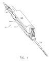
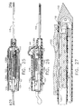
- Figure 1 presents a perspective view of a biopsy device embodying the present invention.
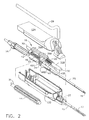
- Figure 2 presents an exploded perspective of the biopsy device illustrated in figure 1.
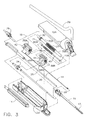
- Figure 3 presents an exploded perspective, similar to that of figure 2, wherein the component parts of the specimen push rod mechanism is further illustrated as an additional exploded pictorial.
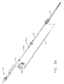
- Figure 3A presents a pictorial view of the specimen collection tube and cutter subassembly along with the specimen push rod.
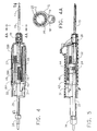
- Figure 4 presents a top view of the biopsy device illustrated in figure 1, having the top cover removed, showing the internal mechanism in its initial starting configuration.
- Figure 4A presents a cross-section taken along
line 4A-4A in figure 4. - Figure 5 presents a cross-sectional view taken along line 5-5 in figure 4.
- Figure 6 presents a bottom view of the biopsy device illustrated in figure 1, having its bottom cover removed, showing the internal mechanism in its initial starting configuration.
- Figure 7 presents a cross-sectional view of the distal end of the insertion needle illustrating tissue within the specimen sampling recess prior to being sampled.
- Figure 8 presents a top view of the biopsy device, similar to figure 4, showing the internal mechanism with the cutter at the distal end of the insertion needle.
- Figure 9 presents a cross-sectional view taken along line 9-9 in figure 8.
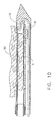
- Figure 10 presents a cross-sectional view, similar to figure 7, of the distal end of the insertion needle illustrating a tissue sample within the specimen sampling recess after having been cut.
- Figure 11 presents a top view of the biopsy device, similar to figures 4 and 8, showing the internal mechanism of the biopsy instrument with the cutter and the push rod at their extended distal configuration.
- Figure 12 presents a cross-sectional view, of the biopsy instrument, similar to figure 9, showing the internal mechanism of the biopsy instrument with the cutter and the push rod at their extended distal configuration.
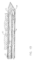
- Figure 13 presents a cross-sectional view, similar to figures 7 and 10, showing the cut tissue sample having been pushed into the sampling tube by the flexible push rod.
- Figure 14 presents a cross-sectional view, similar to figures 7 and 10, showing the cut tissue sample.
- Figure 15 presents an enlarged view of the area circled in figure 13.
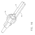
- Figure 16 presents a pictorial view of the vacuum port connector with integral knockout pin.
- Figure 17 presents a pictorial illustration of a specimen board receiving a series of collected specimens discharged, from the sampling tube, in the order that they were taken.
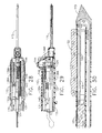
- Figure 18 a perspective view of an alternate embodiment of a biopsy device embodying the present invention.
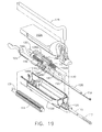
- Figure 19 presents an exploded perspective of the biopsy device illustrated in figure 18.
- Figure 20 presents an exploded perspective, similar to that of figure 19, wherein the component parts of the specimen push rod mechanism is further illustrated as an additional exploded pictorial.
- Figure 21 presents a top view of the biopsy device illustrated in figure 18, having the top cover removed, showing the internal mechanism in its initial starting configuration.
- Figure 21 A presents a cross-section taken along
line 21A-21A in figure 21. - Figure 22 presents a cross-sectional view taken along line 22-22 in figure 21.
- Figure 23 presents a bottom view of the biopsy device illustrated in figure 18, having its bottom cover removed, showing the internal mechanism in its initial starting configuration.
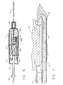
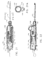
- Figure 24 presents a cross-sectional view of the distal end of the insertion needle illustrating tissue within the specimen sampling recess prior to being sampled.
- Figure 25 presents a top view of the biopsy device, similar to figure 21, showing the internal mechanism with the cutter at the distal end of the insertion needle.
- Figure 26 presents a cross-sectional view taken along line 26-26 in figure 25.
- Figure 27 presents a cross-sectional view, similar to figure 24, of the distal end of the insertion needle illustrating a tissue sample within the cutter after having been cut.
- Figure 28 presents a top view of the biopsy device, similar to figures 21 and 25, showing the internal mechanism of the biopsy instrument with the cutter and the push rod at their extended distal configuration.
- Figure 29 presents a cross-sectional view, of the biopsy instrument, similar to figure 26, showing the internal mechanism of the biopsy instrument with the cutter and the push rod at their extended distal configuration.
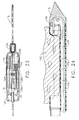
- Figure 30 presents a cross-sectional view, similar to figures 24 and 27, showing the cut tissue sample having been pushed into the cutter by the flexible push rod.
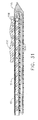
- Figure 31 presents a cross-sectional view, similar to figures 24, 27 and 28, showing multiple cut tissue samples having been sequentially pushed into the cutter by the flexible push rod.
- Referring to figures 1 through 3A, a hand held
biopsy instrument 10, embodying the present invention, is illustrated.Biopsy instrument 10 comprises anouter housing 12 comprising a top andbottom shell bottom shell 12B isbiopsy needle 15 the function of which will become apparent below. Contained withinhousing 12 isdrive mechanism 16 for operating thespecimen cutter 20 andspecimen collector tube 25 subassembly, along withspecimen push rod 18 as illustrated in figure 3A. -
Specimen collection tube 25 is coaxially positioned withincutter 20 that in turn is coaxially positioned within theupper lumen 13 of thebiopsy needle 15 as illustrated in figures 3, 3A, and 4A. Pushrod 18 is positioned within thelower lumen 19 withinbiopsy needle 15 as indicated in figures 3, 3A, and 4A. A vacuum port connector withknockout pin 26, fluidly attached to a vacuum source (not shown), is attached to the proximal end ofspecimen collection tube 25, the operation and function of which will be further explained below. Avacuum port 28, receiving thereinvacuum source tube 29, is provided at the proximal end ofneedle 15 for providing a vacuum within thelower lumen 19 ofbiopsy needle 15. The purpose of providing a vacuum withinneedle 15 will be further explained below. - Also contained within
housing 12 is elongateddrive gear 14 engagingcutter drive gear 24, as shown in figure 6, for rotatingcutter 20. Operation ofdrive mechanism 16 is provided by separately poweredworm gear 22. - As best illustrated in figure 3, the worm gear threaded
portion 22 ofdrive shaft 30 only extends over approximately the middle third ofdrive shaft 30; non threadedportions drive shaft 30 respectively, the function of which is further explained below. Positioned upondrive shaft 30 are proximal and distal drive blocks 38A and 38B.Elongated rod 40 slidingly extends throughboss 44 ondrive block 38B andboss 42 ofdrive block 38A. End stops 40A and 40B is provided at the distal ends ofrod 40, the function of which will be further described below. Acompression spring 46 is axially positioned uponrod 40 betweenboss drive blocks - When assembled in the biopsy instrument's starting or initial configuration, as illustrated in figure 2, the
cutter drive mechanism 16 comprises drive blocks 38A and 38B positioned uponworm gear 22 withblock 38A at the far proximal end and block 38B adjacent thereto. In this configuration, block 38A rests upon thenon-threaded portion 32A ofdrive shaft 30 and block 38B is threadingly engaged withworm gear 22.Compression spring 46 is fully compressed betweenbosses drive blocks drive block 38B is threadingly engaged withworm gear 22 and cannot move and block 38A is being forced againstcollar 21 at the proximal end ofdrive shaft 30 the two drive blocks cannot separate. - Coaxially positioned within
cutter 20 iscollection tube 25, as indicated in figures 3 and 4A.Collection tube 25 has anengagement feature 25A that spans over alip feature 20A on the proxial end ofcutter 20. Theengagement feature 25A enables thecollection tube 25 to advance and retract in unison with thecutter 20, but as the cutter rotates it allows thecollection tube 25 to not rotate. The subassembly comprising the cutter and collection tube is supported byjournals block 38B, such thatcutter drive gear 24 lies therebetween, as illustrated in figure 2. Thus axial movement ofdrive block 38B uponworm gear 22 also causes axial movement of the subassembly comprising the cutter and the collection tube.Cutter drive gear 24 remains engaged withelongated drive gear 14 ascutter drive gear 24 advances axially toward the distal end. The cutter and collection tube ,as a subassembly, is coaxially positioned withinneedle 15 along with and parallel to thespecimen push rod 18 as indicated in figures 3 and 4A.Specimen push rod 18 is affixed, at its proximal end, to driveblock 38A as illustrated in figure 3. Thus asdrive block 38A axially advancespush rod 18 also advances. Attached to the proximal end ofcollection tube 25 is vacuum port connector withknockout pin 26. - Figures 4, 5, and 6 illustrate the positioning of elements prior to taking a tissue sample. Drive blocks 38A and 38B are positioned at their far most proximal location as best illustrated in figures 4 and 5. In this position the cutter/specimen collection tube subassembly along with the specimen push rod are also positioned at their far most proximal location.
- To take a tissue specimen,
needle 15 is inserted into the tissue to be sampled as illustrated in figure 7. A vacuum, supplied fromvacuum 29 throughport 28 is provided insideneedle 15.Tissue 50 is drawn into specimen port by action of the applied vacuum throughorifices 19 inspecimen needle 15. Driveshaft 31 is rotated thereby rotatingcutter 20 through the engagement of cutter drive gear and drivegear 14. Simultaneously driveshaft 30 is rotated ,rotating worm gear 22, wherebydrive block 38B advances toward the distal end of thebiopsy instrument 10. Asdrive gear 38B advancesrotating cutter 20 also advances untildrive block 38B runs offworm gear 22 and onto thenon-threaded portion 32B ofdrive shaft 30. Whendrive block 38B reaches its distal end, as illustrated in figure 8,cutter 20 will have cut and encapsulated a sample portion oftissue 51 as shown in figure 10. - As
drive block 38B advances onto thenon-threaded portion 32B, ofdrive shaft 30, end stop 40B onelongated rod 40 has been advanced by theboss 44 ofdrive block 38B. Aselongated rod 40 is advanced, end stop40A contacts boss 42 ofdrive block 38A, see figures 8 and 9, thereby drawingdrive block 38A ontoworm gear 22. Asdrive block 38A advances uponworm gear 22coil spring 46 is once again placed into a compression mode thereby continuing to biasdrive block drive block 38A advances, specimen pushrod 18 also advances, withinlower lumen 19. And as a result of the internal curvature of the needle tip, as the specimen push rod is advanced distally within thelower lumen 19 it is deflected around the 180 degree curvature and back into the upper lumen. Thereby pushingspecimen 51 in the proximal direction and intospecimen collection tube 25 as illustrated in figures 12 and 13. - Once
drive block 38A reaches drive block 38B, as illustrated in figures 11 and 12, the sampling operation is ended. Driveshaft 30 is reversed wherebydrive block 38A engages with the threads onworm gear 22 by the biasing action of thecompression spring 46. Driveblock 38A is returned to its starting position as illustrated in figure 8 thereby returningspecimen push rod 18 to its starting position. Asdrive block 38A retracts onto thenon-threaded portion 32A, ofdrive shaft 30,elongated rod 40 has been retracted by thedrive block 38A. Aselongated rod 40 is retracted, end stop40B contacts boss 44 ofdrive block 38B, see figures 8 and 9, thereby drawingdrive block 38B ontoworm gear 22. Asdrive block 38B reverses direction, thecutter 20 also retracts. - Although it may not be necessary, it is preferred to provide a separate vacuum within
specimen tube 25, through vacuum port connector 80 withknockout pin 26 to preventspecimen 51 from moving toward the distal end of thecutter 20 under the influence of the vacuum provided withinbiopsy needle 15, as the specimen push rod is retracted. - After all elements have been returned to their original start configuration, the operation may be repeated to take a second specimen. By this operation successive,
multiple specimens - After the specimens have been collected within
collection tube 25,collection tube 25 may be removed from the biopsy instrument and, using asimple push rod 52 the specimens may be placed upon aspecimen holding tray 53 as illustrated in figure 17. - In the event that it is desired that each specimen be removed as it is sampled, the
single specimen 51 may be drawn by vacuum to vacuumport connector 26 with integral knockout pin and withdraw upon an integralspecimen catching tray 54 extending fromvacuum port connector 26 with integral knockout pin as illustrated in figure 16. - Referring to figures 18 through 20 a hand held
biopsy instrument 100, embodying the present invention, is illustrated.Biopsy instrument 100 comprises anouter housing 112 having a top andbottom shell bottom shell 112B isbiopsy insertion needle 115 the function of which will become apparent below. Contained withinhousing 112 isdrive mechanism 116 for advancement ofhollow tube cutter 120 and specimen pushrod 118.Cutter 120 is coaxially positioned within theupper lumen 113 of thebiopsy needle 115 as indicated in figures 20 and 21A Push rod 118 is located withinlower lumen 119 withinbiopsy needle 115 as indicated in figures 20, 20A, and 21 A. In this embodiment, acutter sleeve 125 is located at the proxial end of the cutter to allow thecutter 120 to coaxially slide within thestationary cutter sleeve 125. A vacuum port connector withknockout pin 126, fluidly attached to a vacuum source (not shown), is attached to the proximal end ofcutter sleeve 125, the operation and function of which will be further explained below. Avacuum port 128, receiving thereinvacuum source tube 129, is provided at the proximal end ofneedle 115 for providing a vacuum withinlower lumen 119 ofbiopsy needle 115. The purpose of providing a vacuum withinneedle 115 will be further explained below. - Also contained within
housing 112 is elongateddrive gear 114 engagingcutter drive gear 124, as shown in figure 23, for rotatingcutter 120. Operation ofdrive mechanism 116 is provided by separately poweredworm gear 122. - As best illustrated in figure 20, the worm gear threaded
portion 122 ofdrive shaft 130 only extends over approximately the middle third ofdrive shaft 130; non threadedportions drive shaft 130 respectively, the function of which is further explained below. Positioned upondrive shaft 130 are proximal and distal drive blocks 138A and 138B.Elongated rod 140 slidingly extends throughboss 144 ondrive block 138B andboss 142 ofdrive block 138A. End stops 140A and 140B is provided at the distal ends ofrod 140, the function of which will be further described below. Acompression spring 146 is axially positioned uponrod 140 betweenboss drive blocks - When assembled in the biopsy instrument's starting or initial configuration, as illustrated in figure 19, the
cutter drive mechanism 116 comprises drive blocks 138A and 138B positioned upondrive shaft 130 withblock 138A at the far proximal end and block 138B adjacent thereto. In this configuration, block 138A rests upon thenon-threaded portion 132A ofdrive shaft 130 and block 138B is threadingly engaged withworm gear 122.Compression spring 146 is fully compressed betweenbosses drive blocks drive block 138B is threadingly engaged withworm gear 122 and cannot move and block 138A is being forced againstcollar 121 at the proximal end ofdrive shaft 130, the two drive blocks cannot separate. - The
cutter 120 is supported byjournals drive block 138B, such thatcutter drive gear 124 lies therebetween, as illustrated in figure 19. Thus, axial movement ofdrive block 138B uponworm gear 122 also causes axial movement of thecutter 120.Cutter drive gear 124 remains engaged withelongated drive gear 114 ascutter drive gear 124 advances axially toward the distal end.Cutter 120 is coaxially positioned withinneedle 115 along with and parallel to thespecimen push rod 118 as indicated in figures 20 and 21 A.Specimen push rod 118 is affixed, at its proximal end, to driveblock 138A as illustrated in figure 20. Thus asdrive block 138A axially advancespush rod 118 also advances. Attached to the proximal end ofcutter sleeve 125 is vacuum port connector withknockout pin 126. - Figures 21, 22, and 23 illustrate the positioning of elements prior to taking a tissue sample. Drive blocks 138A and 138B are positioned at their far most proximal location as best illustrated in figures 19 and 21. In this position, the cutter/specimen collection tube subassembly along with the specimen push rod are also positioned at their far most proximal location.
- To take a tissue specimen,
biopsy needle 115 is inserted into the tissue to be sampled as illustrated in figure 24. A vacuum, supplied fromvacuum tube 129 throughport 128, is provided insideneedle 115.Tissue 150 is drawn intospecimen port 117 by action of the applied vacuum throughorifices 119 inneedle 115. Driveshaft 131 is rotated therebyrotating cutter 120 through the engagement ofcutter drive gear 124 and drivegear 114. Simultaneously driveshaft 130 is rotated ,rotating worm gear 122, wherebydrive block 138B advances toward the distal end of thebiopsy instrument 100. Asdrive block 138B advances,rotating cutter 120 also advances untildrive block 138B runs offworm gear 122 and onto thenon-threaded portion 132B ofdrive shaft 130. Whendrive block 138B reaches its distal end, as illustrated in figure 25,cutter 120 will have cut and encapsulated a sample portion oftissue 151 as shown in figure 27. - As
drive block 138B advances onto thenon-threaded portion 132B, ofdrive shaft 130, end stop 140B onelongated rod 140 has been advanced by theboss 144 ofdrive block 138B. Aselongated rod 140 is advanced, end stop140A contacts boss 142 ofdrive block 138A, see figures 25 and 26, thereby drawingdrive block 138A ontoworm gear 122. Asdrive block 138A advances uponworm gear 122coil spring 146 is once again placed into a compression mode thereby continuing to biasdrive block drive block 138A advances,specimen push rod 118 also advances, withinlower lumen 119. And as a result of the internal curvature of the needle tip, as the specimen push rod is advanced distally within thelower lumen 119 it is deflected around the 180 degree curvature and back into the upper lumen thereby pushingspecimen 151 in the proximal direction and intospecimen cutter 120 as illustrated in figure 30. - Once
drive block 138A reaches drive block 138B, as illustrated in figures 28 and 29, the sampling operation is ended. Driveshaft 130 is reversed wherebydrive block 138A engages with the threads onworm gear 122 by the biasing action of thecompression spring 146. Driveblock 138A is returned to its starting position as illustrated in figure 25, thereby returningspecimen push rod 118 to its starting position. Asdrive block 138A retracts onto thenon-threaded portion 132A, ofdrive shaft 130,elongated rod 140 has been retracted by thedrive block 138A. Aselongated rod 140 is retracted, end stop140B contacts boss 144 ofdrive block 138B, see figures 25 and 26, thereby drawingdrive block 138B ontoworm gear 122. Asdrive block 138B reverses direction, thecutter 120 also retracts. - Although it may not be necessary, it is preferred to provide a separate vacuum within
cutter sleeve 125, throughvacuum port connector 126 to preventspecimen 151 from moving toward the distal end of thecutter 120 under the influence of the vacuum provided withinneedle 115, as the specimen push rod is retracted. After all elements have been returned to their original start configuration, as illustrated in figures 21, 22, and 23, the operation may be repeated to take a second specimen. - By this operation successive,
multiple specimens - By this operation successive,
multiple specimens - In the event that it is desired that each specimen be removed as it is sampled, the
single specimen 151 may be drawn by vacuum to vacuumport connector 126 with integral knockout pin and withdraw upon an integral specimen catching tray extending fromvacuum port connector 126 with integral knockout pin. - While the present invention has been illustrated by description of several embodiments, it is not the intention of the applicant to restrict or limit the spirit and scope of the appended claims to such detail. Numerous variations, changes, and substitutions will occur to those skilled in the art without departing from the scope of the invention. It is intended that the invention be limited only by the spirit and scope of the appended claims.
Claims (2)
- A handheld biopsy instrument comprising:a. a hollow, biopsy, insertion needle having an axially extending open specimen port at its distal end,b. an elongated, rotatable, tissue specimen cutter slidably received within said biopsy insertion needle,c. an elongated flexible push rod slidably received within said needle and parallel to said cutter, said push rod extending to the distal end of said needle,d. means for applying a first vacuum within the distal end of said needle whereby a portion of the tissue to be sampled is drawn into said specimen port when said needle is inserted into the tissue to be sampled,e. means for advancing said cutter toward the distal end of said needle,f. means for rotating said cutter as said cutter advances within said needle, whereby said cutter cuts and encapsulates the portion of said tissue contained within said specimen port,g. means for advancing said flexible push rod axially toward the distal end of said needle,h. means at the distal end of said needle for causing said push rod to turn 180 degrees thereby reversing its direction of movement whereby said push rod end enters said cutter, engages said encapsulated tissue specimen therein, thereby moving said tissue specimen axially toward the proximal end of said cutter.
- A powered, handheld biopsy instrument having a main body with a biopsy insertion needle extending therefrom, said main body comprising:a. a first and second elongated second drive shaft each extending from the proximal end of said instrument toward the distal end thereof,b. said first drive shaft having a first non-threaded portion at the proximal end thereof, a middle portion having worm gear threads, and a second non-threaded portion adjacent the distal end of said first drive shaft,c. a first drive block having internal threads matching said worm gear threads, said first drive block positioned upon said first non-threaded portion of said first drive shaft,d. a second drive block, juxtaposed said first drive block, having internal threads matching said worm gear threads, said second drive block positioned upon and threadingly engaging said worm gear threads,e. a hollow, elongated specimen tissue cutter extending coaxially into said biopsy needle, said specimen cutter supported upon a pair of parallel journals extending lateral from said second drive block,f. a spur gear affixed to said specimen cutter for rotating said specimen cutter about said cutter's axial centerline, said spur gear positioned between said parallel journals of said second drive block,g. aid second drive shaft comprising an elongated drive gear parallel to said specimen cutter and in engagement with said cutter spur gear whereby rotation of said drive gear causes rotation of said cutter,h. an elongated specimen push rod affixed, at its proximal end, to said first drive block and extending through said biopsy needle and terminating at the distal end of said needle,i. an elongated pin affixed, at its proximal end, to said first drive block and slidingly extending through said first drive block, said pin having a terminating head at its free distal end, andj. a compressed coil spring, coaxial with said pin, positioned between said drive blocks whereby said coil spring applies a biasing force tending to separate said drive blocks.
Applications Claiming Priority (2)
| Application Number | Priority Date | Filing Date | Title |
|---|---|---|---|
| US676944 | 2003-09-30 | ||
| US10/676,944 US7419472B2 (en) | 2003-09-30 | 2003-09-30 | Biopsy instrument with internal specimen collection mechanism |
Publications (3)
| Publication Number | Publication Date |
|---|---|
| EP1520518A2 true EP1520518A2 (en) | 2005-04-06 |
| EP1520518A3 EP1520518A3 (en) | 2005-05-04 |
| EP1520518B1 EP1520518B1 (en) | 2007-06-13 |
Family
ID=34314045
Family Applications (1)
| Application Number | Title | Priority Date | Filing Date |
|---|---|---|---|
| EP04256067A Expired - Fee Related EP1520518B1 (en) | 2003-09-30 | 2004-09-30 | Biopsy instrument with internal specimen collection mechanism |
Country Status (8)
| Country | Link |
|---|---|
| US (1) | US7419472B2 (en) |
| EP (1) | EP1520518B1 (en) |
| JP (1) | JP4554319B2 (en) |
| KR (1) | KR20050032018A (en) |
| CN (1) | CN1679449A (en) |
| AU (1) | AU2004216612B2 (en) |
| CA (1) | CA2482581A1 (en) |
| DE (1) | DE602004006931T2 (en) |
Cited By (40)
| Publication number | Priority date | Publication date | Assignee | Title |
|---|---|---|---|---|
| WO2007021904A2 (en) | 2005-08-10 | 2007-02-22 | C.R. Bard Inc. | Single-insertion, multiple sampling biopsy device usable with various transport systems and integrated markers |
| EP1815798A2 (en) * | 2006-02-01 | 2007-08-08 | Ethicon Endo-Surgery, Inc. | Biopsy device with replaceable probe incorporating static vacuum source dual valve sample stacking retrieval and saline flush |
| WO2007110812A2 (en) * | 2006-03-24 | 2007-10-04 | Suros Surgical Systems, Inc. | Vacuum assisted biopsy needle set |
| EP1832234A3 (en) * | 2006-03-07 | 2007-12-12 | Ethicon Endo-Surgery, Inc. | biopsy device |
| EP1921997A2 (en) * | 2005-08-05 | 2008-05-21 | Ethicon Endo-Surgery, Inc. | Biopsy device with replaceable probe and incorporating vibration insertion assist and static vacuum source sample stacking retrieval |
| EP1924205A2 (en) * | 2005-08-10 | 2008-05-28 | C.R.Bard, Inc. | Single-insertion, multiple sample biopsy device with integrated markers |
| US7390306B2 (en) | 2003-10-14 | 2008-06-24 | Suros Surgical Systems, Inc. | Vacuum assisted biopsy needle set |
| US7828748B2 (en) | 2005-08-05 | 2010-11-09 | Devicor Medical Products, Inc. | Vacuum syringe assisted biopsy device |
| US7854707B2 (en) | 2005-08-05 | 2010-12-21 | Devicor Medical Products, Inc. | Tissue sample revolver drum biopsy device |
| US7854706B2 (en) | 2007-12-27 | 2010-12-21 | Devicor Medical Products, Inc. | Clutch and valving system for tetherless biopsy device |
| US7896817B2 (en) | 2005-08-05 | 2011-03-01 | Devicor Medical Products, Inc. | Biopsy device with manually rotated sample barrel |
| USD640977S1 (en) | 2009-09-25 | 2011-07-05 | C. R. Bard, Inc. | Charging station for a battery operated biopsy device |
| US7988642B2 (en) | 2003-10-14 | 2011-08-02 | Suros Surgical Systems, Inc. | Vacuum assisted biopsy device |
| US8002713B2 (en) | 2002-03-19 | 2011-08-23 | C. R. Bard, Inc. | Biopsy device and insertable biopsy needle module |
| US8012102B2 (en) | 2005-01-31 | 2011-09-06 | C. R. Bard, Inc. | Quick cycle biopsy system |
| US8016772B2 (en) | 2002-03-19 | 2011-09-13 | C. R. Bard, Inc. | Biopsy device for removing tissue specimens using a vacuum |
| US8048003B2 (en) | 2003-10-14 | 2011-11-01 | Suros Surgical Systems, Inc. | Vacuum assisted biopsy device |
| US8052615B2 (en) | 2004-07-09 | 2011-11-08 | Bard Peripheral Vascular, Inc. | Length detection system for biopsy device |
| US8162851B2 (en) | 2003-03-29 | 2012-04-24 | C. R. Bard, Inc. | Biopsy needle system having a pressure generating unit |
| US8251917B2 (en) | 2006-08-21 | 2012-08-28 | C. R. Bard, Inc. | Self-contained handheld biopsy needle |
| US8262586B2 (en) | 2006-10-24 | 2012-09-11 | C. R. Bard, Inc. | Large sample low aspect ratio biopsy needle |
| US8262585B2 (en) | 2005-08-10 | 2012-09-11 | C. R. Bard, Inc. | Single-insertion, multiple sampling biopsy device with linear drive |
| US8430824B2 (en) | 2009-10-29 | 2013-04-30 | Bard Peripheral Vascular, Inc. | Biopsy driver assembly having a control circuit for conserving battery power |
| US8485989B2 (en) | 2009-09-01 | 2013-07-16 | Bard Peripheral Vascular, Inc. | Biopsy apparatus having a tissue sample retrieval mechanism |
| US8485987B2 (en) | 2006-10-06 | 2013-07-16 | Bard Peripheral Vascular, Inc. | Tissue handling system with reduced operator exposure |
| US8597205B2 (en) | 2007-12-20 | 2013-12-03 | C. R. Bard, Inc. | Biopsy device |
| US8597206B2 (en) | 2009-10-12 | 2013-12-03 | Bard Peripheral Vascular, Inc. | Biopsy probe assembly having a mechanism to prevent misalignment of components prior to installation |
| US8690793B2 (en) | 2009-03-16 | 2014-04-08 | C. R. Bard, Inc. | Biopsy device having rotational cutting |
| US8708929B2 (en) | 2009-04-15 | 2014-04-29 | Bard Peripheral Vascular, Inc. | Biopsy apparatus having integrated fluid management |
| US8845548B2 (en) | 2009-06-12 | 2014-09-30 | Devicor Medical Products, Inc. | Cutter drive assembly for biopsy device |
| EP2923645A1 (en) * | 2014-03-28 | 2015-09-30 | Covidien LP | Devices and systems for obtaining a tissue sample using a biopsy tool |
| US9173641B2 (en) | 2009-08-12 | 2015-11-03 | C. R. Bard, Inc. | Biopsy apparatus having integrated thumbwheel mechanism for manual rotation of biopsy cannula |
| US9757100B2 (en) | 2004-09-29 | 2017-09-12 | Devicor Medical Products, Inc. | Biopsy device with integral vacuum assist and tissue sample and fluid capturing canister |
| US10285673B2 (en) | 2013-03-20 | 2019-05-14 | Bard Peripheral Vascular, Inc. | Biopsy device |
| US10456120B2 (en) | 2013-11-05 | 2019-10-29 | C. R. Bard, Inc. | Biopsy device having integrated vacuum |
| US10463350B2 (en) | 2015-05-01 | 2019-11-05 | C. R. Bard, Inc. | Biopsy device |
| US10695038B2 (en) | 2015-04-20 | 2020-06-30 | Covidien Lp | Devices, systems, and methods for obtaining a tissue sample |
| US11116483B2 (en) | 2017-05-19 | 2021-09-14 | Merit Medical Systems, Inc. | Rotating biopsy needle |
| US11179141B2 (en) | 2006-12-13 | 2021-11-23 | Devicor Medical Products, Inc. | Biopsy system |
| US11793498B2 (en) | 2017-05-19 | 2023-10-24 | Merit Medical Systems, Inc. | Biopsy needle devices and methods of use |
Families Citing this family (97)
| Publication number | Priority date | Publication date | Assignee | Title |
|---|---|---|---|---|
| US11298202B2 (en) | 2002-05-31 | 2022-04-12 | Teleflex Life Sciences Limited | Biopsy devices and related methods |
| US8690791B2 (en) | 2002-05-31 | 2014-04-08 | Vidacare Corporation | Apparatus and method to access the bone marrow |
| US9451968B2 (en) | 2002-05-31 | 2016-09-27 | Vidacare LLC | Powered drivers, intraosseous devices and methods to access bone marrow |
| US20070049945A1 (en) | 2002-05-31 | 2007-03-01 | Miller Larry J | Apparatus and methods to install, support and/or monitor performance of intraosseous devices |
| US8668698B2 (en) | 2002-05-31 | 2014-03-11 | Vidacare Corporation | Assembly for coupling powered driver with intraosseous device |
| US9072543B2 (en) | 2002-05-31 | 2015-07-07 | Vidacare LLC | Vascular access kits and methods |
| US7811260B2 (en) | 2002-05-31 | 2010-10-12 | Vidacare Corporation | Apparatus and method to inject fluids into bone marrow and other target sites |
| WO2008033873A2 (en) | 2006-09-12 | 2008-03-20 | Vidacare Corporation | Medical procedures trays and related methods |
| US7951089B2 (en) | 2002-05-31 | 2011-05-31 | Vidacare Corporation | Apparatus and methods to harvest bone and bone marrow |
| US10973532B2 (en) | 2002-05-31 | 2021-04-13 | Teleflex Life Sciences Limited | Powered drivers, intraosseous devices and methods to access bone marrow |
| US10973545B2 (en) | 2002-05-31 | 2021-04-13 | Teleflex Life Sciences Limited | Powered drivers, intraosseous devices and methods to access bone marrow |
| US11337728B2 (en) | 2002-05-31 | 2022-05-24 | Teleflex Life Sciences Limited | Powered drivers, intraosseous devices and methods to access bone marrow |
| US8641715B2 (en) | 2002-05-31 | 2014-02-04 | Vidacare Corporation | Manual intraosseous device |
| US8142365B2 (en) | 2002-05-31 | 2012-03-27 | Vidacare Corporation | Apparatus and method for accessing the bone marrow of the sternum |
| US9314228B2 (en) | 2002-05-31 | 2016-04-19 | Vidacare LLC | Apparatus and method for accessing the bone marrow |
| AU2003231939A1 (en) | 2002-05-31 | 2003-12-19 | Vidacare Corporation | Apparatus and method to access the bone marrow |
| US7740597B2 (en) * | 2002-12-11 | 2010-06-22 | Ethicon Endo-Surgery, Inc. | Biopsy device with sample tube |
| US9504477B2 (en) | 2003-05-30 | 2016-11-29 | Vidacare LLC | Powered driver |
| US20090312817A1 (en) * | 2003-11-26 | 2009-12-17 | Wicab, Inc. | Systems and methods for altering brain and body functions and for treating conditions and diseases of the same |
| TWI341738B (en) | 2004-01-26 | 2011-05-11 | Vidacare Corp | Apparatus for penetrting a bone and providing access to associated bone marrow |
| US7815642B2 (en) | 2004-01-26 | 2010-10-19 | Vidacare Corporation | Impact-driven intraosseous needle |
| US7740596B2 (en) | 2004-09-29 | 2010-06-22 | Ethicon Endo-Surgery, Inc. | Biopsy device with sample storage |
| US7740594B2 (en) * | 2004-09-29 | 2010-06-22 | Ethicon Endo-Surgery, Inc. | Cutter for biopsy device |
| US8998848B2 (en) | 2004-11-12 | 2015-04-07 | Vidacare LLC | Intraosseous device and methods for accessing bone marrow in the sternum and other target areas |
| US20060200041A1 (en) | 2005-03-04 | 2006-09-07 | Ethicon Endo-Surgery, Inc. | Biopsy device incorporating an adjustable probe sleeve |
| US7517322B2 (en) * | 2005-03-04 | 2009-04-14 | Ethicon Endo-Surgery, Inc. | Biopsy device with variable side aperture |
| USRE46135E1 (en) | 2005-08-05 | 2016-09-06 | Devicor Medical Products, Inc. | Vacuum syringe assisted biopsy device |
| US20080004545A1 (en) * | 2005-08-05 | 2008-01-03 | Garrison William A | Trigger Fired Radial Plate Specimen Retrieval Biopsy Instrument |
| US7766843B2 (en) * | 2006-03-03 | 2010-08-03 | Ethicon Endo-Surgery, Inc. | Biopsy method |
| US7670299B2 (en) * | 2006-03-07 | 2010-03-02 | Ethincon Endo-Surgery, Inc. | Device for minimally invasive internal tissue removal |
| US8944069B2 (en) | 2006-09-12 | 2015-02-03 | Vidacare Corporation | Assemblies for coupling intraosseous (IO) devices to powered drivers |
| EP2068725B1 (en) | 2006-09-12 | 2016-11-09 | Vidacare LLC | Apparatus for biopsy and aspiration of bone marrow |
| ES2805203T3 (en) | 2006-09-12 | 2021-02-11 | Teleflex Medical Devices S A R L | Bone marrow aspiration and biopsy apparatus |
| EP2073728B1 (en) | 2006-09-12 | 2018-11-07 | Teleflex Medical Devices S.à.r.l. | Biopsy device |
| US8974410B2 (en) | 2006-10-30 | 2015-03-10 | Vidacare LLC | Apparatus and methods to communicate fluids and/or support intraosseous devices |
| US9345457B2 (en) | 2006-12-13 | 2016-05-24 | Devicor Medical Products, Inc. | Presentation of biopsy sample by biopsy device |
| US8480595B2 (en) * | 2006-12-13 | 2013-07-09 | Devicor Medical Products, Inc. | Biopsy device with motorized needle cocking |
| US8702623B2 (en) | 2008-12-18 | 2014-04-22 | Devicor Medical Products, Inc. | Biopsy device with discrete tissue chambers |
| US20130324882A1 (en) | 2012-05-30 | 2013-12-05 | Devicor Medical Products, Inc. | Control for biopsy device |
| EP1932481B1 (en) * | 2006-12-13 | 2010-06-30 | Ethicon Endo-Surgery, Inc. | Biopsy system with vacuum control module |
| US7981049B2 (en) | 2006-12-13 | 2011-07-19 | Devicor Medical Products, Inc. | Engagement interface for biopsy system vacuum module |
| US7938786B2 (en) | 2006-12-13 | 2011-05-10 | Devicor Medical Products, Inc. | Vacuum timing algorithm for biopsy device |
| US8251916B2 (en) * | 2006-12-13 | 2012-08-28 | Devicor Medical Products, Inc. | Revolving tissue sample holder for biopsy device |
| WO2008144552A1 (en) * | 2007-05-17 | 2008-11-27 | Pro-Dex, Inc. | Handheld medical device |
| US7806835B2 (en) | 2007-11-20 | 2010-10-05 | Devicor Medical Products, Inc. | Biopsy device with sharps reduction feature |
| US8052616B2 (en) | 2007-11-20 | 2011-11-08 | Devicor Medical Products, Inc. | Biopsy device with fine pitch drive train |
| US8454531B2 (en) | 2007-11-20 | 2013-06-04 | Devicor Medical Products, Inc. | Icon-based user interface on biopsy system control module |
| US9039634B2 (en) | 2007-11-20 | 2015-05-26 | Devicor Medical Products, Inc. | Biopsy device tissue sample holder rotation control |
| US7858038B2 (en) | 2007-11-20 | 2010-12-28 | Devicor Medical Products, Inc. | Biopsy device with illuminated tissue holder |
| US7575556B2 (en) * | 2007-11-20 | 2009-08-18 | Ethicon Endo-Surgery, Inc. | Deployment device interface for biopsy device |
| KR20110037979A (en) | 2008-05-30 | 2011-04-13 | 알러간, 인코포레이티드 | Injection device for soft-tissue augmentation fillers, bioactive agents and other biocompatible materials in liquid or gel form |
| EP3698831A1 (en) * | 2008-12-02 | 2020-08-26 | Allergan, Inc. | Needle assembly and injection device |
| WO2011053648A1 (en) * | 2009-10-30 | 2011-05-05 | Wilson-Cook Medical Inc. | System and method for performing a full thickness tissue biopsy |
| US20110137260A1 (en) | 2009-12-07 | 2011-06-09 | Allergan, Inc. | Slotted syringe |
| WO2011085392A1 (en) * | 2010-01-11 | 2011-07-14 | Pro-Dex, Inc. | Handheld medical device with thermal padding |
| WO2011146713A1 (en) | 2010-05-19 | 2011-11-24 | Allergan, Inc. | Modular injection device |
| US9220485B2 (en) | 2010-08-28 | 2015-12-29 | Endochoice, Inc. | Tissue collection and separation device |
| US9968337B2 (en) * | 2010-12-20 | 2018-05-15 | Cook Medical Technologies Llc | Coring tissue biopsy needle and method of use |
| WO2012103483A2 (en) | 2011-01-28 | 2012-08-02 | The General Hospital Corporation | Apparatus and method for tissue biopsy |
| JP5944925B2 (en) * | 2011-01-28 | 2016-07-05 | ザ ジェネラル ホスピタル コーポレイション | Method and apparatus for resurfacing skin |
| CA2846229C (en) | 2011-07-21 | 2019-08-27 | The General Hospital Corporation | Method and apparatus for damage and removal of fat |
| US8603028B2 (en) | 2011-11-18 | 2013-12-10 | Allergan, Inc. | Injection device having an angled tip portion |
| KR101147564B1 (en) | 2012-01-03 | 2012-05-21 | 권혁호 | Pen type device for ultrasound guided fine needle aspiration cytology and biopsy |
| KR101275917B1 (en) * | 2012-02-16 | 2013-06-17 | 권혁호 | Dual purpose pen type device for ultrasound guided fine needle aspiration and core needle biopsy |
| WO2013158072A1 (en) | 2012-04-16 | 2013-10-24 | Hathaway Jeff M | Biopsy device |
| US9347533B2 (en) | 2012-07-25 | 2016-05-24 | Cook Medical Technologies Llc | Rotational drive system for a biopsy member |
| WO2014028463A1 (en) | 2012-08-14 | 2014-02-20 | Allergan, Inc. | Syringe for mixing and dispensing adipose tissue |
| US9474511B2 (en) | 2012-10-08 | 2016-10-25 | Devicor Medical Products, Inc. | Tissue biopsy device with selectively rotatable linked thumbwheel and tissue sample holder |
| US9301735B2 (en) | 2012-12-19 | 2016-04-05 | Cook Medical Technologies Llc | Drive system for a biopsy member |
| US10543127B2 (en) | 2013-02-20 | 2020-01-28 | Cytrellis Biosystems, Inc. | Methods and devices for skin tightening |
| US20140350518A1 (en) | 2013-05-23 | 2014-11-27 | Allergan, Inc. | Syringe extrusion accessory |
| US20140350516A1 (en) | 2013-05-23 | 2014-11-27 | Allergan, Inc. | Mechanical syringe accessory |
| BR112016002695B1 (en) | 2013-08-09 | 2022-09-20 | Cytrellis Biosystems, Inc | DEVICE WITH AN ABLATIVE DEVICE, A REMOVAL DEVICE AND A POSITIONING DEVICE |
| US10953143B2 (en) | 2013-12-19 | 2021-03-23 | Cytrellis Biosystems, Inc. | Methods and devices for manipulating subdermal fat |
| KR101649713B1 (en) * | 2014-04-10 | 2016-08-19 | 주식회사 메디칼파크 | Biopsy device and system |
| US10029048B2 (en) | 2014-05-13 | 2018-07-24 | Allergan, Inc. | High force injection devices |
| US10226585B2 (en) | 2014-10-01 | 2019-03-12 | Allergan, Inc. | Devices for injection and dosing |
| EP3217887B1 (en) | 2014-11-12 | 2019-01-09 | Koninklijke Philips N.V. | Device for obtaining 3d biopsy |
| KR20170097033A (en) | 2014-11-14 | 2017-08-25 | 사이트렐리스 바이오시스템즈, 인크. | Devices and methods for ablation of the skin |
| US10433928B2 (en) | 2015-03-10 | 2019-10-08 | Allergan Pharmaceuticals Holdings (Ireland) Unlimited Company | Multiple needle injector |
| JP6968867B2 (en) | 2016-03-29 | 2021-11-17 | サイトレリス バイオシステムズ,インコーポレーテッド | Devices and methods for cosmetological skin resurfacing |
| KR102288170B1 (en) | 2016-04-08 | 2021-08-09 | 알레간 인코포레이티드 | Aspiration and injection device |
| CA3037490A1 (en) | 2016-09-21 | 2018-03-29 | Cytrellis Biosystems, Inc. | Devices and methods for cosmetic skin resurfacing |
| JP7100025B2 (en) * | 2016-10-12 | 2022-07-12 | デビコー・メディカル・プロダクツ・インコーポレイテッド | Core needle biopsy device for collecting multiple specimens with a single insertion |
| US11160538B2 (en) * | 2016-10-31 | 2021-11-02 | Devicor Medical Products, Inc. | Biopsy device with linear actuator |
| JP7068328B2 (en) * | 2016-11-23 | 2022-05-16 | シー・アール・バード・インコーポレーテッド | Single insertion multiple sampling biopsy device |
| USD867582S1 (en) | 2017-03-24 | 2019-11-19 | Allergan, Inc. | Syringe device |
| WO2018213324A1 (en) | 2017-05-19 | 2018-11-22 | Merit Medical Systems, Inc. | Semi-automatic biopsy needle device and methods of use |
| EP3578111A1 (en) * | 2018-06-04 | 2019-12-11 | TeesuVac ApS | Tissue collection device for collection of tissue samples from a biopsy needle and biopsy device including tissue collection device |
| CN109288544A (en) * | 2018-10-17 | 2019-02-01 | 荷塘探索国际健康科技发展(北京)有限公司 | Tissue samples acquisition device and medical instrument |
| CN110384524B (en) * | 2019-08-20 | 2022-09-23 | 兰州大学第一医院 | Alimentary canal tumour biopsy sampler |
| CN111281443B (en) * | 2020-03-12 | 2022-07-05 | 西安瑞丰仪器设备有限责任公司 | ESD sample automatic processing equipment and method |
| CN115624372B (en) * | 2022-12-15 | 2023-04-07 | 北京新云医疗科技有限公司 | Surgical instrument |
| CN115778511B (en) * | 2023-02-03 | 2023-04-07 | 深圳市亿康医疗技术有限公司 | Thoracoscope surgery positioning device |
| CN115836885B (en) * | 2023-02-28 | 2023-05-05 | 吉林大学 | Tumor biopsy forceps |
| CN116784892B (en) * | 2023-05-22 | 2023-11-03 | 南昌大学第一附属医院 | Automatic synovial biopsy sampling combined device and application method thereof |
| CN117064456B (en) * | 2023-10-17 | 2024-02-02 | 江西省水产科学研究所(江西省鄱阳湖渔业研究中心、江西省渔业资源生态环境监测中心) | Automatic sampling device for crucian immune tissues |
Citations (8)
| Publication number | Priority date | Publication date | Assignee | Title |
|---|---|---|---|---|
| US4699154A (en) | 1986-02-19 | 1987-10-13 | Radiplast Ab | Tissue sampling device |
| US4944308A (en) | 1987-11-19 | 1990-07-31 | C. R. Bard, Inc. | Tissue sampling device |
| US5027827A (en) | 1990-03-28 | 1991-07-02 | Cody Michael P | Vacuum biopsy apparatus |
| USRE34056E (en) | 1989-07-31 | 1992-09-08 | C.R. Bard, Inc. | Tissue sampling device |
| US5429138A (en) | 1993-06-03 | 1995-07-04 | Kormed, Inc. | Biopsy needle with sample retaining means |
| US5492130A (en) | 1991-06-04 | 1996-02-20 | Chiou; Rei-Kwen | Biopsy device and method |
| US5526821A (en) | 1993-06-03 | 1996-06-18 | Medical Biopsy, Inc. | Biopsy needle with sample retaining means |
| US6273862B1 (en) | 1998-10-23 | 2001-08-14 | Ethicon Endo-Surgery, Inc | Surgical device for the collection of soft tissue |
Family Cites Families (16)
| Publication number | Priority date | Publication date | Assignee | Title |
|---|---|---|---|---|
| US5573008A (en) * | 1993-10-29 | 1996-11-12 | Boston Scientific Corporation | Multiple biopsy sampling coring device |
| US5601585A (en) | 1994-02-08 | 1997-02-11 | Boston Scientific Corporation | Multi-motion side-cutting biopsy sampling device |
| US5649547A (en) * | 1994-03-24 | 1997-07-22 | Biopsys Medical, Inc. | Methods and devices for automated biopsy and collection of soft tissue |
| US6019733A (en) | 1997-09-19 | 2000-02-01 | United States Surgical Corporation | Biopsy apparatus and method |
| US6220248B1 (en) * | 1998-10-21 | 2001-04-24 | Ethicon Endo-Surgery, Inc. | Method for implanting a biopsy marker |
| US6485436B1 (en) | 2000-08-10 | 2002-11-26 | Csaba Truckai | Pressure-assisted biopsy needle apparatus and technique |
| US6656133B2 (en) * | 2000-10-13 | 2003-12-02 | Ethicon Endo-Surgery, Inc. | Transmission assembly for a surgical biopsy device |
| US6432064B1 (en) * | 2001-04-09 | 2002-08-13 | Ethicon Endo-Surgery, Inc. | Biopsy instrument with tissue marking element |
| US6905489B2 (en) * | 2001-04-24 | 2005-06-14 | Northgate Technologies, Inc. | Laparoscopic insertion device |
| US20030199753A1 (en) * | 2002-04-23 | 2003-10-23 | Ethicon Endo-Surgery | MRI compatible biopsy device with detachable probe |
| US7826883B2 (en) * | 2002-04-23 | 2010-11-02 | Devicor Medical Products, Inc. | Localization mechanism for an MRI compatible biopsy device |
| US7769426B2 (en) * | 2002-04-23 | 2010-08-03 | Ethicon Endo-Surgery, Inc. | Method for using an MRI compatible biopsy device with detachable probe |
| US7740597B2 (en) * | 2002-12-11 | 2010-06-22 | Ethicon Endo-Surgery, Inc. | Biopsy device with sample tube |
| US6994705B2 (en) * | 2003-09-29 | 2006-02-07 | Ethicon-Endo Surgery, Inc. | Endoscopic mucosal resection device with conductive tissue stop |
| US7186252B2 (en) * | 2003-09-29 | 2007-03-06 | Ethicon Endo-Surgery, Inc. | Endoscopic mucosal resection device and method of use |
| US7169115B2 (en) * | 2003-09-29 | 2007-01-30 | Ethicon Endo-Surgery, Inc. | Endoscopic mucosal resection device with overtube and method of use |
-
2003
- 2003-09-30 US US10/676,944 patent/US7419472B2/en not_active Expired - Fee Related
-
2004
- 2004-09-27 CA CA002482581A patent/CA2482581A1/en not_active Abandoned
- 2004-09-29 JP JP2004284751A patent/JP4554319B2/en not_active Expired - Fee Related
- 2004-09-29 AU AU2004216612A patent/AU2004216612B2/en not_active Ceased
- 2004-09-30 EP EP04256067A patent/EP1520518B1/en not_active Expired - Fee Related
- 2004-09-30 DE DE602004006931T patent/DE602004006931T2/en active Active
- 2004-09-30 KR KR1020040080152A patent/KR20050032018A/en not_active Application Discontinuation
- 2004-09-30 CN CNA2004100905058A patent/CN1679449A/en active Pending
Patent Citations (8)
| Publication number | Priority date | Publication date | Assignee | Title |
|---|---|---|---|---|
| US4699154A (en) | 1986-02-19 | 1987-10-13 | Radiplast Ab | Tissue sampling device |
| US4944308A (en) | 1987-11-19 | 1990-07-31 | C. R. Bard, Inc. | Tissue sampling device |
| USRE34056E (en) | 1989-07-31 | 1992-09-08 | C.R. Bard, Inc. | Tissue sampling device |
| US5027827A (en) | 1990-03-28 | 1991-07-02 | Cody Michael P | Vacuum biopsy apparatus |
| US5492130A (en) | 1991-06-04 | 1996-02-20 | Chiou; Rei-Kwen | Biopsy device and method |
| US5429138A (en) | 1993-06-03 | 1995-07-04 | Kormed, Inc. | Biopsy needle with sample retaining means |
| US5526821A (en) | 1993-06-03 | 1996-06-18 | Medical Biopsy, Inc. | Biopsy needle with sample retaining means |
| US6273862B1 (en) | 1998-10-23 | 2001-08-14 | Ethicon Endo-Surgery, Inc | Surgical device for the collection of soft tissue |
Cited By (122)
| Publication number | Priority date | Publication date | Assignee | Title |
|---|---|---|---|---|
| US8016772B2 (en) | 2002-03-19 | 2011-09-13 | C. R. Bard, Inc. | Biopsy device for removing tissue specimens using a vacuum |
| US8109885B2 (en) | 2002-03-19 | 2012-02-07 | C. R. Bard, Inc. | Biopsy device for removing tissue specimens using a vacuum |
| US8172773B2 (en) | 2002-03-19 | 2012-05-08 | C. R. Bard, Inc. | Biopsy device and biopsy needle module that can be inserted into the biopsy device |
| US9421002B2 (en) | 2002-03-19 | 2016-08-23 | C. R. Bard, Inc. | Disposable biopsy unit |
| US10335128B2 (en) | 2002-03-19 | 2019-07-02 | C. R. Bard, Inc. | Biopsy device and insertable biopsy needle module |
| US10271827B2 (en) | 2002-03-19 | 2019-04-30 | C. R. Bard, Inc. | Disposable biopsy unit |
| US11382608B2 (en) | 2002-03-19 | 2022-07-12 | C. R. Bard, Inc. | Disposable biopsy unit |
| US8052614B2 (en) | 2002-03-19 | 2011-11-08 | C. R. Bard, Inc. | Biopsy device having a vacuum pump |
| US8002713B2 (en) | 2002-03-19 | 2011-08-23 | C. R. Bard, Inc. | Biopsy device and insertable biopsy needle module |
| US9072502B2 (en) | 2002-03-19 | 2015-07-07 | C. R. Bard, Inc. | Disposable biopsy unit |
| US9439631B2 (en) | 2002-03-19 | 2016-09-13 | C. R. Bard, Inc. | Biopsy device and insertable biopsy needle module |
| US8951209B2 (en) | 2002-03-19 | 2015-02-10 | C. R. Bard, Inc. | Biopsy device and insertable biopsy needle module |
| US8728004B2 (en) | 2003-03-29 | 2014-05-20 | C.R. Bard, Inc. | Biopsy needle system having a pressure generating unit |
| US8162851B2 (en) | 2003-03-29 | 2012-04-24 | C. R. Bard, Inc. | Biopsy needle system having a pressure generating unit |
| US7390306B2 (en) | 2003-10-14 | 2008-06-24 | Suros Surgical Systems, Inc. | Vacuum assisted biopsy needle set |
| US7988642B2 (en) | 2003-10-14 | 2011-08-02 | Suros Surgical Systems, Inc. | Vacuum assisted biopsy device |
| US8430827B2 (en) | 2003-10-14 | 2013-04-30 | Suros Surgical Sysytems, Inc. | Vacuum assisted biopsy device |
| US8679032B2 (en) | 2003-10-14 | 2014-03-25 | Suros Surgical Systems, Inc. | Vacuum assisted biopsy needle set |
| US8231544B2 (en) | 2003-10-14 | 2012-07-31 | Suros Surgical Systems, Inc. | Vacuum assisted biopsy needle set |
| US8048003B2 (en) | 2003-10-14 | 2011-11-01 | Suros Surgical Systems, Inc. | Vacuum assisted biopsy device |
| US8357103B2 (en) | 2003-10-14 | 2013-01-22 | Suros Surgical Systems, Inc. | Vacuum assisted biopsy needle set |
| US8052615B2 (en) | 2004-07-09 | 2011-11-08 | Bard Peripheral Vascular, Inc. | Length detection system for biopsy device |
| US8157744B2 (en) | 2004-07-09 | 2012-04-17 | Bard Peripheral Vascular, Inc. | Tissue sample flushing system for biopsy device |
| US8366636B2 (en) | 2004-07-09 | 2013-02-05 | Bard Peripheral Vascular, Inc. | Firing system for biopsy device |
| US8864680B2 (en) | 2004-07-09 | 2014-10-21 | Bard Peripheral Vascular, Inc. | Transport system for biopsy device |
| US9872672B2 (en) | 2004-07-09 | 2018-01-23 | Bard Peripheral Vascular, Inc. | Length detection system for biopsy device |
| US8926527B2 (en) | 2004-07-09 | 2015-01-06 | Bard Peripheral Vascular, Inc. | Tissue sample flushing system for biopsy device |
| US9345458B2 (en) | 2004-07-09 | 2016-05-24 | Bard Peripheral Vascular, Inc. | Transport system for biopsy device |
| US8992440B2 (en) | 2004-07-09 | 2015-03-31 | Bard Peripheral Vascular, Inc. | Length detection system for biopsy device |
| US10166011B2 (en) | 2004-07-09 | 2019-01-01 | Bard Peripheral Vascular, Inc. | Transport system for biopsy device |
| US9456809B2 (en) | 2004-07-09 | 2016-10-04 | Bard Peripheral Vascular, Inc. | Tissue sample flushing system for biopsy device |
| US10499888B2 (en) | 2004-07-09 | 2019-12-10 | Bard Peripheral Vascular, Inc. | Tissue sample flushing system for biopsy device |
| US9757100B2 (en) | 2004-09-29 | 2017-09-12 | Devicor Medical Products, Inc. | Biopsy device with integral vacuum assist and tissue sample and fluid capturing canister |
| US11166702B2 (en) | 2005-01-31 | 2021-11-09 | C.R. Bard, Inc. | Quick cycle biopsy system |
| US8702622B2 (en) | 2005-01-31 | 2014-04-22 | C.R. Bard, Inc. | Quick cycle biopsy system |
| US8702621B2 (en) | 2005-01-31 | 2014-04-22 | C.R. Bard, Inc. | Quick cycle biopsy system |
| US10058308B2 (en) | 2005-01-31 | 2018-08-28 | C. R. Bard, Inc. | Method for operating a biopsy apparatus |
| US9161743B2 (en) | 2005-01-31 | 2015-10-20 | C. R. Bard, Inc. | Quick cycle biopsy system |
| US8012102B2 (en) | 2005-01-31 | 2011-09-06 | C. R. Bard, Inc. | Quick cycle biopsy system |
| EP3326539A1 (en) * | 2005-08-05 | 2018-05-30 | Devicor Medical Products, Inc. | Biopsy device |
| AU2006278678B2 (en) * | 2005-08-05 | 2012-06-07 | Devicor Medical Products, Inc. | Biopsy device with replaceable probe and incorporating vibration insertion assist and static vacuum source sample stacking retrieval |
| US7896817B2 (en) | 2005-08-05 | 2011-03-01 | Devicor Medical Products, Inc. | Biopsy device with manually rotated sample barrel |
| US7854707B2 (en) | 2005-08-05 | 2010-12-21 | Devicor Medical Products, Inc. | Tissue sample revolver drum biopsy device |
| US7918804B2 (en) | 2005-08-05 | 2011-04-05 | Devicor Medical Products, Inc. | Biopsy device with vacuum assisted bleeding control |
| US7828748B2 (en) | 2005-08-05 | 2010-11-09 | Devicor Medical Products, Inc. | Vacuum syringe assisted biopsy device |
| US8038627B2 (en) | 2005-08-05 | 2011-10-18 | Devicor Medical Products, Inc. | Biopsy device with translating valve mechanism |
| EP1921997A2 (en) * | 2005-08-05 | 2008-05-21 | Ethicon Endo-Surgery, Inc. | Biopsy device with replaceable probe and incorporating vibration insertion assist and static vacuum source sample stacking retrieval |
| US7867173B2 (en) | 2005-08-05 | 2011-01-11 | Devicor Medical Products, Inc. | Biopsy device with replaceable probe and incorporating vibration insertion assist and static vacuum source sample stacking retrieval |
| EP1921997A4 (en) * | 2005-08-05 | 2010-01-27 | Ethicon Endo Surgery Inc | Biopsy device with replaceable probe and incorporating vibration insertion assist and static vacuum source sample stacking retrieval |
| US9901327B2 (en) | 2005-08-05 | 2018-02-27 | Devicor Medical Products, Inc. | Biopsy device with translating valve member |
| US9968339B2 (en) | 2005-08-05 | 2018-05-15 | Devicor Medical Products, Inc. | Biopsy device with rotatable tissue sample holder |
| US8241226B2 (en) | 2005-08-05 | 2012-08-14 | Devicor Medical Products, Inc. | Biopsy device with rotatable tissue sample holder |
| US9907542B2 (en) | 2005-08-05 | 2018-03-06 | Devicor Medical Products, Inc. | Biopsy device with translating valve member |
| US8235913B2 (en) | 2005-08-05 | 2012-08-07 | Devicor Medical Products, Inc. | Biopsy device with translating valve member |
| EP1921999A2 (en) * | 2005-08-10 | 2008-05-21 | C.R.Bard, Inc. | Single-insertion, multiple sampling biopsy device usable with various transport systems and integrated markers |
| EP1921999A4 (en) * | 2005-08-10 | 2010-08-18 | Bard Inc C R | Single-insertion, multiple sampling biopsy device usable with various transport systems and integrated markers |
| EP1924205A2 (en) * | 2005-08-10 | 2008-05-28 | C.R.Bard, Inc. | Single-insertion, multiple sample biopsy device with integrated markers |
| US10010307B2 (en) | 2005-08-10 | 2018-07-03 | C. R. Bard, Inc. | Single-insertion, multiple sampling biopsy device with linear drive |
| US8721563B2 (en) | 2005-08-10 | 2014-05-13 | C. R. Bard, Inc. | Single-insertion, multiple sample biopsy device with integrated markers |
| US10368849B2 (en) | 2005-08-10 | 2019-08-06 | C. R. Bard, Inc. | Single-insertion, multiple sampling biopsy device usable with various transport systems and integrated markers |
| US8728003B2 (en) | 2005-08-10 | 2014-05-20 | C.R. Bard Inc. | Single insertion, multiple sample biopsy device with integrated markers |
| US8771200B2 (en) | 2005-08-10 | 2014-07-08 | C.R. Bard, Inc. | Single insertion, multiple sampling biopsy device with linear drive |
| US8267868B2 (en) | 2005-08-10 | 2012-09-18 | C. R. Bard, Inc. | Single-insertion, multiple sample biopsy device with integrated markers |
| WO2007021904A2 (en) | 2005-08-10 | 2007-02-22 | C.R. Bard Inc. | Single-insertion, multiple sampling biopsy device usable with various transport systems and integrated markers |
| EP1924205A4 (en) * | 2005-08-10 | 2010-08-25 | Bard Inc C R | Single-insertion, multiple sample biopsy device with integrated markers |
| US11219431B2 (en) | 2005-08-10 | 2022-01-11 | C.R. Bard, Inc. | Single-insertion, multiple sampling biopsy device with linear drive |
| US8262585B2 (en) | 2005-08-10 | 2012-09-11 | C. R. Bard, Inc. | Single-insertion, multiple sampling biopsy device with linear drive |
| US11849928B2 (en) | 2005-08-10 | 2023-12-26 | C. R. Bard, Inc. | Single-insertion, multiple sampling biopsy device usable with various transport systems and integrated markers |
| US8282574B2 (en) | 2005-08-10 | 2012-10-09 | C. R. Bard, Inc. | Single-insertion, multiple sampling biopsy device usable with various transport systems and integrated markers |
| US8961430B2 (en) | 2005-08-10 | 2015-02-24 | C.R. Bard, Inc. | Single-insertion, multiple sampling biopsy device usable with various transport systems and integrated markers |
| EP2196155B1 (en) * | 2005-08-10 | 2015-03-18 | C.R.Bard, Inc. | Single-insertion, multiple sample biopsy device with various transport system |
| US7662109B2 (en) | 2006-02-01 | 2010-02-16 | Ethicon Endo-Surgery, Inc. | Biopsy device with replaceable probe incorporating static vacuum source dual valve sample stacking retrieval and saline flush |
| EP1815798A2 (en) * | 2006-02-01 | 2007-08-08 | Ethicon Endo-Surgery, Inc. | Biopsy device with replaceable probe incorporating static vacuum source dual valve sample stacking retrieval and saline flush |
| EP1815798A3 (en) * | 2006-02-01 | 2007-10-31 | Ethicon Endo-Surgery, Inc. | Biopsy device with replaceable probe incorporating static vacuum source dual valve sample stacking retrieval and saline flush |
| EP1832234A3 (en) * | 2006-03-07 | 2007-12-12 | Ethicon Endo-Surgery, Inc. | biopsy device |
| WO2007110812A3 (en) * | 2006-03-24 | 2008-01-24 | Suros Surgical Systems Inc | Vacuum assisted biopsy needle set |
| WO2007110812A2 (en) * | 2006-03-24 | 2007-10-04 | Suros Surgical Systems, Inc. | Vacuum assisted biopsy needle set |
| US10617399B2 (en) | 2006-08-21 | 2020-04-14 | C.R. Bard, Inc. | Self-contained handheld biopsy needle |
| US8951208B2 (en) | 2006-08-21 | 2015-02-10 | C. R. Bard, Inc. | Self-contained handheld biopsy needle |
| US8251917B2 (en) | 2006-08-21 | 2012-08-28 | C. R. Bard, Inc. | Self-contained handheld biopsy needle |
| US11559289B2 (en) | 2006-10-06 | 2023-01-24 | Bard Peripheral Vascular, Inc. | Tissue handling system with reduced operator exposure |
| US9566045B2 (en) | 2006-10-06 | 2017-02-14 | Bard Peripheral Vascular, Inc. | Tissue handling system with reduced operator exposure |
| US8485987B2 (en) | 2006-10-06 | 2013-07-16 | Bard Peripheral Vascular, Inc. | Tissue handling system with reduced operator exposure |
| US10172594B2 (en) | 2006-10-06 | 2019-01-08 | Bard Peripheral Vascular, Inc. | Tissue handling system with reduced operator exposure |
| US8262586B2 (en) | 2006-10-24 | 2012-09-11 | C. R. Bard, Inc. | Large sample low aspect ratio biopsy needle |
| US11583261B2 (en) | 2006-10-24 | 2023-02-21 | C. R. Bard, Inc. | Large sample low aspect ratio biopsy needle |
| US10149664B2 (en) | 2006-10-24 | 2018-12-11 | C. R. Bard, Inc. | Large sample low aspect ratio biopsy needle |
| US11179141B2 (en) | 2006-12-13 | 2021-11-23 | Devicor Medical Products, Inc. | Biopsy system |
| US10687791B2 (en) | 2007-12-20 | 2020-06-23 | C. R. Bard, Inc. | Biopsy device |
| US9775588B2 (en) | 2007-12-20 | 2017-10-03 | C. R. Bard, Inc. | Biopsy device |
| US8858463B2 (en) | 2007-12-20 | 2014-10-14 | C. R. Bard, Inc. | Biopsy device |
| US8597205B2 (en) | 2007-12-20 | 2013-12-03 | C. R. Bard, Inc. | Biopsy device |
| US7854706B2 (en) | 2007-12-27 | 2010-12-21 | Devicor Medical Products, Inc. | Clutch and valving system for tetherless biopsy device |
| US8690793B2 (en) | 2009-03-16 | 2014-04-08 | C. R. Bard, Inc. | Biopsy device having rotational cutting |
| US8708930B2 (en) | 2009-04-15 | 2014-04-29 | Bard Peripheral Vascular, Inc. | Biopsy apparatus having integrated fluid management |
| US8708929B2 (en) | 2009-04-15 | 2014-04-29 | Bard Peripheral Vascular, Inc. | Biopsy apparatus having integrated fluid management |
| US8708928B2 (en) | 2009-04-15 | 2014-04-29 | Bard Peripheral Vascular, Inc. | Biopsy apparatus having integrated fluid management |
| US9468424B2 (en) | 2009-06-12 | 2016-10-18 | Devicor Medical Products, Inc. | Cutter drive assembly for biopsy device |
| US8845548B2 (en) | 2009-06-12 | 2014-09-30 | Devicor Medical Products, Inc. | Cutter drive assembly for biopsy device |
| US9173641B2 (en) | 2009-08-12 | 2015-11-03 | C. R. Bard, Inc. | Biopsy apparatus having integrated thumbwheel mechanism for manual rotation of biopsy cannula |
| US9655599B2 (en) | 2009-08-12 | 2017-05-23 | C. R. Bard, Inc. | Biopsy apparatus having integrated thumbwheel mechanism for manual rotation of biopsy cannula |
| US10575833B2 (en) | 2009-08-12 | 2020-03-03 | C. R. Bard, Inc. | Biopsy apparatus having integrated thumbwheel mechanism for manual rotation of biopsy cannula |
| US9949726B2 (en) | 2009-09-01 | 2018-04-24 | Bard Peripheral Vscular, Inc. | Biopsy driver assembly having a control circuit for conserving battery power |
| US8485989B2 (en) | 2009-09-01 | 2013-07-16 | Bard Peripheral Vascular, Inc. | Biopsy apparatus having a tissue sample retrieval mechanism |
| US9282949B2 (en) | 2009-09-01 | 2016-03-15 | Bard Peripheral Vascular, Inc. | Charging station for battery powered biopsy apparatus |
| US8283890B2 (en) | 2009-09-25 | 2012-10-09 | Bard Peripheral Vascular, Inc. | Charging station for battery powered biopsy apparatus |
| USD640977S1 (en) | 2009-09-25 | 2011-07-05 | C. R. Bard, Inc. | Charging station for a battery operated biopsy device |
| US8597206B2 (en) | 2009-10-12 | 2013-12-03 | Bard Peripheral Vascular, Inc. | Biopsy probe assembly having a mechanism to prevent misalignment of components prior to installation |
| US8430824B2 (en) | 2009-10-29 | 2013-04-30 | Bard Peripheral Vascular, Inc. | Biopsy driver assembly having a control circuit for conserving battery power |
| US8808197B2 (en) | 2009-10-29 | 2014-08-19 | Bard Peripheral Vascular, Inc. | Biopsy driver assembly having a control circuit for conserving battery power |
| US10285673B2 (en) | 2013-03-20 | 2019-05-14 | Bard Peripheral Vascular, Inc. | Biopsy device |
| US11779316B2 (en) | 2013-03-20 | 2023-10-10 | Bard Peripheral Vascular, Inc. | Biopsy device |
| US10456120B2 (en) | 2013-11-05 | 2019-10-29 | C. R. Bard, Inc. | Biopsy device having integrated vacuum |
| US11534148B2 (en) | 2013-11-05 | 2022-12-27 | C. R. Bard, Inc. | Biopsy device having integrated vacuum |
| EP2923645A1 (en) * | 2014-03-28 | 2015-09-30 | Covidien LP | Devices and systems for obtaining a tissue sample using a biopsy tool |
| US10390806B2 (en) | 2014-03-28 | 2019-08-27 | Covidien Lp | Devices, systems, and methods for obtaining a tissue sample using a biopsy tool |
| AU2015201540B2 (en) * | 2014-03-28 | 2019-06-20 | Covidien Lp | Devices, systems, and methods for obtaining a tissue sample using a biopsy tool |
| US10695038B2 (en) | 2015-04-20 | 2020-06-30 | Covidien Lp | Devices, systems, and methods for obtaining a tissue sample |
| US10463350B2 (en) | 2015-05-01 | 2019-11-05 | C. R. Bard, Inc. | Biopsy device |
| US11179142B2 (en) | 2015-05-01 | 2021-11-23 | C.R. Bard, Inc. | Biopsy device |
| US11793498B2 (en) | 2017-05-19 | 2023-10-24 | Merit Medical Systems, Inc. | Biopsy needle devices and methods of use |
| US11116483B2 (en) | 2017-05-19 | 2021-09-14 | Merit Medical Systems, Inc. | Rotating biopsy needle |
Also Published As
| Publication number | Publication date |
|---|---|
| CA2482581A1 (en) | 2005-03-30 |
| CN1679449A (en) | 2005-10-12 |
| EP1520518A3 (en) | 2005-05-04 |
| AU2004216612B2 (en) | 2009-09-24 |
| EP1520518B1 (en) | 2007-06-13 |
| DE602004006931D1 (en) | 2007-07-26 |
| JP4554319B2 (en) | 2010-09-29 |
| AU2004216612A1 (en) | 2005-04-14 |
| US20050215921A1 (en) | 2005-09-29 |
| DE602004006931T2 (en) | 2008-02-07 |
| KR20050032018A (en) | 2005-04-06 |
| US7419472B2 (en) | 2008-09-02 |
| JP2005103276A (en) | 2005-04-21 |
Similar Documents
| Publication | Publication Date | Title |
|---|---|---|
| EP1520518B1 (en) | Biopsy instrument with internal specimen collection mechanism | |
| JP3650117B2 (en) | Biopsy device and biopsy instrument for obtaining tissue samples | |
| US8790276B2 (en) | Methods and devices for biopsy and collection of soft tissue | |
| US6942627B2 (en) | Surgical biopsy device having a flexible cutter | |
| WO2002062229A2 (en) | Biopsy apparatus and method |
Legal Events
| Date | Code | Title | Description |
|---|---|---|---|
| PUAI | Public reference made under article 153(3) epc to a published international application that has entered the european phase |
Free format text: ORIGINAL CODE: 0009012 |
|
| PUAL | Search report despatched |
Free format text: ORIGINAL CODE: 0009013 |
|
| AK | Designated contracting states |
Kind code of ref document: A2 Designated state(s): AT BE BG CH CY CZ DE DK EE ES FI FR GB GR HU IE IT LI LU MC NL PL PT RO SE SI SK TR |
|
| AX | Request for extension of the european patent |
Extension state: AL HR LT LV MK |
|
| AK | Designated contracting states |
Kind code of ref document: A3 Designated state(s): AT BE BG CH CY CZ DE DK EE ES FI FR GB GR HU IE IT LI LU MC NL PL PT RO SE SI SK TR |
|
| AX | Request for extension of the european patent |
Extension state: AL HR LT LV MK |
|
| 17P | Request for examination filed |
Effective date: 20051014 |
|
| AKX | Designation fees paid |
Designated state(s): DE FR GB IT NL |
|
| GRAP | Despatch of communication of intention to grant a patent |
Free format text: ORIGINAL CODE: EPIDOSNIGR1 |
|
| GRAS | Grant fee paid |
Free format text: ORIGINAL CODE: EPIDOSNIGR3 |
|
| GRAA | (expected) grant |
Free format text: ORIGINAL CODE: 0009210 |
|
| AK | Designated contracting states |
Kind code of ref document: B1 Designated state(s): DE FR GB IT NL |
|
| REG | Reference to a national code |
Ref country code: GB Ref legal event code: FG4D |
|
| REF | Corresponds to: |
Ref document number: 602004006931 Country of ref document: DE Date of ref document: 20070726 Kind code of ref document: P |
|
| ET | Fr: translation filed | ||
| PLBE | No opposition filed within time limit |
Free format text: ORIGINAL CODE: 0009261 |
|
| STAA | Information on the status of an ep patent application or granted ep patent |
Free format text: STATUS: NO OPPOSITION FILED WITHIN TIME LIMIT |
|
| 26N | No opposition filed |
Effective date: 20080314 |
|
| PGFP | Annual fee paid to national office [announced via postgrant information from national office to epo] |
Ref country code: GB Payment date: 20090930 Year of fee payment: 6 |
|
| PGFP | Annual fee paid to national office [announced via postgrant information from national office to epo] |
Ref country code: FR Payment date: 20100921 Year of fee payment: 7 Ref country code: IT Payment date: 20100918 Year of fee payment: 7 |
|
| PGFP | Annual fee paid to national office [announced via postgrant information from national office to epo] |
Ref country code: NL Payment date: 20100910 Year of fee payment: 7 |
|
| PGFP | Annual fee paid to national office [announced via postgrant information from national office to epo] |
Ref country code: DE Payment date: 20100922 Year of fee payment: 7 |
|
| GBPC | Gb: european patent ceased through non-payment of renewal fee |
Effective date: 20100930 |
|
| PG25 | Lapsed in a contracting state [announced via postgrant information from national office to epo] |
Ref country code: GB Free format text: LAPSE BECAUSE OF NON-PAYMENT OF DUE FEES Effective date: 20100930 |
|
| REG | Reference to a national code |
Ref country code: GB Ref legal event code: 732E Free format text: REGISTERED BETWEEN 20111117 AND 20111123 |
|
| REG | Reference to a national code |
Ref country code: FR Ref legal event code: TP Owner name: DEVICOR MEDICAL PRODUCTS, INC., US Effective date: 20120116 |
|
| REG | Reference to a national code |
Ref country code: GB Ref legal event code: 732E Free format text: REGISTERED BETWEEN 20120209 AND 20120215 |
|
| REG | Reference to a national code |
Ref country code: NL Ref legal event code: V1 Effective date: 20120401 |
|
| PG25 | Lapsed in a contracting state [announced via postgrant information from national office to epo] |
Ref country code: IT Free format text: LAPSE BECAUSE OF NON-PAYMENT OF DUE FEES Effective date: 20110930 |
|
| REG | Reference to a national code |
Ref country code: FR Ref legal event code: ST Effective date: 20120531 |
|
| REG | Reference to a national code |
Ref country code: DE Ref legal event code: R082 Ref document number: 602004006931 Country of ref document: DE Representative=s name: BOEHMERT & BOEHMERT, DE Effective date: 20120524 Ref country code: DE Ref legal event code: R081 Ref document number: 602004006931 Country of ref document: DE Owner name: DEVICOR MEDICAL PRODUCTS, INC., US Free format text: FORMER OWNER: ETHICON ENDO-SURGERY, CINCINNATI, US Effective date: 20120524 Ref country code: DE Ref legal event code: R081 Ref document number: 602004006931 Country of ref document: DE Owner name: DEVICOR MEDICAL PRODUCTS, INC., PLEASANT PRAIR, US Free format text: FORMER OWNER: ETHICON ENDO-SURGERY, CINCINNATI, OHIO, US Effective date: 20120524 Ref country code: DE Ref legal event code: R082 Ref document number: 602004006931 Country of ref document: DE Representative=s name: BOEHMERT & BOEHMERT ANWALTSPARTNERSCHAFT MBB -, DE Effective date: 20120524 |
|
| PG25 | Lapsed in a contracting state [announced via postgrant information from national office to epo] |
Ref country code: NL Free format text: LAPSE BECAUSE OF NON-PAYMENT OF DUE FEES Effective date: 20120401 Ref country code: DE Free format text: LAPSE BECAUSE OF NON-PAYMENT OF DUE FEES Effective date: 20120403 |
|
| REG | Reference to a national code |
Ref country code: DE Ref legal event code: R119 Ref document number: 602004006931 Country of ref document: DE Effective date: 20120403 |
|
| REG | Reference to a national code |
Ref country code: GB Ref legal event code: 732E Free format text: REGISTERED BETWEEN 20120726 AND 20120801 |
|
| PG25 | Lapsed in a contracting state [announced via postgrant information from national office to epo] |
Ref country code: FR Free format text: LAPSE BECAUSE OF NON-PAYMENT OF DUE FEES Effective date: 20110930 |