EP1520539A1 - Woven protector for trocal seal assembly - Google Patents
Woven protector for trocal seal assembly Download PDFInfo
- Publication number
- EP1520539A1 EP1520539A1 EP04256023A EP04256023A EP1520539A1 EP 1520539 A1 EP1520539 A1 EP 1520539A1 EP 04256023 A EP04256023 A EP 04256023A EP 04256023 A EP04256023 A EP 04256023A EP 1520539 A1 EP1520539 A1 EP 1520539A1
- Authority
- EP
- European Patent Office
- Prior art keywords
- protector
- seal
- trocar
- assembly
- housing
- Prior art date
- Legal status (The legal status is an assumption and is not a legal conclusion. Google has not performed a legal analysis and makes no representation as to the accuracy of the status listed.)
- Granted
Links
- 230000001012 protector Effects 0.000 title claims abstract description 118
- 238000007789 sealing Methods 0.000 claims abstract description 13
- 230000002093 peripheral effect Effects 0.000 claims description 26
- 241000405070 Percophidae Species 0.000 description 45
- 230000002787 reinforcement Effects 0.000 description 34
- 239000000463 material Substances 0.000 description 16
- 238000013461 design Methods 0.000 description 15
- 230000007246 mechanism Effects 0.000 description 15
- 238000003780 insertion Methods 0.000 description 14
- 230000037431 insertion Effects 0.000 description 14
- 230000000712 assembly Effects 0.000 description 11
- 238000000429 assembly Methods 0.000 description 11
- 238000000034 method Methods 0.000 description 10
- 230000008901 benefit Effects 0.000 description 8
- 230000006870 function Effects 0.000 description 7
- 238000010276 construction Methods 0.000 description 5
- 230000007704 transition Effects 0.000 description 5
- CURLTUGMZLYLDI-UHFFFAOYSA-N Carbon dioxide Chemical compound O=C=O CURLTUGMZLYLDI-UHFFFAOYSA-N 0.000 description 4
- 238000005452 bending Methods 0.000 description 4
- 229920001971 elastomer Polymers 0.000 description 4
- 239000000806 elastomer Substances 0.000 description 4
- 239000012530 fluid Substances 0.000 description 4
- 230000009467 reduction Effects 0.000 description 4
- 238000009941 weaving Methods 0.000 description 4
- 239000000853 adhesive Substances 0.000 description 3
- 230000001070 adhesive effect Effects 0.000 description 3
- 229910002092 carbon dioxide Inorganic materials 0.000 description 3
- 230000008878 coupling Effects 0.000 description 3
- 238000010168 coupling process Methods 0.000 description 3
- 238000005859 coupling reaction Methods 0.000 description 3
- 230000009977 dual effect Effects 0.000 description 3
- 230000007774 longterm Effects 0.000 description 3
- 230000013011 mating Effects 0.000 description 3
- 238000000465 moulding Methods 0.000 description 3
- 210000002445 nipple Anatomy 0.000 description 3
- 230000008569 process Effects 0.000 description 3
- 210000000683 abdominal cavity Anatomy 0.000 description 2
- 230000003187 abdominal effect Effects 0.000 description 2
- 230000009471 action Effects 0.000 description 2
- 230000006835 compression Effects 0.000 description 2
- 238000007906 compression Methods 0.000 description 2
- 229920006037 cross link polymer Polymers 0.000 description 2
- 230000000694 effects Effects 0.000 description 2
- 230000014759 maintenance of location Effects 0.000 description 2
- 238000004519 manufacturing process Methods 0.000 description 2
- 230000037368 penetrate the skin Effects 0.000 description 2
- 229920001195 polyisoprene Polymers 0.000 description 2
- 229920001296 polysiloxane Polymers 0.000 description 2
- 238000003860 storage Methods 0.000 description 2
- 238000003466 welding Methods 0.000 description 2
- RYECOJGRJDOGPP-UHFFFAOYSA-N Ethylurea Chemical compound CCNC(N)=O RYECOJGRJDOGPP-UHFFFAOYSA-N 0.000 description 1
- 210000003815 abdominal wall Anatomy 0.000 description 1
- 239000001569 carbon dioxide Substances 0.000 description 1
- 239000011248 coating agent Substances 0.000 description 1
- 238000000576 coating method Methods 0.000 description 1
- 238000004891 communication Methods 0.000 description 1
- 230000001010 compromised effect Effects 0.000 description 1
- 238000001723 curing Methods 0.000 description 1
- 238000012976 endoscopic surgical procedure Methods 0.000 description 1
- 238000002347 injection Methods 0.000 description 1
- 239000007924 injection Substances 0.000 description 1
- 208000014674 injury Diseases 0.000 description 1
- 230000003993 interaction Effects 0.000 description 1
- 239000000314 lubricant Substances 0.000 description 1
- 230000004048 modification Effects 0.000 description 1
- 238000012986 modification Methods 0.000 description 1
- 230000000149 penetrating effect Effects 0.000 description 1
- 238000003825 pressing Methods 0.000 description 1
- 230000003014 reinforcing effect Effects 0.000 description 1
- 238000010008 shearing Methods 0.000 description 1
- 238000005728 strengthening Methods 0.000 description 1
- 238000001356 surgical procedure Methods 0.000 description 1
- 230000008733 trauma Effects 0.000 description 1
Images


Classifications
-
- A—HUMAN NECESSITIES
- A61—MEDICAL OR VETERINARY SCIENCE; HYGIENE
- A61B—DIAGNOSIS; SURGERY; IDENTIFICATION
- A61B17/00—Surgical instruments, devices or methods, e.g. tourniquets
- A61B17/34—Trocars; Puncturing needles
- A61B17/3462—Trocars; Puncturing needles with means for changing the diameter or the orientation of the entrance port of the cannula, e.g. for use with different-sized instruments, reduction ports, adapter seals
-
- A—HUMAN NECESSITIES
- A61—MEDICAL OR VETERINARY SCIENCE; HYGIENE
- A61B—DIAGNOSIS; SURGERY; IDENTIFICATION
- A61B17/00—Surgical instruments, devices or methods, e.g. tourniquets
- A61B17/34—Trocars; Puncturing needles
- A61B17/3417—Details of tips or shafts, e.g. grooves, expandable, bendable; Multiple coaxial sliding cannulas, e.g. for dilating
- A61B17/3421—Cannulas
-
- A—HUMAN NECESSITIES
- A61—MEDICAL OR VETERINARY SCIENCE; HYGIENE
- A61B—DIAGNOSIS; SURGERY; IDENTIFICATION
- A61B17/00—Surgical instruments, devices or methods, e.g. tourniquets
- A61B17/34—Trocars; Puncturing needles
- A61B17/3498—Valves therefor, e.g. flapper valves, slide valves
-
- A—HUMAN NECESSITIES
- A61—MEDICAL OR VETERINARY SCIENCE; HYGIENE
- A61B—DIAGNOSIS; SURGERY; IDENTIFICATION
- A61B17/00—Surgical instruments, devices or methods, e.g. tourniquets
- A61B17/34—Trocars; Puncturing needles
- A61B17/3474—Insufflating needles, e.g. Veress needles
-
- A—HUMAN NECESSITIES
- A61—MEDICAL OR VETERINARY SCIENCE; HYGIENE
- A61B—DIAGNOSIS; SURGERY; IDENTIFICATION
- A61B17/00—Surgical instruments, devices or methods, e.g. tourniquets
- A61B2017/00477—Coupling
-
- A—HUMAN NECESSITIES
- A61—MEDICAL OR VETERINARY SCIENCE; HYGIENE
- A61B—DIAGNOSIS; SURGERY; IDENTIFICATION
- A61B17/00—Surgical instruments, devices or methods, e.g. tourniquets
- A61B17/34—Trocars; Puncturing needles
- A61B17/3462—Trocars; Puncturing needles with means for changing the diameter or the orientation of the entrance port of the cannula, e.g. for use with different-sized instruments, reduction ports, adapter seals
- A61B2017/3464—Trocars; Puncturing needles with means for changing the diameter or the orientation of the entrance port of the cannula, e.g. for use with different-sized instruments, reduction ports, adapter seals with means acting on inner surface of valve or seal for expanding or protecting, e.g. inner pivoting fingers
-
- A—HUMAN NECESSITIES
- A61—MEDICAL OR VETERINARY SCIENCE; HYGIENE
- A61B—DIAGNOSIS; SURGERY; IDENTIFICATION
- A61B17/00—Surgical instruments, devices or methods, e.g. tourniquets
- A61B17/34—Trocars; Puncturing needles
- A61B2017/347—Locking means, e.g. for locking instrument in cannula
Definitions
- the invention relates to protectors for wse in conjunction with the sealing assemblies of trocars. More particularly, the invention relates to a woven protector for use in conjunction with a trocar sealing assembly.
- a trocar assembly is a surgical instrument that is used to gain access to a body cavity.
- a trocar assembly generally comprises two major components, a trocar sleeve, composed of a trocar housing and a trocar cannula, and a trocar obturator.
- the trocar cannula having the trocar obturator inserted therethrough, is directed through the skin to access a body cavity. Once the body cavity is accessed, laparoscopic or arthroscopic surgery and endoscopic procedures may be performed.
- the distal end of the trocar cannula is placed against the skin that has been previously cut with a scalpel. The trocar obturator is then used to penetrate the skin and access the body cavity.
- the point of the obturator is forced through the skin until it enters the body cavity.
- the trocar cannula is inserted through the perforation made by the obturator and the obturator is withdrawn, leaving the trocar cannula as an access way to the body cavity.
- the proximal end portion of the trocar cannula is typically joined to a trocar housing that defines a chamber having an open distal end portion in communication with the interior lumen defined by the trocar cannula.
- An obturator, or other elongated surgical instruments or tools axially extend into and are withdrawn from the trocar cannula through the proximal end portion of the chamber defined by the trocar housing.
- a sealing arrangement or sealing device it is common for a sealing arrangement or sealing device to be used in association with the trocar cannula and trocar housing to prevent the escape of fluid or gas during endoscopic procedures.
- the internal gas pressure must be maintained in order to successfully complete the procedure.
- sealing devices are required for both the obturators and instruments passing through the trocar cannula.
- Seals must also offer good tear resistance, resistance to snagging and low friction with respect to associated seals and the insertion or removal of surgical instruments. Angular insertion of instruments relative to the central axis of the trocar cannula, instrument tip sharpness and end effecter geometry are driving factors in trocar seal failures. These three factors can cause "tenting" of the seal material. Once tenting occurs, continued distal motion of the penetrating instrument may result in seal tearing.
- the present invention provides such a protector.
- the seal assembly includes a seal body adapted for sealing about an instrument inserted through the trocar assembly.
- the seal assembly also includes a protector adjacent the seal body for protecting the seal body from instruments passing through the seal body.
- the protector comprises a plurality of protector segments woven together in a non-planar arrangement.
- the trocar housing includes an open proximal end portion defining an opening provided with a proximal seal assembly and a distal seal assembly.
- the proximal seal assembly includes a seal body adapted for sealing about an instrument inserted through the trocar assembly and a protector adjacent the seal body for protecting the seal body from instruments passing through the seal body.
- the protector comprises a plurality of protector segments woven together in a non-planar arrangement.
- a protector for a trocar seal assembly in accordance with the present invention is disclosed.
- the protector provides for improved resistance to tearing by protecting the seal from direct contact with obturators and tools as they pass through the trocar cannula.
- the present protector may be adapted for use with a variety of trocar assemblies without departing from the spirit of the present invention.
- the trocar assembly 10 generally includes a trocar cannula 12, a trocar obturator 14, and a trocar housing (or handle) 16.
- the trocar cannula 12 defines an interior lumen 18 having an open distal end portion 20 and an open proximal end portion 22.
- the proximal end portion 22 extends into and is mounted in the distal end portion 24 of trocar housing 16.
- the trocar housing 16 has an open proximal end portion 26 that defines an opening 28.
- the opening 28 is provided with a proximal seal assembly 30 constructed in accordance with the present invention and described in detail hereinbelow.
- the opening 28 is further provided with a duckbill seal assembly 32 positioned beneath the proximal seal assembly 28. While the present seal assembly is disclosed as a proximal seal assembly forming part of a dual sealing system, the present seal assembly may be utilized in a single seal system without departing from the spirit of the present invention.
- the trocar sleeve 44 is composed of a trocar cannula 12 and a trocar housing 16.
- the trocar housing 16 includes a first housing member 36 and a second housing member 38.
- the second housing member 38 is ultimately composed of a second housing member cover 38a and a second housing member base 38b.
- the housing 16 is disclosed as two components it is contemplated that a single component could be used without departing from the spirit of the present invention.
- the two component housing shown, aids in removal of specimens.
- the trocar obturator 14 is slidable in and removable from within the trocar cannula 12 and is inserted into the trocar housing 16 and the trocar cannula 12 through the proximal seal assembly 30, the duckbill seal assembly 32 and the opening 28 of the trocar housing 16.
- An obturator handle 34 is provided at the proximal end of the trocar obturator 14 and a point or blade (not shown) is formed at the distal end thereof.
- the proximal seal assembly 30 cooperates with the exterior of the instruments (for example, trocar obturators and other tools adapted for use in conjunction with trocar based procedures) extending through the trocar sleeve 44 to sealingly engage the exterior surface thereof and thereby preclude the passage of fluids through the trocar housing 16.
- instruments for example, trocar obturators and other tools adapted for use in conjunction with trocar based procedures
- the trocar housing 16 is constructed of a first housing member 36 and a second housing member 38 which are selectively coupled for reasons that will be discussed below in greater detail.
- the first and second housing members 36, 38 include aligned apertures 40, 42 shaped and dimensioned for the receipt of instruments that are selectively passed through the trocar housing 16.
- first and second housing members 36, 38 remain securely attached during the insertion of the trocar sleeve 44 into the abdominal wall, as well as during the normal course of a procedure.
- the removal of the first housing member 36 allows the specimen to pass through only the duckbill seal assembly 32, instead of passing through both the duckbill seal assembly 32 and the proximal seal assembly 30. This provides for easier specimen removal and less trauma to the specimen during the removal process.
- the first housing member 36 supports the proximal sealing assembly 30 and sits atop the second housing member 38 in which the duckbill seal assembly 32 is mounted.
- the first housing member 36 includes an aperture 40 extending therethrough.
- the proximal seal assembly 30 is positioned within the aperture 40 of the first housing member 36.
- the second housing member 38 includes an aperture 42 extending therethrough.
- the duckbill seal assembly 32 is positioned within the aperture 42 of the second housing member 38 adjacent the top surface 50 of the second housing member 38.
- the peripheral tim 52 of the duckbill seal assembly 32 is positioned directly adjacent the top surface 50 of the second housing member 38 for engagement with the lower surface 54 of the first housing member 36.
- first housing member 36 includes first and second downwardly extending arms 58.
- Each of the downwardly extending arms 58 includes a downwardly facing camming surface 60 and an outwardly facing latching surface 62.
- the second housing member 38 similarly includes a latching ring 64 with first and second latch members 66 for respectively engaging the respective latching surfaces 62 of the first and second downwardly extending arms 58 of the first housing member 36.
- the latching ring 64 is axially aligned with the central axis of the trocar sleeve 44 and lies in an annular groove 68 around the perimeter of the duckbill seal assembly 32.
- the latching ring 64 in accordance with a preferred embodiment rotates about a central axis of the trocar housing 16, the latching ring 64 may rotate about other axes without departing from the spirit of the present invention.
- the latching ring 64 is capable of rotating about the central axis of the trocar sleeve 44, but is attached to the trocar housing 16 by a spring 70.
- the spring 70 holds the latching ring 64 in a locked position with a small amount of preloaded bias. However, the spring 70 allows rotation of the latching ring 64 during the attachment of the first housing member 36.
- the first and second latch members 66 respectively include upwardly facing camming surfaces 72 that interface with downwardly facing camming surfaces 60 of the first and second downwardly extending arms 58 of the first housing member 36.
- the first and second latch members 66 each include an upwardly facing camming surface 72 shaped and dimensioned to respectively engage the camming surfaces 60 of the downwardly extending arms 58.
- the first and second latch members 66 include inwardly facing latching surfaces 74 shaped and dimensioned for engaging the outwardly facing latching surfaces 62 of the first and second downwardly extending arms 58.
- latching of the first and second housing members 36, 38 is achieved by passing the first and second downwardly extending arms 58 through holes 76 formed in the top surface 50 of the second housing member 38.
- the camming surfaces 60 of the respective first and second downwardly extending arms 58 engage the camming surfaces 72 of the first and second latch members 66.
- the engagement causes the latch ring 64 to rotate in a manner permitting the first and second downwardly extending arms 58 to extend past the first and second latch members 66. This rotation is against the bias provided by the spring 70.
- the spring 70 biasing the latching ring 64 causes the latching ring 64 to return to its original position and the outwardly facing latching surfaces 62 of the first housing member 36 engage the inwardly facing latching surfaces 74 of the second housing member 38 to securely couple the first housing member 36 to the second housing member 38.
- the first and second housing members 36, 38 are selectively disengaged through the actuation of a lever 78 attached to the latching ring 64. Rotation of the lever 78 causes the latching ring 64 to rotate, moving the first and second latching members 66 out of engagement with the downwardly extending arms 58.
- the top surface 50 of the second housing member 38 includes holes 76 allowing the downwardly extending arms 58 of the first housing member 36 to pass through with only a small amount of clearance. This limited clearance allows for very little movement of the downwardly extending arms 58 either in the plane of the holes 76 or in bending. Therefore, when the first housing member 36 is latched to the second housing member 38, the only means of forceful disassembly of the first and second housing members 36, 38 is by shearing the first and second downwardly extending arms 58 themselves or by pure tension on the legs themselves. The first and second arms 58 cannot bend out of the way or slip due to the size of the holes 76. This creates a very secure attachment.
- the trocar housing 16 is disassembled by pushing the lever 78 in a horizontal rotation, causing rotation of the latching ring 64 about the central axis of the trocar sleeve 44 in a manner overcoming the spring force.
- the lever 78 is accessible to the surgeon through a slot in the side of the trocar housing 16.
- the first and second latching members 66 of the latching ring 64 rotate past the first and second downwardly extending arms 58, and the first housing member 36 is released from the second housing member 38.
- the first housing member 36 is attached to the second housing member 38 by a rotary latch mechanism 56 and a seal between the first and second housing members 36, 38 is required to maintain insufflation.
- This seal is accomplished by using a downwardly extending flange 80 on the lower surface 54 of the first housing member 36 to compress a portion of the duckbill seal assembly 32 adjacent the top surface 50 of the second housing member 38.
- the flange 80 and the duckbill seal assembly 32 include opposed angled surfaces. This provides an angular interface between the flange 80 on the first housing member 36 and the duckbill seal assembly 32 interface of the second housing member 38. This provides easier attachment of the first housing member 36 and permits vertical travel beyond the distance required to seal with no effect on the duckbill seal assembly's performance capabilities. In fact, this over travel is required to provide functional reliability in the rotary latch mechanism.
- the downwardly extending flange 80 of the first housing member 36 includes an angular interface that exerts a radial force component on the duckbill seal assembly 32.
- the angular interface also creates a vertical force component that translates into assembly force.
- the radial force dilates the interfacing feature, that is, the peripheral rim 52 of the duckbill seal assembly 32. Since the vertical force is only a portion of the total normal force, the assembly force is reduced as a function of the angle of the interface.
- the seal between the first and second housing members 36, 38 generates a camming action due to the interaction between the downwardly extending flange 80 and the peripheral rim 52 of the duckbill seal assembly 32.
- the radial movement of the peripheral rim 52 of the duckbill seal assembly 32 allows a small amount of over travel for the flange 80 with no negative impact to the duckbill seal assembly's ability to seal as intended for normal operation.
- the compression of the peripheral rim 52 of the duckbill seal assembly 32 stores energy assisting in the disengagement of the first housing member 36 from the second housing member 38.
- the stored energy causes the first housing member 36 to readily move from the second housing member 38 upon actuation of the lever 78.
- coupling of the first and second housing members 36, 38 is enhanced by the provision of a downwardly extending flange 80 along the lower surface 54 of the first housing member 36 that is shaped and dimensioned for engaging the peripheral rim 52 of the duckbill seal assembly 32.
- the downwardly extending flange 80 is provided with an inwardly facing taper and the peripheral rim 52 is provided with an outwardly facing taper.
- the inwardly and outwardly facing tapers interact to permit play between the first and second housing members 36, 38 in a manner facilitating secure attachment.
- Proper alignment between the first and second housing members 36, 38 is achieved by the provision of an alignment pin 82 extending downwardly from the lower surface 54 of the first housing member 36 and a mating hole 84 shaped and dimensioned for receiving the alignment pin 82 formed along the top surface 50 of the second housing member 38.
- the provision of the alignment pin 82 and the mating hole 84 ensures that the first and second housing members 36, 38 may only be assembled in the desired configuration.
- a second pin may be provided to prevent the opposite latch from engaging. This is an integral part of the design as it is intended for safety.
- the trocar obturator 14 can only be attached to the first housing member 36 in one configuration and the first housing member 36 can only be attached to the second housing member 38 in one configuration.
- the rotary latch mechanism 56 utilized in connecting the first housing member 36 to the second housing member 38 offers a wide variety of advantages.
- the rotary latch design allows the first housing member 36 to be rigidly attached to the second housing member 38 with no chance of the latches "slipping off", while allowing very easy detachment of the first housing member 36.
- the holes 76 through which the first and second downwardly extending arms 58 of the first housing member 36 pass through disallows any chance of the arms 58 bending out of the way.
- the force vector of the latch return spring 70 is perpendicular to any disengaging force exerted during use, the force required to attach the first housing member 36 can be addressed independently of any specified disengaging force.
- the proximal seal assembly 30 is disclosed.
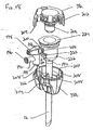
- the seal assembly generally includes a cap 86, a crown 88, bellows 90 used for radial seal movement, a female retaining ring 92, a protector 94, a plurality of reinforced seal segments 96 making up a seal body 98, a male retaining ring 100 and a bottom body 102.
- the reinforced seal segments 96 are positioned as described below in greater detail and mounted between the retaining rings 92,100 for creating a seal assembly 30 in accordance with the present invention.
- a reinforced seal segment 96 is shown.
- the proximal seal assembly 30 employs a plurality of reinforced seal segments 96 in creating a complete seal body 98.
- Each of the reinforced seal segments 96 is in the form of a partial cone, in particular, a cone extending about approximately 225 degrees. While the partial cone shape in accordance with a preferred embodiment of the present invention employs partial cones extending about approximately 225 degrees, partial cones of other shapes may be employed without departing from the sprit of the present invention. Although cone shaped seal segments are disclosed in accordance with a preferred embodiment, flat seal segments could be employed without departing from the spirit of the present invention.
- Each reinforced seal segment 96 is preferably manufactured from an elastomer of a cross linked polymer, such as, but not restricted to, polyisoprene or silicone.
- a cross linked polymer such as, but not restricted to, polyisoprene or silicone.
- each seal segment 96 includes a first side 104 and second side 106, and the first side 104 of each seal segment 96 is placed atop the second side 106 of the adjacent seal segment 96 to create a "woven" assembly of seal segments 96.
- the reinforced seal segments 96 are then bound together along their peripheral edges 108 to the male and female retaining rings 94, 100 to create a complete seal body 98.
- the bound seal segments 96 create a seal body 98 wherein the individual seal segments 96 are pushed outwardly upon the insertion of an instrument to create an opening for the passage of instruments and resilient move inwardly to close the opening upon the removal of instruments.
- the typical deformation of the reinforced seal segment 96 is shown with reference to Figure 3. The deformation is shown with the insertion of an instrument therethrough.
- each of the reinforced seal segments 96 is generally in the form of a cone with a portion of the cone cut away.
- the reinforced seal segment 96 includes a peripheral edge 108 secured to a central seal member 110.
- the peripheral edge 108 is substantially flat, lying in the same plane, while the central seal member 110 is formed in the shape of a section of a cone.
- the central seal member 110 is enhanced through the inclusion of a reinforcement pad 112 at a central position on the reinforced seal segment 96. That is, the reinforcement pad 112 is positioned between the peripheral edge and the free edge of the central seal member 110. More particularly, the reinforcement pad 112 is positioned at the tip of the cone defined by the central seal member 110 with edges of the reinforcement pad 112 being aligned with the free edge of the central seal member 110 at the tip of the cone.
- the reinforcement pad 112 is integrally formed with the remainder of the central seal member 110, but has a thickness that is approximately 2.5 times that of the nominal thickness of the central seal member 110.
- the reinforcement pad 112 of the central seal member 110 is formed with a thickness of approximately 0.017 inches, while the remainder of the central seal member 110 is formed with a thickness of approximately .007 inches. While thicknesses are disclosed above in accordance with a preferred embodiment of the present invention, different thickness may be employed without departing from the spirit of the present invention.
- the transition between the reinforcement pad 112 and the remainder of the central seal member 110 is achieved by tapering the central seal member 110 between the thickness of the reinforcement pad 112 and the remainder of the central seal member 110.
- transition could be done without transition regions; that is with a sharp transition.
- the preferred embodiment has no stress risers and allows the seal to seal better.
- the seal segments could have been made with the pad flat with no transition.
- the reinforcement pad 112 is general formed in a triangular configuration along the center of the arc defined by the reinforced seal segment 96.
- the reinforcement pad 112 occupies an arc of approximately 90 degrees along the central seal member 110.
- the shape and size of the reinforcement pad 112 may be varied to suit specific needs without departing from the spirit of the present invention.
- the reinforcement pad 112 should be shaped and dimensioned to cover an area that is intended for contact with instruments being passed through the trocar assembly 10.
- the reinforcement pad 112 is located on a portion of the central seal member 110 that is most likely to have direct contact with surgical instruments as they are inserted within the trocar cannula 12. In accordance with a preferred embodiment of the present invention, the reinforcement pad 112 is centrally located, as most surgical instruments will be inserted through the center of the trocar housing 16 and the trocar cannula 12.
- the angled surface that slopes from the reinforcement pad 112 to the nominal thickness of the central seal member 110 could be omitted and the reinforcement pad 112 could be smoothly blended into the nominal thickness of the central seal member 110 via continuous curvature.
- Low drag forces between the proximal seal assembly 30 and an insertion instrument are desirable.
- the present proximal seal assembly 30 permits the production of low drag forces without reducing seal durability. This is accomplished by reducing the seal thickness in conjunction with application of a reinforcement pad 112 as described above. As such, the reduction in thickness (in the area that is not contacting the instrument) is not accompanied with a reduction in seal durability as is common with prior art seal assemblies.
- the thin sections of the central seal member 110 surrounding the central reinforcement pad 112 allow for easy stretching of the remainder of the central seal member 110, thereby keeping drag forces on moving instruments to a minimum. Since the greatest strain occurs along the opening of the central seal member 110 when an instrument is present, and in accordance with a preferred embodiment, the reinforced seal segments 96 should be kept thin in any areas not contacting an instrument. This minimizes drag forces.
- the effective protection imparted by the present reinforcement pad 112 manifests itself in the proximal seal assembly 30 as follows. For a given deflection of the proximal seal assembly 30 due to initial contact with the tip of an instrument, the region defined by the reinforcement pad 112 of the proximal seal assembly 30 will have a relatively low strain when compared to the thinner portion of the central seal member 110 surrounding the reinforcement pad 112 due to the difference in thicknesses between the reinforcement pad 112 and the central seal member 110.
- This differential in strain is largest at the opening of the proximal seal assembly 30, where overall strains are highest
- the increased thickness of the reinforcement pad 112 will resist tenting, while the thin cross section of the remainder of the central seal member 110 not covered by the reinforcement pad 112 will allow the reinforcement pad 112 to easily deflect distally permitting the tip of the instrument to roll into the center of the proximal seal assembly 30.
- Resistance to tearing for the reinforced seal segment 96 is greatly increased as compared to prior art seal segments.
- the reinforcement pads 112 allow the reinforced seal segments 96 to protect themselves against sharp instruments independently of other peripheral protection devices. This protection is integral to the reinforced seal segments 96 themselves. Also the addition of reinforcement pads 112 at strategic locations (away from areas of high strain directly located at the point of likely sharp instrument contact) allows the reinforcement pads 112 to protect against puncture with little or no impact to seal performance. It does not increase peak instrument insertion forces or instrument drag forces. It is contemplated that the use of reinforcement pads 112 might be expanded beyond positioning at a central location, thereby offering some impact to peak instrument. insertion forces and instrument drag forces. However, due to the nature of the seal segments 96 and their greatly reduced strain relative to standard lip seals, this impact would likely yield a design that would easily outperform standard seal assemblies.
- the seal body 98 is formed with reinforcement pads 112 as described above it is still desirable to provide the proximal seal assembly 30 with a protector 92, as best shown in Figure 13.
- the protector 92 in accordance with a preferred embodiment of the present invention is positioned directly above the seal body 98.
- the protector 92 is composed of multiple overlapping protector segments 114 assembled in a woven arrangement to provide a complete protector 92.
- additional protector material is added (as a xesult of the overlapping arrangement) such that additional surface area of the seal body 98 may be protected as the protector segments 114 separate as an instrument is inserted into the seal.
- the protector 92 must be formulated to close gaps between protector segments 114 as an instrument is passed through the protector 92 and the seal body 98. This requires the addition of material along the opening of the protector 92.
- additional material is added to the protector 92 by weaving a plurality of protector segments 114.
- additional material is added to the protector 92 so as to widen each protector component while still allowing the protectors to fit within the coned seal profile.
- the extra material is wrapped behind the protector segment 114 to one side of each protector segment 114. This extra material is not visible when the protector segments 114 are viewed from above without an instrument inserted.
- the protector segments 114 in accordance with a preferred embodiment of the present invention are manufactured from molded elastomer, for example, pellethane. However, it is not intended that the protector segments 114 be limited to merely elastomers, but the protector segments 114 may be made from any type of material that contains the required properties and characteristics for the function described herein.
- protector segments 114 are arranged to create the protector 92. While four protector segments 114 are utilized in accordance with a preferred embodiment of the present invention, the protector 92 may ultimately be formed with different numbers of protector segments 114 without departing from the spirit of the present invention.
- Each protector segment 114 is semicircular when viewed from above and is generally in the form of a partial cone.
- Each of these protector segments 114 include a substantially round peripheral edge 116; a support wall 118 extending from the peripheral edge 116 and a cone shaped protector member 120.
- the cone shaped protector member 120 opposite the support wall 118 and the peripheral edge 116 defines straight shaped edge 121.
- the cone shaped protector member 120 spans an arc of approximately 180 degrees, while the support wall 118 and the peripheral edge 116 span an arc of approximately 120 degrees along the center of the cone shaped protector member 120.
- the limited arc spanned by the peripheral edge 116 and the support wall 118 reduces undesirable forces as instruments are moved past the proximal seal assembly 30.
- the outer peripheral edge 116 is adapted for positioning within the first housing member 36.
- the outer peripheral edge 116 further includes a series of apertures 122 that function as a means of attachment for the protector segments 114.
- the use of multiple protector segments 114 defining an arc of approximately 180 degrees results in a reduction in hoop stresses by providing a protector 92 composed of a series of protector segments 114 which readily bend in and out radially as instruments are inserted therethrough.
- Each protector segment 114 includes a first section 124 and a second section 126 defining opposite sides of the protector segment 114.
- the four individual protector segments 114 are combined in a woven arrangement to create a complete protector 92 that fully protects the underlying seal body 98. That is, the protector 92 is assembled by placing the first section 124 of a first protector segment 114 upon the second section 126 of a second protector segment 114.
- the first section 124 of the second protector segment 114 is subsequently placed upon the second section 126 of a third protector segment 114, the first section 124 of the third protector segment 114 is placed upon the second section 126 of a fourth protector segment 114 and the first section 124 of the fourth protector segment 114 is placed upon the second section 126 of the first protector segment 114 like one folds the final flap of a box lid.
- the protector segments 114 are ultimately held together through the application of the crown 88 and female retaining ring 94.
- Retaining members are well known to those skilled in the art and a variety of retaining members may be employed within the spirit of the present invention.
- cone shaped protector members 120 movement of the cone shaped protector members 120 relative to the peripheral edge 116 and the support wall 118 is subject to resistance based upon the various orientations of the connected components. As such, the cone shaped protector members 120 might be susceptible to buckling as instruments are moved through the proximal seal assembly 30.
- This resistance to movement is minimized due to the limited arc of the peripheral edge 116 and the support wall 118 as discussed above.
- the resistance is further minimized by forming a central slot 128 with the peripheral edge 116 and/of the support wall 118. This slot 128 functions to reduce buckling as the protector members 120 may move the same distance with less resistance.
- the protector 92 By weaving the protector 92 additional material may be added to each protector segment 114 while still allowing the distal end of the protector 92 to fit into the apex of the cone shaped seal body 98. This is accomplished by having the extra material added to the protector segments 114 wrap behind the protector segment 114 adjacent thereto. This extra material allows for improved coverage of the seal body 98, especially when instruments are inserted at an angle relative to the proximal seal assembly 30. Finally, weaving of the protector 92 has minimal, if any effects on the instrument drag force as it is moved in and out of the proximal seal assembly 30. This is a result of the fact that the protector segments 114 move easily relative to each other.
- each protector segment 114 In practice, and due to the extra material added to each protector segment 114, as an instrument is inserted into the protector 92, the protector segments 114 spread, exposing the additional protector material positioned behind adjacent protector segments 114. This additional material continues to cover the seal body 98 as the protector segments 114 bend relative to one another. The less seal body 98 material exposed to the inserted instrument, the better the protection offered by the present protector 92. While the present protector 92 offers good seal protection, additional protector segments 114 can be added although they might cause an increase in the instrument drag forces. This may be balanced, however, by thinning the protector segments 114 to make them more flexible or by adding lubricant to the protector segments 114 and/or the seal body 98.
- a duckbill seal assembly 32 is housed within the second housing member 38.
- the duckbill seal assembly 32 in accordance with a preferred embodiment of the present invention is disclosed.
- the duckbill seal assembly 32 includes first and second seal bodies 130, 132 extending from a circumferential flange member 134 shaped and dimensioned for mounting within the second housing member 38.
- Each of the first and second seal bodies 130, 132 includes an upper surface 136, 138 and a lower surface 140, 142.
- the upper surface 136, 138 and the lower surface 140,142 are generally mirror images as the first and second seal bodies 130,132 maintain a substantially consistent thickness along its entire length with the exception of the reinforcing rib along the upper surface 136,138.
- the first and second seal bodies 130, 132 are mounted within the trocar housing 16 for movement as an instrument is passed therethrough.
- the proximal end of each of the first and second seal bodies 130, 132 is coupled to the trocar housing 16 via the circumferential flange 134, while the distal ends of the first and second seal bodies 130, 132 intersect to define an abutment face 144.
- the abutment face 144 is generally positioned within the center of the trocar housing 16 to permit the passage of an instrument therethrough, while in the absence of such an instrument the abutment face 144 is closed via the resilience of the first and second bodies 130, 132 as they are biased under the pressure generated from the body cavity in which the trocar assembly 10 is positioned. For example, biased under the pressure from the abdominal insufflation gas pressure. This pressure causes the duckbill seal assembly 32 to move to a closed position with the distal ends of the first and second seal bodies 130,132 in contact.
- the seal bodies 130, 132 may be formed with ribs (not shown) on the upper surface 136, 138 so as to enhance the stability of the seal bodies 130,132 when contacted with an instrument.
- the ribs also provide a path for instruments to ride upon as they pass through the duckbill seal assembly 32.
- the ribs also lower friction as the instruments pass through the duckbill seal assembly 32 because it provides less surface area on which an instrument may ride, and thus greater contact pressure between the seal and the instrument may be applied.
- the first and second seal bodies 130,132 will now be described with reference to the first seal body 130. Those skilled in the art will appreciate that the first and second seal bodies 130, 132 are identical and the following descriptions equally relates to the second seal body 132.
- the seal body 130 is formed with a first section 148 and a second section 150 angularly oriented relative to each other and a transverse plane 146 extending through the circumferential flange 134.
- the transverse plane 146 is substantially perpendicular to the longitudinal axis extending through the duckbill seal assembly 32.
- the first and second sections 148, 150 extend from a proximal end of the seal body 130 respectively toward a distal end of the seal body 130.
- the first section 148 is positioned adjacent the proximal end of the seal body 130 adjacent the wall of the circumferential flange 134 and the trocar housing 16.
- the first section 148 moves only slightly as an instrument is inserted therethrough.
- the second section 150 is positioned adjacent the distal end of the seal body 130 and adjacent the abutment face 144. The second section 150 freely moves as an instrument is inserted therethrough.
- first and second sections lie at angles between 0 degrees and 90 degrees relative to the transverse plane. Assuming the transverse plane 146 lies in a horizontal plane, and in accordance with a preferred embodiment of the present invention, the first section 148, which begins at the proximal end of the seal body 130, is oriented at approximately a 30 degree angle relative to the horizontal plane in which the transverse plane 146 lies. The second section 150, which extends to the distal end of the seal body 130, is thereafter oriented at a 45 degree angle relative to the horizontal plane.
- the angles disclosed above in accordance with a preferred embodiment of the present invention may be varied without departing from the spirit of the present invention.
- the chosen angles are based upon the trade off between the durability of the seal bodies (improves at greater angles as likelihood of an instrument pointedly engaging the seal, i.e. tenting is less likely at greater angles) and the height of the seal (greater angles dictate greater height).
- the second section 150 may be formed at an angle of approximately 40 degrees to approximately 50 degrees while providing for the many advantages contemplated in accordance with the present duckbill seal assembly 32.
- the height or profile of the duckbill seal assembly 32 is important as reductions in size allow for improved instrument access because the length of the trocar housing 16 may be consequently made smaller. Smaller housings provide surgeons with greater access within the body cavity and thus are very desirable.
- first and second sections 148, 150 in implementing the present invention, additional sections may be employed without departing from the spirit of the present invention.
- present duckbill seal bodies 130, 132 may be constructed with an infinite number of angles, that is, with a continuous curving surface, without departing from the spirit of the present invention.
- the wall angle should be maintained low (for example, 30 degrees) where instruments do not ordinarily contact the seal bodies 130, 132 of the duckbill seal assembly 32 and increase to a high value (for example, 45 degrees) where instruments customarily contact the wall surface of the seal bodies 130, 132.
- first and second sections 148, 150 By orienting first and second sections 148, 150 in this manner, that is, by varying the wall angles along the extent of the seal bodies 130, 132, tear resistance is improved without adjusting the overall height of the duckbill seal assembly 32.
- the overall height of the duckbill seal assembly 32, and ultimately the trocar assembly 10 may be minimized, while accommodating proper seal function.
- the application of a high wall angle at the location where instruments customarily contact the seal bodies 130, 132 minimizes normal forces contacting the duckbill seal assembly 32 and consequently minimizes the potential for tearing of the duckbill seal assembly 32.
- the height of the trocar sleeve 44 is a critical issue due to its impact on ergonomics.
- the duckbill drag, durability, and sealing functions must all be balanced with the need for minimized trocar sleeve 44 height.
- the height of the duckbill seal assembly 32 is minimized by using two wall angles.
- the wall angle along the first section 148 is shallow to minimize the height.
- the wall angle becomes steeper at the second section 150. This steeper wall provides a lower attack angle with respect to an inserted instrument to maximize durability.
- the sealing function is improved due to the greater closure forces from the abdominal gas pressures acting on the second section with the lower attack angle due to the steeper wall, as compared with the angle of the first section 148.
- the duckbill seal assembly 32 is an elastomer or a cross linked polymer such as, but not restricted to, polyisoprene or silicone.
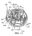
- the endoscope lock assembly 152 generally includes a cam mechanism that retains an endoscope within a trocar sleeve 44 and/or obturator 14 during insertion of trocar assembly 10.
- the mechanism uses a cam to compress an elastomeric block 154 against the endoscope.
- the elastomeric block 154 then grips the endoscope tightly to prevent undesired motion of the endoscope as the surgeon is visualizing the tissue layers during the trocar assembly insertion.
- the cam mechanism provides for the ability to retain the endoscope while resisting both torque and axial loads, provides for acceptable endoscope retention after repeated throws of the cam lever 156, provides low ergonomic forces to actuate the cam lever 156, provides for compatibility with a wide range of endoscope sizes, facilitates intuitive use and has a long term shelf life stability.
- the cam mechanism that retains the endoscope within a trocar assembly 10 uses a cam surface 158 to compress the elastomeric block 154 against the endoscope.
- the elastomeric block 154 then grips the endoscope tightly to prevent undesired motion of the endoscope as the surgeon is visualizing the tissue layers during the trocar assembly insertion.
- the lock assembly 152 includes a housing 160 having a tube 162 extending therefrom.
- the tube 162 is aligned with an aperture extending therethrough.
- the tube is formed with a sharp tip and may be utilized as an obturator in accordance with the present invention.
- the tube 162 and the aperture are shaped and dimensioned for the extension of an endoscope therethrough.
- the tube 162 is shaped and dimensioned to extend through the trocar cannula 12 such that the lock assembly 152, including the tube 162, maybe selectively secured to the trocar sleeve 44 for the use of an endoscope.
- Attachment of the lock assembly 152 to the trocar first housing member 36 is achieved via mating latches 164, 166 formed on both the underside of the lock assembly housing 160 and the upper surface 168 of the first housing member 36.
- the latches 164, 166 permit selective attachment and release of the lock assembly 152 to the trocar housing 16. While a specific latching structure is disclosed in accordance with a preferred embodiment of the present invention, other latching structures may be utilized without departing from the spirit of the present invention.
- the lock assembly housing 160 includes a camming based locking mechanism.
- the locking mechanism is composed of a cam lever 156 and an elastomeric block 154.
- the cam lever 156 includes a first end 170 that is pivotally secured to the housing 160 and a free second end 172 that is adapted for user actuation.
- the cam lever 156 may be freely moved between a locking position in which the cam lever 156 is rotated inwardly and a release position in which the cam lever 156 is rotated outwardly.
- Camming action in accordance with the present invention is provided by a camming surface 158 adjacent the first end 170 of the cam lever 156.
- the camming surface 158 is shaped and dimensioned to engage the elastomeric block 154 for selectively locking an endoscope within the lock assembly 152.
- the elastomeric block 154 it is housed within the body of the lock assembly housing 160 and includes a forward concave wall 174 shaped and dimensioned for engaging an endoscope passing through the housing aperture.
- the elastomeric block 154 further includes first and second side walls 176, 178, wherein each side wall 176, 178 includes a notch 180 for engagement with a channel 182 formed within the body of the housing 160.
- the channel 182 and notch 180 interact to allow lateral movement of the elastomeric block 154 in a manner that is described below in greater detail.
- the housing 160 further includes upper and lower retaining members 184,186 for securely preventing upward or downward motion of the elastomeric block 154 within the housing 160.
- the elastomeric block 154 includes a rear wall 188 opposite the forward concave wall 174. The rear wall 188 is shaped and dimensioned for engagement with the camming surface 158 of the cam lever 156.
- the elastomeric block 154 and the camming surface 158 are shaped to eliminate forceful contact, and in particular eliminate any contact, between the elastomeric block 154 and the camming surface 158 until such a time that an endoscope is positioned with the aperture of the lock assembly housing 160.
- the elastomeric block 154 is moved toward the cam lever 156 to such a degree that the elastomeric block 154 comes into proximity of the camming surface 158 for locking of the endoscope within the aperture once the cam lever is actuated,
- the lock assembly 152 is used in the following manner.
- the elastomeric block 154 sits within the lock assembly housing 160 underneath the cam lever 156, which may be either open or closed during long-term storage.
- the elastomeric block is purposefully not in contact with the cam lever 156 at this point to avoid any loads on the elastomeric block 154 that could affect the lock assembly's 152 performance after long-term storage.
- the surgeon then opens the cam lever 156 if it was originally closed.
- An endoscope is inserted into the lock assembly 154.
- the endoscope hits a chamfered surface 190 on the concave wall 174 of the elastomeric block 154. This lifts the elastomeric block 154 upward into the proximity of the cam lever 156.
- the elastomeric block 154 then rests on top of the endoscope for the rest of its use.
- the cam lever 156 is then actuated, which compresses the compressible scope lock onto the endoscope.
- the compliance of the elastomeric block 154, along with its high coefficient of friction, allows the lock assembly 152 to be compatible with a wide range of endoscope sizes while minimizing ergonomic force requirements.
- the elastonieric block 154 is then constrained from excessive sideways or axial motion by surrounding components 182, 184, 186 that limit its motion as axial and torsional loads are applied to the endoscope.
- the trocar sleeve 44 is composed of a trocar housing 16 and a trocar cannula 12 extending from the trocar housing 16.
- the trocar assembly 10 also includes a stop-cock valve 192 for allowing and preventing the passage of an insufflation fluid, e.g. carbon dioxide, through flexible tubing into a portion of the trocar housing 16 and the trocar cannula 12.
- an insufflation fluid e.g. carbon dioxide
- the trocar cannula 12 and the trocar housing 16 are mechanically interfitted to form the trocar sleeve 44. At least a portion of the trocar cannula 12 sits within a second housing member base 38b of the second housing member 38 with a second housing member cover 38a sitting over the trocar cannula 12 for securing the at least a portion of the trocar cannula 12 within the second housing member base 38b.
- the trocar cannula 12 is sized so that when the trocar obturator 14 extends completely through it and beyond, insufflation fluid, which passes through the stop-cock valve 192 and the trocar housing 16, can pass through an annular opening created between the trocar cannula 12 and the trocar obturator 14 by the slightly greater size of the internal diameter of the trocar cannula 12 in relation to the outer diameter of the hollow shaft of the trocar obturator 14.
- the present invention provides a mechanism for mechanically assembling the trocar cannula 12, trocar housing 16 and stop-cock valve 192 without the need for adhesive and/or curing techniques.
- the second housing member 38 of the trocar housing 16, trocar cannula 12 and stop-cock valve 192 are formed as separate components that may be assembled in a convenient and reliable manner.
- the trocar sleeve 44 when, fully assembled, comprises a stop-cock valve 192, a second housing member 38 composed of a second housing member cover 38a and a second housing member base 38b; and a trocar cannula 12.
- the various components of the trocar sleeve 44 are mechanically assembled by interfitting the components in manner that is described below in greater detail.
- the trocar cannula 12 fits within the second housing member base 38b with the stop-cock valve 192 positioned therebetween.
- the second housing member cover 38a fits over the stop-cock valve 192, second housing member base 38b and trocar cannula 12 to retain the various components together and provided a surface upon which the first housing member 36 may be selectively mounted.
- the stop-cock valve 192 includes alignment wings 194, a flow opening 196, and a valve leveir 198.
- the valve lever 198 includes a stop latch 200.
- the second housing member cover 38a includes a hexagonal bore 202, a cover rim 204, and a second housing member cover seal 206.
- the second housing member base 38b includes friction posts 208, vanes 210, a housing rim 212, a clearance 214 for the stop-cock valve 192 and alignment wings 194.
- the second housing member base 38b further includes alignment ribs 216 and a latching face 218.
- the trocar cannula 12 includes an inlet nipple 220, alignment tabs 222, and a housing seal 224.
- the stop-cock valve 192 is inserted into the clearance 214 of the second housing member base 38b.
- the trocar cannula 12 inserts through the opening of the second housing member base 38b.
- the alignment tabs 222 abut the vanes 210 securing the trocar cannula 12 in a desired orientation with respect to the second housing member base 38b once the trocar cannula 12 is inserted into the second housing member base 38b.
- the cover rim 204 mates with the housing rim 212.
- the cover rim 204 also serves to hold the valve lever 198 on the stop-cock valve 192 as well as hold the stop-cock valve 192 with the valve lever 198 in position.
- valve lever 198 in a maximum flow allowance position, i.e., fully open, has the stop latch 200 abut onto the latching face 218 of the second housing member base 38b. This means an operator of the valve lever 198 can sense when the valve lever 198 is in a fully open position by abutting latch face 218 and the valve lever 198 stays in the fully open position. The operator does not have to guess that the valve lever 198 is in the fully open position, and the valve lever 198 stays in the fully open position.
- trocar assembly 44 eliminates the need for adhesives to join the stop-cock valve 192 and the second housing member cover 38a, and the second housing member base 38b and the trocar cannula 12. This is an advantage over prior art.
- the trocar sleeve 44' includes a stop-cock valve 192'; a second housing member cover 38a', and a second housing member base 38b'.
- the trocar sleeve 44' also includes a trocar cannula 12' which is substantially similar to the trocar cannula 12 disclosed in accordance with the prior embodiment.
- the stop-cock valve 192' comprises a valve tube taper lock extension 226', a friction post 228' and a valve lever 198'.
- the second housing member base 38b' comprises an extension clearance 230', and a friction post hexagonal bore 232'.
- valve tube taper lock extension 226' of the stop-cock valve 192' locks into the extension clearance 230' of the second housing member base 38b'.
- the friction post 228' of the stop-cock valve 192' fits into the friction post hexagonal bore 230' of the second housing member base 38b', securing the vertical alignment of the stop-cock valve 192' with respect to the second housing member base 38b'.
- the trocar sleeve 44" comprises a second housing member cover 38a", a second housing member base 38b", and a stop-cock valve 192".
- the trocar sleeve 44" also includes a trocar cannula 12" which is substantially similar to the trocar cannula 12 disclosed in accordance with the prior embodiment.
- the stop-cock valve 192" comprises a locking groove boss 234", a valve tube extension 236", and a locking groove 238".
- the second housing member cover 38a" includes a locking tongue 240".
- the second housing member base 38b" also comprises a valve tube extension aperture 242" and a boss clearance 244".
- the valve tube extension 236" of the stop-cock valve 192" inserts and locks, by friction fit or taper-lock, into the valve tube extension aperture 242" of the second housing member base 38b".
- the locking groove boss 234" of the stop-cock valve 192" locks into the boss clearance 244". This serves to assist in securing the stop-cock valve 192" in the second housing member base 38b".
- the stop-cock valve 192 is mechanically coupled to the trocar sleeve 44 via tapered surfaces shaped and dimensioned for frictional engagement.
- the outlet tube 250 of the stop-cock valve 192 is formed with a tapered lock surface along the exterior of its distal end.
- the trocar cannula 12 is formed with an inlet nipple 220, adapted for secure coupling with the tapered lock surface of the outlet tube 250 of the stop-cock valve 192.
- the tapered lock mechanical feature includes a self holding 2.0 degrees +/- 1.0 degrees angle, which is firmly seated into the trocar housing inlet nipple 220. The result of this mechanical connection is considerable frictional resistance to rotational and linear pull out forces.
- the taper lock feature may be provided with a post and hex socket interlock, tongue and groove interlock and/or a snap fit interlock.
- rotation of the stop-cock valve 192 is minimized by the inclusion of a retaining pin 204 located on the second housing member cover 38a that extends downwardly into the aperture 256 formed in the top of the valve lever 198.
- the retaining pin 204 stabilizes the stop-cock valve 192 and prevents rotation as the valve lever 198 of the stop-cock valve 192 is actuated.
- the trocar sleeve includes a stop-cock valve 192.
- the stop-cock valve 192 is mounted within a recess formed in the trocar sleeve 44. As such, the stop-cock valve 192 recessed within the outer surface of the second housing member base 38b, and ultimately the trocar housing 16.
- the valve lever 198 is further positioned above the body of the stop-cock valve 192; that is, the valve lever 198 used in actuating the stop-cock valve 192 is positioned on the top surface of the stop-cock valve 192 instead of underneath as with trocar assemblies currently in the marketplace.
- the present trocar assembly 10 provides for the removal of the stop-cock valve 192 from a potentially obstructing view while simultaneously placing the valve lever 198 in a highly accessible position.
- this orientation minimizes the obstructions caused by users gripping the stop-cock valve 192 of the trocar assembly 10 for insertion. A more comfortable grip is, therefore, provided, as the stop-cock valve 192 no longer protrudes from the surface of the trocar housing 16.
- the present low profile stop-cock valve 192 structure further helps to prevent compromising desired hand positions.
- the present stop-cock valve 192 orientation also helps to prevent accidental manipulation during procedures. Accidental manipulation by movement of the trocar sleeve 44 into contact with a patient is a common occurrence that results in desufflation of the body cavity and can lead to frustrating and even dangerous situations when the medical professional's field of view is compromised.
- valve lever 198 with a curved surface substantially conforming to that of the trocar housing 16.
- longitudinal axis along the handle portion of the valve lever 198 is offset from the pivot point about which the valve lever 198 rotates so as to enhance recessing of the stop-cock valve 192.
- Controlled rotation of the valve lever 198 of the stop-cock valve 192 is achieved through the positioning of the stop-cock valve 192. within a recess formed in the trocar sleeve 44, more specifically, the trocar housing 16.
- valve lever 198 of the stop-cock valve 192 includes a stop latch 200 located on the valve 198 which provides tactile feedback as to when the valve lever 198 is in the open position, i.e., the through holes located on the valve lever 198 and valve body 199 are aligned.
- the design feature resembles a cantilever beam located on the end of the valve lever 198 opposite the user end.
- valve lever 198 As the valve lever 198 is rotated from the closed position to the open position within the trocar assembly 10, the cantilever rotational stop latch 200 contacts the trocar housing 16 providing tactile feedback that the valve lever 198 is in the fully opened position. In the fully opened position, the valve lever 198 and valve body 199 through holes are aligned allowing for optimal CO 2 flow.
- the cantilever rotational stop latch 200 feature provides the surgeon with tactile feedback to ensure that the stop-cock valve 192 is in the open position. This will provide the optimal flow of CO 2 flow throughout the surgical case.
- control of the valve lever 198 via the cantilever rotational stop latch 200 helps in alignment of the stop-cock valve 192 through hole 196. Misalignment of through holes 196 is commonly caused by lack of tactile feedback to the surgeon that the valve lever 198 is in the fully opened position.
- a strengthening gusset 264 is located on the backside of the cantilever rotational stop latch 260 to prevent over-rotation of the valve lever 198 by bending the valve lever 198. This can be seen in Figure 17 and 18. Over-rotation would create misalignment of the through holes.
- the separate trocar cannula 12 design described above provides for interchangeable outer housing capabilities. As such, the industrial design outside shape can be readily changed and updated without changing the internal structure of the trocar sleeve.
- assembly of the trocar cannula 12 to the trocar housing 16 joint system eliminates the need for ultrasonic welding.
- the present assembly method makes the device stronger by molding the trocar cannula 12 in one part.
- prior designs utilized ultrasonic weld joints to assemble the trocar cannula 12 to the trocar housing 16.
- the present assembly structure eliminates the use of such joints and, therefore; provides no opportunity for failure of the ultrasonic weld joints.
- the trocar housing 16 is provided with crush ribs 266 along its internal surface. These crush ribs 266 center the trocar cannula 12 within the trocar housing 16. They also take up small variations in tolerances making the size of the trocar cannula 12 during manufacture less important and allowing for inherent variations during the molding process.
- the crush ribs 266 further prevent rotation of the trocar cannula 12 within the trocar housing 16. This is achieved as the crush ribs 266 extend into the sides of the trocar cannula 12 thereby preventing relative rotation between the trocar cannula 12 and the trocar housing 16.
- trocar housing 16 and trocar cannula 12 are rather simple in construction, the molding process is simplified by eliminating excessive core details on the injection mold tool. In addition, assembly of the system is easy as compared to prior designs as all of the components making up the sleeve assembly can be assembled in a top down manner.
- the taper lock with dual redundant locking features helps to prevent the stop-cock valve 192 from falling off the trocar sleeve 44.
- the taper lock provides an airtight assembly without the use of adhesive or welding.
- the stop-cock valve 192 is provided with various lock surfaces preventing rotation of the stop-cock valve 192, for example, post and socket, tongue and groove, wings on ribs, etc.
- the wings are trapped behind the trocar housing 16; eliminating the possibility for removal of the stop-cock valve 192 from the trocar sleeve 44.
- crush ribs 266 are utilized in holding the wings tight onto the trocar cannula 12.
- the low profile stop-cock valve 192 structure with a valve lever 198 positioned above the stop-cock valve 192 allows for alignment of the stop-cock valve 192 to provide optimal air flow and offers users a tactile feedback for optimizing alignment.
Abstract
Description
- This application is based upon U.S. Provisional Patent Application No.60/506,782, filed September 30, 2003, entitled ''WOVEN PROTECTOR FOR TROCAR SEAL ASSEMBLY", which is cuxrently pending.
- The invention relates to protectors for wse in conjunction with the sealing assemblies of trocars. More particularly, the invention relates to a woven protector for use in conjunction with a trocar sealing assembly.
- A trocar assembly is a surgical instrument that is used to gain access to a body cavity. A trocar assembly generally comprises two major components, a trocar sleeve, composed of a trocar housing and a trocar cannula, and a trocar obturator. The trocar cannula, having the trocar obturator inserted therethrough, is directed through the skin to access a body cavity. Once the body cavity is accessed, laparoscopic or arthroscopic surgery and endoscopic procedures may be performed. In order to penetrate the skin, the distal end of the trocar cannula is placed against the skin that has been previously cut with a scalpel. The trocar obturator is then used to penetrate the skin and access the body cavity. By applying pressure against the proximal end of the obturator, the point of the obturator is forced through the skin until it enters the body cavity. The trocar cannula is inserted through the perforation made by the obturator and the obturator is withdrawn, leaving the trocar cannula as an access way to the body cavity.
- The proximal end portion of the trocar cannula is typically joined to a trocar housing that defines a chamber having an open distal end portion in communication with the interior lumen defined by the trocar cannula. An obturator, or other elongated surgical instruments or tools, axially extend into and are withdrawn from the trocar cannula through the proximal end portion of the chamber defined by the trocar housing.
- It is common for a sealing arrangement or sealing device to be used in association with the trocar cannula and trocar housing to prevent the escape of fluid or gas during endoscopic procedures. During an endoscopic surgical procedure, the internal gas pressure must be maintained in order to successfully complete the procedure. In order to maintain the internal gas pressure while instruments are passed into and out of the trocar assemblies positioned in the abdominal cavity, sealing devices are required for both the obturators and instruments passing through the trocar cannula.
- Seals must also offer good tear resistance, resistance to snagging and low friction with respect to associated seals and the insertion or removal of surgical instruments. Angular insertion of instruments relative to the central axis of the trocar cannula, instrument tip sharpness and end effecter geometry are driving factors in trocar seal failures. These three factors can cause "tenting" of the seal material. Once tenting occurs, continued distal motion of the penetrating instrument may result in seal tearing.
- As such, a need exists for a protector capable of protecting the seal body as an obturator or instrument is passed through the trocar cannula. The present invention provides such a protector.
- It is, therefore, an object of the present invention to provide a seal assembly for use in conjunction with a trocar assembly. The seal assembly includes a seal body adapted for sealing about an instrument inserted through the trocar assembly. The seal assembly also includes a protector adjacent the seal body for protecting the seal body from instruments passing through the seal body. The protector comprises a plurality of protector segments woven together in a non-planar arrangement.
- It is also an object of the present invention to provide a trocar assembly with a trocar cannula having a proximal end and distal end and a trocar housing coupled to the proximal end of the trocar cannula for receiving and guiding an obturator through the trocar cannula. The trocar housing includes an open proximal end portion defining an opening provided with a proximal seal assembly and a distal seal assembly. The proximal seal assembly includes a seal body adapted for sealing about an instrument inserted through the trocar assembly and a protector adjacent the seal body for protecting the seal body from instruments passing through the seal body. The protector comprises a plurality of protector segments woven together in a non-planar arrangement.
- Other objects and advantages of the present invention will become apparent from the following detailed description when viewed in conjunction with the accompanying drawings, which set forth certain embodiments of the invention.
-
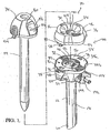
- Figure 1 is a perspective view of a trocar assembly in accordance with the present invention.
- Figure 2 is an exploded view of the trocar assembly shown in Figure 1.
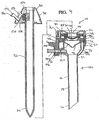
- Figure 3 is a cross sectional view of the trocar assembly shown in Figure 1.
- Figure 4 is an exploded cross sectional view of the trocar assembly shown in Figure 1.
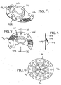
- Figure 5 is a detailed view of the rotary latch mechanism utilized in accordance with the present trocar assembly.
- Figure 6 is an exploded view of the proximal seal assembly in accordance with the present trocar assembly.
- Figure 7 is a bottom perspective view of a seal segment.
- Figure 8 is a top view of a seal segment.
- Figure 9 is a cross sectional view along the line IX-IX in Figure 8.
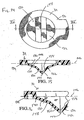
- Figure 10 is a seal body composed of four seal segments as shown in Figures 7, 8 and 9.
- Figure 11 is a top perspective view of a protector segment.
- Figure 12 is a bottom view of a protector segment.
- Figure 13 is protector composed of four protector segments as shown in Figures 11 and 12.
- Figure 14 is a top perspective view of a duckbill seal assembly in accordance with the present invention.
- Figure 15 is a cross sectional view along the line XV-XV of Figure 14.
- Figure 16 is a partial cross sectional view along the line XV-XV of Figure 14.
- Figure 17 is an exploded view of the trocar sleeve in accordance with the present invention.
- Figure 18 is a further exploded view of the trocar sleeve in accordance with the present invention.
- Figure 19 is an assembled perspective view of the trocar sleeve shown in Figures 17 and 18.
- Figure 20 is a rear perspective view of the trocar sleeve shown in Figures 17 and 18.
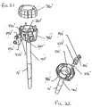
- Figure 21 is an exploded view in accordance with an alternate embodiment of the trocar sleeve.
- Figure 22 is a partial exploded view in accordance with an alternate embodiment of the trocar sleeve as shown in Figure 19.
- Figures 23 and 24 are exploded views of a further embodiment of the trocar sleeve.
- Figure 25 is a detailed view of the endoscopic lock mechanism.
-
- The detailed embodiments of the present invention are disclosed herein. It should be understood, however, that the disclosed embodiments are merely exemplary of the invention, which may be embodied in various forms. Therefore, the details disclosed herein are not to be interpreted as limiting, but merely as the basis for the claims and as a basis for teaching one skilled in the art how to make and/or use the invention.
- A protector for a trocar seal assembly in accordance with the present invention is disclosed. The protector provides for improved resistance to tearing by protecting the seal from direct contact with obturators and tools as they pass through the trocar cannula. As those skilled in the art will certainly appreciate, the present protector may be adapted for use with a variety of trocar assemblies without departing from the spirit of the present invention.
- Referring to Figures 1 to 5, the
trocar assembly 10 generally includes atrocar cannula 12, atrocar obturator 14, and a trocar housing (or handle) 16. Thetrocar cannula 12 defines aninterior lumen 18 having an opendistal end portion 20 and an openproximal end portion 22. Theproximal end portion 22 extends into and is mounted in thedistal end portion 24 oftrocar housing 16. Thetrocar housing 16 has an openproximal end portion 26 that defines anopening 28. Theopening 28 is provided with aproximal seal assembly 30 constructed in accordance with the present invention and described in detail hereinbelow. Theopening 28 is further provided with aduckbill seal assembly 32 positioned beneath theproximal seal assembly 28. While the present seal assembly is disclosed as a proximal seal assembly forming part of a dual sealing system, the present seal assembly may be utilized in a single seal system without departing from the spirit of the present invention. - In general, the
trocar sleeve 44 is composed of atrocar cannula 12 and atrocar housing 16. Thetrocar housing 16 includes afirst housing member 36 and asecond housing member 38. Thesecond housing member 38 is ultimately composed of a secondhousing member cover 38a and a secondhousing member base 38b. Although, thehousing 16 is disclosed as two components it is contemplated that a single component could be used without departing from the spirit of the present invention. The two component housing shown, aids in removal of specimens. - The
trocar obturator 14 is slidable in and removable from within thetrocar cannula 12 and is inserted into thetrocar housing 16 and thetrocar cannula 12 through theproximal seal assembly 30, theduckbill seal assembly 32 and theopening 28 of thetrocar housing 16. An obturator handle 34 is provided at the proximal end of thetrocar obturator 14 and a point or blade (not shown) is formed at the distal end thereof. As is well known in the art, theproximal seal assembly 30 cooperates with the exterior of the instruments (for example, trocar obturators and other tools adapted for use in conjunction with trocar based procedures) extending through thetrocar sleeve 44 to sealingly engage the exterior surface thereof and thereby preclude the passage of fluids through thetrocar housing 16. - With regard to the
trocar housing 16 and with reference to Figures 1 to 5, thetrocar housing 16 is constructed of afirst housing member 36 and asecond housing member 38 which are selectively coupled for reasons that will be discussed below in greater detail. The first andsecond housing members apertures trocar housing 16. - As those skilled in the art will certainly appreciate, it is important that the first and
second housing members trocar sleeve 44 into the abdominal wall, as well as during the normal course of a procedure. However, it is also desirable to remove thefirst housing member 36 during the removal of a specimen, for example, from the abdominal cavity. The removal of thefirst housing member 36 allows the specimen to pass through only theduckbill seal assembly 32, instead of passing through both theduckbill seal assembly 32 and theproximal seal assembly 30. This provides for easier specimen removal and less trauma to the specimen during the removal process. - The
first housing member 36 supports the proximal sealingassembly 30 and sits atop thesecond housing member 38 in which theduckbill seal assembly 32 is mounted. Thefirst housing member 36 includes anaperture 40 extending therethrough. Theproximal seal assembly 30 is positioned within theaperture 40 of thefirst housing member 36. - As to the
second housing member 38, thesecond housing member 38 includes anaperture 42 extending therethrough. Theduckbill seal assembly 32 is positioned within theaperture 42 of thesecond housing member 38 adjacent thetop surface 50 of thesecond housing member 38. In fact, and for reasons which will be discussed below in greater detail, theperipheral tim 52 of theduckbill seal assembly 32 is positioned directly adjacent thetop surface 50 of thesecond housing member 38 for engagement with thelower surface 54 of thefirst housing member 36. - Connection of the
first housing member 36 to thesecond housing member 38 is facilitated by arotary latch mechanism 56. In particular, thefirst housing member 36 includes first and second downwardly extendingarms 58. Each of the downwardly extendingarms 58 includes a downwardly facingcamming surface 60 and an outwardly facing latchingsurface 62. - The
second housing member 38 similarly includes a latchingring 64 with first and second latch members 66 for respectively engaging the respective latching surfaces 62 of the first and second downwardly extendingarms 58 of thefirst housing member 36. The latchingring 64 is axially aligned with the central axis of thetrocar sleeve 44 and lies in an annular groove 68 around the perimeter of theduckbill seal assembly 32. Although the latchingring 64 in accordance with a preferred embodiment rotates about a central axis of thetrocar housing 16, the latchingring 64 may rotate about other axes without departing from the spirit of the present invention. The latchingring 64 is capable of rotating about the central axis of thetrocar sleeve 44, but is attached to thetrocar housing 16 by aspring 70. Thespring 70 holds the latchingring 64 in a locked position with a small amount of preloaded bias. However, thespring 70 allows rotation of the latchingring 64 during the attachment of thefirst housing member 36. The first and second latch members 66 respectively include upwardly facing camming surfaces 72 that interface with downwardly facing camming surfaces 60 of the first and second downwardly extendingarms 58 of thefirst housing member 36. - The first and second latch members 66 each include an upwardly facing
camming surface 72 shaped and dimensioned to respectively engage the camming surfaces 60 of the downwardly extendingarms 58. Similarly, the first and second latch members 66 include inwardly facing latching surfaces 74 shaped and dimensioned for engaging the outwardly facing latching surfaces 62 of the first and second downwardly extendingarms 58. - In practice, latching of the first and
second housing members arms 58 through holes 76 formed in thetop surface 50 of thesecond housing member 38. As the first and second downwardly extendingarms 58 extend through the respective holes 76 adjacent the first and second latch members 66 of the latchingring 64, the camming surfaces 60 of the respective first and second downwardly extendingarms 58 engage the camming surfaces 72 of the first and second latch members 66. The engagement causes thelatch ring 64 to rotate in a manner permitting the first and second downwardly extendingarms 58 to extend past the first and second latch members 66. This rotation is against the bias provided by thespring 70. - Once the first and second downwardly extending
arms 58 move past the first and second latch members 66, thespring 70 biasing the latchingring 64 causes the latchingring 64 to return to its original position and the outwardly facing latching surfaces 62 of thefirst housing member 36 engage the inwardly facing latching surfaces 74 of thesecond housing member 38 to securely couple thefirst housing member 36 to thesecond housing member 38. The first andsecond housing members lever 78 attached to the latchingring 64. Rotation of thelever 78 causes the latchingring 64 to rotate, moving the first and second latching members 66 out of engagement with the downwardly extendingarms 58. - The
top surface 50 of thesecond housing member 38 includes holes 76 allowing the downwardly extendingarms 58 of thefirst housing member 36 to pass through with only a small amount of clearance. This limited clearance allows for very little movement of the downwardly extendingarms 58 either in the plane of the holes 76 or in bending. Therefore, when thefirst housing member 36 is latched to thesecond housing member 38, the only means of forceful disassembly of the first andsecond housing members arms 58 themselves or by pure tension on the legs themselves. The first andsecond arms 58 cannot bend out of the way or slip due to the size of the holes 76. This creates a very secure attachment. Thetrocar housing 16 is disassembled by pushing thelever 78 in a horizontal rotation, causing rotation of the latchingring 64 about the central axis of thetrocar sleeve 44 in a manner overcoming the spring force. Thelever 78 is accessible to the surgeon through a slot in the side of thetrocar housing 16. When thelever 78 is pressed, the first and second latching members 66 of the latchingring 64 rotate past the first and second downwardly extendingarms 58, and thefirst housing member 36 is released from thesecond housing member 38. - The
first housing member 36 is attached to thesecond housing member 38 by arotary latch mechanism 56 and a seal between the first andsecond housing members flange 80 on thelower surface 54 of thefirst housing member 36 to compress a portion of theduckbill seal assembly 32 adjacent thetop surface 50 of thesecond housing member 38. Theflange 80 and theduckbill seal assembly 32 include opposed angled surfaces. This provides an angular interface between theflange 80 on thefirst housing member 36 and theduckbill seal assembly 32 interface of thesecond housing member 38. This provides easier attachment of thefirst housing member 36 and permits vertical travel beyond the distance required to seal with no effect on the duckbill seal assembly's performance capabilities. In fact, this over travel is required to provide functional reliability in the rotary latch mechanism. - The downwardly extending
flange 80 of thefirst housing member 36 includes an angular interface that exerts a radial force component on theduckbill seal assembly 32. The angular interface also creates a vertical force component that translates into assembly force. The radial force dilates the interfacing feature, that is, theperipheral rim 52 of theduckbill seal assembly 32. Since the vertical force is only a portion of the total normal force, the assembly force is reduced as a function of the angle of the interface. - In addition to the radial and vertical forces; the seal between the first and
second housing members flange 80 and theperipheral rim 52 of theduckbill seal assembly 32. The radial movement of theperipheral rim 52 of theduckbill seal assembly 32 allows a small amount of over travel for theflange 80 with no negative impact to the duckbill seal assembly's ability to seal as intended for normal operation. - In addition to providing for over travel, the compression of the
peripheral rim 52 of theduckbill seal assembly 32 stores energy assisting in the disengagement of thefirst housing member 36 from thesecond housing member 38. The stored energy causes thefirst housing member 36 to readily move from thesecond housing member 38 upon actuation of thelever 78. - More particularly, coupling of the first and
second housing members flange 80 along thelower surface 54 of thefirst housing member 36 that is shaped and dimensioned for engaging theperipheral rim 52 of theduckbill seal assembly 32. With this in mind, the downwardly extendingflange 80 is provided with an inwardly facing taper and theperipheral rim 52 is provided with an outwardly facing taper. The inwardly and outwardly facing tapers interact to permit play between the first andsecond housing members peripheral rim 52 with a slight amount of give under pressure, the dimensional tolerances necessary for ensuring coupling of the latch mechanisms are enhanced. - Proper alignment between the first and
second housing members lower surface 54 of thefirst housing member 36 and amating hole 84 shaped and dimensioned for receiving the alignment pin 82 formed along thetop surface 50 of thesecond housing member 38. The provision of the alignment pin 82 and themating hole 84 ensures that the first andsecond housing members trocar obturator 14 can only be attached to thefirst housing member 36 in one configuration and thefirst housing member 36 can only be attached to thesecond housing member 38 in one configuration. - As discussed above, the
rotary latch mechanism 56 utilized in connecting thefirst housing member 36 to thesecond housing member 38 offers a wide variety of advantages. In particular, the rotary latch design allows thefirst housing member 36 to be rigidly attached to thesecond housing member 38 with no chance of the latches "slipping off", while allowing very easy detachment of thefirst housing member 36. In fact, the holes 76 through which the first and second downwardly extendingarms 58 of thefirst housing member 36 pass through disallows any chance of thearms 58 bending out of the way. In addition, since the force vector of thelatch return spring 70 is perpendicular to any disengaging force exerted during use, the force required to attach thefirst housing member 36 can be addressed independently of any specified disengaging force. This is contrary to typical latch designs where the arms of the latches are elastically bent to attach and detach the outer seal housing. In these types of designs the force of assembly and the force of disassembly are directly linked to one another via the bending characteristics of the latching arms. Finally, the latch mechanism is easily manipulated with one hand. - With regard to the angular contact between the downwardly extending
flange 80 of thefirst housing member 36 and theperipheral rim 52 of theduckbill seal assembly 32, this provides for reduced assembly force required in attaching thefirst housing member 36 to thesecond housing member 38. One may compress the first housing member 36 a greater distance than with a flat seal and still get the same force of assembly. This allows tolerances of design parts to be greater for given compression distance requirements. In addition, the raised nature of theperipheral rim 52 on theduckbill seal assembly 32 allows for radial deflection as well, thereby, additionally reducing assembly forces. - Referring to Figures 6 to 10, the
proximal seal assembly 30 is disclosed. The seal assembly generally includes a cap 86, acrown 88, bellows 90 used for radial seal movement, afemale retaining ring 92, aprotector 94, a plurality of reinforcedseal segments 96 making up a seal body 98, amale retaining ring 100 and abottom body 102. The reinforcedseal segments 96 are positioned as described below in greater detail and mounted between the retaining rings 92,100 for creating aseal assembly 30 in accordance with the present invention. - More particularly, and with reference to Figures 7 to 10, a reinforced
seal segment 96 is shown. As is described in greater detail below, theproximal seal assembly 30 employs a plurality of reinforcedseal segments 96 in creating a complete seal body 98. Each of the reinforcedseal segments 96 is in the form of a partial cone, in particular, a cone extending about approximately 225 degrees. While the partial cone shape in accordance with a preferred embodiment of the present invention employs partial cones extending about approximately 225 degrees, partial cones of other shapes may be employed without departing from the sprit of the present invention. Although cone shaped seal segments are disclosed in accordance with a preferred embodiment, flat seal segments could be employed without departing from the spirit of the present invention. - Each reinforced
seal segment 96 is preferably manufactured from an elastomer of a cross linked polymer, such as, but not restricted to, polyisoprene or silicone. However, those skilled in the art will appreciate that other materials may be employed without departing from the spirit of the present invention. - In practice, a series of reinforced
seal segments 96 are utilized in the creation of a seal body 98 through which an instrument may be inserted. In accordance with a preferred embodiment of the present invention, four reinforcedseal segments 96 are aligned and successively shifted 90 degrees relative to each other. Theseal segments 96 are arranged in a "woven" manner. That is, eachseal segment 96 includes afirst side 104 andsecond side 106, and thefirst side 104 of eachseal segment 96 is placed atop thesecond side 106 of theadjacent seal segment 96 to create a "woven" assembly ofseal segments 96. - The reinforced
seal segments 96 are then bound together along theirperipheral edges 108 to the male and female retaining rings 94, 100 to create a complete seal body 98. As a result of the partial cone shape of the reinforcedseal segments 96 and the relative rotation thereof, the boundseal segments 96 create a seal body 98 wherein theindividual seal segments 96 are pushed outwardly upon the insertion of an instrument to create an opening for the passage of instruments and resilient move inwardly to close the opening upon the removal of instruments. The typical deformation of the reinforcedseal segment 96 is shown with reference to Figure 3. The deformation is shown with the insertion of an instrument therethrough. - As mentioned above, each of the reinforced
seal segments 96 is generally in the form of a cone with a portion of the cone cut away. The reinforcedseal segment 96 includes aperipheral edge 108 secured to acentral seal member 110. Theperipheral edge 108 is substantially flat, lying in the same plane, while thecentral seal member 110 is formed in the shape of a section of a cone. - The
central seal member 110 is enhanced through the inclusion of areinforcement pad 112 at a central position on the reinforcedseal segment 96. That is, thereinforcement pad 112 is positioned between the peripheral edge and the free edge of thecentral seal member 110. More particularly, thereinforcement pad 112 is positioned at the tip of the cone defined by thecentral seal member 110 with edges of thereinforcement pad 112 being aligned with the free edge of thecentral seal member 110 at the tip of the cone. - The
reinforcement pad 112 is integrally formed with the remainder of thecentral seal member 110, but has a thickness that is approximately 2.5 times that of the nominal thickness of thecentral seal member 110. In particular, thereinforcement pad 112 of thecentral seal member 110 is formed with a thickness of approximately 0.017 inches, while the remainder of thecentral seal member 110 is formed with a thickness of approximately .007 inches. While thicknesses are disclosed above in accordance with a preferred embodiment of the present invention, different thickness may be employed without departing from the spirit of the present invention. The transition between thereinforcement pad 112 and the remainder of thecentral seal member 110 is achieved by tapering thecentral seal member 110 between the thickness of thereinforcement pad 112 and the remainder of thecentral seal member 110. It is further contemplated, that the transition could be done without transition regions; that is with a sharp transition. However, the preferred embodiment has no stress risers and allows the seal to seal better. It is also contemplated that the seal segments could have been made with the pad flat with no transition. - As shown in Figure 7, and in accordance with a preferred embodiment of the present invention; the
reinforcement pad 112 is general formed in a triangular configuration along the center of the arc defined by the reinforcedseal segment 96. In particular, thereinforcement pad 112 occupies an arc of approximately 90 degrees along thecentral seal member 110. As those skilled in the art will certainly appreciate, the shape and size of thereinforcement pad 112 may be varied to suit specific needs without departing from the spirit of the present invention. However, thereinforcement pad 112 should be shaped and dimensioned to cover an area that is intended for contact with instruments being passed through thetrocar assembly 10. - The
reinforcement pad 112 is located on a portion of thecentral seal member 110 that is most likely to have direct contact with surgical instruments as they are inserted within thetrocar cannula 12. In accordance with a preferred embodiment of the present invention, thereinforcement pad 112 is centrally located, as most surgical instruments will be inserted through the center of thetrocar housing 16 and thetrocar cannula 12. - It should be noted that in other embodiments the angled surface that slopes from the
reinforcement pad 112 to the nominal thickness of thecentral seal member 110 could be omitted and thereinforcement pad 112 could be smoothly blended into the nominal thickness of thecentral seal member 110 via continuous curvature. - Low drag forces between the
proximal seal assembly 30 and an insertion instrument are desirable. The presentproximal seal assembly 30 permits the production of low drag forces without reducing seal durability. This is accomplished by reducing the seal thickness in conjunction with application of areinforcement pad 112 as described above. As such, the reduction in thickness (in the area that is not contacting the instrument) is not accompanied with a reduction in seal durability as is common with prior art seal assemblies. - Seal assemblies incorporating
reinforcement pads 112. in accordance with the present invention greatly reduce snagging and tearing the seal through either the insertion or withdrawal of an instrument without requiring additional thickness throughout theseal segments 96. The greater thickness in the region of thereinforcement pad 112 resists tenting at thereinforcement pad 112 where the instrument is contacting the seal assembly 98. However, the thin sections of thecentral seal member 110 surrounding thecentral reinforcement pad 112 allow for easy stretching of the remainder of thecentral seal member 110, thereby keeping drag forces on moving instruments to a minimum. Since the greatest strain occurs along the opening of thecentral seal member 110 when an instrument is present, and in accordance with a preferred embodiment, the reinforcedseal segments 96 should be kept thin in any areas not contacting an instrument. This minimizes drag forces. - The effective protection imparted by the
present reinforcement pad 112 manifests itself in theproximal seal assembly 30 as follows. For a given deflection of theproximal seal assembly 30 due to initial contact with the tip of an instrument, the region defined by thereinforcement pad 112 of theproximal seal assembly 30 will have a relatively low strain when compared to the thinner portion of thecentral seal member 110 surrounding thereinforcement pad 112 due to the difference in thicknesses between thereinforcement pad 112 and thecentral seal member 110. This differential in strain is largest at the opening of theproximal seal assembly 30, where overall strains are highest When force is applied to thereinforcement pad 112 due to contact with an instrument, the increased thickness of thereinforcement pad 112 will resist tenting, while the thin cross section of the remainder of thecentral seal member 110 not covered by thereinforcement pad 112 will allow thereinforcement pad 112 to easily deflect distally permitting the tip of the instrument to roll into the center of theproximal seal assembly 30. Resistance to tearing for the reinforcedseal segment 96 is greatly increased as compared to prior art seal segments. - The
reinforcement pads 112 allow the reinforcedseal segments 96 to protect themselves against sharp instruments independently of other peripheral protection devices. This protection is integral to the reinforcedseal segments 96 themselves. Also the addition ofreinforcement pads 112 at strategic locations (away from areas of high strain directly located at the point of likely sharp instrument contact) allows thereinforcement pads 112 to protect against puncture with little or no impact to seal performance. It does not increase peak instrument insertion forces or instrument drag forces. It is contemplated that the use ofreinforcement pads 112 might be expanded beyond positioning at a central location, thereby offering some impact to peak instrument. insertion forces and instrument drag forces. However, due to the nature of theseal segments 96 and their greatly reduced strain relative to standard lip seals, this impact would likely yield a design that would easily outperform standard seal assemblies. - Although the seal body 98 is formed with
reinforcement pads 112 as described above it is still desirable to provide theproximal seal assembly 30 with aprotector 92, as best shown in Figure 13. Theprotector 92 in accordance with a preferred embodiment of the present invention is positioned directly above the seal body 98. With reference to Pigmies 6 and 11-13, theprotector 92 is composed of multiple overlappingprotector segments 114 assembled in a woven arrangement to provide acomplete protector 92. By forming theprotector 92 in a woven arrangement, additional protector material is added (as a xesult of the overlapping arrangement) such that additional surface area of the seal body 98 may be protected as theprotector segments 114 separate as an instrument is inserted into the seal. - As the present
proximal seal assembly 30 has a small central opening which expands in a reliable and convenient manner, theprotector 92 must be formulated to close gaps betweenprotector segments 114 as an instrument is passed through theprotector 92 and the seal body 98. This requires the addition of material along the opening of theprotector 92. - In accordance with the present invention, additional material is added to the
protector 92 by weaving a plurality ofprotector segments 114. By weaving theprotector segments 114, extra material is added to theprotector 92 so as to widen each protector component while still allowing the protectors to fit within the coned seal profile. The extra material is wrapped behind theprotector segment 114 to one side of eachprotector segment 114. This extra material is not visible when theprotector segments 114 are viewed from above without an instrument inserted. - The
protector segments 114 in accordance with a preferred embodiment of the present invention are manufactured from molded elastomer, for example, pellethane. However, it is not intended that theprotector segments 114 be limited to merely elastomers, but theprotector segments 114 may be made from any type of material that contains the required properties and characteristics for the function described herein. - In particular, four
protector segments 114 are arranged to create theprotector 92. While fourprotector segments 114 are utilized in accordance with a preferred embodiment of the present invention, theprotector 92 may ultimately be formed with different numbers ofprotector segments 114 without departing from the spirit of the present invention. - Each
protector segment 114 is semicircular when viewed from above and is generally in the form of a partial cone. Each of theseprotector segments 114 include a substantially roundperipheral edge 116; a support wall 118 extending from theperipheral edge 116 and a cone shapedprotector member 120. The cone shapedprotector member 120 opposite the support wall 118 and theperipheral edge 116 defines straight shaped edge 121. - In accordance with a preferred embodiment of the present invention, the cone shaped
protector member 120 spans an arc of approximately 180 degrees, while the support wall 118 and theperipheral edge 116 span an arc of approximately 120 degrees along the center of the cone shapedprotector member 120. As will be discussed below in greater detail, the limited arc spanned by theperipheral edge 116 and the support wall 118 reduces undesirable forces as instruments are moved past theproximal seal assembly 30. - The outer
peripheral edge 116 is adapted for positioning within thefirst housing member 36. The outerperipheral edge 116 further includes a series ofapertures 122 that function as a means of attachment for theprotector segments 114. As will be apparent based upon the following disclosure, the use ofmultiple protector segments 114 defining an arc of approximately 180 degrees results in a reduction in hoop stresses by providing aprotector 92 composed of a series ofprotector segments 114 which readily bend in and out radially as instruments are inserted therethrough. - Each
protector segment 114 includes afirst section 124 and asecond section 126 defining opposite sides of theprotector segment 114. The fourindividual protector segments 114 are combined in a woven arrangement to create acomplete protector 92 that fully protects the underlying seal body 98. That is, theprotector 92 is assembled by placing thefirst section 124 of afirst protector segment 114 upon thesecond section 126 of asecond protector segment 114. Thefirst section 124 of thesecond protector segment 114 is subsequently placed upon thesecond section 126 of athird protector segment 114, thefirst section 124 of thethird protector segment 114 is placed upon thesecond section 126 of afourth protector segment 114 and thefirst section 124 of thefourth protector segment 114 is placed upon thesecond section 126 of thefirst protector segment 114 like one folds the final flap of a box lid. - The
protector segments 114 are ultimately held together through the application of thecrown 88 andfemale retaining ring 94. Retaining members are well known to those skilled in the art and a variety of retaining members may be employed within the spirit of the present invention. - As those skilled in the art will readily appreciate, movement of the cone shaped
protector members 120 relative to theperipheral edge 116 and the support wall 118 is subject to resistance based upon the various orientations of the connected components. As such, the cone shapedprotector members 120 might be susceptible to buckling as instruments are moved through theproximal seal assembly 30. - This resistance to movement is minimized due to the limited arc of the
peripheral edge 116 and the support wall 118 as discussed above. In addition, the resistance is further minimized by forming acentral slot 128 with theperipheral edge 116 and/of the support wall 118. Thisslot 128 functions to reduce buckling as theprotector members 120 may move the same distance with less resistance. - By weaving the
protector 92 additional material may be added to eachprotector segment 114 while still allowing the distal end of theprotector 92 to fit into the apex of the cone shaped seal body 98. This is accomplished by having the extra material added to theprotector segments 114 wrap behind theprotector segment 114 adjacent thereto. This extra material allows for improved coverage of the seal body 98, especially when instruments are inserted at an angle relative to theproximal seal assembly 30. Finally, weaving of theprotector 92 has minimal, if any effects on the instrument drag force as it is moved in and out of theproximal seal assembly 30. This is a result of the fact that theprotector segments 114 move easily relative to each other. - In practice, and due to the extra material added to each
protector segment 114, as an instrument is inserted into theprotector 92, theprotector segments 114 spread, exposing the additional protector material positioned behindadjacent protector segments 114. This additional material continues to cover the seal body 98 as theprotector segments 114 bend relative to one another. The less seal body 98 material exposed to the inserted instrument, the better the protection offered by thepresent protector 92. While thepresent protector 92 offers good seal protection,additional protector segments 114 can be added although they might cause an increase in the instrument drag forces. This may be balanced, however, by thinning theprotector segments 114 to make them more flexible or by adding lubricant to theprotector segments 114 and/or the seal body 98. - As mentioned above, a
duckbill seal assembly 32 is housed within thesecond housing member 38. With reference to Figures 14 to 16, theduckbill seal assembly 32 in accordance with a preferred embodiment of the present invention is disclosed. Theduckbill seal assembly 32 includes first andsecond seal bodies circumferential flange member 134 shaped and dimensioned for mounting within thesecond housing member 38. - Each of the first and
second seal bodies upper surface 136, 138 and alower surface upper surface 136, 138 and the lower surface 140,142 are generally mirror images as the first and second seal bodies 130,132 maintain a substantially consistent thickness along its entire length with the exception of the reinforcing rib along the upper surface 136,138. - The first and
second seal bodies trocar housing 16 for movement as an instrument is passed therethrough. With this in mind, the proximal end of each of the first andsecond seal bodies trocar housing 16 via thecircumferential flange 134, while the distal ends of the first andsecond seal bodies abutment face 144. Theabutment face 144 is generally positioned within the center of thetrocar housing 16 to permit the passage of an instrument therethrough, while in the absence of such an instrument theabutment face 144 is closed via the resilience of the first andsecond bodies trocar assembly 10 is positioned. For example, biased under the pressure from the abdominal insufflation gas pressure. This pressure causes theduckbill seal assembly 32 to move to a closed position with the distal ends of the first and second seal bodies 130,132 in contact. - As those skilled in the art will certainly appreciate, the
seal bodies upper surface 136, 138 so as to enhance the stability of the seal bodies 130,132 when contacted with an instrument. The ribs also provide a path for instruments to ride upon as they pass through theduckbill seal assembly 32. The ribs also lower friction as the instruments pass through theduckbill seal assembly 32 because it provides less surface area on which an instrument may ride, and thus greater contact pressure between the seal and the instrument may be applied. - The first and second seal bodies 130,132 will now be described with reference to the
first seal body 130. Those skilled in the art will appreciate that the first andsecond seal bodies second seal body 132. Theseal body 130 is formed with afirst section 148 and asecond section 150 angularly oriented relative to each other and atransverse plane 146 extending through thecircumferential flange 134. In particular, thetransverse plane 146 is substantially perpendicular to the longitudinal axis extending through theduckbill seal assembly 32. The first andsecond sections seal body 130 respectively toward a distal end of theseal body 130. As such, thefirst section 148 is positioned adjacent the proximal end of theseal body 130 adjacent the wall of thecircumferential flange 134 and thetrocar housing 16. Thefirst section 148 moves only slightly as an instrument is inserted therethrough. Thesecond section 150 is positioned adjacent the distal end of theseal body 130 and adjacent theabutment face 144. Thesecond section 150 freely moves as an instrument is inserted therethrough. - In general, the first and second sections lie at angles between 0 degrees and 90 degrees relative to the transverse plane. Assuming the
transverse plane 146 lies in a horizontal plane, and in accordance with a preferred embodiment of the present invention, thefirst section 148, which begins at the proximal end of theseal body 130, is oriented at approximately a 30 degree angle relative to the horizontal plane in which thetransverse plane 146 lies. Thesecond section 150, which extends to the distal end of theseal body 130, is thereafter oriented at a 45 degree angle relative to the horizontal plane. Those skilled in the art will appreciate that the angles disclosed above in accordance with a preferred embodiment of the present invention may be varied without departing from the spirit of the present invention. The chosen angles are based upon the trade off between the durability of the seal bodies (improves at greater angles as likelihood of an instrument pointedly engaging the seal, i.e. tenting is less likely at greater angles) and the height of the seal (greater angles dictate greater height). For example, it is contemplate thesecond section 150 may be formed at an angle of approximately 40 degrees to approximately 50 degrees while providing for the many advantages contemplated in accordance with the presentduckbill seal assembly 32. The height or profile of theduckbill seal assembly 32 is important as reductions in size allow for improved instrument access because the length of thetrocar housing 16 may be consequently made smaller. Smaller housings provide surgeons with greater access within the body cavity and thus are very desirable. - While a preferred embodiment as described above employs first and
second sections duckbill seal bodies - Regardless of the exact wall construction employed, the wall angle should be maintained low (for example, 30 degrees) where instruments do not ordinarily contact the
seal bodies duckbill seal assembly 32 and increase to a high value (for example, 45 degrees) where instruments customarily contact the wall surface of theseal bodies - By orienting first and
second sections seal bodies duckbill seal assembly 32. By providing a low wall angle at the position where instruments do not customarily contact the seal bodies 130,132 the overall height of theduckbill seal assembly 32, and ultimately thetrocar assembly 10, may be minimized, while accommodating proper seal function. The application of a high wall angle at the location where instruments customarily contact theseal bodies duckbill seal assembly 32 and consequently minimizes the potential for tearing of theduckbill seal assembly 32. - As discussed above, the height of the
trocar sleeve 44 is a critical issue due to its impact on ergonomics. At the same time, the duckbill drag, durability, and sealing functions must all be balanced with the need for minimizedtrocar sleeve 44 height. - In order to provide a superior design in accordance with the present
duckbill seal assembly 32, the height of theduckbill seal assembly 32 is minimized by using two wall angles. The wall angle along thefirst section 148 is shallow to minimize the height. At a given critical diameter, the wall angle becomes steeper at thesecond section 150. This steeper wall provides a lower attack angle with respect to an inserted instrument to maximize durability. At the same time, the sealing function is improved due to the greater closure forces from the abdominal gas pressures acting on the second section with the lower attack angle due to the steeper wall, as compared with the angle of thefirst section 148. - Despite the advantages offered by the multi-angle design, forces between the
duckbill seal assembly 32 and the instrument must still be further minimized. This is accommodated through wall thickness, rib geometry and surface coating adjustment. The lower drag forces are desirable to reduce the effort required by a surgeon when inserting or withdrawing instruments from atrocar sleeve 44. Reducing the effort required is desirable for permitting one-handed insertion or withdrawal of an instrument. This also reduces the possibility of atrocar sleeve 44 being pulled out of a patient into which thetrocar assembly 10 was inserted. - As discussed, and while angles of 30 and 45 degrees are utilized in accordance with a preferred embodiment, as larger diameter instruments are required, larger diameter
duckbill seal assemblies 32 will also be required. As space is usually at a premium in valve applications, especially forduckbill seal assemblies 32 when used in trocar assemblies, minimal height is very desirable. Seal durability is paramount so an angle of forty-five degrees is used to minimize tearing of theseal bodies - In accordance with a preferred embodiment, the
duckbill seal assembly 32 is an elastomer or a cross linked polymer such as, but not restricted to, polyisoprene or silicone. - As discussed above in the Background of the Invention, it is often desirable to lock an endoscope in position relative to a
trocar assembly 10, in particular, anobturator 14. As such anendoscope lock assembly 152 is provide in accordance with the present invention and is shown in Figures 3,4 and 25. Theendoscope lock assembly 152 generally includes a cam mechanism that retains an endoscope within atrocar sleeve 44 and/orobturator 14 during insertion oftrocar assembly 10. The mechanism uses a cam to compress anelastomeric block 154 against the endoscope. Theelastomeric block 154 then grips the endoscope tightly to prevent undesired motion of the endoscope as the surgeon is visualizing the tissue layers during the trocar assembly insertion. The cam mechanism provides for the ability to retain the endoscope while resisting both torque and axial loads, provides for acceptable endoscope retention after repeated throws of thecam lever 156, provides low ergonomic forces to actuate thecam lever 156, provides for compatibility with a wide range of endoscope sizes, facilitates intuitive use and has a long term shelf life stability. - The cam mechanism that retains the endoscope within a
trocar assembly 10 uses acam surface 158 to compress theelastomeric block 154 against the endoscope. Theelastomeric block 154 then grips the endoscope tightly to prevent undesired motion of the endoscope as the surgeon is visualizing the tissue layers during the trocar assembly insertion. - The
lock assembly 152 includes ahousing 160 having atube 162 extending therefrom. Thetube 162 is aligned with an aperture extending therethrough. The tube is formed with a sharp tip and may be utilized as an obturator in accordance with the present invention. Thetube 162 and the aperture are shaped and dimensioned for the extension of an endoscope therethrough. In addition, thetube 162 is shaped and dimensioned to extend through thetrocar cannula 12 such that thelock assembly 152, including thetube 162, maybe selectively secured to thetrocar sleeve 44 for the use of an endoscope. - Attachment of the
lock assembly 152 to the trocarfirst housing member 36 is achieved via mating latches 164, 166 formed on both the underside of thelock assembly housing 160 and the upper surface 168 of thefirst housing member 36. Thelatches 164, 166 permit selective attachment and release of thelock assembly 152 to thetrocar housing 16. While a specific latching structure is disclosed in accordance with a preferred embodiment of the present invention, other latching structures may be utilized without departing from the spirit of the present invention. - The
lock assembly housing 160 includes a camming based locking mechanism. The locking mechanism is composed of acam lever 156 and anelastomeric block 154. Thecam lever 156 includes afirst end 170 that is pivotally secured to thehousing 160 and a freesecond end 172 that is adapted for user actuation. In practice, thecam lever 156 may be freely moved between a locking position in which thecam lever 156 is rotated inwardly and a release position in which thecam lever 156 is rotated outwardly. - Camming action in accordance with the present invention is provided by a
camming surface 158 adjacent thefirst end 170 of thecam lever 156. Thecamming surface 158 is shaped and dimensioned to engage theelastomeric block 154 for selectively locking an endoscope within thelock assembly 152. With regard to theelastomeric block 154, it is housed within the body of thelock assembly housing 160 and includes a forwardconcave wall 174 shaped and dimensioned for engaging an endoscope passing through the housing aperture. Theelastomeric block 154 further includes first andsecond side walls side wall notch 180 for engagement with achannel 182 formed within the body of thehousing 160. Thechannel 182 and notch 180 interact to allow lateral movement of theelastomeric block 154 in a manner that is described below in greater detail. Thehousing 160 further includes upper and lower retaining members 184,186 for securely preventing upward or downward motion of theelastomeric block 154 within thehousing 160. Finally, theelastomeric block 154 includes a rear wall 188 opposite the forwardconcave wall 174. The rear wall 188 is shaped and dimensioned for engagement with thecamming surface 158 of thecam lever 156. - The
elastomeric block 154 and thecamming surface 158 are shaped to eliminate forceful contact, and in particular eliminate any contact, between theelastomeric block 154 and thecamming surface 158 until such a time that an endoscope is positioned with the aperture of thelock assembly housing 160. As will be described below in greater detail, when an endoscope if placed within the aperture of thelock assembly housing 160, theelastomeric block 154 is moved toward thecam lever 156 to such a degree that theelastomeric block 154 comes into proximity of thecamming surface 158 for locking of the endoscope within the aperture once the cam lever is actuated, - In practice, the
lock assembly 152 is used in the following manner. Theelastomeric block 154 sits within thelock assembly housing 160 underneath thecam lever 156, which may be either open or closed during long-term storage. The elastomeric block is purposefully not in contact with thecam lever 156 at this point to avoid any loads on theelastomeric block 154 that could affect the lock assembly's 152 performance after long-term storage. The surgeon then opens thecam lever 156 if it was originally closed. An endoscope is inserted into thelock assembly 154. The endoscope hits achamfered surface 190 on theconcave wall 174 of theelastomeric block 154. This lifts theelastomeric block 154 upward into the proximity of thecam lever 156. Theelastomeric block 154 then rests on top of the endoscope for the rest of its use. Thecam lever 156 is then actuated, which compresses the compressible scope lock onto the endoscope. The compliance of theelastomeric block 154, along with its high coefficient of friction, allows thelock assembly 152 to be compatible with a wide range of endoscope sizes while minimizing ergonomic force requirements. Theelastonieric block 154 is then constrained from excessive sideways or axial motion by surroundingcomponents trocar assembly 10 has been inserted into the patient, thecam lever 156 is then opened and the endoscope is removed. Theelastomeric block 154 then returns to its original position in thelock assembly 152 if the surgeon wishes to reinsert the endoscope at a later time. The compliantelastomeric block 154 has sufficient rigidity to return to its original shape after the load from thecam lever 156 has been removed, thus providing acceptable endoscope retention force over the course of multiple lever actuations. - As mentioned above, the
trocar sleeve 44 is composed of atrocar housing 16 and atrocar cannula 12 extending from thetrocar housing 16. Thetrocar assembly 10 also includes a stop-cock valve 192 for allowing and preventing the passage of an insufflation fluid, e.g. carbon dioxide, through flexible tubing into a portion of thetrocar housing 16 and thetrocar cannula 12. - With reference to the figures, the
trocar cannula 12 and thetrocar housing 16 are mechanically interfitted to form thetrocar sleeve 44. At least a portion of thetrocar cannula 12 sits within a secondhousing member base 38b of thesecond housing member 38 with a secondhousing member cover 38a sitting over thetrocar cannula 12 for securing the at least a portion of thetrocar cannula 12 within the secondhousing member base 38b. - The
trocar cannula 12 is sized so that when thetrocar obturator 14 extends completely through it and beyond, insufflation fluid, which passes through the stop-cock valve 192 and thetrocar housing 16, can pass through an annular opening created between thetrocar cannula 12 and thetrocar obturator 14 by the slightly greater size of the internal diameter of thetrocar cannula 12 in relation to the outer diameter of the hollow shaft of thetrocar obturator 14. - The present invention provides a mechanism for mechanically assembling the
trocar cannula 12,trocar housing 16 and stop-cock valve 192 without the need for adhesive and/or curing techniques. In particular, thesecond housing member 38 of thetrocar housing 16,trocar cannula 12 and stop-cock valve 192 are formed as separate components that may be assembled in a convenient and reliable manner. - More particularly, and with reference to Figures 17, 18, 19 and 20, a preferred embodiment of the mechanically assembled
trocar sleeve 44 is disclosed. Thetrocar sleeve 44, when, fully assembled, comprises a stop-cock valve 192, asecond housing member 38 composed of a secondhousing member cover 38a and a secondhousing member base 38b; and atrocar cannula 12. The various components of thetrocar sleeve 44 are mechanically assembled by interfitting the components in manner that is described below in greater detail. Briefly, thetrocar cannula 12 fits within the secondhousing member base 38b with the stop-cock valve 192 positioned therebetween. The secondhousing member cover 38a fits over the stop-cock valve 192, secondhousing member base 38b andtrocar cannula 12 to retain the various components together and provided a surface upon which thefirst housing member 36 may be selectively mounted. - With regard to the specific components making up the
trocar sleeve 44, and in accordance with a preferred embodiment of the present invention, the stop-cock valve 192 includesalignment wings 194, aflow opening 196, and avalve leveir 198. Thevalve lever 198 includes astop latch 200. The secondhousing member cover 38a includes ahexagonal bore 202, a cover rim 204, and a second housingmember cover seal 206. The secondhousing member base 38b includes friction posts 208,vanes 210, ahousing rim 212, a clearance 214 for the stop-cock valve 192 andalignment wings 194. The secondhousing member base 38b further includesalignment ribs 216 and a latchingface 218. Thetrocar cannula 12 includes aninlet nipple 220,alignment tabs 222, and ahousing seal 224. - In practice, the stop-
cock valve 192 is inserted into the clearance 214 of the secondhousing member base 38b. Thetrocar cannula 12 inserts through the opening of the secondhousing member base 38b. Thealignment tabs 222 abut thevanes 210 securing thetrocar cannula 12 in a desired orientation with respect to the secondhousing member base 38b once thetrocar cannula 12 is inserted into the secondhousing member base 38b. - The cover rim 204 mates with the
housing rim 212. The cover rim 204 also serves to hold thevalve lever 198 on the stop-cock valve 192 as well as hold the stop-cock valve 192 with thevalve lever 198 in position. - The
valve lever 198, in a maximum flow allowance position, i.e., fully open, has thestop latch 200 abut onto the latchingface 218 of the secondhousing member base 38b. This means an operator of thevalve lever 198 can sense when thevalve lever 198 is in a fully open position by abuttinglatch face 218 and thevalve lever 198 stays in the fully open position. The operator does not have to guess that thevalve lever 198 is in the fully open position, and thevalve lever 198 stays in the fully open position. - The construction of the
trocar assembly 44 eliminates the need for adhesives to join the stop-cock valve 192 and the secondhousing member cover 38a, and the secondhousing member base 38b and thetrocar cannula 12. This is an advantage over prior art. - Referring to Figures 21 and 22, an alternate trocar sleeve 44' is disclosed. In accordance with this alternate embodiment, the trocar sleeve 44' includes a stop-cock valve 192'; a second
housing member cover 38a', and a secondhousing member base 38b'. The trocar sleeve 44' also includes a trocar cannula 12' which is substantially similar to thetrocar cannula 12 disclosed in accordance with the prior embodiment. - The stop-cock valve 192' comprises a valve tube taper lock extension 226', a friction post 228' and a valve lever 198'. The second
housing member base 38b' comprises an extension clearance 230', and a friction post hexagonal bore 232'. - The valve tube taper lock extension 226' of the stop-cock valve 192' locks into the extension clearance 230' of the second
housing member base 38b'. The friction post 228' of the stop-cock valve 192' fits into the friction post hexagonal bore 230' of the secondhousing member base 38b', securing the vertical alignment of the stop-cock valve 192' with respect to the secondhousing member base 38b'. - Referring to Figures 23 and 24, a further embodiment is disclosed. In accordance with this further embodiment, the
trocar sleeve 44" comprises a secondhousing member cover 38a", a secondhousing member base 38b", and a stop-cock valve 192". Thetrocar sleeve 44" also includes atrocar cannula 12" which is substantially similar to thetrocar cannula 12 disclosed in accordance with the prior embodiment. - The stop-
cock valve 192" comprises a lockinggroove boss 234", avalve tube extension 236", and a lockinggroove 238". In addition, the secondhousing member cover 38a" includes a lockingtongue 240". The secondhousing member base 38b" also comprises a valve tube extension aperture 242" and aboss clearance 244". Thevalve tube extension 236" of the stop-cock valve 192" inserts and locks, by friction fit or taper-lock, into the valve tube extension aperture 242" of the secondhousing member base 38b". The lockinggroove boss 234" of the stop-cock valve 192" locks into theboss clearance 244". This serves to assist in securing the stop-cock valve 192" in the secondhousing member base 38b". - As mentioned above, the stop-
cock valve 192 is mechanically coupled to thetrocar sleeve 44 via tapered surfaces shaped and dimensioned for frictional engagement. As such, theoutlet tube 250 of the stop-cock valve 192 is formed with a tapered lock surface along the exterior of its distal end. Similarly, thetrocar cannula 12 is formed with aninlet nipple 220, adapted for secure coupling with the tapered lock surface of theoutlet tube 250 of the stop-cock valve 192. The tapered lock mechanical feature includes a self holding 2.0 degrees +/- 1.0 degrees angle, which is firmly seated into the trocarhousing inlet nipple 220. The result of this mechanical connection is considerable frictional resistance to rotational and linear pull out forces. - The mechanical lock discussed above maybe enhanced by the provision of a dual redundancy feature. For example, the taper lock feature may be provided with a post and hex socket interlock, tongue and groove interlock and/or a snap fit interlock.
- In addition, and in accordance with the embodiment described above with reference to Figure 18, rotation of the stop-
cock valve 192 is minimized by the inclusion of a retaining pin 204 located on the secondhousing member cover 38a that extends downwardly into theaperture 256 formed in the top of thevalve lever 198. The retaining pin 204 stabilizes the stop-cock valve 192 and prevents rotation as thevalve lever 198 of the stop-cock valve 192 is actuated. - As mentioned above, the trocar sleeve includes a stop-
cock valve 192. The stop-cock valve 192 is mounted within a recess formed in thetrocar sleeve 44. As such, the stop-cock valve 192 recessed within the outer surface of the secondhousing member base 38b, and ultimately thetrocar housing 16. Thevalve lever 198 is further positioned above the body of the stop-cock valve 192; that is, thevalve lever 198 used in actuating the stop-cock valve 192 is positioned on the top surface of the stop-cock valve 192 instead of underneath as with trocar assemblies currently in the marketplace. By positioning thevalve lever 198 above the recessed stop-cock valve 192, thepresent trocar assembly 10 provides for the removal of the stop-cock valve 192 from a potentially obstructing view while simultaneously placing thevalve lever 198 in a highly accessible position. - Several advantages are achieved by recessing the stop-
cock valve 192 within the body of thetrocar sleeve 44. First, this orientation minimizes the obstructions caused by users gripping the stop-cock valve 192 of thetrocar assembly 10 for insertion. A more comfortable grip is, therefore, provided, as the stop-cock valve 192 no longer protrudes from the surface of thetrocar housing 16. The present low profile stop-cock valve 192 structure further helps to prevent compromising desired hand positions. The present stop-cock valve 192 orientation also helps to prevent accidental manipulation during procedures. Accidental manipulation by movement of thetrocar sleeve 44 into contact with a patient is a common occurrence that results in desufflation of the body cavity and can lead to frustrating and even dangerous situations when the medical professional's field of view is compromised. - The advantages are further enhanced by forming the
valve lever 198 with a curved surface substantially conforming to that of thetrocar housing 16. In addition, the longitudinal axis along the handle portion of thevalve lever 198 is offset from the pivot point about which thevalve lever 198 rotates so as to enhance recessing of the stop-cock valve 192. Controlled rotation of thevalve lever 198 of the stop-cock valve 192 is achieved through the positioning of the stop-cock valve 192. within a recess formed in thetrocar sleeve 44, more specifically, thetrocar housing 16. Specifically, and with reference to Figures 17, 18, 19 and 20, thevalve lever 198 of the stop-cock valve 192 includes astop latch 200 located on thevalve 198 which provides tactile feedback as to when thevalve lever 198 is in the open position, i.e., the through holes located on thevalve lever 198 andvalve body 199 are aligned. The design feature resembles a cantilever beam located on the end of thevalve lever 198 opposite the user end. - As the
valve lever 198 is rotated from the closed position to the open position within thetrocar assembly 10, the cantileverrotational stop latch 200 contacts thetrocar housing 16 providing tactile feedback that thevalve lever 198 is in the fully opened position. In the fully opened position, thevalve lever 198 andvalve body 199 through holes are aligned allowing for optimal CO2 flow. - The cantilever
rotational stop latch 200 feature provides the surgeon with tactile feedback to ensure that the stop-cock valve 192 is in the open position. This will provide the optimal flow of CO2 flow throughout the surgical case. - As those skilled in the art will appreciate, control of the
valve lever 198 via the cantileverrotational stop latch 200 helps in alignment of the stop-cock valve 192 throughhole 196. Misalignment of throughholes 196 is commonly caused by lack of tactile feedback to the surgeon that thevalve lever 198 is in the fully opened position. - In addition, a strengthening
gusset 264 is located on the backside of the cantilever rotational stop latch 260 to prevent over-rotation of thevalve lever 198 by bending thevalve lever 198. This can be seen in Figure 17 and 18. Over-rotation would create misalignment of the through holes. - As those skilled in the art will certainly appreciate, the design described above offers many advantages over prior art assemblies. The
separate trocar cannula 12 design described above provides for interchangeable outer housing capabilities. As such, the industrial design outside shape can be readily changed and updated without changing the internal structure of the trocar sleeve. In addition, assembly of thetrocar cannula 12 to thetrocar housing 16 joint system eliminates the need for ultrasonic welding. The present assembly method makes the device stronger by molding thetrocar cannula 12 in one part. As those skilled in the art will certainly appreciate, prior designs utilized ultrasonic weld joints to assemble thetrocar cannula 12 to thetrocar housing 16. The present assembly structure eliminates the use of such joints and, therefore; provides no opportunity for failure of the ultrasonic weld joints. - In addition, the
trocar housing 16 is provided withcrush ribs 266 along its internal surface. Thesecrush ribs 266 center thetrocar cannula 12 within thetrocar housing 16. They also take up small variations in tolerances making the size of thetrocar cannula 12 during manufacture less important and allowing for inherent variations during the molding process. - The
crush ribs 266 further prevent rotation of thetrocar cannula 12 within thetrocar housing 16. This is achieved as thecrush ribs 266 extend into the sides of thetrocar cannula 12 thereby preventing relative rotation between thetrocar cannula 12 and thetrocar housing 16. - Since the
trocar housing 16 andtrocar cannula 12 are rather simple in construction, the molding process is simplified by eliminating excessive core details on the injection mold tool. In addition, assembly of the system is easy as compared to prior designs as all of the components making up the sleeve assembly can be assembled in a top down manner. - As to the stop-
cock valve 192, the taper lock with dual redundant locking features helps to prevent the stop-cock valve 192 from falling off thetrocar sleeve 44. In addition, the taper lock provides an airtight assembly without the use of adhesive or welding. In addition, the stop-cock valve 192 is provided with various lock surfaces preventing rotation of the stop-cock valve 192, for example, post and socket, tongue and groove, wings on ribs, etc. In addition to the taper lock features, the wings are trapped behind thetrocar housing 16; eliminating the possibility for removal of the stop-cock valve 192 from thetrocar sleeve 44. In addition,crush ribs 266 are utilized in holding the wings tight onto thetrocar cannula 12. Finally, the low profile stop-cock valve 192 structure with avalve lever 198 positioned above the stop-cock valve 192 allows for alignment of the stop-cock valve 192 to provide optimal air flow and offers users a tactile feedback for optimizing alignment. - While the preferred embodiments have been shown and described, it will be understood that there is no intent to limit the invention by such disclosure, but rather, is intended to cover all modifications and alternate constructions falling within the spirit and scope of the invention as defined in the appended claims.
Claims (6)
- A seal assembly for use in conjunction with a trocar assembly, the seal assembly comprising:a seal body adapted for sealing about an instrument inserted through the trocar assembly;a protector adjacent the seal body for protecting the seal body from instruments passing through the seal body, the protector comprising a plurality of protector segments woven together in a non-planar arrangement.
- The seal assembly according to claim 1, wherein each protector segment includes a peripheral edge and a protector member, each protector segment further includes a first section and a second section on opposite sides of the protector segment, wherein the protector segments are assembled in an overlapping woven arrangement to provide a complete protector with the first section lying over the second section of an adjacent protector segment.
- The seal assembly according to claim 2, wherein the protector segments overlap such that as an instrument is inserted into the protector the protector segments spread, exposing additional portions of the protector segments positioned behind adjacent protector segments.
- The seal assembly according to claim 2, wherein four protector segments are assembled to create the protector.
- The seal assembly according to claim 2, wherein at least two protector segments are assembled to create the protector.
- The seal assembly according to claim 2, wherein each of the protector segments is substantially semi-circular.
Priority Applications (2)
| Application Number | Priority Date | Filing Date | Title |
|---|---|---|---|
| EP10075012A EP2174604A1 (en) | 2003-09-30 | 2004-09-30 | Endoscope lock assembly |
| EP10075013.2A EP2179700B1 (en) | 2003-09-30 | 2004-09-30 | Trocar |
Applications Claiming Priority (4)
| Application Number | Priority Date | Filing Date | Title |
|---|---|---|---|
| US50678203P | 2003-09-30 | 2003-09-30 | |
| US506782P | 2003-09-30 | ||
| US10/943,220 US7785294B2 (en) | 2003-09-30 | 2004-09-17 | Woven protector for trocar seal assembly |
| US934220 | 2004-09-17 |
Related Child Applications (2)
| Application Number | Title | Priority Date | Filing Date |
|---|---|---|---|
| EP10075013.2 Division-Into | 2010-01-07 | ||
| EP10075012.4 Division-Into | 2010-01-07 |
Publications (2)
| Publication Number | Publication Date |
|---|---|
| EP1520539A1 true EP1520539A1 (en) | 2005-04-06 |
| EP1520539B1 EP1520539B1 (en) | 2010-03-10 |
Family
ID=34421551
Family Applications (3)
| Application Number | Title | Priority Date | Filing Date |
|---|---|---|---|
| EP10075013.2A Active EP2179700B1 (en) | 2003-09-30 | 2004-09-30 | Trocar |
| EP04256023A Active EP1520539B1 (en) | 2003-09-30 | 2004-09-30 | Trocar with protector with semi-circular flaps |
| EP10075012A Withdrawn EP2174604A1 (en) | 2003-09-30 | 2004-09-30 | Endoscope lock assembly |
Family Applications Before (1)
| Application Number | Title | Priority Date | Filing Date |
|---|---|---|---|
| EP10075013.2A Active EP2179700B1 (en) | 2003-09-30 | 2004-09-30 | Trocar |
Family Applications After (1)
| Application Number | Title | Priority Date | Filing Date |
|---|---|---|---|
| EP10075012A Withdrawn EP2174604A1 (en) | 2003-09-30 | 2004-09-30 | Endoscope lock assembly |
Country Status (11)
| Country | Link |
|---|---|
| US (1) | US7785294B2 (en) |
| EP (3) | EP2179700B1 (en) |
| JP (1) | JP4727195B2 (en) |
| CN (1) | CN100400005C (en) |
| AT (1) | ATE460120T1 (en) |
| AU (1) | AU2004216611B2 (en) |
| BR (1) | BRPI0406008B8 (en) |
| CA (1) | CA2483722C (en) |
| DE (1) | DE602004025890D1 (en) |
| ES (1) | ES2339768T3 (en) |
| MX (1) | MXPA04009628A (en) |
Cited By (6)
| Publication number | Priority date | Publication date | Assignee | Title |
|---|---|---|---|---|
| GB2457233A (en) * | 2008-02-05 | 2009-08-12 | Lagis Entpr Co Ltd | An air-leakage prevention structure for a catheter needle |
| GB2497155A (en) * | 2011-12-02 | 2013-06-05 | Surgical Innovations Ltd | Cannula top with tethered cap |
| WO2017092976A1 (en) * | 2015-11-30 | 2017-06-08 | Karl-Heinz Bachmann | Working sleeve for a trocar |
| EP3677203A1 (en) * | 2019-01-03 | 2020-07-08 | Covidien LP | Seals for surgical access devices |
| AU2020223626B2 (en) * | 2015-09-25 | 2022-03-10 | Covidien Lp | Adapter assembly including a removable trocar assembly |
| US11925325B2 (en) | 2020-02-21 | 2024-03-12 | Olympus Winter & Ibe Gmbh | Medical system, media and/or energy source, and trocar |
Families Citing this family (68)
| Publication number | Priority date | Publication date | Assignee | Title |
|---|---|---|---|---|
| US20050197620A1 (en) * | 2004-03-02 | 2005-09-08 | Fung-Chao Tu | Safety trocar device |
| US7371227B2 (en) * | 2004-12-17 | 2008-05-13 | Ethicon Endo-Surgery, Inc. | Trocar seal assembly |
| DE102006015690A1 (en) | 2006-03-27 | 2007-10-11 | Aesculap Ag & Co. Kg | Surgical sealing element, surgical seal and surgical sealing system |
| US8579807B2 (en) | 2008-04-28 | 2013-11-12 | Ethicon Endo-Surgery, Inc. | Absorbing fluids in a surgical access device |
| US8915842B2 (en) * | 2008-07-14 | 2014-12-23 | Ethicon Endo-Surgery, Inc. | Methods and devices for maintaining visibility and providing irrigation and/or suction during surgical procedures |
| US8690831B2 (en) | 2008-04-25 | 2014-04-08 | Ethicon Endo-Surgery, Inc. | Gas jet fluid removal in a trocar |
| EP2010071A2 (en) * | 2006-04-19 | 2009-01-07 | Atropos Limited | An instrument access device |
| US8257315B2 (en) * | 2006-10-11 | 2012-09-04 | Ethicon Endo-Surgery, Inc. | Trocar seal with retraction induced hinge |
| WO2008103307A1 (en) * | 2007-02-20 | 2008-08-28 | Tyco Healthcare Group Lp | Flexible external cannula sheath |
| US7766822B2 (en) * | 2007-03-06 | 2010-08-03 | Ethicon Endo Surgery, Inc. | Hand assisted laparoscopic seal assembly with a ratcheting mechanism |
| US8100929B2 (en) | 2007-06-29 | 2012-01-24 | Ethicon Endo-Surgery, Inc. | Duckbill seal with fluid drainage feature |
| US7918826B2 (en) | 2007-09-14 | 2011-04-05 | Ethicon Endo-Surgery, Inc. | Trocar assembly |
| US7976501B2 (en) | 2007-12-07 | 2011-07-12 | Ethicon Endo-Surgery, Inc. | Trocar seal with reduced contact area |
| USD700326S1 (en) * | 2008-04-28 | 2014-02-25 | Ethicon Endo-Surgery, Inc. | Trocar housing |
| US8636686B2 (en) * | 2008-04-28 | 2014-01-28 | Ethicon Endo-Surgery, Inc. | Surgical access device |
| US8273060B2 (en) | 2008-04-28 | 2012-09-25 | Ethicon Endo-Surgery, Inc. | Fluid removal in a surgical access device |
| US11235111B2 (en) | 2008-04-28 | 2022-02-01 | Ethicon Llc | Surgical access device |
| US8870747B2 (en) | 2008-04-28 | 2014-10-28 | Ethicon Endo-Surgery, Inc. | Scraping fluid removal in a surgical access device |
| US8568362B2 (en) | 2008-04-28 | 2013-10-29 | Ethicon Endo-Surgery, Inc. | Surgical access device with sorbents |
| US9358041B2 (en) | 2008-04-28 | 2016-06-07 | Ethicon Endo-Surgery, Llc | Wicking fluid management in a surgical access device |
| US7981092B2 (en) * | 2008-05-08 | 2011-07-19 | Ethicon Endo-Surgery, Inc. | Vibratory trocar |
| DE102008033375A1 (en) * | 2008-07-09 | 2010-01-14 | Aesculap Ag | Surgical sealing element holder for holding a surgical sealing element and surgical sealing system |
| DE102008033374A1 (en) * | 2008-07-09 | 2010-01-14 | Aesculap Ag | Surgical protection device for a surgical sealing element and surgical sealing system |
| US20100114033A1 (en) * | 2008-11-06 | 2010-05-06 | Tyco Healthcare Group Lp | Surgical access device |
| ITRM20090257A1 (en) * | 2009-05-19 | 2010-11-20 | Ab Medica Spa | TROCAR. |
| IT1395219B1 (en) * | 2009-05-19 | 2012-09-05 | Ab Medica Spa | SHUTTER FOR TROCAR AND ITS TROCAR. |
| US20110112375A1 (en) * | 2009-11-12 | 2011-05-12 | Tyco Healthcare Group Lp | Portal apparatus including conformable cup seal |
| US8376938B2 (en) * | 2009-11-20 | 2013-02-19 | Ethicon Endo-Surgery, Inc. | Discrete flexion head for single port device |
| DE102010016704A1 (en) | 2010-04-29 | 2011-11-03 | Trokamed Gmbh | trocar |
| CA3082073C (en) | 2011-07-11 | 2023-07-25 | Board Of Regents Of The University Of Nebraska | Robotic surgical devices, systems, and related methods |
| US9498292B2 (en) | 2012-05-01 | 2016-11-22 | Board Of Regents Of The University Of Nebraska | Single site robotic device and related systems and methods |
| WO2013167717A1 (en) * | 2012-05-09 | 2013-11-14 | EON Surgical Ltd. | Laparoscopic port |
| CA2880622C (en) | 2012-08-08 | 2021-01-12 | Board Of Regents Of The University Of Nebraska | Robotic surgical devices, systems and related methods |
| EP2958502B1 (en) | 2013-02-21 | 2020-09-30 | Covidien LP | Surgical access device including lateral moving seal cooperating with bellows attached to proximal wall of cannula house |
| CN104027138A (en) * | 2013-03-05 | 2014-09-10 | 程张军 | Casing pipe puncture device |
| US10561302B2 (en) * | 2013-03-15 | 2020-02-18 | DePuy Synthes Products, Inc. | Viewing trocar with integrated prism for use with angled endoscope |
| CN104873251B (en) * | 2013-05-24 | 2017-09-29 | 常州市新能源吻合器总厂有限公司 | Operation puncture outfit |
| WO2014187093A1 (en) * | 2013-05-24 | 2014-11-27 | Ma Boping | Puncture outfit with relatively good sealing performance |
| JP6479790B2 (en) | 2013-07-17 | 2019-03-06 | ボード オブ リージェンツ オブ ザ ユニバーシティ オブ ネブラスカ | Robotic surgical device, system and related methods |
| USD737963S1 (en) * | 2013-12-05 | 2015-09-01 | Becton, Dickinson And Company | Pen needle outer cover with non-patient end closure |
| USD773664S1 (en) | 2014-03-26 | 2016-12-06 | BioTE Medical, LLC | Trocar |
| US9545264B2 (en) * | 2014-06-06 | 2017-01-17 | Surgiquest, Inc. | Trocars and obturators |
| CN104083195B (en) * | 2014-07-15 | 2016-07-06 | 山东威瑞外科医用制品有限公司 | A kind of microtrauma puncture device |
| USD808009S1 (en) * | 2014-09-29 | 2018-01-16 | James K Brannon | Bone aspirator |
| GB201500328D0 (en) * | 2015-01-09 | 2015-02-25 | Cannula sealing | |
| USD781415S1 (en) * | 2015-02-27 | 2017-03-14 | James K Brannon | Portal |
| CN104983452B (en) * | 2015-05-22 | 2017-10-13 | 东莞麦可龙医疗科技有限公司 | The manufacture method and reducing abdominal cavity puncture outfit of reducing abdominal cavity puncture outfit |
| WO2017024081A1 (en) * | 2015-08-03 | 2017-02-09 | Board Of Regents Of The University Of Nebraska | Robotic surgical devices systems and related methods |
| USD800307S1 (en) | 2016-02-25 | 2017-10-17 | BioTE Medical, LLC | Trocar |
| EP4254045A3 (en) * | 2016-04-21 | 2023-10-11 | Baylor College of Medicine | Trocars |
| EP3457951B1 (en) | 2016-05-18 | 2024-03-06 | Virtual Incision Corporation | Robotic surgical devices and systems |
| WO2018013734A1 (en) * | 2016-07-13 | 2018-01-18 | Intuitive Surgical Operations, Inc. | Surgical instrument guide with insufflation channels |
| GB201614658D0 (en) * | 2016-08-30 | 2016-10-12 | Carewill Lda | Laparoscopy Trocar |
| US10674896B2 (en) * | 2016-09-12 | 2020-06-09 | Applied Medical Resources Corporation | Surgical robotic access system for irregularly shaped robotic actuators and associated robotic surgical instruments |
| CN107997811A (en) * | 2016-10-31 | 2018-05-08 | 广州迪克医疗器械有限公司 | Sealing ring screening glass, end seal assembly and puncture outfit for puncture outfit |
| CN108354638A (en) * | 2018-03-30 | 2018-08-03 | 天津瑞奇外科器械股份有限公司 | Seal assembly, trocar sleeve and puncture outfit for trocar sleeve |
| CN108553149B (en) * | 2018-05-11 | 2021-02-05 | 青岛市妇女儿童医院(青岛市妇幼保健院、青岛市残疾儿童医疗康复中心、青岛市新生儿疾病筛查中心) | Puncture probe for pediatric internal medicine |
| WO2019222004A1 (en) * | 2018-05-15 | 2019-11-21 | Intuitive Surgical Operations, Inc. | Instrument seal |
| US10820924B2 (en) * | 2018-06-15 | 2020-11-03 | Ethicon Llc | Asymmetric shaft seal |
| US11903658B2 (en) | 2019-01-07 | 2024-02-20 | Virtual Incision Corporation | Robotically assisted surgical system and related devices and methods |
| CN109771004B (en) * | 2019-01-15 | 2021-08-03 | 朱晓峰 | Thoracic surgery is with pleural effusion drainage piercing depth |
| US11166748B2 (en) * | 2019-02-11 | 2021-11-09 | Covidien Lp | Seal assemblies for surgical access assemblies |
| US10792071B2 (en) * | 2019-02-11 | 2020-10-06 | Covidien Lp | Seals for surgical access assemblies |
| US11805968B2 (en) | 2019-11-05 | 2023-11-07 | Bayou Surgical, Inc. | Intraoperative endoscope cleaning system |
| JP2021087775A (en) * | 2019-12-04 | 2021-06-10 | コヴィディエン リミテッド パートナーシップ | Seal assemblies for surgical access assemblies |
| USD963851S1 (en) | 2020-07-10 | 2022-09-13 | Covidien Lp | Port apparatus |
| USD956219S1 (en) | 2020-07-10 | 2022-06-28 | Covidien Lp | Port apparatus |
| CN112155684B (en) * | 2020-09-16 | 2022-02-08 | 上海市浦东医院(复旦大学附属浦东医院) | Puncture needle device for nephrology department |
Citations (4)
| Publication number | Priority date | Publication date | Assignee | Title |
|---|---|---|---|---|
| EP0568383A1 (en) * | 1992-05-01 | 1993-11-03 | Ethicon, Inc. | Sealing mechnism for surgical trocar |
| US5342315A (en) * | 1993-04-12 | 1994-08-30 | Ethicon, Inc. | Trocar seal/protector assemblies |
| US5603702A (en) * | 1994-08-08 | 1997-02-18 | United States Surgical Corporation | Valve system for cannula assembly |
| US6569120B1 (en) * | 1991-10-18 | 2003-05-27 | United States Surgical Corporation | Seal assembly |
Family Cites Families (63)
| Publication number | Priority date | Publication date | Assignee | Title |
|---|---|---|---|---|
| US3504699A (en) | 1967-03-20 | 1970-04-07 | Grimar Inc | Check valve |
| US3773233A (en) | 1970-12-28 | 1973-11-20 | Phoenix Closures Inc | Self-closing dispenser |
| US4436519A (en) | 1981-05-28 | 1984-03-13 | Argon Medical Corp. | Removable hemostasis valve |
| US5308336A (en) * | 1982-09-28 | 1994-05-03 | Applied Medical Resources | Seal protection mechanism |
| US4610665A (en) | 1983-01-18 | 1986-09-09 | Terumo Kabushiki Kaisha | Medical instrument |
| US4601710B1 (en) | 1983-08-24 | 1998-05-05 | United States Surgical Corp | Trocar assembly |
| US4655752A (en) * | 1983-10-24 | 1987-04-07 | Acufex Microsurgical, Inc. | Surgical cannula |
| US4654030A (en) | 1986-02-24 | 1987-03-31 | Endotherapeutics | Trocar |
| US5030206A (en) | 1986-10-17 | 1991-07-09 | United States Surgical Corporation | Trocar |
| US4902280A (en) | 1986-10-17 | 1990-02-20 | United States Surgical Corporation | Trocar |
| EP0312219B1 (en) | 1987-10-13 | 1994-12-14 | United States Surgical Corporation | Trocar assembly |
| US4931042A (en) | 1987-10-26 | 1990-06-05 | Endotherapeutics | Trocar assembly with improved latch |
| US4869717A (en) | 1988-04-25 | 1989-09-26 | Adair Edwin Lloyd | Gas insufflation needle with instrument port |
| US4932633A (en) | 1988-11-21 | 1990-06-12 | Schneider-Shiley (U.S.A.) Inc. | Hemostasis valve |
| US5104383A (en) | 1989-10-17 | 1992-04-14 | United States Surgical Corporation | Trocar adapter seal and method of use |
| US5053013A (en) | 1990-03-01 | 1991-10-01 | The Regents Of The University Of Michigan | Implantable infusion device |
| US5127909A (en) * | 1990-04-05 | 1992-07-07 | United States Surgical Corporation | Flapper valve for an insufflation cannula assembly |
| US5385553A (en) | 1991-07-18 | 1995-01-31 | Applied Medical Resources Corporation | Trocar with floating septum seal |
| US5211634A (en) | 1991-08-06 | 1993-05-18 | Vaillancourt Vincent L | Composite seal structure and a coupling arrangement for a cannula |
| US5203773A (en) | 1991-10-18 | 1993-04-20 | United States Surgical Corporation | Tissue gripping apparatus for use with a cannula or trocar assembly |
| CA2093754C (en) | 1992-04-24 | 1996-08-13 | David T. Green | Valve assembly for introducing instruments into body cavities |
| CA2093748C (en) | 1992-04-24 | 1996-11-12 | Roy D. Gravener | Valve assembly for introducing instruments into body cavities |
| US5300033A (en) | 1992-07-09 | 1994-04-05 | Unisurge, Inc. | Introducer assembly and valve construction for use therein |
| WO1994003232A1 (en) | 1992-08-07 | 1994-02-17 | C.R. Bard, Inc. | Proximal cardiovascular catheter fitting with wide range passive seal |
| US5246425A (en) | 1992-09-21 | 1993-09-21 | Daniel Hunsberger | Trocar and cannula assembly |
| US5324270A (en) | 1992-10-29 | 1994-06-28 | General Surgical Innovations, Inc. | Cannula with improved valve and skin seal |
| US5385552A (en) * | 1993-03-11 | 1995-01-31 | Habley Medical Technology Corporation | Trocar with overlapping seal elements |
| US5366445A (en) * | 1993-03-30 | 1994-11-22 | Habley Medical Technology Corp. | Trocar with rotating safety shield |
| US5456284A (en) | 1993-05-10 | 1995-10-10 | Applied Medical Resources Corporation | Elastomeric valve assembly |
| US5467762A (en) | 1993-09-13 | 1995-11-21 | United States Surgical Corporation | Optical trocar |
| US5441041A (en) | 1993-09-13 | 1995-08-15 | United States Surgical Corporation | Optical trocar |
| DE4401237C2 (en) * | 1994-01-18 | 1997-06-05 | Ruesch Willy Ag | Trocar device |
| IL110508A (en) | 1994-07-29 | 1998-08-16 | United States Surgical Corp | Stopcock |
| US5651771A (en) * | 1994-11-07 | 1997-07-29 | Applied Medical Resources Corporation | Adjustable surgical clamp |
| US5569291A (en) * | 1995-02-01 | 1996-10-29 | Ethicon Endo-Surgery, Inc. | Surgical penetration and dissection instrument |
| US5584850A (en) | 1995-05-25 | 1996-12-17 | Applied Medical Resources Corporation | Trocar having an anti-inversion seal |
| US5643301A (en) | 1995-06-07 | 1997-07-01 | General Surgical Innovations, Inc. | Cannula assembly with squeeze operated valve |
| US5807338A (en) | 1995-10-20 | 1998-09-15 | United States Surgical Corporation | Modular trocar system and methods of assembly |
| US5628732A (en) * | 1996-01-19 | 1997-05-13 | Ethicon Endo-Surgery, Inc. | Trocar with improved universal seal |
| CA2289101C (en) | 1997-05-02 | 2006-07-18 | David C. Racenet | Trocar seal system |
| US6277100B1 (en) | 1997-07-17 | 2001-08-21 | Medical Components, Inc. | Catheter guide wire introducing device and method |
| US6024729A (en) | 1998-03-10 | 2000-02-15 | Vernay Laboratories, Inc. | Hemostasis valve assembly including guide wire seal |
| JP2955854B1 (en) | 1998-04-24 | 1999-10-04 | 株式会社グッドマン | Hemostatic valve of catheter introducer |
| US6086603A (en) | 1998-12-14 | 2000-07-11 | Syntheon, Llc | Luminal port device having internal and external sealing mechanisms |
| JP2001137253A (en) * | 1999-11-12 | 2001-05-22 | Olympus Optical Co Ltd | Trocar |
| US6632200B2 (en) | 2000-01-25 | 2003-10-14 | St. Jude Medical, Daig Division | Hemostasis valve |
| US6302852B1 (en) | 2000-04-25 | 2001-10-16 | Manan Medical Products, Inc. | Bone marrow biopsy device |
| GB0012461D0 (en) * | 2000-05-24 | 2000-07-12 | Surgical Innovations Ltd | Surgical seal |
| JP2004500924A (en) | 2000-05-25 | 2004-01-15 | タイコ ヘルスケア グループ リミテッド パートナーシップ | Trocar assembly with cushioned activator |
| ES2334841T3 (en) | 2000-08-08 | 2010-03-16 | Tyco Healthcare Group Lp | MOLDED TROCAR LATCH. |
| US6613063B1 (en) | 2000-10-03 | 2003-09-02 | Daniel Hunsberger | Trocar assembly |
| DE60135765D1 (en) | 2000-10-13 | 2008-10-23 | Tyco Healthcare | VALVE ASSEMBLY WITH A STRUCTURE FOR DIAMETER REDUCTION OF A TROCAR |
| JP4365045B2 (en) * | 2001-01-15 | 2009-11-18 | 株式会社トップ | Medical device valve structure and cannula incorporating the valve structure |
| EP1234539A3 (en) * | 2001-02-15 | 2002-09-11 | AMI (Agency for medical innovations GmbH) | Device for use during the ligature of an intramural artery in a body cavity |
| US7344519B2 (en) * | 2001-08-31 | 2008-03-18 | Conmed Corporation | Trocar system |
| GB0215537D0 (en) | 2002-07-05 | 2002-08-14 | Surgical Innovations Ltd | Trocar shield |
| US7083626B2 (en) | 2002-10-04 | 2006-08-01 | Applied Medical Resources Corporation | Surgical access device with pendent valve |
| US9486241B2 (en) * | 2003-03-21 | 2016-11-08 | Ethicon Endo-Surgery, Llc | Trocar seal assembly |
| US8147457B2 (en) * | 2003-03-21 | 2012-04-03 | Ethicon Endo-Surgery, Inc. | Conical trocar seal |
| US7597701B2 (en) * | 2003-09-30 | 2009-10-06 | Ethican Endo-Surgery, Inc. | Instrument lock assembly for trocar |
| US7371227B2 (en) * | 2004-12-17 | 2008-05-13 | Ethicon Endo-Surgery, Inc. | Trocar seal assembly |
| US7481795B2 (en) * | 2004-12-17 | 2009-01-27 | Ethicon Endo-Surgery, Inc. | Circumferential trocar seal assembly |
| US7798991B2 (en) * | 2006-11-14 | 2010-09-21 | Genico, Inc. | Trocar and cannula assembly having variable opening sealing gland and related methods |
-
2004
- 2004-09-17 US US10/943,220 patent/US7785294B2/en active Active
- 2004-09-28 CA CA2483722A patent/CA2483722C/en not_active Expired - Fee Related
- 2004-09-29 AU AU2004216611A patent/AU2004216611B2/en not_active Ceased
- 2004-09-29 JP JP2004285216A patent/JP4727195B2/en active Active
- 2004-09-30 DE DE602004025890T patent/DE602004025890D1/en active Active
- 2004-09-30 AT AT04256023T patent/ATE460120T1/en not_active IP Right Cessation
- 2004-09-30 EP EP10075013.2A patent/EP2179700B1/en active Active
- 2004-09-30 EP EP04256023A patent/EP1520539B1/en active Active
- 2004-09-30 BR BRPI0406008A patent/BRPI0406008B8/en active IP Right Grant
- 2004-09-30 CN CNB2004100921243A patent/CN100400005C/en active Active
- 2004-09-30 EP EP10075012A patent/EP2174604A1/en not_active Withdrawn
- 2004-09-30 ES ES04256023T patent/ES2339768T3/en active Active
- 2004-09-30 MX MXPA04009628A patent/MXPA04009628A/en active IP Right Grant
Patent Citations (4)
| Publication number | Priority date | Publication date | Assignee | Title |
|---|---|---|---|---|
| US6569120B1 (en) * | 1991-10-18 | 2003-05-27 | United States Surgical Corporation | Seal assembly |
| EP0568383A1 (en) * | 1992-05-01 | 1993-11-03 | Ethicon, Inc. | Sealing mechnism for surgical trocar |
| US5342315A (en) * | 1993-04-12 | 1994-08-30 | Ethicon, Inc. | Trocar seal/protector assemblies |
| US5603702A (en) * | 1994-08-08 | 1997-02-18 | United States Surgical Corporation | Valve system for cannula assembly |
Cited By (9)
| Publication number | Priority date | Publication date | Assignee | Title |
|---|---|---|---|---|
| GB2457233A (en) * | 2008-02-05 | 2009-08-12 | Lagis Entpr Co Ltd | An air-leakage prevention structure for a catheter needle |
| GB2457233B (en) * | 2008-02-05 | 2012-02-08 | Lagis Entpr Co Ltd | Air-leakage prevention structure for a catheter needle |
| GB2497155A (en) * | 2011-12-02 | 2013-06-05 | Surgical Innovations Ltd | Cannula top with tethered cap |
| AU2020223626B2 (en) * | 2015-09-25 | 2022-03-10 | Covidien Lp | Adapter assembly including a removable trocar assembly |
| US11278314B2 (en) | 2015-09-25 | 2022-03-22 | Covidien Lp | Adapter assembly including a removable trocar assembly |
| WO2017092976A1 (en) * | 2015-11-30 | 2017-06-08 | Karl-Heinz Bachmann | Working sleeve for a trocar |
| US10806488B2 (en) | 2015-11-30 | 2020-10-20 | Karl-Heinz Bachmann | Working sleeve for a trocar |
| EP3677203A1 (en) * | 2019-01-03 | 2020-07-08 | Covidien LP | Seals for surgical access devices |
| US11925325B2 (en) | 2020-02-21 | 2024-03-12 | Olympus Winter & Ibe Gmbh | Medical system, media and/or energy source, and trocar |
Also Published As
| Publication number | Publication date |
|---|---|
| JP4727195B2 (en) | 2011-07-20 |
| US20050077689A1 (en) | 2005-04-14 |
| MXPA04009628A (en) | 2006-03-14 |
| BRPI0406008B1 (en) | 2014-01-28 |
| US7785294B2 (en) | 2010-08-31 |
| JP2005111263A (en) | 2005-04-28 |
| DE602004025890D1 (en) | 2010-04-22 |
| CA2483722A1 (en) | 2005-03-30 |
| CN100400005C (en) | 2008-07-09 |
| EP2179700B1 (en) | 2013-07-17 |
| ES2339768T3 (en) | 2010-05-25 |
| BRPI0406008B8 (en) | 2016-08-09 |
| CA2483722C (en) | 2012-08-21 |
| CN1689531A (en) | 2005-11-02 |
| EP2179700A1 (en) | 2010-04-28 |
| EP1520539B1 (en) | 2010-03-10 |
| AU2004216611A1 (en) | 2005-04-14 |
| BRPI0406008A (en) | 2005-05-24 |
| AU2004216611B2 (en) | 2010-01-21 |
| EP2174604A1 (en) | 2010-04-14 |
| ATE460120T1 (en) | 2010-03-15 |
Similar Documents
| Publication | Publication Date | Title |
|---|---|---|
| CA2483722C (en) | Woven protector for trocar seal assembly | |
| EP1520542B1 (en) | Rotational latching system for a trocar | |
| EP1520544B1 (en) | Instrument lock assembly for trocar | |
| CA2482685C (en) | Reinforced seal assembly | |
| CA2482701C (en) | Low-profile, recessed stop-cock valve for trocar assembly | |
| US8034032B2 (en) | Multi-angled duckbill seal assembly | |
| EP1520540B1 (en) | Improved trocar housing/stopcock assembly | |
| AU2004214616B2 (en) | Improved trocar housing/stop-cock assembly | |
| CA2482725C (en) | Multi-angled duckbill seal assembly | |
| AU2004216610B2 (en) | Low-profile, recessed stop-cock valve for trocar assembly | |
| AU2004214617B2 (en) | Reinforced seal assembly | |
| AU2004216609B2 (en) | Rotational latching system for a trocar |
Legal Events
| Date | Code | Title | Description |
|---|---|---|---|
| PUAI | Public reference made under article 153(3) epc to a published international application that has entered the european phase |
Free format text: ORIGINAL CODE: 0009012 |
|
| AK | Designated contracting states |
Kind code of ref document: A1 Designated state(s): AT BE BG CH CY CZ DE DK EE ES FI FR GB GR HU IE IT LI LU MC NL PL PT RO SE SI SK TR |
|
| AX | Request for extension of the european patent |
Extension state: AL HR LT LV MK |
|
| 17P | Request for examination filed |
Effective date: 20050915 |
|
| AKX | Designation fees paid |
Designated state(s): AT BE BG CH CY CZ DE DK EE ES FI FR GB GR HU IE IT LI LU MC NL PL PT RO SE SI SK TR |
|
| 17Q | First examination report despatched |
Effective date: 20070703 |
|
| GRAP | Despatch of communication of intention to grant a patent |
Free format text: ORIGINAL CODE: EPIDOSNIGR1 |
|
| GRAC | Information related to communication of intention to grant a patent modified |
Free format text: ORIGINAL CODE: EPIDOSCIGR1 |
|
| RTI1 | Title (correction) |
Free format text: TROCAR WITH PROTECTOR WITH SEMI-CIRCULAR FLAPS |
|
| GRAS | Grant fee paid |
Free format text: ORIGINAL CODE: EPIDOSNIGR3 |
|
| GRAA | (expected) grant |
Free format text: ORIGINAL CODE: 0009210 |
|
| AK | Designated contracting states |
Kind code of ref document: B1 Designated state(s): AT BE BG CH CY CZ DE DK EE ES FI FR GB GR HU IE IT LI LU MC NL PL PT RO SE SI SK TR |
|
| REG | Reference to a national code |
Ref country code: GB Ref legal event code: FG4D |
|
| REG | Reference to a national code |
Ref country code: CH Ref legal event code: EP |
|
| REG | Reference to a national code |
Ref country code: IE Ref legal event code: FG4D |
|
| REF | Corresponds to: |
Ref document number: 602004025890 Country of ref document: DE Date of ref document: 20100422 Kind code of ref document: P |
|
| REG | Reference to a national code |
Ref country code: ES Ref legal event code: FG2A Ref document number: 2339768 Country of ref document: ES Kind code of ref document: T3 |
|
| REG | Reference to a national code |
Ref country code: NL Ref legal event code: T3 |
|
| PG25 | Lapsed in a contracting state [announced via postgrant information from national office to epo] |
Ref country code: PL Free format text: LAPSE BECAUSE OF FAILURE TO SUBMIT A TRANSLATION OF THE DESCRIPTION OR TO PAY THE FEE WITHIN THE PRESCRIBED TIME-LIMIT Effective date: 20100310 Ref country code: AT Free format text: LAPSE BECAUSE OF FAILURE TO SUBMIT A TRANSLATION OF THE DESCRIPTION OR TO PAY THE FEE WITHIN THE PRESCRIBED TIME-LIMIT Effective date: 20100310 Ref country code: FI Free format text: LAPSE BECAUSE OF FAILURE TO SUBMIT A TRANSLATION OF THE DESCRIPTION OR TO PAY THE FEE WITHIN THE PRESCRIBED TIME-LIMIT Effective date: 20100310 Ref country code: SI Free format text: LAPSE BECAUSE OF FAILURE TO SUBMIT A TRANSLATION OF THE DESCRIPTION OR TO PAY THE FEE WITHIN THE PRESCRIBED TIME-LIMIT Effective date: 20100310 |
|
| PG25 | Lapsed in a contracting state [announced via postgrant information from national office to epo] |
Ref country code: BE Free format text: LAPSE BECAUSE OF FAILURE TO SUBMIT A TRANSLATION OF THE DESCRIPTION OR TO PAY THE FEE WITHIN THE PRESCRIBED TIME-LIMIT Effective date: 20100310 Ref country code: CY Free format text: LAPSE BECAUSE OF FAILURE TO SUBMIT A TRANSLATION OF THE DESCRIPTION OR TO PAY THE FEE WITHIN THE PRESCRIBED TIME-LIMIT Effective date: 20100310 Ref country code: EE Free format text: LAPSE BECAUSE OF FAILURE TO SUBMIT A TRANSLATION OF THE DESCRIPTION OR TO PAY THE FEE WITHIN THE PRESCRIBED TIME-LIMIT Effective date: 20100310 Ref country code: GR Free format text: LAPSE BECAUSE OF FAILURE TO SUBMIT A TRANSLATION OF THE DESCRIPTION OR TO PAY THE FEE WITHIN THE PRESCRIBED TIME-LIMIT Effective date: 20100611 Ref country code: RO Free format text: LAPSE BECAUSE OF FAILURE TO SUBMIT A TRANSLATION OF THE DESCRIPTION OR TO PAY THE FEE WITHIN THE PRESCRIBED TIME-LIMIT Effective date: 20100310 Ref country code: SE Free format text: LAPSE BECAUSE OF FAILURE TO SUBMIT A TRANSLATION OF THE DESCRIPTION OR TO PAY THE FEE WITHIN THE PRESCRIBED TIME-LIMIT Effective date: 20100310 |
|
| PG25 | Lapsed in a contracting state [announced via postgrant information from national office to epo] |
Ref country code: BG Free format text: LAPSE BECAUSE OF FAILURE TO SUBMIT A TRANSLATION OF THE DESCRIPTION OR TO PAY THE FEE WITHIN THE PRESCRIBED TIME-LIMIT Effective date: 20100610 Ref country code: SK Free format text: LAPSE BECAUSE OF FAILURE TO SUBMIT A TRANSLATION OF THE DESCRIPTION OR TO PAY THE FEE WITHIN THE PRESCRIBED TIME-LIMIT Effective date: 20100310 Ref country code: CZ Free format text: LAPSE BECAUSE OF FAILURE TO SUBMIT A TRANSLATION OF THE DESCRIPTION OR TO PAY THE FEE WITHIN THE PRESCRIBED TIME-LIMIT Effective date: 20100310 |
|
| PLBE | No opposition filed within time limit |
Free format text: ORIGINAL CODE: 0009261 |
|
| STAA | Information on the status of an ep patent application or granted ep patent |
Free format text: STATUS: NO OPPOSITION FILED WITHIN TIME LIMIT |
|
| PG25 | Lapsed in a contracting state [announced via postgrant information from national office to epo] |
Ref country code: PT Free format text: LAPSE BECAUSE OF FAILURE TO SUBMIT A TRANSLATION OF THE DESCRIPTION OR TO PAY THE FEE WITHIN THE PRESCRIBED TIME-LIMIT Effective date: 20100712 Ref country code: DK Free format text: LAPSE BECAUSE OF FAILURE TO SUBMIT A TRANSLATION OF THE DESCRIPTION OR TO PAY THE FEE WITHIN THE PRESCRIBED TIME-LIMIT Effective date: 20100310 |
|
| 26N | No opposition filed |
Effective date: 20101213 |
|
| PG25 | Lapsed in a contracting state [announced via postgrant information from national office to epo] |
Ref country code: MC Free format text: LAPSE BECAUSE OF NON-PAYMENT OF DUE FEES Effective date: 20100930 |
|
| REG | Reference to a national code |
Ref country code: CH Ref legal event code: PL |
|
| PG25 | Lapsed in a contracting state [announced via postgrant information from national office to epo] |
Ref country code: LI Free format text: LAPSE BECAUSE OF NON-PAYMENT OF DUE FEES Effective date: 20100930 Ref country code: CH Free format text: LAPSE BECAUSE OF NON-PAYMENT OF DUE FEES Effective date: 20100930 Ref country code: IE Free format text: LAPSE BECAUSE OF NON-PAYMENT OF DUE FEES Effective date: 20100930 |
|
| PG25 | Lapsed in a contracting state [announced via postgrant information from national office to epo] |
Ref country code: HU Free format text: LAPSE BECAUSE OF FAILURE TO SUBMIT A TRANSLATION OF THE DESCRIPTION OR TO PAY THE FEE WITHIN THE PRESCRIBED TIME-LIMIT Effective date: 20100911 Ref country code: LU Free format text: LAPSE BECAUSE OF NON-PAYMENT OF DUE FEES Effective date: 20100930 |
|
| PG25 | Lapsed in a contracting state [announced via postgrant information from national office to epo] |
Ref country code: TR Free format text: LAPSE BECAUSE OF FAILURE TO SUBMIT A TRANSLATION OF THE DESCRIPTION OR TO PAY THE FEE WITHIN THE PRESCRIBED TIME-LIMIT Effective date: 20100310 |
|
| REG | Reference to a national code |
Ref country code: FR Ref legal event code: PLFP Year of fee payment: 13 |
|
| REG | Reference to a national code |
Ref country code: FR Ref legal event code: PLFP Year of fee payment: 14 |
|
| REG | Reference to a national code |
Ref country code: FR Ref legal event code: PLFP Year of fee payment: 15 |
|
| PGFP | Annual fee paid to national office [announced via postgrant information from national office to epo] |
Ref country code: ES Payment date: 20191001 Year of fee payment: 16 |
|
| REG | Reference to a national code |
Ref country code: ES Ref legal event code: FD2A Effective date: 20220118 |
|
| PG25 | Lapsed in a contracting state [announced via postgrant information from national office to epo] |
Ref country code: ES Free format text: LAPSE BECAUSE OF NON-PAYMENT OF DUE FEES Effective date: 20201001 |
|
| PGFP | Annual fee paid to national office [announced via postgrant information from national office to epo] |
Ref country code: NL Payment date: 20230816 Year of fee payment: 20 |
|
| PGFP | Annual fee paid to national office [announced via postgrant information from national office to epo] |
Ref country code: IT Payment date: 20230810 Year of fee payment: 20 Ref country code: GB Payment date: 20230810 Year of fee payment: 20 |
|
| PGFP | Annual fee paid to national office [announced via postgrant information from national office to epo] |
Ref country code: FR Payment date: 20230808 Year of fee payment: 20 Ref country code: DE Payment date: 20230808 Year of fee payment: 20 |