EP1523144A2 - Method and circuit arrangement to decide a symbol in the complex phase space of a quadrature modulation method - Google Patents
Method and circuit arrangement to decide a symbol in the complex phase space of a quadrature modulation method Download PDFInfo
- Publication number
- EP1523144A2 EP1523144A2 EP04021993A EP04021993A EP1523144A2 EP 1523144 A2 EP1523144 A2 EP 1523144A2 EP 04021993 A EP04021993 A EP 04021993A EP 04021993 A EP04021993 A EP 04021993A EP 1523144 A2 EP1523144 A2 EP 1523144A2
- Authority
- EP
- European Patent Office
- Prior art keywords
- distance
- cartesian
- decision
- symbol
- signal
- Prior art date
- Legal status (The legal status is an assumption and is not a legal conclusion. Google has not performed a legal analysis and makes no representation as to the accuracy of the status listed.)
- Withdrawn
Links
Images


Classifications
-
- H—ELECTRICITY
- H04—ELECTRIC COMMUNICATION TECHNIQUE
- H04L—TRANSMISSION OF DIGITAL INFORMATION, e.g. TELEGRAPHIC COMMUNICATION
- H04L27/00—Modulated-carrier systems
- H04L27/32—Carrier systems characterised by combinations of two or more of the types covered by groups H04L27/02, H04L27/10, H04L27/18 or H04L27/26
- H04L27/34—Amplitude- and phase-modulated carrier systems, e.g. quadrature-amplitude modulated carrier systems
- H04L27/38—Demodulator circuits; Receiver circuits
-
- H—ELECTRICITY
- H04—ELECTRIC COMMUNICATION TECHNIQUE
- H04L—TRANSMISSION OF DIGITAL INFORMATION, e.g. TELEGRAPHIC COMMUNICATION
- H04L27/00—Modulated-carrier systems
- H04L27/0014—Carrier regulation
- H04L2027/0024—Carrier regulation at the receiver end
- H04L2027/0026—Correction of carrier offset
- H04L2027/0028—Correction of carrier offset at passband only
-
- H—ELECTRICITY
- H04—ELECTRIC COMMUNICATION TECHNIQUE
- H04L—TRANSMISSION OF DIGITAL INFORMATION, e.g. TELEGRAPHIC COMMUNICATION
- H04L27/00—Modulated-carrier systems
- H04L27/0014—Carrier regulation
- H04L2027/0044—Control loops for carrier regulation
- H04L2027/0053—Closed loops
- H04L2027/0055—Closed loops single phase
Definitions
- the invention relates to a method for deciding a symbol when receiving one with a quadrature signal coupled signal according to the preamble features of Patent claim 1 or a circuit arrangement for Perform such a process.
- symbols represent in coded form a one or more digit digital value.
- the encoding takes place for transmission via the quadrature signal pair, the corresponds to a pointer at certain times discrete positions in the Cartesian amplitude and Phase space of the quadrature signal pair occupies.
- Such transmission methods are QAM (Quadrature Amplitude modulation) and PSK (Phase Shift Keying).
- a complex multiplier or mixer that of a local oscillator is triggered, the received a carrier modulated QAM signal frequency and in-phase into the baseband of the circuitry. at This can be done before or after a digital processing A / D conversion (A / D: analog / digital).
- the signal is either with the symbol clock or a multiple of it sampled and digitized, or the digitization clock is free running compared to the required symbol clock. In this case, the symbol eventually becomes a pure digital sample rate conversion to the symbol clock or a Many of them implemented.
- An adaptive Equalizer reduces intersymbol interference, in linear distortions of the transmitter, the Transmission link or the receiver has its origin.
- demodulators for QAM or PSK signals need the control circuits for the frequency and Phase control of the local oscillator, for the Gain control, for the recovery of the symbol clock and for the adaptive equalizer both the received Symbols as well as those elements of the given Symbol alphabets used by a decision maker as most likely to be viewed.
- This type of scheme over the decided symbol is called "decision-feedback" scheme designates and sets correct symbol decisions for correct control voltages ahead.
- Use demodulators for QAM or PSK signals usually a decision, which in the complex I / Q symbol level the received symbols after the least Assigns distance to desired symbols. Are the nominal symbols on? arranged a uniform grid, creates a Grid pattern for the decisions.
- Such a procedure is with a view to a signal with additive Gaussian noise optimally, but is in advance an exact knowledge of the carrier frequency and carrier phase and beyond the sampling time required.
- the Carrier phase especially at higher quality Modulation method, just a few degrees from the target phase removed, the icons are in the middle and outer Radius range wrongly decided.
- the 256-QAM is enough already a deviation of about 3 degrees to wrong To make decisions.
- this effect is even stronger, because only a few angular degrees in each case by a deviation of 0 °, or also 90 °, 180 ° and 270 ° in a modulo treatment of Quadrant, a correct control voltage is generated.
- the respective phase deviation serves the phase control of the local oscillator as Control voltage.
- the distribution has a central diagonal on the negative quadrant over the zero point in the positive quadrant leads.
- the entire individual decisions about the angle deviation in a quadrant of 256-QAM is the distribution of individual control voltages so that at least overlooking the sign is the correct mean control voltage comes out.
- the current control voltage is often incorrect.
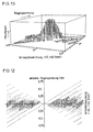
- Fig. 13 shows a corresponding frequency distribution of Control voltage over the angular deviation at 256-QAM above the complex plane with an angular deviation of - 45 ... + 45 Degrees.
- Both of Fig. 13 and Fig. 14 is easy to recognize that only in the central area always right Individual decisions made for the control voltages become. In the border areas is from faulty To make individual decisions.
- EP 0571788 A2 is a carrier and phase control in which only the inner four symbols of the I / Q plane are known with an additional hysteresis as part of a reduced constellation can be used.
- the frequency of these symbols is only a very high small proportion, with equally distributed 256-QAM, for example only about 1.6%.
- EP 0249045 B1 (US 4,811,363, DE 36 19 744 A1) proposes Procedures with a more fundamental approach before, at which a two-step decision is taken. In one first step is decided for a target radius and then in a second step on this decided Target radius then the most probable desired phase point accepted. Thus, a subdivision of the complex level with an orientation to the circle radii, on which the desired symbols are arranged, so that the Limits of the phase control in the radial direction Ring sectors are determined. These decision-making procedures lead to too wrong control voltages, since the received Symbols usually do not lie exactly at the nominal points. For phase constellations of 16-QAM works such Procedure still acceptable.
- the radii boundaries are already so dense together, that in particular with additive noise correct radius decisions only extremely conditionally in one sufficient dimensions are to be obtained.
- 16 shows the distribution of the radii of a 256-QAM received signal.
- the sent radii are with Gaussian Noise folded and applied over the radius R.
- the Decision limits for the desired radii are in the middle between two reference radii, which are represented by dots.
- the proportion of distribution, which is a wrong target radius is assigned is shown with a negative sign. For a single signal, the signal would be below a lower one and above an upper decision boundary a wrong one Radius assigned.
- the illustrated in Fig. 16 Target radii decision is over all constellation points a quadrant integrated with 256-QAM.
- the radii have with up to four desired symbols.
- EP 0 281 652 describes a method which is a early wrong decision for a target radius thereby preventing the first decision from taking place
- Setpoint radius selects a group of set radii that are in one Tolerance range around the radius of the receiving signal before, in a second step, a decision for a phase out of the crowd of all on the selected Sollradien occurring nominal phase values takes place. A further evaluation of the distance between received symbol and selected symbol does not take place.
- the object of the invention is to provide a method for Decide a symbol when receiving one with a Quadrature signal pair to improve coupled signal or a corresponding circuit arrangement for performing a to provide such method.
- This task is solved by the method for deciding a Symbol when receiving one with a quadrature signal pair coupled signal with the features of claim 1 solved.
- a circuit arrangement for performing a Such method is the subject of claim 11.
- the starting point is a procedure for deciding one Symbol when receiving one with a quadrature signal pair coupled signal in which the decision by analysis the distance of at least one reception point to at least a set point of the symbol in complex space.
- the advantageous solution is that the distance in not or not exclusively Cartesian complex Phase space analyzed and depending on the decision is taken.
- the analysis becomes polar Coordinate space performed, including the Cartesian phase space is transformed into a polar coordinate space.
- the decisions or one Preliminary decision instead.
- Decision limits flexible to the respective requirements be set adjusted. For this purpose, variables are set, which depending on the requirement depending dynamically occupied.
- the variable factor can be dynamically linked to the be adapted to each receiving conditions, so that a Automation depending on current reception conditions can be provided.
- the sums of the radial projections and the angle projections of the Distance between receiving point and setpoints is analyzed become. Also, it is advantageously a weighting with Help made a dynamically adjustable factor.
- An auxiliary decision maker (Slicer) can be used.
- a circuit arrangement for performing such Procedure consists essentially of the usual Components of a receiver or decoder. After Conversion of the signal from the I / Q coordinate system into polar Coordinates will be the symbol decision below met. For this purpose, data is drawn in which consists of a Minimization consideration of the different analyzable Phase, radius, I and / or Q coordinates are derived.
- An application of the method or a corresponding Circuit arrangement is particularly suitable for binary or complex digital modulation methods such as QAM.
- modulation methods are of the newer Radio, television and data services via cable, satellite and used terrestrially.
- a demodulator 1 as exemplary circuitry for determining and Decide symbols S, from a digitized signal sd, which is connected to a quadrature signal pair of a Modulation method, z. B. according to a QAM standard, is coupled, from a variety of individual components. These can all or individually also part of a be integrated circuit. In particular, below are described components can be omitted depending on the application or supplemented with other components. Also is the Continuation of signals as real signals, complex Signals or individual complex signal components depending on Application purpose and special circuit arrangement accordingly customizable.
- the demodulator 1 receives at an input from a signal source 2, such as a tuner, an analog signal sa.
- a signal source 2 such as a tuner
- This analog signal sa which is usually present in a band-limited intermediate frequency position, is supplied to an AD converter 3 (AD: analog / digital) for conversion into a digital signal sd.
- AD converter 3 has an input for a clock signal or sampling signal t i .
- the digital signal sd is fed from the AD converter 3 to a bandpass filter 5, which frees the digital signal from DC components and interfering harmonics.
- the output from the bandpass filter 5 signal is a Quadrature converter 6 is supplied, which the digital or digitized signal sd into baseband.
- the Baseband corresponds to the requirements of the demodulator 1 and of the modulation method used. Accordingly, the Quadrature converter in the two Quadrature signal components I, Q of the Cartesian Coordinate system split digitized signal sd out.
- the Quadrature converter in the two Quadrature signal components I, Q of the Cartesian Coordinate system split digitized signal sd out.
- For frequency conversion of the quadrature converter. 6 usually with two staggered by 90 ° straps from a fed to local oscillator 7, its frequency and phase is controlled by a carrier control device 8.
- the quadrature signal components I, Q output from the quadrature converter 6 are supplied to a low-pass filter 9 which serves to eliminate spurious harmonics.
- the low-pass filter 9 and a subsequent symbol scanner 10 form a circuit for sampling rate conversion.
- the symbol scanner 10 has an integrated or upstream scan control device. The control of the symbol scanner 10 via an input to which the sampling signal t i is supplied from a clock controller 21. In the normal operating state, the symbol sampling instants t i are based on the symbol rate 1 / T of the modulation method used or an integral multiple thereof and on the exact phase position of the received symbols.
- the output signal of the scanning device 10 is by means of a low-pass filter 11 having a Nyquist characteristic filtered and a gain control device 12th fed.
- the gain control device 12 is used
- the scope of a predecessor 17 and a Symbolensscheiders 15 calibrated cover.
- the output of the gain controller 12 becomes an equalizer (equalizer) 14 is supplied.
- the equalizer 14 frees the two components of the Quadrature signal pairs I, Q of interfering distortions and represents a preliminary complex symbol S at its exit ready.
- the complex symbol S is given by a subsequent one Coordinate converter, in this case a quadrature converter 20, implemented by the Cartesian into the polar coordinate system, d. H. from a sampled quadrature signal pair I, Q. a polar value pair R, ⁇ is formed.
- circuit arrangements with a Conversion device 6 for converting the digital signal in the complex Cartesian space I, Q and a converter 20 are described for converting to polar coordinates are Also possible circuit arrangements in which already the first converter the digital signal sd into a complex signal with polar coordinates R, ⁇ .
- Symbolentscheiders 15 so-called decided Symbols Se formed in particular both in Cartesian as well as in polar coordinates.
- a Memory unit M with one or more of the Circuit devices is connected.
- the equalizer 14 receives the symbol Se, such as carrier control means 8, a control signal derived from the difference of received target phase ⁇ and decided target phase ⁇ e in a control circuit 22, the gain controller 12 a from the difference of received radius R and decided radius R e in one Amplitude control 13 derived control signal and the sampling device 10 derived from a comparison of the received symbol sequence and the decided symbol sequence in the clock controller 21 sampling signal t i .
- the Control circuits 13 and 22 for carrier control or Amplitude control and other components of the Demodulators 1 are these with a control device in Connection.
- the controller causes a proper operation and controls the individual components and processes based on hardware or software Instructions.
- the control device can also Functions of individual of the components mentioned completely or partially integrated in themselves.
- Q becomes the symbol decision by means of the Symbolentscheiders 15 present in non-Cartesian or not completely in the Cartesian complex coordinate space carried out.
- the decision made by the decision-making body 15 is taken below on the basis of a variety of Diagrams clearly illustrated.
- the goal is the simultaneous consideration of sizes, which depends on the radius R, the angle ⁇ and / or the Cartesian coordinates I and Q are dependent.
- the decision maker 15 is advantageously connected to a memory M, in which et al Comparison data are stored.
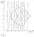
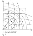
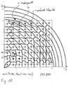
- Fig. 1 there is a Distortion of the decision boxes or Decision radii, if the symbols from the Cartesian I / Q coordinate system in a polar coordinate system with the variables R and ⁇ transformed and rectangular being represented. Shown is the phase constellation the first quadrant of 64-QAM. Shown here is the Phase over the radius, with the vertical lines the Sollradien and the drawn hyperbolas the Represent decision gates of the Cartesian I / Q system. In this distorted form of presentation can now Decisions, d. H. Associations of the received signal S (R, ⁇ ) is performed at a desired signal point Se (R, ⁇ ) become.
- minimization of the Euclidean distance of the received symbols S (R, ⁇ ) and the desired symbols S e (R, ⁇ ) may be performed.
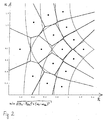
- Examples of such decision gratings for 64-QAM are depicted in FIGS. 2 and 3 for the first quadrant as a polar plane R, ⁇ . 2 shows the polar plane R, ⁇ with a decision grid in which minimization is carried out in accordance with min ( ⁇ (R s -R Se ) 2 + ( ⁇ S - ⁇ Se ) 2 )) ( ⁇ : square root off) ,
- min ⁇ (R s -R Se ) 2 + ( ⁇ S - ⁇ Se ) 2 )
- a minimization decision can be used which uses the sum of the projections on R and ⁇ instead of the Euclidean distance, ie a method according to min (u
- radius component R S and the angle component ⁇ S are present as results from the coordinate converter 20 and the radial component R Se and the angle component ⁇ Se for the desired symbols are in tables in the memory M, such minimum determination can be carried out relatively easily by simple comparisons .
- the decision to the current conditions are adjusted.
- the number of desired symbols to be tested Se can be suitably reduced. For example, first by a decision maker (slicer) 17 in the Cartesian system with a half symbol offset, the square bounded by four symbols can be determined, in which the receiving point is located. Subsequently, only the minimum distance to these four set points is calculated. If the reception point is outside of the setpoint fields, then the four limit setpoints are to be checked in the minimum determination, two of which are closest to the reception point in Cartesian space and two have a higher radius. Such a situation for 256-QAM can be taken from FIG. 10, in which two receiving points S and four respectively corresponding setpoint points S e can be removed.
- the rectangular grid in the I / Q plane in FIG. 10 specifies the four reference points to be checked for the two reception examples, before the minimum determination min (u
- ) is determined in each case. with u 4 done to these four points.
Abstract
Description
Die Erfindung bezieht sich auf ein Verfahren zum Entscheiden
eines Symbols beim Empfang eines mit einem Quadratursignal
gekoppelten Signals gemäß den oberbegrifflichen Merkmalen des
Patentanspruchs 1 bzw. eine Schaltungsanordnung zum
Durchführen eines solchen Verfahrens.The invention relates to a method for deciding
a symbol when receiving one with a quadrature signal
coupled signal according to the preamble features of
Mit Hilfe von kabel- oder funkgestützten Kommunikationssystemen übertragene digitale Signale, die auch als Symbole bezeichnet werden, stellen in codierter Form einen ein- oder mehrstelligen Digitalwert dar. Die Codierung erfolgt für die Übertragung über das Quadratursignalpaar, das einem Zeiger entspricht, der zu bestimmten Zeitpunkten diskrete Positionen im kartesischen Amplituden- und Phasenraum des Quadratursignalpaares einnimmt. Übliche derartige Übertragungsverfahren sind QAM (Quadrature Amplitude Modulation) und PSK (Phase Shift Keying).With the help of cable or radio-based Communication systems also transmit digital signals are called symbols represent in coded form a one or more digit digital value. The encoding takes place for transmission via the quadrature signal pair, the corresponds to a pointer at certain times discrete positions in the Cartesian amplitude and Phase space of the quadrature signal pair occupies. usual Such transmission methods are QAM (Quadrature Amplitude modulation) and PSK (Phase Shift Keying).
In einem üblichen Empfänger zum Empfang digitaler Signale mischt ein komplexer Multiplizierer oder Mischer, der von einem Lokaloszillator angesteuert wird, das empfangene, auf einen Träger modulierte QAM-Signal frequenz- und phasenrichtig in das Basisband der Schaltungsanordnung. Bei einer digitalen Verarbeitung kann dies vor oder nach einer A/D-Umsetzung (A/D: Analog/Digital) erfolgen. Das Signal wird entweder mit dem Symboltakt oder einem Vielfachen davon abgetastet und digitalisiert, oder der Digitalisierungstakt ist gegenüber dem erforderlichen Symboltakt freilaufend. In diesem Fall wird das Symbol letztendlich über eine rein digitale Abtastratenwandlung auf den Symboltakt oder ein Vielfaches davon umgesetzt. Verstärkungsregelungen sorgen dafür, dass der jeweilige Aussteuerbereich ausgenutzt wird und dass die empfangenen Symbole richtig auf die Symbolentscheiderstufe abgebildet werden. Ein adaptiver Entzerrer (Equalizer) vermindert die Intersymbolinterferenz, die in linearen Verzerrungen des Senders, der Übertragungsstrecke oder des Empfänger ihren Ursprung hat.In a conventional receiver for receiving digital signals mixes a complex multiplier or mixer that of a local oscillator is triggered, the received a carrier modulated QAM signal frequency and in-phase into the baseband of the circuitry. at This can be done before or after a digital processing A / D conversion (A / D: analog / digital). The signal is either with the symbol clock or a multiple of it sampled and digitized, or the digitization clock is free running compared to the required symbol clock. In In this case, the symbol eventually becomes a pure digital sample rate conversion to the symbol clock or a Many of them implemented. Provide gain controls that the respective tax area is utilized and that the received symbols are correct on the Symbol decision stage. An adaptive Equalizer reduces intersymbol interference, in linear distortions of the transmitter, the Transmission link or the receiver has its origin.
Bei hochwertigen Demodulatoren für QAM- oder PSK-Signale benötigen die Regelschaltungen für die Frequenz- und Phasenregelung des Lokaloszillators, für die Verstärkungsregelung, für die Rückgewinnung des Symboltaktes und für den adaptiven Entzerrer sowohl die empfangenen Symbole als auch diejenigen Elemente des vorgegebenen Symbolalphabets, die von einer Entscheiderstufe als wahrscheinlichste angesehen werden. Diese Art der Regelung über das entschiedene Symbol wird als "entscheidungsrückgekoppelte" Regelung bezeichnet und setzt für richtige Regelspannungen korrekte Symbolentscheidungen voraus.For high quality demodulators for QAM or PSK signals need the control circuits for the frequency and Phase control of the local oscillator, for the Gain control, for the recovery of the symbol clock and for the adaptive equalizer both the received Symbols as well as those elements of the given Symbol alphabets used by a decision maker as most likely to be viewed. This type of scheme over the decided symbol is called "decision-feedback" scheme designates and sets correct symbol decisions for correct control voltages ahead.
Da bei den digitalen Demodulatoren nach dem Stand der Technik die entscheidungsrückgekoppelten Regelungen miteinander verkoppelt sind, ist das Einrasten schwierig, solange die Regelung für den Lokaloszillator, der das Empfangssignal in das Basisband mischt, frequenz- und phasenmäßig noch nicht stabil ist. Oft gelingt das Einrasten nur, wenn die jeweiligen Frequenzen und Phasen relativ dicht bei ihren Sollwerten liegen.As in the digital demodulators according to the prior art the decision-feedback regulations with each other are locked, the locking is difficult as long as the Control for the local oscillator, which receives the received signal in the baseband does not mix, in terms of frequency and phase is stable. Often the catch succeeds only when the respective frequencies and phases relatively close to their Setpoints are.
Demodulatoren für QAM- oder PSK-Signale benutzen üblicherweise eine Entscheidung, welche in der komplexen I/Q-Symbolebene die empfangenen Symbole nach dem geringsten Abstand zu Sollsymbolen zuordnet. Sind die Sollsymbole auf einem gleichmäßigen Raster angeordnet, entsteht ein Gittermuster für die Entscheidungen.Use demodulators for QAM or PSK signals usually a decision, which in the complex I / Q symbol level the received symbols after the least Assigns distance to desired symbols. Are the nominal symbols on? arranged a uniform grid, creates a Grid pattern for the decisions.
Eine solche Verfahrensweise ist mit Blick auf ein Signal mit additivem Gaußschen Rauschen optimal, jedoch ist im Vorhinein ein exaktes Wissen über die Trägerfrequenz und Trägerphase sowie über den Abtastzeitpunkt erforderlich. Ist die Trägerphase, insbesondere bei höherwertigen Modulationsverfahren, nur wenige Grad von der Sollphase entfernt, werden die Symbole im mittleren und äußeren Radienbereich falsch entschieden. Bei der 256-QAM genügt bereits eine Abweichung von ca. 3 Grad, um falsche Entscheidungen zu treffen. Bei einem Frequenzoffset mit akkumulierendem Phasenfehler ist diese Wirkung noch stärker, da nur jeweils wenige Winkelgrad um eine Abweichung von 0°, bzw. auch 90°, 180°und 270° bei einer Modulobehandlung der Quadranten, eine korrekte Regelspannung erzeugt wird.Such a procedure is with a view to a signal with additive Gaussian noise optimally, but is in advance an exact knowledge of the carrier frequency and carrier phase and beyond the sampling time required. Is the Carrier phase, especially at higher quality Modulation method, just a few degrees from the target phase removed, the icons are in the middle and outer Radius range wrongly decided. With the 256-QAM is enough already a deviation of about 3 degrees to wrong To make decisions. At a frequency offset with accumulating phase error, this effect is even stronger, because only a few angular degrees in each case by a deviation of 0 °, or also 90 °, 180 ° and 270 ° in a modulo treatment of Quadrant, a correct control voltage is generated.
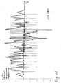
In Fig. 12 sind die Phasenabweichungen zwischen empfangenem und entschiedenem Symbol über einer Winkelabweichung von -45 ... + 45 Grad aufgetragen. Die jeweilige Phasenabweichung dient der Phasenregelung des Lokaloszillators als Regelspannung. Die Verteilung weist eine zentrale Diagonale auf, die vom negativen Quadranten über den Nullpunkt in den positiven Quadranten führt. Bei dem dargestellten Beispiel der gesamten Einzelentscheidungen über die Winkelabweichung in einem Quadranten von 256-QAM ist die Verteilung der einzelnen Regelspannungen so, dass zumindest mit Blick auf das Vorzeichen die richtige mittlere Regelspannung herauskommt. Jedoch ist die momentane Regelspannung oftmals nicht korrekt.In Fig. 12, the phase deviations between received and decided symbol over an angular deviation of -45 ... + 45 degrees applied. The respective phase deviation serves the phase control of the local oscillator as Control voltage. The distribution has a central diagonal on the negative quadrant over the zero point in the positive quadrant leads. In the example shown the entire individual decisions about the angle deviation in a quadrant of 256-QAM is the distribution of individual control voltages so that at least overlooking the sign is the correct mean control voltage comes out. However, the current control voltage is often incorrect.
Fig. 13 stellt eine entsprechende Häufigkeitsverteilung der Regelspannung über die Winkelabweichung bei 256-QAM über der komplexen Ebene bei einer Winkelabweichung von - 45 ... + 45 Grad dar. Die mittlere Regelspannung, d. h. Summe je Winkel über die Winkelabweichung bei 256-QAM, ist Fig. 14 entnehmbar. Sowohl aus Fig. 13 als auch Fig. 14. ist leicht zu erkennen, dass nur im Zentralbereich immer richtige Einzelentscheidungen für die Regelspannungen getroffen werden. In den Randbereichen ist von fehlerhaften Einzelentscheidungen auszugehen. Fig. 13 shows a corresponding frequency distribution of Control voltage over the angular deviation at 256-QAM above the complex plane with an angular deviation of - 45 ... + 45 Degrees. The mean control voltage, d. H. Sum per angle about the angular deviation at 256-QAM, FIG. 14 removable. Both of Fig. 13 and Fig. 14 is easy to recognize that only in the central area always right Individual decisions made for the control voltages become. In the border areas is from faulty To make individual decisions.
Aus EP 0571788 A2 ist eine Träger- und Phasenregelung bekannt, bei welcher nur die inneren vier Symbole der I/Q-Ebene mit einer zusätzlichen Hysterese im Rahmen einer reduzierten Konstellation verwendet werden. Bei höherwertigen Modulationsverfahren mit einer gleichmäßigen Verteilung beträgt die Häufigkeit dieser Symbole jedoch nur einen sehr geringen Anteil, bei gleich verteiltem 256-QAM beispielsweise nur ca. 1,6%.From EP 0571788 A2 is a carrier and phase control in which only the inner four symbols of the I / Q plane are known with an additional hysteresis as part of a reduced constellation can be used. For higher quality Modulation method with a uniform distribution However, the frequency of these symbols is only a very high small proportion, with equally distributed 256-QAM, for example only about 1.6%.
Aus US 5,471,508 ist eine Tracking- bzw. Nachführungsbetriebsart bekannt, mittels der die Regelung zunächst mit einem reduzierten Modulationsalphabet im I/Q-Raum arbeitet, wobei nur große Radien betrachtet werden.From US 5,471,508 is a tracking or Nachführbetriebsart known by means of the control initially with a reduced modulation alphabet in I / Q space works, with only large radii are considered.
Aus DE 199 28 206 A1 ist ein Verfahren bekannt, bei dem die komplexe I/Q-Ebene in kleinere Quadrate aufgeteilt wird, wodurch eine eindeutigere mittlere Regelspannung erhalten werden kann. Dieses Verfahren macht jedoch den Einsatz großer Tabellen erforderlich.From DE 199 28 206 A1 a method is known in which the complex I / Q plane is split into smaller squares, whereby a clearer mean control voltage is obtained can be. However, this method makes the use of large Tables required.
Bei einem Verfahren aus DE 41 00 099 C1 werden nur die Ecken des I/Q-Modulationsalphabets betrachtet, wodurch wiederum viele Symbole verloren gehen. Außerdem wird eine Regelung vorgeschlagen, die für einen effektiven Einsatz zu ungenau ist.In a method of DE 41 00 099 C1 only the corners of the I / Q modulation alphabet, which in turn many symbols are lost. There will also be a regulation suggested that for effective use too inaccurate is.
EP 0249045 B1 (US 4,811,363, DE 36 19 744 A1) schlägt ein Verfahren mit einer grundsätzlicheren Vorgehensweise vor, bei dem eine zweistufige Entscheidung vollzogen wird. In einem ersten Schritt wird für einen Sollradius entschieden und danach in einem zweiten Schritt auf diesem entschiedenen Sollradius dann der wahrscheinlichste Sollphasenpunkt angenommen. Bekannt ist somit auch eine Untergliederung der komplexen Ebene mit einer Orientierung an den Kreisradien, auf welchen die Sollsymbole angeordnet sind, so dass die Grenzen der Phasenregelung in radialer Richtung durch Ringsektoren bestimmt werden. Diese Entscheidungsverfahren führen of zu falschen Regelspannungen, da die empfangenen Symbole üblicherweise nicht exakt auf den Sollpunkten liegen. Für Phasenkonstellationen von 16-QAM funktioniert ein solches Verfahren noch in akzeptablem Maß. Bei Betrachtung einer 64-QAM-Ebene sind jedoch 9 Radien zu berücksichtigen, die teilweise sehr eng benachbart liegen, wie dies aus Fig. 15 ersichtlich ist. Dargestellt sind in der komplexen I/Q-Ebene die Soll-Symbolpositionen von 64-QAM sowie die zugeordneten 9 Radien. In dem positiven Quadranten sind außerdem die Kästchen eines üblichen Gitterentscheidungssystems abgebildet. Ferner dargestellt ist ein kreissegmentförmiger Fangbereich um den zweiten Radius herum, der größtenteils innerhalb eines Kästchens liegt, aber auch in Nachbarkästchen hineinragt.EP 0249045 B1 (US 4,811,363, DE 36 19 744 A1) proposes Procedures with a more fundamental approach before, at which a two-step decision is taken. In one first step is decided for a target radius and then in a second step on this decided Target radius then the most probable desired phase point accepted. Thus, a subdivision of the complex level with an orientation to the circle radii, on which the desired symbols are arranged, so that the Limits of the phase control in the radial direction Ring sectors are determined. These decision-making procedures lead to too wrong control voltages, since the received Symbols usually do not lie exactly at the nominal points. For phase constellations of 16-QAM works such Procedure still acceptable. Considering a 64-QAM level However, there are 9 radii to be taken into account partially very close to each other, as shown in FIG. 15 is apparent. Shown in the complex I / Q level the nominal symbol positions of 64-QAM and the associated 9 Radii. In the positive quadrant are also the Box of a conventional grid decision system displayed. Also shown is a circular segment-shaped Catch area around the second radius, mostly within a box, but also in neighboring boxes protrudes.
Bei 256-QAM liegen die Radiengrenzen bereits so dicht beieinander, dass insbesondere bei additivem Rauschen richtige Radienentscheidungen nur äußerst bedingt in einem ausreichenden Maße zu erhalten sind. Zur Verdeutlichung zeigt Fig. 16 die Verteilung der Radien eines 256-QAM-Empfangssignals. Die gesendeten Radien sind mit Gaußschem Rauschen gefaltet und über dem Radius R aufgetragen. Die Entscheidungsgrenzen für die Sollradien liegen in der Mitte zwischen zwei Sollradien, die durch Punkte dargestellt sind. Der Anteil der Verteilung, welcher einem falschen Sollradius zugeordnet wird, ist mit negativem Vorzeichen dargestellt. Für ein Einzelsignal würde das Signal unterhalb einer unteren und oberhalb einer oberen Entscheidungsgrenze einem falschen Radius zugeordnet. Die in Fig. 16 dargestellte Sollradienentscheidung ist über alle Konstellationspunkte eines Quadranten bei 256-QAM integriert. Die Radien haben dabei bis zu vier Sollsymbole.At 256-QAM, the radii boundaries are already so dense together, that in particular with additive noise correct radius decisions only extremely conditionally in one sufficient dimensions are to be obtained. For clarity shows 16 shows the distribution of the radii of a 256-QAM received signal. The sent radii are with Gaussian Noise folded and applied over the radius R. The Decision limits for the desired radii are in the middle between two reference radii, which are represented by dots. The proportion of distribution, which is a wrong target radius is assigned is shown with a negative sign. For a single signal, the signal would be below a lower one and above an upper decision boundary a wrong one Radius assigned. The illustrated in Fig. 16 Target radii decision is over all constellation points a quadrant integrated with 256-QAM. The radii have with up to four desired symbols.
Für den Fall derartiger Sollradienentscheidungen bei 256-QAM überwiegen erfahrungsgemäß schlechte Radienentscheidungen im mittleren Bereich, in dem die einzelnen Radien im komplexen I/Q-Raum sehr dicht beieinander liegen. In the case of such desired radii decisions at 256-QAM Experience shows that bad radius decisions predominate in the middle area in which the individual radii in the complex I / Q space is very close together.
Ist bei einer Entscheidung ein falscher Sollradius entschieden worden, so kann zwangsläufig auch die nachfolgende Entscheidung für ein Symbol auf diesem Radius nur noch falsch getroffen werden. Somit ist auch die vorstehend aufgeführte Verfahrensweise für höherwertige Modulationsverfahren nicht oder nur allenfalls bedingt einsetzbar.If a decision is a wrong target radius has been decided, so can inevitably subsequent decision for a symbol on this radius only be taken wrong. Thus is also the above procedure for higher quality Modulation method not or only conditionally used.
In EP 0 281 652 wird ein Verfahren beschrieben, das einer frühzeitigen falschen Entscheidung für einen Sollradius dadurch vorbeugt, dass die erste Entscheidung statt eines Sollradius eine Gruppe von Sollradien auswählt, die in einem Toleranzbereich um den Radius des empfangenden Signals liegen, bevor in einem zweiten Schritt eine Entscheidung für eine Phase aus der Menge aller auf den ausgewählten Sollradien vorkommenden Sollphasenwerten stattfindet. Eine weitere Bewertung des Abstandes zwischen empfangenem Symbol und ausgewähltem Symbol findet nicht statt.EP 0 281 652 describes a method which is a early wrong decision for a target radius thereby preventing the first decision from taking place Setpoint radius selects a group of set radii that are in one Tolerance range around the radius of the receiving signal before, in a second step, a decision for a phase out of the crowd of all on the selected Sollradien occurring nominal phase values takes place. A further evaluation of the distance between received symbol and selected symbol does not take place.
Die Aufgabe der Erfindung besteht darin, ein Verfahren zum Entscheiden eines Symbols beim Empfang eines mit einem Quadratursignalpaar gekoppelten Signals zu verbessern bzw. eine entsprechende Schaltungsanordnung zum Durchführen eines solchen Verfahrens bereitzustellen.The object of the invention is to provide a method for Decide a symbol when receiving one with a Quadrature signal pair to improve coupled signal or a corresponding circuit arrangement for performing a to provide such method.
Diese Aufgabe wird durch das Verfahren zum Entscheiden eines
Symbols beim Empfang eines mit einem Quadratursignalpaar
gekoppelten Signals mit den Merkmalen des Patentanspruchs 1
gelöst. Eine Schaltungsanordnung zum Durchführen eines
solchen Verfahrens ist Gegenstand des Patentanspruchs 11.This task is solved by the method for deciding a
Symbol when receiving one with a quadrature signal pair
coupled signal with the features of
Ausgegangen wird von einem Verfahren zum Entscheiden eines Symbols beim Empfang eines mit einem Quadratursignalpaar gekoppelten Signals, bei dem die Entscheidung durch Analyse des Abstands zumindest eines Empfangspunkts zu zumindest einem Sollpunkt des Symbols im komplexen Raum getroffen wird. Die vorteilhafte Lösung besteht darin, dass der Abstand im nicht oder nicht ausschließlich kartesischen komplexen Phasenraum analysiert und davon abhängig die Entscheidung getroffen wird.The starting point is a procedure for deciding one Symbol when receiving one with a quadrature signal pair coupled signal in which the decision by analysis the distance of at least one reception point to at least a set point of the symbol in complex space. The advantageous solution is that the distance in not or not exclusively Cartesian complex Phase space analyzed and depending on the decision is taken.
Statt einer reinen Kästchenentscheidung für ein bestimmtes Sollsymbol oder einer reinen Radienentscheidung für einen bestimmten Sollradius mit nachfolgender Bestimmung der Sollphase liegt somit eine kombinierte Verfahrensweise für die Entscheidung vor, welche gleichzeitig radiale und phasenabhängige Aspekte berücksichtigt.Instead of a pure box decision for a particular Target symbol or a pure radius decision for one certain setpoint radius with subsequent determination of Target phase is thus a combined procedure for the decision, which simultaneously radial and phase-dependent aspects considered.
Bestimmt werden bei dieser Verfahrensweise somit nicht nacheinander in einem ersten Schritt für ein empfangenes Symbol besonders geeignete Radien, um in einem nachfolgenden Schritt dann auf diesem Radien einen geeigneten Winkel zu suchen, sondern anstelle dessen werden nunmehr Radius und Winkel gleichzeitig in einer einzigen Entscheidung betrachtet, indem der Abstand zwischen einem Empfangspunkt und einem Sollpunkt betrachtet wird.Are determined in this procedure thus not successively in a first step for a received Symbol particularly suitable radii to in a subsequent Then step on this radius to a suitable angle search, but now instead of radius and Angles simultaneously in a single decision considered by the distance between a receiving point and a set point.
Vorteilhafte Ausgestaltungen sind Gegenstand abhängiger Ansprüche.Advantageous embodiments are the subject of dependent Claims.
Vorteilhafterweise wird die Analyse im polaren Koordinatenraum durchgeführt, wozu der kartesische Phasenraum in einen polaren Koordinatenraum transformiert wird. In diesem finden dann die Entscheidungen oder eine Vorentscheidung statt. Vorteilhafterweise können bei einer kombinierten Betrachtung von Größen, die von der radialen Komponente und/oder der Phasenkomponente abhängig sind, Entscheidungsgrenzen flexibel dem jeweiligen Erfordernissen angepasst gesetzt werden. Dazu werden Variablen festgelegt, welche je nach Erfordernis abhängig dynamisch belegt werden. Advantageously, the analysis becomes polar Coordinate space performed, including the Cartesian phase space is transformed into a polar coordinate space. In this will then find the decisions or one Preliminary decision instead. Advantageously, in a combined consideration of sizes, that of the radial Component and / or the phase component are dependent, Decision limits flexible to the respective requirements be set adjusted. For this purpose, variables are set, which depending on the requirement depending dynamically occupied.
Die sich dadurch ergebende größere Toleranz gegenüber Phasenfehlern ist insbesondere bei einer Decision-Feedback-Regelung im Hunting-Modus wichtig, in dem Empfangsfrequenz und Empfangsphase noch nicht eingerastet sind.The resulting greater tolerance to Phase errors are especially in decision feedback control important in hunting mode, in the receiving frequency and reception phase are not locked yet.
Eine Kombination von polaren und kartesischen Entscheidungen bietet insbesondere bei Signalen mit additivem Rauschen eine gute Leistungsfähigkeit.A combination of polar and Cartesian decisions offers one especially for signals with additive noise good performance.
Prinzipiell können auch andere Transformationsverfahren benutzt werden, je nachdem welches Koordinatensystem sich für die jeweiligen Zielsetzungen als geeignet erweist, um optimale Entscheidungen zu erhalten.In principle, other transformation methods can also be used be used, depending on which coordinate system is for the respective objectives proves to be appropriate to get optimal decisions.
Als radien- und phasenabhängiges Kriterium für die Entscheidung dient insbesondere die Betrachtung und Analyse eines euklidischen Abstands des Empfangspunkts zu den möglichen Sollpunkten. Dabei wird vorteilhafterweise ein Faktor eingeführt, welcher die Wichtung von Radius- und Phasen-/Winkelfehler zueinander festlegt, um je nach Signalzustand eine optimale Wichtung zu erhalten. Vorteilhafterweise kann der variable Faktor dynamisch an die jeweiligen Empfangsbedingungen angepasst werden, so dass eine Automatisierung je nach momentanen Empfangsbedingungen vorgesehen werden kann.As radii and phase dependent criterion for the Decisions serve in particular the consideration and analysis an Euclidean distance of the reception point to the possible setpoints. It is advantageously a Factor introduced, which the weighting of radius and Phase / angle error determines each other, depending on Signal state to obtain optimal weighting. Advantageously, the variable factor can be dynamically linked to the be adapted to each receiving conditions, so that a Automation depending on current reception conditions can be provided.
Zusätzlich oder alternativ können auch die Summen der radialen Projektionen und der Winkel-Projektionen des Abstands zwischen Empfangspunkt und Sollpunkten analysiert werden. Auch dabei wird vorteilhafterweise eine Wichtung mit Hilfe eines dynamisch anpassbaren Faktors vorgenommen.Additionally or alternatively, the sums of the radial projections and the angle projections of the Distance between receiving point and setpoints is analyzed become. Also, it is advantageously a weighting with Help made a dynamically adjustable factor.
Besonders vorteilhaft ist eine Kombination von derartigen Analysen und Bestimmungen aus verschiedenen Koordinatensystemen, beispielsweise die Analyse einerseits im polaren Koordinatensystem und andererseits im kartesischen Koordinatensystem, wobei eine gemeinsame Bewertung vorgenommen wird. Auch dabei ist wieder ein Wichtungsfaktor vorteilhaft einsetzbar, um eine dynamische Anpassung an die Empfangsbedingungen zu ermöglichen.Particularly advantageous is a combination of such Analyzes and determinations from different Coordinate systems, for example, the analysis on the one hand in polar coordinate system and on the other hand in Cartesian Coordinate system, with a common rating is made. Again, this is a weighting factor can be used advantageously to a dynamic adaptation to the To enable reception conditions.
Um relevante zu prüfende Sollphasenpunkte zu identifizieren, kann ein Hilfsentscheider (Slicer) verwendet werden.To identify relevant target phase points to be tested, An auxiliary decision maker (Slicer) can be used.
Eine Schaltungsanordnung zum Durchführen eines solchen Verfahrens besteht aus im Wesentlichen den üblichen Bauelementen eines Empfängers bzw. Dekoders. Nach der Umsetzung des Signals aus dem I/Q-Koordinatensystem in polare Koordinaten wird nachfolgend die Symbolentscheidung getroffen. Dazu werden Daten hinzugezogen, die aus einer Minimalisierungsbetrachtung der verschiedenen analysierbaren Parameter Phase, Radius, I- und/oder Q-Koordinate stammen.A circuit arrangement for performing such Procedure consists essentially of the usual Components of a receiver or decoder. After Conversion of the signal from the I / Q coordinate system into polar Coordinates will be the symbol decision below met. For this purpose, data is drawn in which consists of a Minimization consideration of the different analyzable Phase, radius, I and / or Q coordinates are derived.
Eine Anwendung des Verfahrens bzw. einer entsprechenden Schaltungsanordnung bietet sich insbesondere bei binären oder komplexen digitalen Modulationsverfahren wie QAM an. Derartige Modulationsverfahren werden von den neueren Rundfunk-, Fernseh- und Datendiensten über Kabel, Satellit und terrestrisch benutzt.An application of the method or a corresponding Circuit arrangement is particularly suitable for binary or complex digital modulation methods such as QAM. Such modulation methods are of the newer Radio, television and data services via cable, satellite and used terrestrially.
Ein Ausführungsbeispiel der Erfindung und verschiedene Ausführungsformen dazu werden nachstehend anhand der Zeichnung näher erläutert. Es zeigen:
- Fig. 1
- eine Phasenkonstellation des ersten Quadranten von 64-QAM, bei dem die Phase über dem Radius dargestellt ist;
- Fig. 2, 3
- Phasenkonstellationen in der polaren Koordinatenebene mit verschieden gewählten Entscheidungsparametern;
- Fig. 4, 5
- Abbildungen der I/Q-Ebene mit Entscheidungsgittern mit jeweils verschiedenen von Radien und Phasen abhängigen Minimierungsbedingungen;
- Fig. 6, 7
- Diagramme in der polaren bzw. kartesischen Ebene, die statt der Minimierung des euklidischen Abstandes in einem entsprechend gewichteten R-α-Koordinatensystem die Summe entsprechend gewichteter Radius- und Winkelprojektionen minimiert;
- Fig. 8
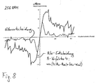
- einen Vergleich mittlerer Regelspannungen bei einer Entscheidung im polaren Koordinatenraum gegenüber einer herkömmlichen Entscheidungsweise;
- Fig. 9,
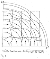
- ein Diagramme im kartesischen Koordinatensystem mit kombinierten polaren und kartesischen Entscheidungskriterien;
- Fig. 10,
- ein Diagramm mit Entscheidungskriterien wie in Fig.
6
und 7, bei denen die Menge der bei der Entscheidung zu berücksichtigenden Sollpunkte beschränkt wurde; - Fig. 11
- ein Schaltungsdiagramm für einen Dekoder zum Entscheiden eines Symbols;
- Fig. 12 - 14
- Regelspannungen über der Winkelabweichung gemäß dem Stand der Technik in verschiedenen Darstellungsarten;
- Fig. 15
- eine Darstellung der komplexen I/Q-Ebene mit Symbolpositionen sowie Kästchen und Radien zur Symbolentscheidung gemäß dem Stand der Technik und
- Fig. 16
- das Ergebnis einer entsprechenden Sollradienentscheidung über alle Konstellationspunkte eines Quadranten bei einer 256-QAM bei überlagertem Gaußschem Rauschen.
- Fig. 1
- a phase constellation of the first quadrant of 64-QAM, in which the phase is shown above the radius;
- Fig. 2, 3rd
- Phase constellations in the polar coordinate plane with different chosen decision parameters;
- Fig. 4, 5
- Images of the I / Q plane with decision gratings, each with different radius and phase dependent minimization conditions;
- Fig. 6, 7
- Polar and Cartesian plane diagrams that minimize the sum of weighted radius and angle projections rather than minimizing the Euclidean distance in a correspondingly weighted R-α coordinate system;
- Fig. 8
- a comparison of average control voltages in a decision in polar coordinate space compared to a conventional decision mode;
- Fig. 9,
- a diagram in the Cartesian coordinate system with combined polar and Cartesian decision criteria;
- Fig. 10,
- a diagram with decision criteria as in Figures 6 and 7, in which the amount of the set points to be taken into account in the decision was limited;
- Fig. 11
- a circuit diagram for a decoder for deciding a symbol;
- Fig. 12 - 14
- Control voltages over the angle deviation according to the prior art in various types of representation;
- Fig. 15
- a representation of the complex I / Q plane with symbol positions and boxes and radii for symbol decision according to the prior art and
- Fig. 16
- the result of a corresponding command radius decision across all constellation points of a quadrant in a 256-QAM with superimposed Gaussian noise.
Wie dies aus Fig. 11 ersichtlich ist, besteht ein Demodulator
1 als beispielhafte Schaltungsanordnung zum Bestimmen und
Entscheiden von Symbolen S, aus einem digitalisierten Signal
sd, welches an ein Quadratursignalpaar eines
Modulationsverfahrens, z. B. gemäß einem QAM-Standard,
gekoppelt ist, aus einer Vielzahl von Einzelkomponenten.
Diese können alle oder einzeln auch Bestandteil einer
integrierten Schaltung sein. Insbesondere sind nachfolgend
beschriebene Komponenten je nach Anwendungszweck weglassbar
oder um weitere Komponenten ergänzbar. Auch ist die
Weiterführung von Signalen als reelle Signale, komplexe
Signale oder einzelne komplexe Signalkomponenten je nach
Anwendungszweck und spezieller Schaltungsanordnung
entsprechend anpassbar.As can be seen from Fig. 11, there is a
Bei der dargestellten Ausführungsform empfängt der
Demodulator 1 an einem Eingang von einer Signalquelle 2,
beispielsweise einem Tuner, ein analoges Signal sa. Dieses
analoge Signal sa, welches üblicherweise in einer
bandbegrenzten Zwischenfrequenzlage vorliegt, wird einem AD-Umsetzer
3 (AD: Analog/Digital) zum Umsetzen in ein digitales
Signal sd zugeführt. Für den Fall, dass die weiteren
Schaltungskomponenten keine Symbol-Abtasteinrichtung
aufweisen sollten, weist der AD-Umsetzer 3 einen Eingang für
ein Taktsignal bzw. Abtastsignal ti auf. Das digitale Signal
sd wird vom AD-Umsetzer 3 zu einem Bandpass-Filter 5 geführt,
welcher das digitale Signal von Gleichanteilen und störenden
Oberwellen befreit.In the illustrated embodiment, the
Das vom Bandpass-Filter 5 ausgegebene Signal wird einem
Quadraturumsetzer 6 zugeführt, welcher das digitale bzw.
digitalisierte Signal sd in das Basisband umsetzt. Das
Basisband entspricht den Anforderungen des Demodulators 1 und
des verwendeten Modulationsverfahrens. Entsprechend gibt der
Quadraturumsetzer das in die beiden
Quadratursignalkomponenten I, Q des kartesischen
Koordinatensystems aufgesplittete digitalisierte Signal sd
aus. Zur Frequenzumsetzung wird der Quadraturumsetzer 6
üblicherweise mit zwei um 90° versetzten Trägern aus einem
lokalen Oszillator 7 gespeist, dessen Frequenz und Phase
durch eine Trägerregeleinrichtung 8 gesteuert wird.The output from the
Die Quadratursignalkomponenten I, Q, die von dem
Quadraturumsetzer 6 ausgegeben werden, werden einem Tiefpass-Filter
9 zugeführt, welcher zur Beseitigung störender
Oberwellen dient. Der Tiefpassfilter 9 und eine diesem
nachfolgende Symbol-Abtasteinrichtung 10 bilden eine
Schaltung zur Abtastratenwandlung aus. Zweckmäßigerweise
weist die Symbol-Abtasteinrichtung 10 eine integrierte oder
vorgeschaltete Abtastregelungseinrichtung auf. Die Steuerung
der Symbol-Abtasteinrichtung 10 erfolgt über einen Eingang,
dem das Abtastsignal ti von einer Taktsteuereinrichtung 21
zugeführt wird. Die Symbol-Abtastzeitpunkte ti orientieren
sich im normalen Betriebszustand an der Symbolrate 1/T des
verwendeten Modulationsverfahrens oder einem ganzzahligen
Vielfachen davon und an der genauen Phasenlage der
empfangenen Symbole.The quadrature signal components I, Q output from the
Das Ausgangssignal der Abtasteinrichtung 10 wird mittels
eines Tiefpass-Filters 11 mit einer Nyquist-Charakteristik
gefiltert und einer Verstärkungsregelungseinrichtung 12
zugeführt. Die Verstärkungsregelungseinrichtung 12 dient
dazu, den Aussteuerbereich eines Vorentscheiders 17 und eines
Symbolentscheiders 15 kalibriert abzudecken.The output signal of the
Das Ausgangssignal der Verstärkungsregeleinrichtung 12 wird
einem Entzerrer (Equalizer) 14 zugeführt.The output of the
Alternativ kann auch eine sich selbst regelnde
Verstärkungsregelungseinrichtung eingesetzt werden, wobei
dann insbesondere die eigenständige
Amplitudensteuereinrichtung 13 entfallen kann.Alternatively, a self-regulating
Reinforcement control device are used, wherein
then in particular the independent ones
Der Entzerrer 14 befreit die beiden Komponenten des
Quadratursignalpaars I, Q von störenden Verzerrungen und
stellt ein vorläufiges komplexes Symbol S an seinem Ausgang
bereit. Das komplexe Symbol S wird von einem nachfolgenden
Koordinatenumsetzer, vorliegend einem Quadraturumsetzer 20,
vom kartesischen in das polare Koordinatensystem umgesetzt,
d. h. aus einem abgetasteten Quadratursignalpaar I, Q wird
ein polares Wertepaar R, α gebildet.The
Mit den Polarkoordinaten werden somit eine Radiuskomponente R
und eine Winkelkomponente α gemäß I = R·cos(α) und Q =
R·sin(α) und gemäß den Beziehungen
Bei der digitalen Signalverarbeitung wird für die Koordinatentransformation häufig das sogenannte Cordic-Verfahren verwendet, bei dem für die Umwandlung nur Additionen und Zweier-Multiplikationen, welche bei Binärzahlen durch einfache Stellenverschiebungen zu realisieren sind, verwendet werden. Alternativ sind auch andere Näherungsverfahren oder die Verwendung von Tabellen möglich. Die inverse Umsetzung, also die Umsetzung von polaren Signalkomponenten R und α, in ihre Quadraturkomponenten I bzw. Q kann ebenfalls mit einem Cordic-Umsetzer, einer Tabelle oder einem Näherungsverfahren erfolgen.In digital signal processing is for the Coordinate transformation often the so-called Cordic method used in the case of conversion only Additions and twofold multiplications, which at Binary numbers by simple shift of positions too are to be used. Alternatively, too other approximation methods or the use of tables possible. The inverse conversion, ie the implementation of polar signal components R and α, in their Quadrature components I and Q can also be combined with a Cordic translator, a table or an approximation method respectively.
Während eine Schaltungsanordnung mit einer
Umsetzungseinrichtung 6 zum Umsetzen des digitalen Signals in
den komplexen kartesischen Raum I, Q und einem Umsetzer 20
zum Umsetzen in polare Koordinaten beschrieben sind, sind
auch Schaltungsanordnungen möglich, bei denen bereits der
erste Umsetzer das digitale Signal sd in ein komplexes Signal
mit polaren Koordinaten R, α umsetzt.While a circuit arrangement with a
Aus derart bereitgestellten vorläufigen Symbolen werden
mittels des Symbolentscheiders 15 sogenannte entschiedene
Symbole Se gebildet, die insbesondere sowohl in kartesischen
als auch in polaren Koordinaten vorliegen können. Zum
Abspeichern der Werte dient zweckmäßigerweise eine
Speichereinheit M, die mit einer oder mehreren der
Schaltungseinrichtungen verbunden ist.Become from such provided preliminary symbols
by means of the
Diese Symbole S, Se und/oder deren Radialkomponente Re oder
αe werden dann weiteren digitalen
Signalverarbeitungseinrichtungen 16 und vorzugsweise auch den
entscheidungsrückgekoppelten Regelkreisen bzw. Komponenten im
Demodulator 1 direkt oder indirekt zugeführt. Insbesondere
erhält der Entzerrer 14 das Symbol Se, wie
Trägerregeleinrichtung 8 ein aus der Differenz von
empfangener Sollphase α und entschiedener Sollphase αe in
einer Steuerschaltung 22 abgeleitetes Regelsignal, die
Verstärkungsregeleinrichtung 12 ein aus der Differenz von
empfangenem Radius R und entschiedenem Radius Re in einer
Amplitudensteuereinrichtung 13 abgeleitetes Regelsignal und
die Abtasteinrichtung 10 ein aus einem Vergleich der
empfangenen Symbolfolge und der entschiedenen Symbolfolge in
der Taktsteuereinrichtung 21 abgeleitetes Abtastsignal ti.These symbols S, Se and / or their radial component R e or α e are then supplied directly or indirectly to further digital
Zur Steuerung der Taktsteuereinrichtung 21, der
Steuerschaltungen 13 und 22 zur Trägersteuerung bzw.
Amplitudensteuerung und weiterer der Komponenten des
Demodulators 1 stehen diese mit einer Steuereinrichtung in
Verbindung. Die Steuereinrichtung bewirkt einen
ordnungsgemäßen Ablauf und steuert die einzelnen Komponenten
und Abläufe entsprechend Hart- oder Software gestützten
Anweisungen. Vorzugsweise kann die Steuereinrichtung auch
Funktionen einzelner der genannten Komponenten ganz oder
teilweise in sich integriert aufweisen.For controlling the
Im Gegensatz zur üblichen Symbolbestimmung mit Hilfe des
Symbolentscheiders 15 im kartesischen komplexen
Koordinatenraum I, Q wird die Symbolentscheidung mittels des
Symbolentscheiders 15 vorliegend im nicht kartesischen oder
nicht vollständig im kartesischen komplexen Koordinatenraum
durchgeführt.In contrast to the usual symbol determination with the help of the
Die Entscheidung, welche durch die Entscheidungseinrichtung
15 getroffen wird, wird nachfolgend anhand einer Vielzahl von
Diagrammen anschaulich erläutert. Ziel ist dabei die
gleichzeitige Betrachtung von Größen, welche von dem Radius
R, dem Winkel α und/oder den kartesischen Koordinaten I und Q
abhängig sind. Die Entscheidungseinrichtung 15 ist
vorteilhafterweise mit einem Speicher M verbunden, in dem
u.a. Vergleichsdaten hinterlegt sind.The decision made by the decision-making
Wie dies aus Fig. 1 ersichtlich ist, ergibt sich eine Verzerrung der Entscheidungskästchen bzw. Entscheidungsradien, wenn die Symbole aus dem kartesischen I/Q-Koordinatensystem in ein polares Koordinatensystem mit den Variablen R und α transformiert und rechtwinkelig dargestellt werden. Abgebildet ist die Phasenkonstellation des ersten Quadranten von 64-QAM. Dargestellt ist dabei die Phase über dem Radius, wobei die senkrechten Linien die Sollradien und die eingezeichneten Hyperbeln das Entscheidungsgitter des kartesischen I/Q-Systems darstellen. In dieser verzerrten Darstellungsform können nun Entscheidungen, d. h. Zuordnungen des empfangenen Signals S(R, α) zu einem Sollsignalpunkt Se(R, α) durchgeführt werden.As can be seen from Fig. 1, there is a Distortion of the decision boxes or Decision radii, if the symbols from the Cartesian I / Q coordinate system in a polar coordinate system with the variables R and α transformed and rectangular being represented. Shown is the phase constellation the first quadrant of 64-QAM. Shown here is the Phase over the radius, with the vertical lines the Sollradien and the drawn hyperbolas the Represent decision gates of the Cartesian I / Q system. In this distorted form of presentation can now Decisions, d. H. Associations of the received signal S (R, α) is performed at a desired signal point Se (R, α) become.
Wegen des grundsätzlich unterschiedlichen Charakters der beiden variablen Radius R und Phase α ist dabei eine zusätzliche Bearbeitung zweckmäßig. Because of the fundamentally different nature of the two variable radius R and phase α is a additional processing appropriate.
Erstens sollte dabei betrachtet werden, in welchem Verhältnis die beiden Koordinaten R, α stehen, wobei in der Fig. 1 eine nur arbiträr aufgetragene Achseneinteilung skizziert ist. Für die nachfolgenden Rechnungen ist Radius so kalibriert, dass die Längen beider Seiten des Kastens, der alle Phasenpunkte umschließt jeweils 1 ist, wodurch der Eckpunkt auf einen Wert von √2 fällt, und der Winkelumfang eines Quadranten π/2 ist.First, it should be considered in what proportion the two coordinates R, α are, wherein in Fig. 1 a only arbitrarily plotted axis classification is outlined. For the subsequent calculations, radius is calibrated so that the lengths of both sides of the box, all the phase points encloses 1 each, causing the vertex to a value falls from √2, and the angular extent of a quadrant π / 2 is.
Zweitens sollte betrachtet werden, wie die Abstandsfunktion in der polaren Koordinatenebene R, α zu bestimmen ist.Second, consider how the distance function in the polar coordinate plane R, α is to be determined.
Aus Fig. 1 ist bereits zu erkennen, dass einigen Symbolpositionen jeweils im Vergleich zu den anderen Bestimmungssystemen relativ große Fangbereiche um die Sollpositionen herum zugeordnet werden können.From Fig. 1 it can already be seen that some Symbol positions in each case in comparison to the others Determination systems relatively large catch areas around the Target positions can be assigned around.
Um eine weitere Optimierung des Betrachtungssystems vorzunehmen, kann eine Minimierung des euklidischen Abstands der empfangenen Symbole S(R, α) und der Sollsymbole Se(R, α) durchgeführt werden. Beispiele für solche Entscheidungsgitter für 64-QAM sind in der Fig. 2 und 3 für den ersten Quadranten eine polare Ebene R, α abgebildet ist. Dabei zeigt Fig. 2 die polare Ebene R, α mit einem Entscheidungsgitter, bei dem die Minimierung gemäß min (√ (RS - RSe)2 + (αS - αSe)2)) (√ : Quadratwurzel aus) durchgeführt wird. Für den Bereich mit geringen Radien ergeben sich relativ große Zellen, während die Zellengrößen für größere Radien abnehmen.In order to further optimize the viewing system, minimization of the Euclidean distance of the received symbols S (R, α) and the desired symbols S e (R, α) may be performed. Examples of such decision gratings for 64-QAM are depicted in FIGS. 2 and 3 for the first quadrant as a polar plane R, α. 2 shows the polar plane R, α with a decision grid in which minimization is carried out in accordance with min (√ (R s -R Se ) 2 + (α S -α Se ) 2 )) (√: square root off) , For the low radius region, relatively large cells result while cell sizes decrease for larger radii.
Die Einführung von Vorfaktoren u, w erlaubt es, die Radiusund Winkelfelder unterschiedlich stark zu wichten gemäß min((√2u·(RS - RSe)2 + w(αS - αSe)2)) .Da es nur auf die Bestimmung des Minimums und nicht auf absolute Werte ankommt, genügt ein entsprechend gewählter Faktor u. Für die weiteren Betrachtungen wird daher w = 1 gewählt. The introduction of prefactors u, w allows the radius and angular fields to be weighted differently according to min ((√2u · (R S - R Se ) 2 + w (α S - α Se ) 2 )) Determination of the minimum and not arrive at absolute values, satisfies a correspondingly selected factor u. For the further considerations, therefore, w = 1 is chosen.
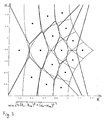
Fig. 3 zeigt die Situation bei einer Betrachtung der Minimierung des euklidischen Abstandes unter Verwendung eines Radius-Faktors u mit u = 4, der so den radialen Anteil gegenüber dem Winkelanteil gemäß der Formel min(SQRT(u·(RS - RSe)2 + (αS - αSe)2)) stärker gewichtet. Dies führt zu einer Dehnung der Entscheidungsbereiche in Richtung der Winkelgröße α.3 shows the situation when considering the minimization of the Euclidean distance using a radius factor u with u = 4, which thus determines the radial component in relation to the angular component according to the formula min (SQRT (u * (R s -R Se ) 2 + (α S - α Se ) 2 )) are weighted more heavily. This leads to an expansion of the decision areas in the direction of the angle size α.
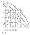
Eine Rücktransformation des Entscheidungsgitters des ersten Quadranten mit dem Faktor u = 4 aus Fig. 3 in die kartesische Ebene I/Q ist in Fig. 4 dargestellt. Obwohl im mittleren Radiusbereich die Entscheidungsfelder schon relativ schmal werden, schneiden die Grenzen im Außenbereich den äußersten Radius, was unerwünscht ist. Bei der Bestimmung des euklidischen Abstandes ohne einen Vorfaktor bzw. mit u = 1 gemäß Fig. 2 fächern somit die Außenbereiche weiter auf, wie dies aus Fig. 5 ersichtlich ist.An inverse transformation of the decision grid of the first Quadrants with the factor u = 4 of Fig. 3 in the Cartesian Level I / Q is shown in FIG. Although in the middle Radius range the decision fields already relatively narrow outside borders cut to the last Radius, which is undesirable. In determining the Euclidean distance without a prefactor or with u = 1 As shown in FIG. 2, the outdoor areas fan further, such as this is apparent from Fig. 5.
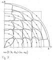
Alternativ kann beispielsweise auch eine Minimierungsentscheidung verwendet werden, die anstelle des euklidischen Abstandes die Summe der Projektionen auf R und α verwendet, d. h. eine Verfahrensweise gemäß min(u|RS-RSw| +|αS-αSe|)·Alternatively, for example, a minimization decision can be used which uses the sum of the projections on R and α instead of the Euclidean distance, ie a method according to min (u | R s -R Sw | + | α S -α Se |).
Wie dies aus Fig. 6 ersichtlich ist, welche die polare Koordinatenebene R, α mit einem Entscheidungsgitter mit dem Radius-Faktor u = 2 für die radiale Komponente zeigt, ist die Zelleinteilung bzw. die Einteilung der Fangbereiche vorteilhafter, als dies bei der Betrachtung der reinen euklidischen Abstände selbst mit der höheren Radius-Gewichtung von u = 4 war.As can be seen from Fig. 6, which is the polar Coordinate plane R, α with a decision grid with the Radius factor u = 2 for the radial component shows is the Cell division or division of catch areas more advantageous than this when considering the pure Euclidean distances even with the higher radius weighting from u = 4 was.
Fig. 7 zeigt die Rücktransformation des Entscheidungsgitters
aus Fig. 6 in der entsprechenden I/Q-Koordinatenebene. Bei
dieser Minimierung werden im Außenbereich die Radiengrenzen
richtig getroffen, während im zentralen Bereich eine
modifizierte Gitterentscheidungs-Verfahrensweise vorliegt.
Wie aus der Darstellung der mittleren Regelspannung bei 256-QAM
gemäß Fig. 8 ersichtlich ist, ist die Funktion der
mittleren Phasenregelspannung wesentlich besser als bei einer
reinen Gitterentscheidung gemäß dem Stand der Technik.
Verwendet wurde eine Minimierungsfunktion mit der Summe der
Projektionen und dem Radius-Vorfaktor u = 4, analog der Fig.
6, 7.Fig. 7 shows the inverse transformation of the decision grid
from Fig. 6 in the corresponding I / Q coordinate plane. at
This minimization will be outside the radius boundaries
hit right, while in the central area one
modified lattice decision procedure is present.
As shown in the representation of the average control voltage at 256-
Da die Radiuskomponente RS und die Winkelkomponente αS als
Ergebnisse aus dem Koordinatenumsetzer 20 vorliegen und die
radiale Komponente RSe und die Winkelkomponente αSe für die
Sollsymbole in Tabellen in dem Speicher M vorliegen, lässt
sich eine solche Minimumbestimmung durch einfache Vergleiche
relativ leicht ausführen. Während des Betriebes kann durch
eine einfache Änderung des Vorfaktors, insbesondere Radius-Vorfaktors
u, die Entscheidung an die momentanen
Gegebenheiten, beispielsweise hohen Phasenjitter oder aber
starkes Rauschen, angepasst werden.Since the radius component R S and the angle component α S are present as results from the coordinate
Aus Fig. 7 ist eine Krümmung der Entscheidungsgrenzen für die
Fangbereiche beim innersten Symbol auffallend. Diese Krümmung
entsteht aus der großen Winkelabweichung, welche an den
Kanten des Quadranten die Entscheidung bestimmt. Durch das
Hinzufügen eines Terms in der Minimumentscheidung, welcher
die Abstände in der kartesischen komplexen I/Q-Ebene
repräsentiert, kann dieser Effekt jedoch vermindert werden.
Durch die Kombination beider Minimierungsverfahren können
alle Entscheidungsfelder bzw. Fangfelder um die
Sollphasenpunkte der Sollsymbole Se herum aufgeweitet werden,
wie dies aus Fig. 9 ersichtlich ist. Fig. 9 zeigt die
kartesische I/Q-Ebene mit einem Entscheidungsgitter gemäß
Um den Aufwand der Minimum-Berechnung zu verkleinern, kann die Anzahl der zu prüfenden Sollsymbole Se geeignet verkleinert werden. Zum Beispiel kann zunächst durch einen Entscheider bzw. Vorentscheider (Slicer) 17 im kartesischen System mit einem halben Symbolversatz das durch vier Symbole begrenzte Quadrat bestimmt werden, in welchem der Empfangspunkt liegt. Anschließend wird nur die Minimaldistanz zu diesen vier Sollpunkten berechnet. Liegt der Empfangspunkt außerhalb der Sollfelder, so sind bei der Minimumbestimmung die vier Randsollpunkte zu prüfen, von denen zwei dem Empfangspunkt im kartesischen Raum am nächsten liegen und zwei einen höheren Radius haben. Eine solche Situation für 256-QAM ist Fig. 10 entnehmbar, in der zwei Empfangspunkte S und jeweils vier entsprechend zugeordnete Sollpunkte Se entnehmbar sind. Das rechtwinklige Gitter in der I/Q-Ebene in Fig. 10 legt die je vier zu prüfenden Sollpunkte für die zwei Empfangsbeispiele fest, bevor jeweils die Minimumbestimmung min(u|RS-RSe|+|αS-αSe|) mit u = 4 zu diesen vier Punkten erfolgt.In order to reduce the effort of the minimum calculation, the number of desired symbols to be tested Se can be suitably reduced. For example, first by a decision maker (slicer) 17 in the Cartesian system with a half symbol offset, the square bounded by four symbols can be determined, in which the receiving point is located. Subsequently, only the minimum distance to these four set points is calculated. If the reception point is outside of the setpoint fields, then the four limit setpoints are to be checked in the minimum determination, two of which are closest to the reception point in Cartesian space and two have a higher radius. Such a situation for 256-QAM can be taken from FIG. 10, in which two receiving points S and four respectively corresponding setpoint points S e can be removed. The rectangular grid in the I / Q plane in FIG. 10 specifies the four reference points to be checked for the two reception examples, before the minimum determination min (u | R s -R Se | + | α S -α Se |) is determined in each case. with u = 4 done to these four points.
Claims (11)
Applications Claiming Priority (2)
| Application Number | Priority Date | Filing Date | Title |
|---|---|---|---|
| DE10344756A DE10344756A1 (en) | 2003-09-25 | 2003-09-25 | Method and circuit arrangement for deciding a symbol in the complex phase space of a quadrature modulation method |
| DE10344756 | 2003-09-25 |
Publications (2)
| Publication Number | Publication Date |
|---|---|
| EP1523144A2 true EP1523144A2 (en) | 2005-04-13 |
| EP1523144A3 EP1523144A3 (en) | 2006-08-16 |
Family
ID=34306094
Family Applications (1)
| Application Number | Title | Priority Date | Filing Date |
|---|---|---|---|
| EP04021993A Withdrawn EP1523144A3 (en) | 2003-09-25 | 2004-09-16 | Method and circuit arrangement to decide a symbol in the complex phase space of a quadrature modulation method |
Country Status (5)
| Country | Link |
|---|---|
| US (1) | US20050249314A1 (en) |
| EP (1) | EP1523144A3 (en) |
| JP (1) | JP4474252B2 (en) |
| KR (1) | KR100920274B1 (en) |
| DE (1) | DE10344756A1 (en) |
Cited By (2)
| Publication number | Priority date | Publication date | Assignee | Title |
|---|---|---|---|---|
| EP1892910A2 (en) * | 2006-08-21 | 2008-02-27 | Micronas GmbH | Method or switching assembly for identifying a symbol when receiving a signal coupled with a quadrature signal pair |
| EP2063597A2 (en) | 2007-11-22 | 2009-05-27 | Micronas GmbH | Method and switching arrangement to decide a symbol when receiving symbols received along with a quadrature signal pair |
Families Citing this family (7)
| Publication number | Priority date | Publication date | Assignee | Title |
|---|---|---|---|---|
| DE10325541A1 (en) | 2003-06-04 | 2005-01-13 | Infineon Technologies Ag | Electronic component, and semiconductor wafer and component carrier for the production of the component |
| DE102004020300B3 (en) * | 2004-04-26 | 2005-09-22 | Micronas Gmbh | Pulsed signal method for determining a pulsed signal's scan-time point operates with a circuit structure for determining symbols from a digitized signal |
| KR100914316B1 (en) * | 2006-12-14 | 2009-08-27 | 한국전자통신연구원 | Method for deciding position of mapping symbols, and apparatus and method for modulating binary signal |
| DE102006062519A1 (en) | 2006-12-29 | 2008-07-03 | Micronas Gmbh | Apparatus and method for deciding a symbol when receiving a coupled to a quadrature signal pair signal for QAM frequency control and / or rotation control |
| DE102007003105A1 (en) | 2007-01-16 | 2008-07-17 | Micronas Gmbh | Quadrature amplitude-modulated signals combination determining device, has converter to convert signals into coordinates that initializes radius as signals radial part, and recognization unit to determine signals combination from radius |
| DE102008006428B4 (en) * | 2008-01-28 | 2015-02-26 | Entropic Communications, Inc. | Circuit arrangement for equalizing a modulated signal |
| US11736320B2 (en) * | 2022-02-14 | 2023-08-22 | Ultralogic 6G, Llc | Multiplexed amplitude-phase modulation for 5G/6G noise mitigation |
Citations (2)
| Publication number | Priority date | Publication date | Assignee | Title |
|---|---|---|---|---|
| EP0281652A1 (en) | 1987-03-10 | 1988-09-14 | ANT Nachrichtentechnik GmbH | Method for obtaining a phase difference signal |
| US6421400B1 (en) | 1999-02-04 | 2002-07-16 | Lsi Logic Corporation | System and method using polar coordinate representation for quantization and distance metric determination in an M-PSK demodulator |
Family Cites Families (33)
| Publication number | Priority date | Publication date | Assignee | Title |
|---|---|---|---|---|
| DE3619744A1 (en) * | 1986-06-12 | 1987-12-17 | Ant Nachrichtentech | METHOD FOR OBTAINING A PHASE DIFFERENTIAL SIGNAL |
| US5233629A (en) * | 1991-07-26 | 1993-08-03 | General Instrument Corporation | Method and apparatus for communicating digital data using trellis coded qam |
| US5892879A (en) * | 1992-03-26 | 1999-04-06 | Matsushita Electric Industrial Co., Ltd. | Communication system for plural data streams |
| US5381450A (en) * | 1993-08-20 | 1995-01-10 | Hitachi America, Ltd. | Technique for automatically detecting the constellation size of a quadrature amplitude modulated (QAM) signal |
| US5471508A (en) * | 1993-08-20 | 1995-11-28 | Hitachi America, Ltd. | Carrier recovery system using acquisition and tracking modes and automatic carrier-to-noise estimation |
| US5568518A (en) * | 1994-09-14 | 1996-10-22 | Ericsson Ge Mobile Communications Inc. | Fast automatic gain control |
| US6889356B1 (en) * | 1994-11-23 | 2005-05-03 | Cingular Wireless Ii, Llc | Cyclic trellis coded modulation |
| JP3575883B2 (en) * | 1995-09-18 | 2004-10-13 | 三菱電機株式会社 | Digital demodulator |
| DE19540250C1 (en) * | 1995-10-28 | 1997-02-20 | Hermann Prof Dr Rer Na Rohling | Pseudo coherent demodulation method |
| KR100209659B1 (en) | 1997-04-24 | 1999-07-15 | 구자홍 | Digital phase-frequency detector of carrier recovery |
| KR100234330B1 (en) * | 1997-09-30 | 1999-12-15 | 윤종용 | The grard interval length detection for OFDM system and method thereof |
| WO1999023761A1 (en) * | 1997-11-03 | 1999-05-14 | Harris Corporation | A field programmable radio frequency communications equipment including a configurable if circuit and method therefor |
| US6005897A (en) * | 1997-12-16 | 1999-12-21 | Mccallister; Ronald D. | Data communication system and method therefor |
| US6241400B1 (en) * | 1997-12-22 | 2001-06-05 | Compaq Computer Corporation | Configuration logic within a PCI compliant bus interface unit which can be selectively disconnected from a clocking source to conserve power |
| US6249180B1 (en) | 1999-09-08 | 2001-06-19 | Atmel Corporation | Phase noise and additive noise estimation in a QAM demodulator |
| JP3414335B2 (en) * | 1999-10-26 | 2003-06-09 | 日本電気株式会社 | Multi-level decoding method and circuit |
| US6766062B1 (en) * | 2000-02-16 | 2004-07-20 | The Board Of Trustees Of The Leland Stanford Junior University - Office Of Technology | Digital ridgelet transform via digital polar coordinate transform |
| DE10008543A1 (en) * | 2000-02-24 | 2001-08-30 | Bosch Gmbh Robert | Coding method and use of a receiving device with a convolution decoder |
| US6952455B1 (en) * | 2000-08-02 | 2005-10-04 | Via Telecom, Co., Ltd. | Adaptive antenna method and apparatus |
| US7076000B2 (en) * | 2001-01-18 | 2006-07-11 | Motorola, Inc. | Soft-decision metric generation for higher order modulation |
| US6904097B2 (en) * | 2001-06-01 | 2005-06-07 | Motorola, Inc. | Method and apparatus for adaptive signaling in a QAM communication system |
| US7039130B2 (en) * | 2002-05-17 | 2006-05-02 | Samsung Electronics Co., Ltd. | RF receiver phase correction circuit using cordic and vector averaging functions and method of operation |
| US7046726B2 (en) * | 2002-07-18 | 2006-05-16 | Qualcomm, Inc. | Method and apparatus for hybrid decision feedback equalization |
| DE10249492A1 (en) * | 2002-10-24 | 2004-05-13 | Micronas Gmbh | Method and circuit for generating an auxiliary symbol for adjusting a QAM demodulator |
| US7324611B2 (en) * | 2003-03-18 | 2008-01-29 | The Boeing Company | Symbol decision adjustment in demodulator |
| US7239674B2 (en) * | 2003-06-04 | 2007-07-03 | Honeywell Federal Manufacturing & Technologies, Llc | Method of differential-phase/absolute-amplitude QAM |
| US7142611B2 (en) * | 2003-06-17 | 2006-11-28 | The Aerospace Corporation | M-Ary phase shift keying (PSK) bit-boundary turbo coded system |
| DE10347259B4 (en) * | 2003-10-08 | 2013-10-31 | Entropic Communications, Inc. | Method for synchronizing a circuit arrangement upon receipt of a modulated signal |
| DE102004020300B3 (en) * | 2004-04-26 | 2005-09-22 | Micronas Gmbh | Pulsed signal method for determining a pulsed signal's scan-time point operates with a circuit structure for determining symbols from a digitized signal |
| DE102004023889A1 (en) * | 2004-05-12 | 2005-12-08 | Micronas Gmbh | Method and circuit for determining the frequency of a received signal for demodulating received symbols |
| DE102006038963A1 (en) * | 2006-08-21 | 2008-03-13 | Micronas Gmbh | A method and circuitry for deciding a symbol upon receipt of a signal coupled to a quadrature signal pair |
| DE102006062519A1 (en) * | 2006-12-29 | 2008-07-03 | Micronas Gmbh | Apparatus and method for deciding a symbol when receiving a coupled to a quadrature signal pair signal for QAM frequency control and / or rotation control |
| DE102007056490A1 (en) * | 2007-11-22 | 2009-05-28 | Micronas Gmbh | Method and circuit for deciding a symbol when receiving received symbols coupled to a quadrature signal pair |
-
2003
- 2003-09-25 DE DE10344756A patent/DE10344756A1/en not_active Ceased
-
2004
- 2004-09-16 EP EP04021993A patent/EP1523144A3/en not_active Withdrawn
- 2004-09-24 JP JP2004278374A patent/JP4474252B2/en not_active Expired - Fee Related
- 2004-09-24 KR KR1020040076983A patent/KR100920274B1/en not_active IP Right Cessation
- 2004-09-27 US US10/951,343 patent/US20050249314A1/en not_active Abandoned
Patent Citations (2)
| Publication number | Priority date | Publication date | Assignee | Title |
|---|---|---|---|---|
| EP0281652A1 (en) | 1987-03-10 | 1988-09-14 | ANT Nachrichtentechnik GmbH | Method for obtaining a phase difference signal |
| US6421400B1 (en) | 1999-02-04 | 2002-07-16 | Lsi Logic Corporation | System and method using polar coordinate representation for quantization and distance metric determination in an M-PSK demodulator |
Cited By (6)
| Publication number | Priority date | Publication date | Assignee | Title |
|---|---|---|---|---|
| EP1892910A2 (en) * | 2006-08-21 | 2008-02-27 | Micronas GmbH | Method or switching assembly for identifying a symbol when receiving a signal coupled with a quadrature signal pair |
| EP1892910A3 (en) * | 2006-08-21 | 2010-04-28 | Trident Microsystems (Far East) Ltd. | Method or switching assembly for identifying a symbol when receiving a signal coupled with a quadrature signal pair |
| US8031812B2 (en) | 2006-08-21 | 2011-10-04 | Trident Microsystems (Far East) Ltd. | Method and circuit arrangement for symbol decision upon the reception of a signal including a quadrature signal pair |
| EP2063597A2 (en) | 2007-11-22 | 2009-05-27 | Micronas GmbH | Method and switching arrangement to decide a symbol when receiving symbols received along with a quadrature signal pair |
| DE102007056490A1 (en) | 2007-11-22 | 2009-05-28 | Micronas Gmbh | Method and circuit for deciding a symbol when receiving received symbols coupled to a quadrature signal pair |
| US8755467B2 (en) | 2007-11-22 | 2014-06-17 | Entropic Communications, Inc. | Method and circuit system for deciding a symbol upon reception of received symbols coupled with a quadrature signal pair |
Also Published As
| Publication number | Publication date |
|---|---|
| DE10344756A1 (en) | 2005-05-12 |
| KR100920274B1 (en) | 2009-10-08 |
| EP1523144A3 (en) | 2006-08-16 |
| JP2005167979A (en) | 2005-06-23 |
| US20050249314A1 (en) | 2005-11-10 |
| KR20050030602A (en) | 2005-03-30 |
| JP4474252B2 (en) | 2010-06-02 |
Similar Documents
| Publication | Publication Date | Title |
|---|---|---|
| EP1592164B1 (en) | Method and circuit arrangement for determining a sampling time by a clock signal for symbols of a modulation method | |
| DE19703714C2 (en) | Digital sound broadcasting receiver and phase control method therefor | |
| EP0080014A2 (en) | Digital demodulator for frequency-modulated signals | |
| EP1273106B1 (en) | Method and transmission circuit for producing a transmission signal | |
| WO1991002421A1 (en) | Process and device for converting digitally modulated high-frequency reception signals | |
| DE69830228T2 (en) | MULTISTANDARD RECEPTION | |
| EP1523144A2 (en) | Method and circuit arrangement to decide a symbol in the complex phase space of a quadrature modulation method | |
| EP1190544B1 (en) | Phase error detector for a quadrature amplitude modulated (qam) receiver | |
| DE102009030675B4 (en) | Method and device for transmitting and receiving signals with modulation compression | |
| EP0281652A1 (en) | Method for obtaining a phase difference signal | |
| EP1596552A2 (en) | Method and circuit arrangement for determining the frequency offset of a received signal | |
| EP0249045A2 (en) | Method for obtaining a phase difference signal | |
| EP1892910A2 (en) | Method or switching assembly for identifying a symbol when receiving a signal coupled with a quadrature signal pair | |
| DE60027314T2 (en) | DEVICE FOR SUPPRESSING THE MIRROR FREQUENCY | |
| DE10347259B4 (en) | Method for synchronizing a circuit arrangement upon receipt of a modulated signal | |
| EP1556986B1 (en) | Method and circuit for generating an auxiliary symbol for adjusting a qam demodulator | |
| DE102010064614B3 (en) | Method and device for modifying a characteristic of a complex signal | |
| EP1410496B2 (en) | Method and device for compensating a phase error in a receiver and/or transmitter system with an i/q-interface | |
| DE3428318C2 (en) | ||
| EP0845178B1 (en) | Synchronisation method | |
| DE102004036464B4 (en) | Carrier phase detector | |
| DE102006062519A1 (en) | Apparatus and method for deciding a symbol when receiving a coupled to a quadrature signal pair signal for QAM frequency control and / or rotation control | |
| DE102009030676A1 (en) | Communication device has interleaver unit and post-mapping device, where interleaver unit generates digital signal by interchange of values of another digital signal with bit width by interleaving-time period | |
| DE102007003105A1 (en) | Quadrature amplitude-modulated signals combination determining device, has converter to convert signals into coordinates that initializes radius as signals radial part, and recognization unit to determine signals combination from radius | |
| DE102020109778A1 (en) | Method for bearing a signal and bearing system |
Legal Events
| Date | Code | Title | Description |
|---|---|---|---|
| PUAI | Public reference made under article 153(3) epc to a published international application that has entered the european phase |
Free format text: ORIGINAL CODE: 0009012 |
|
| AK | Designated contracting states |
Kind code of ref document: A2 Designated state(s): AT BE BG CH CY CZ DE DK EE ES FI FR GB GR HU IE IT LI LU MC NL PL PT RO SE SI SK TR |
|
| AX | Request for extension of the european patent |
Extension state: AL HR LT LV MK |
|
| PUAL | Search report despatched |
Free format text: ORIGINAL CODE: 0009013 |
|
| AK | Designated contracting states |
Kind code of ref document: A3 Designated state(s): AT BE BG CH CY CZ DE DK EE ES FI FR GB GR HU IE IT LI LU MC NL PL PT RO SE SI SK TR |
|
| AX | Request for extension of the european patent |
Extension state: AL HR LT LV MK |
|
| 17P | Request for examination filed |
Effective date: 20060921 |
|
| AKX | Designation fees paid |
Designated state(s): AT BE BG CH CY CZ DE DK EE ES FI FR GB GR HU IE IT LI LU MC NL PL PT RO SE SI SK TR |
|
| 17Q | First examination report despatched |
Effective date: 20071228 |
|
| RAP1 | Party data changed (applicant data changed or rights of an application transferred) |
Owner name: TRIDENT MICROSYSTEMS (FAR EAST) LTD. |
|
| STAA | Information on the status of an ep patent application or granted ep patent |
Free format text: STATUS: THE APPLICATION IS DEEMED TO BE WITHDRAWN |
|
| 18D | Application deemed to be withdrawn |
Effective date: 20140401 |